

Page 1
HARDI® MUSTANG 3500
Operator's Manual
67301603 (6/04)
Page 2

Page 3

HARDI®SPRAYERS
HARDI®MUSTANG 3500
Operator’s Manual
Hardi®P/N 67301603 (6/04)
Hardi®reserves the right to make changes in design, material, or specification
without notice thereof.
Page 4

Table of Contents
Table of Contents . . . . . . . . . . . . . . . . . . . . . . . . . . 1
Welcome . . . . . . . . . . . . . . . . . . . . . . . . . . . . . . . . . 2
1.0 Introduction . . . . . . . . . . . . . . . . . . . . . . . . . . . .3-4
2.0 Safety Information . . . . . . . . . . . . . . . . . . . . . . .5
3.0 Component Parts & Assembly Hardware . . . . .6
4.0 Console Functions . . . . . . . . . . . . . . . . . . . . . .7
5.0 Operation of the HARDI®Mustang 3500 . . . . . .10
Switch Descriptions . . . . . . . . . . . . . . . . . . . . . .11-17
System Overviews . . . . . . . . . . . . . . . . . . . . . . .18-19
6.0 Installation . . . . . . . . . . . . . . . . . . . . . . . . . . . . .20
Mounting the Display Console . . . . . . . . . . . . . . .21
Electrical Installation . . . . . . . . . . . . . . . . . . . . . .21
Speed, Flow and RPM Transducer Installation . .22-23
Installing Pressure Transducer . . . . . . . . . . . . . .24
Twin Force Installation
7.0 Calibration . . . . . . . . . . . . . . . . . . . . . . . . . . . . .27
Entering System Calibration . . . . . . . . . . . . . . . .28
Units Filter . . . . . . . . . . . . . . . . . . . . . . .29
Entering Standard Calibration . . . . . . . . . . . . . . .34
Target Rate Pressure Sensor Zeroing . . . . .35
Calibration Values . . . . . . . . . . . . . . . . . . . . . . . .41
Loading Factory Defaults . . . . . . . . . . . . . . . . . .42
Pre-field System Checkout . . . . . . . . . . . . . . . . .43
8.0 Troubleshooting . . . . . . . . . . . . . . . . . . . . . . . .46
Checking Individual Components . . . . . . . . . . . .48
Appendices
Appendix A:
Fine-tuning Speed/Cal Distance Calibration Value . . . .54
Appendix B:
Fine-tuning Flow Transducer Calibration Value . . . . . . 56
Appendix C:
Using an External PC to Control . . . . . . . . . . . . . . . . . 58
Appendix D:
Replacement Parts List . . . . . . . . . . . . . . . . . . . . . . . .60
Transducers . . . . . . . . . . . . . . . . . . . . . . . . . . . . . . . . . . 61
Warranty . . . . . . . . . . . . . . . . . . . . . . . . . . . . . . . . . . . . . . . . 62-63
(Fan RPM and Slot Angle Adjust) . .25-26
1
HARDI
®
MUSTANG 3500 OPERATOR’S MANUAL
Page 5
Dear Owner,
Thank you for purchasing a HARDI
ever-increasing family of HARDI
®
product and welcome to the
®
automatic rate controller owners.
Our sprayers and accessories are rapidly becoming a familiar sight
on North American farms. We believe that this results from growers
becoming increasingly conscious of crop protection input costs and
the vital need for cost-effective spray application equipment.
Please take the time to thoroughly read the Operator’s Manual before
using your HARDI
®
MUSTANG 3500 Automatic Rate Controller. You
will find many helpful hints as well as important safety and operation
information.
Some of the features on your HARDI
®
MUSTANG 3500 Automatic
Rate Controller were suggested by other HARDI®owners. There is no
substitute for “on-farm” experience and we invite your comments and
suggestions.
Please address your correspondence to the Service Manager at one
of these branches:
HARDI®MIDWEST HARDI®GREAT LAKES
1500 West 76th St. 290 Sovereign Rd.
Davenport, Iowa 52806 London, Ontario N6M 1B3
Phone: (563) 386-1730 Phone: (519) 659-2771
Fax: (563) 386-1710 Fax: (519) 659-2821
HARDI®WEST COAST
5646 W. Barstow, Suite 101
Fresno, California 93722
Phone: (559) 271-3106
Fax: (559) 271-3107
Sincerely,
Tom L. Kinzenbaw
President
HARDI
®
MUSTANG 3500 OPERATOR’S MANUAL
2
Page 6

1.0 INTRODUCTION
Your new HARDI®MUSTANG 3500 system is a high-performance
controller, designed for superior control of agricultural product
applications while providing easy-to-use features to help you manage
your farming operation efficiently. From the large, easy-to-read display
and controls to the Utilities Software provided, the system is designed
with the operator in mind.
®
The HARDI
widths to determine which portion of the total liquid is being by-passed
rather than sprayed from the boom section. For this reason, it is
extremely important to adjust and verify the amount of liquid that is
diverted by the constant pressure distribution valve when a section is shut
off.
MUSTANG 3500 system uses individually entered section
The HARDI
®
MUSTANG 3500 has many built-in features, some of which
are described in the following paragraphs.
THREE INDEPENDENT RATE SETTINGS
The system provides three application rate settings with clearly marked
buttons to choose the desired rate. The three rates can be set up in two
ways: If the same nozzles are always used, three selectable rates can be
set up for varying field conditions. If three different sets of quick-change
nozzles are used, each of the three rates can be set up for a different set
of nozzles. This will save time when changing nozzles, because the
console will not need to be calibrated when nozzles are changed.
AREA AND FLOW COUNTERS
Nine independent field area and flow counter pairs, plus total area and
flow pair. You are in total control from your cab.
ALARM WITH EASY SET UP AND CONTROL
An internal alarm is provided to alert the operator to error conditions. The
alarm is factory-set to turn on if the actual application rate is more than
+/– 10% from the target rate, and can easily be turned to a lower volume,
or turned off entirely, by simply using the toggle switch on the back of the
console. The alarm can also be set to turn on if the tank level is below a
set minimum.
®
3
HARDI
MUSTANG 3500 OPERATOR’S MANUAL
Page 7

FLASH PROGRAM MEMORY
The HARDI®MUSTANG 3500 program resides in flash memory,
allowing simple field upgrades to the software, using the provided
software utilities and downloadable files, as more features are
developed and added.
RS-232 SERIAL INTERFACE
The HARDI®MUSTANG 3500 serial interface allows the HARDI
MUSTANG 3500 to be linked to most desktop, laptop or pocket PC
computers. This serial link can be used to calibrate or reprogram the
console using the provided software utilities package. It can also be
used with appropriate software such as Farm Works
®
SiteMate to
accomplish variable rate application (VRA), or or be used as a data
logger. See Appendix C in back of manual. Using the HARDI®printer,
data can be printed directly from the RS-232 output to the printer.
SOFTWARE UTILITIES
A compact disc with Utility Software is provided with each system. If
you have access to a PC with CD drive, this software can be easily
loaded on the PC or pocket PC. The Utility Software includes a
calibration “wizard” that directs the operator through the MUSTANG
calibration process and automatically sets up calibration for various
types of systems. If the PC is connected to the MUSTANG, the
calibration parameters can be downloaded directly to the MUSTANG,
or the calibration settings can be printed out and entered into the
MUSTANG manually. The calibration settings can be stored as files so
the MUSTANG can be quickly reconfigured if it is used with different
applicators. If the PC is connected to the MUSTANG, the Utility
Software also provides the ability to reprogram the MUSTANG with
program upgrade files provided by HARDI
disk).
®
via e-mail (or on floppy
®
HARDI®MUSTANG 3500 OPERATOR’S MANUAL
4
Page 8
2.0 SAFETY INFORMATION
RECOGNIZE SAFETY INFORMATION
This is the safety-alert symbol. When you see this
symbol on your machine or in this manual, be alert
to the potential for personal injury.
Follow recommended precautions and safe operating practices.
PTO-driven machinery can cause serious injury. Before working on
or near the PTO shaft, or servicing or cleaning the driven machine,
put the PTO lever in the DISENGAGE position and STOP the
engine.
WARNING
Disconnect all electronic components
from power supply before welding on
sprayer.
Do not use high pressure cleaner
directly on electronic components.
105776
®
5
HARDI
MUSTANG 3500 OPERATOR’S MANUAL
Page 9
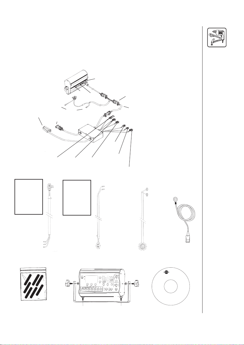
3.0 COMPONENT PARTS AND ASSEMBLY
HARDWARE
Before beginning installation, check the carton contents for the
following items:
Radar
Input
Console
Hitch
Connector
Extension
Cable
Console Cable
System Power Cable
Extension Cable
Sprayer Control Module
Operator's Manual
®
HARDI
Sprayer
20-pin Connector
Foamer
RS-232
Remote
Run/Hold
+
Power
-
With standard
set-up,
included are 23 wire adapter
cables and 1-2
wire adapter
cable
3 wire
Heat Shrink Kit
Pressure
Natural Tie
Speed
Yellow Tie
Flow
Green Tie
With twin force
set-up,
included are 3-
2 wire adapter
cables and 3-3
wire adapter
cables
2 wire
Mounting kit for console
RPM Adjust
Blue Tie
Slot Angle Adjust
Grey Tie
RPM
Red Tie
Optional
Remote
run/hold cable
Optional: Remote
Run/Hold Cable and
Foot Switch
Chassis Ground
Wire
Utilities CD
0XVWDQJ
HARDI
®
MUSTANG 3500 OPERATOR’S MANUAL
6
Page 10
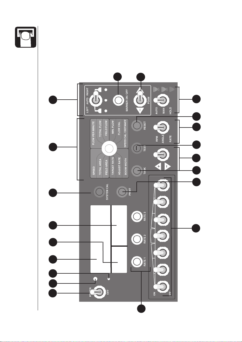
4.0 CONSOLE FUNCTIONS
This section gives a brief explanation of each button, switch and
rotary switch position, and will help to familiarize you with the
console and its operation.
7
6
5
4b
4a
7a
7b
8
91011
12
14 13
15
4
3
2
1
16
7 HARDI®MUSTANG 3500 OPERATOR’S MANUAL
Page 11
1
Main POWER switch
2
Light SENSOR; senses ambient light, turns back lighting on/off
3
WARNING light
4b
4a
4
DISPLAY area; upper half displays application rate; lower left
displays pressure; lower right displays rotary switch position
data
5
SYSTEM CAL button; used to enter system calibration mode
6
ROTARY SWITCH positions:
RATES:
Speed – displays ground speed
Flow Per Minute – displays either total boom or individual nozzle
flow per minute
COUNTERS:
Total Area – keeps a running count of total area
Total Flow – keeps a running count of total flow
Field Area – keeps a running count of field area
Field Flo
w – keeps a running count of field flow
CALIBRATION:
Target Rate – target application rate (GPA/LPH)
Min Flow – minimum gallons (liters) per minute
Adjust Rate – on-the-go adjustments to target rate when
operating in AUTO mode
Flow Cal – flow meter calibration value (PPU)
Boom Width – enter the working width for each of your boom
sections
Speed Ca
FOAM MARKER control:
7
LEFT/AUTO/RIGHT switch – controls which side is currently
7a
MARKER ON/OFF – turns foam marker control system on or off
7b
FOAM ADJUST – increases or decreases the foam rate
MASTER switch; determines in which mode the user is currently
8
operating
9
RESET button – clears the selected counter
l/ Distance – enter Speed Cal value in UPP; will also
display accumulated distance travelled
applying foam
HARDI
®
MUSTANG 3500 OPERATOR’S MANUAL
8
Page 12

10
MODE switch: (twin force only)
RPM – RPM of fan is displayed
ANGLE – displays slot angle settings
RATE – displays application rate
11
TEST button – used to enter test speed mode
12
ADJUST switch – used to adjust various settings or rates
13
TANK button – displays the amount of material remaining in tank
14
PRINT button – allows user to print field counter data
15
BOOM switches – on/off control for each boom section
16
RATE buttons – selects a preset target application rate for each
button.
®
9
HARDI
MUSTANG 3500 OPERATOR’S MANUAL
Page 13

5.0 OPERATION OF THE HARDI®MUSTANG 3500
1
POWER SWITCH
In the ON position, the power switch controls 12-volt power to the entire
system. In the OFF position, there will be no drain to the vehicle’s
electrical system.
Start-up of the HARDI®MUSTANG 3500
Upon start-up, the console will briefly (approximately three seconds)
display the software versions that are programmed into the console
and sprayer control module.
Fig. 5.1
Upper half displays console main program version (flash 1)
Lower left displays Spray Control Module program version (flash 3)
Lower right displays console display program version (flash 2)
®
HARDI
MUSTANG 3500 OPERATOR’S MANUAL
10
Page 14
2
LIGHT SENSOR
This sensor automatically turns the back lighting for the front panel on or
off as the lighting conditions dictate.
3
WARNING LIGHT
The console is equipped with a RED warning light. The light will
automatically turn on and flash when the actual application is plus or
minus 10 percent of the calibrated target rate. The RED warning light will
also be flashing when calibration mode is active on the console.
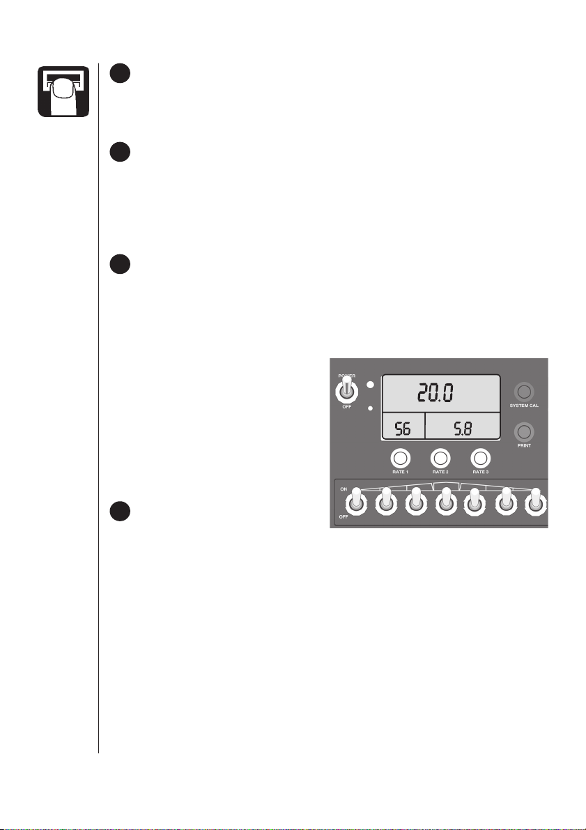
4
DISPLAY AREA
During normal operation, the console will display pressure in the lower
left corner of the display (if installed), application rate in the upper half of
the display and the selected rotary switch position data in the lower right
of the display. For example, in the figure below, the upper display tells the
operator that the actual target
RATE 1 is 20.0 GPA. The lower left
display tells the operator that their
pressure is at 56 PSI, and the
lower right display tells the
PSI
Rate 1
Gal/Acre
Data
operator that their speed is
currently 5.8 MPH, if the rotary
switch is set to speed.
5
SYSTEM CAL BUTTON
To enter system calibration, toggle
the Master switch to HOLD and turn the rotary switch to SPEED, then
press and hold the SYSTEM CAL button and turn the power switch ON.
Release the SYSTEM CAL button when the console displays SYS.
Upon entering SYSTEM CAL, the display will read “SYS” and the
calibration indicator will be lit. Any changes to the factory-preset values
can be made while in SYSTEM CAL. Changes will take effect as soon as
SYSTEM CAL is exited. To exit SYSTEM CAL, press the SYSTEM CAL
button. See Calibration section for more information.
11 HARDI®MUSTANG 3500 OPERATOR’S MANUAL
Page 15

6
ROTARY SWITCH POSITION
During normal operation, you can view any one of six monitored functions
in the lower right portion of the display by turning the rotary dial to the
appropriate position. The GREEN positions are Operational positions
and the RED positions are Calibration positions. The following describes
the function of each Operational position. The Calibration positions are
discussed in Chapter 7: Calibration.
SPEED:
Displays the ground speed in miles (kilometers) per hour.
FLOW PER MINUTE:
Displays the actual gallons (liters) per minute being applied by the
sections turned on. OR if the number of nozzles is entered in System
Cal, then this position will display flow per nozzle in ounces per minute
(liters per minute).
TOTAL AREA:
Displays the area covered since the counter was last reset to zero.
This counter does not accumulate area when the console is in HOLD
or if all boom section switches are turned off. If this counter is reset
TOTAL FLOW will reset as well.
FIELD AREA:
Displays the area covered since the counter was last reset to zero.
This counter does not accumulate area when the console is in HOLD
or if all boom section switches are turned off. If this counter is reset
FIELD FLOW will reset as well.
There are 9 field counters (F1-F9). Only the active counter will reset.
To change active counter, console must be in HOLD and rotary
switch in either FIELD AREA or FIELD FLOW. The lower left display
area will display F1-F9. To change use Adjust switch.
TOTAL FLOW:
Displays the total gallons (liters) applied since the counter pair was last
reset to zero. If this counter is reset TOTAL AREA will reset as well.
®
HARDI
MUSTANG 3500 OPERATOR’S MANUAL
12
Page 16
FIELD FLOW:
Displays the total gallons (liters) applied since the counter was last
reset to zero. If this counter is reset FIELD AREA will reset as well.
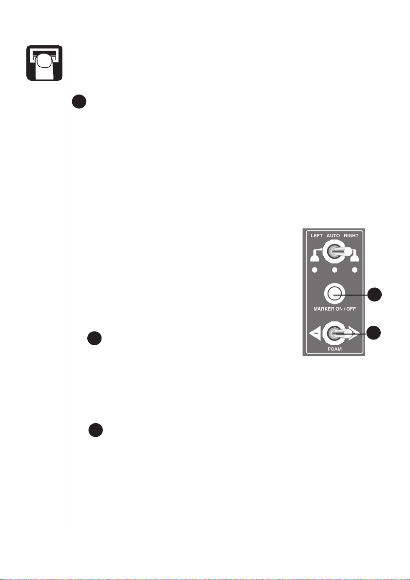
7
FOAM MARKER CONTROL
The area on the far right of the control panel, outlined with a yellow
border, is the Foam Marker Control area. This area is broken down into
three sections, each explained here:
LEFT/AUTO/RIGHT SWITCH:
Moving the switch to the left activates the LEFT foam marker. Moving
the switch to the right activates the RIGHT foam marker. Moving the
switch to the center position tells the controller to automatically
determine which marker will distribute foam. The middle AMBER
colored LED indicates marker is ON. The RED colored LED below the
dropper indicates which side is ON. NOTE: If the
switch is in the center (AUTO) position on
start-up, the marker is set to start distributing
foam on the left side. When in AUTO marker
side changes automatically when the operator
transitions the master switch from AUTO to
HOLD or MAN to HOLD. Foam marker will NOT
turn on if the Master switch is in HOLD or if the
console is in rHold.
7a
MARKER ON/OFF BUTTON:
To activate the Foam Marker in AUTO mode,
press the Marker On/Off button momentarily. To activate the foam
marker in Manual mode, press and hold the Marker On/Off switch
button for three seconds; when in Manual mode, the amber LED will
flash. In Manual mode, the Auto position of the Left/Auto/Right switch
turns the foam OFF.
7a
7b
7b
FOAM ADJUST SWITCH:
When the Foam Marker Control is active, moving the switch to the left
decreases foam rate. Moving the switch to the right increases the foam
rate. When the foam switch is toggled, the lower right area of the
console display shows a percentage value between 0-100% indicating
the foam drop rate: 0%=min. 100%=max.
13 HARDI®MUSTANG 3500 OPERATOR’S MANUAL
Page 17
8
AUTO/MAN/HOLD SWITCH or MASTER SWITCH
This MASTER switch will change the control status of the system from
fully automatic control (“AUTO”), manual control (“MAN”), or HOLD.
During normal operation, when the MASTER switch is in AUTO, the
console adjusts the regulating valve to maintain the desired application
rate. For example, as speed increases, pressure will increase
automatically in order to maintain the desired application rate. As speed
decreases, pressure decreases.
During normal operation, when the MASTER switch is in MAN, the
application rate will not
be maintained by the console automatically.
Using the ADJUST switch while in MAN allows the operator to increase
or decrease the flow or pressure manually as needed.
During normal operation, when the MASTER switch is in HOLD, all
section valves are turned off, (spraying will stop) and area, distance and
flow will stop accumulating and foam marker will stop. For example, when
turning on end rows, place the MASTER switch in HOLD.
9
RESET BUTTON
The RESET button is used to clear a selected counter. To do this, simply
turn the rotary dial to any of the counter positions (Total Area, Field Area,
Total Flow, Field Flow, or Distance), and press and hold the reset button
for one second. IMPORTANT: when clearing field area, field flow is
cleared as well. The same holds true for total area and total flow.
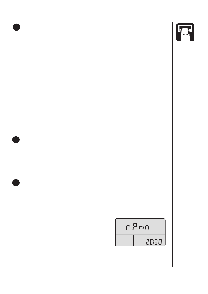
10
MODE SWITCH (TWIN FORCE CONSOLE ONLY)
TWIN FORCE SWITCH:
RPM Position – In this position, fan speed can be adjusted. To do
this, place the switch in the RPM position, and use the “adjust”
switch to increase or decrease the fan speed. The console will not
allow fan speed greater than 3200
RPM.The console will show “fan RPM”
in the lower right while in this mode, and
RPM will be displayed in the upper half
of display indicating the mode the user
is in. If the PTO is disengaged and
hydraulic flow to the Fan motor stops, causing Fan RPM to read 0,
the system will automatically take the hydraulic pump output to the
lowest setting.
HARDI®MUSTANG 3500 OPERATOR’S MANUAL
14
Page 18
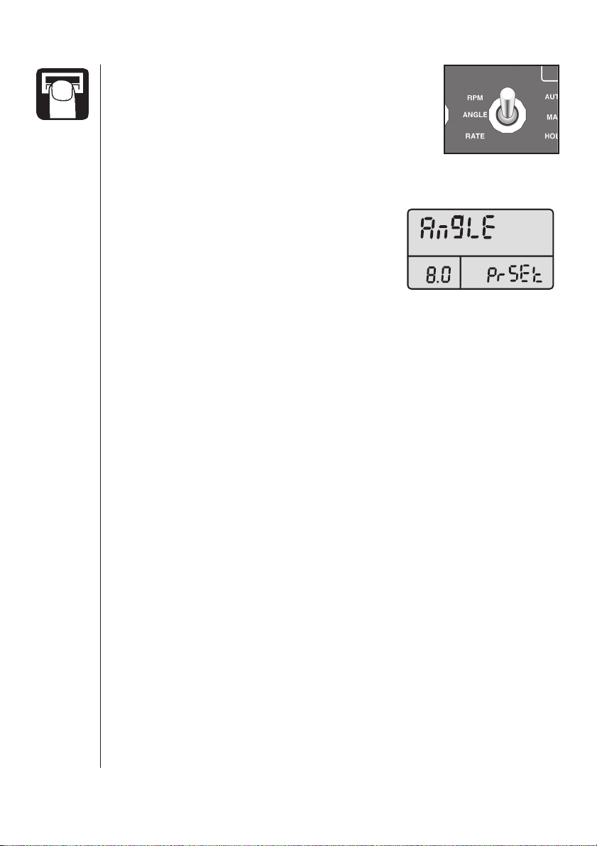
ANGLE Position – This position is used to
adjust the slot angle. To do this, place the
switch in the ANGLE position, and use the
“adjust” switch to increase or decrease the
slot angle.
There are 3 modes of operation for the Slot Angle feature on the HARDI
Mustang 3500: Manual, Preset and Auto.
WHEN ENTERING THE SLOT ANGLE
MODE: if the user places the Mode Switch in
Rate
2
1
N / Ac
ERROR
inches
liters / ha
the Angle position, the top half of the LCD
reads AnglE and either RATE 1, 2, or 3. The
lower left reads a number between .0 and
meters
12.0 and the lower right display reads either Auto or PrSEt (preset).
MANUAL MODE: To operate the Slot Angle manually, simply place the
Mode Switch in ANGLE and the Rotary Switch in any green (operational)
position, using the Adjust Switch, manually change the Slot Angle to the
desired position.
PRESET MODE: To operate the Slot Angle in the Preset Mode, toggle
the MODE SWITCH to the ANGLE position and the ROTARY SWITCH
to any green position (the lower right area of the display must read
PrSET).
If the RATE 1, 2 or 3 button is pressed, the Slot Angle will transition
•
to the associated preset value. The value in lower left display represents
the time in seconds the Slot Angle actuators will run from the zero point.
If the value in RATE 1 is set to 2.5 and the Rate 1 button is pressed, the
Slot Angle will run forward for 12 seconds and then rearward for 2.5
seconds.
If the value in Rate 2 is set to 4.7 and the RATE 2 button is pressed,
•
the Slot angle will run forward for 12 seconds and then rearward for 4.7
seconds.
®
15
If the value in Rate 3 is set to 6.2 and the RATE 3 button is pressed,
•
the Slot Angle will run forward for 12 seconds and then rearward for 6.2
seconds. To adjust the preset value the Mode Switch must be in the
ANGLE position, the Master Switch in HOLD and the Rotary Switch in
any calibration (red) position, to adjust, select the associated RATE
button and adjust the value using the Adjust Switch.
®
HARDI
MUSTANG 3500 OPERATOR’S MANUAL
Page 19

AUTO MODE: To toggle the Angle Mode between AUTO and PRESET,
toggle the mode switch to ANGLE and the MASTER switch to
the ROTARY switch to any calibration position. By then pressing the RESET
button, the Angle mode will toggle between PRESET and AUTO, In the AUTO
mode, the Slot Angle will automatically change from the RATE 1 preset
position to the RATE 3 preset position on a MASTER SWITCH transition from
AUTO to HOLD or on a REMOTE HOLD (foot switch) transition. To adjust the
preset values in the lower left display area place the mode switch in ANGLE
and the MASTER switch in HOLD and the ROTARY switch in any calibration
position, then press the associated RATE button and adjust the value using
the ADJUST switch. In the AUTO mode, the Slot Angle will run to the zero
point (12 seconds forward) and then to the PRESET value every other time
the MASTER switch is toggled from AUTO to HOLD.
HOLD and
SAFETY FEATURE: To immediately stop Slot Angle movement in either
AUTO or PRESET mode turn the ROTARY SWITCH to any calibration
position.
11
TEST BUTTON
The TEST button is used to enter the Test Speed mode when calibrating
the system. Refer to Pre-field System Checkout for more information on
Test Speed and using the TEST button.
12
ADJUST SWITCH
The “+/–” (ADJUST) switch serves many functions within the system, and
can be used within Calibration and Operation (AUTO and MAN).
During normal operation, when the master switch is in automatic (AUTO)
and the rotary dial is not in a calibration position, each toggle of the switch
will increase or decrease the target application rate by the amount of the
calibrated ADJUST RATE.
During normal operation, when the master switch is in manual (MAN),
toggling the ADJUST switch will increase or decrease the application rate
by closing or opening the regulating valve (control valve).
TANK BUTTON
13
This button is used to check the volume remaining in the tank. To do this,
turn the rotary dial to any of the six operational positions (top half), and
press and hold the TANK button. The top half of the display will show the
volume remaining in the tank. When the TANK button is released, the
display will revert back to the application rate.
The TANK button can also be used to enter a volume into the tank counter.
To do this, press and hold the TANK button and toggle the “ADJUST” switch
HARDI®MUSTANG 3500 OPERATOR’S MANUAL
16
Page 20
up to the “+” position. This sets the tank counter at its maximum
(determined by tank size in System Calibration, see Chapter 8:
Calibration).
To enter a volume other than maximum, press and hold the TANK button
and toggle the “ADJUST” switch up (“+”) first to set the maximum, then
down (“–”). This will cause the counter to count down slowly. (Toggling to
“+” will again set the counter at its maximum.)
NOTE: A tank volume can be entered even if tank size is “OFF” in
System Calibration, but it will increase slowly with the “+” switch
rather than instantly going to maximum.
14
PRINT BUTTON
This button is used to print a data list using a HARDI®printer. To do this,
place the console in HOLD, and press the PRINT button.
15
BOOM SECTION SWITCHES
The boom switches on the console are designed to start and stop the flow
of material through each individual boom section switch you have
programmed. The console accumulates area based on the calibrated
boom section widths. When an individual boom section is turned off, the
respective width is subtracted from the total width to accumulate area
based on the new active application width. If a boom section switch is
turned on, its respective section valve should be on. If a boom section
switch is turned off, its respective section valve should be off. No valves
should be on if the console is in HOLD, or in AUTO while speed is zero.
16
RATE BUTTONS
17
The RATE buttons serve many functions within the system, and can be
used within Calibration and Operation (AUTO and MAN). The RATE
buttons allow you to quickly select an alternative pre-programmed rate.
They can be used in several different ways.
While in operation, the RATE buttons are used to select which preprogrammed rate you will use during application. For example, RATE 1
could be set at a low-end rate (e.g. 8 GPA), RATE 2 at a mid-range rate
(TARGET, e.g. 10 GPA), and RATE 3 a high-end rate (e.g.12 GPA).
Another example might be this: If you are using triple nozzle bodies with
different nozzle installations, you could pre-program the HARDI
MUSTANG 3500 for each specific nozzle. This will save time when
changing nozzles for each specific application.
The Rate buttons are also used in calibration. See Chapter 8;
Calibration.
®
HARDI
MUSTANG 3500 OPERATOR’S MANUAL
®
Page 21

System Overview of the HARDI®MUSTANG 3500
(NOT for Twin Force)
Foamer
®
HARDI
20-pin Connector
Sprayer
Radar
Input
RS-232
+
Power
Remote
Run/Hold
-
Pressure
Natural Tie
Console
Cable
System
Power
Cable
Hitch
Connector
Extension
Cable
HARDI
Speed
Yellow Tie
®
MUSTANG 3500 OPERATOR’S MANUAL
Flow
Green Tie
18
Page 22

System Overview of the HARDI®MUSTANG 3500
(for Twin Force operation)
Foamer
®
HARDI
20-pin Connector
Sprayer
Pressure
Natural Tie
Radar
Input
RS-232
+
Power
Speed
Yellow Tie
Remote
Run/Hold
-
Flow
Green Tie
Slot Angle Adjust
Console
Cable
RPM Adjust
Blue Tie
Grey Tie
System
Power
Cable
Hitch
Connector
Extension
Cable
RPM
Red Tie
19 HARDI®MUSTANG 3500 OPERATOR’S MANUAL
Page 23

6.0 INSTALLATION
Mounting the Display Console
Select a mounting location which seems most workable, and that best
fits your needs. It should be convenient to reach and highly visible to
the operator. DO NOT INSTALL IN A POSITION THAT OBSTRUCTS
THE VIEW OF THE ROAD OR WORK AREA.
Place the mounting bracket in the selected location, mark holes,
drill 1/4" (7mm) holes and mount bracket with bolts, lockwashers and
nuts provided. (If bolts are not practical, use self-tapping screws.) See
Figure 7.1.
Fig. 7.1
A chassis ground wire is provided to reduce electrical interference.
This wire is connected to the male terminal on the back of the console
and then to a good chassis ground point.
Place the console in the “U” bracket and install the console knobs
through the bracket, placing a rubber washer over the threaded stud.
Position console to proper viewing angle and tighten the knobs
securely. See Figure 7.1.
20HARDI®MUSTANG 3500 OPERATOR’S MANUAL
Page 24

Electrical Installation
The HARDI®MUSTANG 3500 must be connected to a 12-volt DC
electrical system. Power is connected directly to the battery, or other
30 AMP power outlet. The HARDI
switch on the console to turn the power off when the system is not
being used.
Locate the system power cable. Connect the blue ground wire to a
good frame ground, be sure there is good metal-to-metal contact. See
Figure 7.3. Route the power cable from the battery to the back of the
tow vehicle. In routing cable to battery, avoid areas where the cable
may be subjected to abrasion or excessive heat. Connect the
ORANGE wire (hot) to the positive battery terminal.
®
MUSTANG 3500 has an ON/OFF
Your HARDI
®
MUSTANG 3500 is equipped with an electronic memory which does not require a constant supply of power to retain daily
totals or calibration values. The advantage with this type of memory
is that it conserves battery power and will not discharge the vehicle’s
battery when the power switch is off.
30-amp in-line
Hot +
(ORANGE)
fuse required.
+
Ground
NOTE: For
negative ground
systems only.
-
Ground
-
(BLUE)
Fig. 7.3
21
HARDI®MUSTANG 3500 OPERATOR’S MANUAL
Page 25

Speed, Flow and RPM Transducer Installation
The HARDI®Mustang will work with either the magnetic speed
transducer or proximity speed transducer. DO NOT USE MAGNETS
WITH THE PROXIMITY TRANSDUCER. Wiring remains the same for
either speed transducer. For magnetic transducers, the sensor needs
to be placed 5-7 mm from the magnet. For proximity transducers, the
sensor needs to be placed 1.5-3 mm from the magnet mount bracket
(NO MAGNETS USED).
®
Route the speed sensor cable to the HARDI
Mate the wires as shown below. Be sure to slide a piece of heat shrink
tubing over each individual wire before mating. Then shrink tubing by
applying heat evenly along tube. Plug the adapter cable into Sprayer
Control Module speed input pigtail with Yellow Cable Tie. DUPLICATE
THIS FOR FLOW, AND RPM SENSOR INTERFACE.
Sprayer Control Module.
Speed, Flow
or RPM
Sensor
Blue
Brown
Black
Red
White
Black
3 wire adapter cable
For old infield sprayers, a magnet mount bracket may be required:
10587803 – Magnet Mount Bracket 8-bolt
16020203 – Magnet Mount Bracket 10-bolt
Note: the magnet mount brackets are used with both types of speed
transducers even though magnets are not used with the proximity
speed transducer.
16020203
10587803
Proximity speed transducer
HARDI
®
MUSTANG 3500 OPERATOR’S MANUAL
22
Page 26

3 WIRE ADAPTER CABLE WIRE COLOR CODE
Wire color Connection for transducer
WHITE 12V supply
BLACK Ground
3/16-1/4"
(5-7 mm)
RED Signal
SPEED, HALL- EFFECT, AND PROXIMITY
N
SENSOR CABLE WIRE COLOR CODE
ire color Connection for transducer
W
BROWN 12V supply
BLACK Ground
BLUE Signal
RPM SENSOR CABLE WIRE COLOR CODE
ire color Connection for transducer
W
BROWN 12V supply
BLACK Ground
BLUE Signal
FLOW TRANSDUCER CABLE WIRE COLOR CODE
ire color Connection for transducer
W
BROWN 12V supply
BLACK Ground
BLUE Signal
S
23
Note: Route the cables from the module to
the sensor location hiding all excessive
cable under the sprayer frame.
®
HARDI
MUSTANG 3500 OPERATOR’S MANUAL
N
S
S
N
Page 27

Installing Pressure Transducer
The optional pressure transducer is installed in one of the section feed
hoses. A 3/4" tee (#322048) is installed in a convenient place in the
hose (between the control and the boom). In a 3-feed boom, install the
pressure transducer on the center hose. In a 4-feed or higher boom,
install the pressure transducer on one of the center hoses (whichever
is closest to the control). Thread the pressure transducer onto the tee.
Route the cables back to the HARDI
the two wires into the appropriate terminals.
ADAPTER CABLE COLOR CODE
W
ire color DESCRIPTION
RED +12V supply
BLACK Signal
PRESSURE TRANSDUCER COLOR CODE
W
ire color DESCRIPTION
BROWN +12V supply
BLUE Signal
Route the Pressure Transducer Cable to the HARDI
Module. Mate the wires as shown below. Be sure to slide a piece of
heat shrink tubing over each wire before mating. Then shrink tubing
by applying heat evenly along tube. Plug adapter cable into Sprayer
Control Module pressure input, pigtail with Natural colored tie.
®
Sprayer Control Module and plug
®
Sprayer Control
Pressure Sensor
Blue
Brown
HARDI
Black
Red
®
MUSTANG 3500 OPERATOR’S MANUAL
2 wire adapter cable
24
Page 28

Installation: Twin force
RPM and Slot Angle Adjust
First locate the electric over hydraulic control box at the back of the
sprayer and remove cover. Locate the two cables coming from adjacent
box connecting to V7 (slot angle) and V8 (RPM adjust), see picture
below.
25
Electric over hydraulic junction box for twin force located on inside of twin
force center section.
Route the two supplied 2-wire 25 foot adapter cables from the Sprayer
Control Module to the electric over hydraulic control box. Be sure to
mark the cables at the fling lead end with colored ties provided. Blue tie
for RPM and gray tie for slot angle. At the electric over hydraulic control
box, insert both adapter cables into hydraulic control box through
separate spare rubber gromets at the bottom of hydraulic control box. Be
sure to strain relief similar to other incoming cables. Pull the brown and
blue wires at V7 from the board (slot angle adjust) and mate them with
the slot angle adjust wires, red to blue and black to brown. Be sure to
slide a piece of heat shrink over wires before mating.
®
HARDI
MT-9000 OPERATOR’S MANUAL
Page 29

Electric over hydraulic junction box for twin force located on inside of twin
force center section.
Follow this procedure again for the RPM adjust at V8. Test for correct
operation of slot angle adjust and RPM adjust before sealing heat
shrink. Shrink tubing by applying heat evenly along length of tubing.
Replace cover on hydraulic box.
HARDI
®
MT-9000 OPERATOR’S MANUAL
26
Page 30

7.0 CALIBRATION
In this chapter, we will help you calibrate your system specifically for
your liquid application needs. Follow these procedures carefully to make
sure you are properly prepared before you get to the field.
A Software Utility package is provided with each system. If you have
access to a PC with CD drive, this software can be easily loaded onto a
PC or Pocket PC. The Utility Software includes a calibration “wizard”
that directs the operator through the MUSTANG calibration process and
automatically sets up calibration for various types of systems. If the PC
is connected to the MUSTANG, the calibration parameters can be
downloaded directly to the MUSTANG, or the calibration settings can be
printed out and entered into the MUSTANG manually. The Utility
Software also provides the ability to reprogram the MUSTANG with
program upgrade files provided by HARDI
See the Compact Disc you received with your MUSTANG Automatic
Rate Controller.
®
via e-mail (or on floppy disk).
27
A 9-pin RS-232 cable is used to connect the HARDI
®
MUSTANG 3500
to a PC, not Null Modem. The HARDI®MUSTANG 3500 must also be
connected to a 12-volt DC power source in order to communicate with
the PC.
We’ll begin with the System Calibration section.
®
HARDI
MUSTANG 3500 OPERATOR’S MANUAL
Page 31

Entering SYSTEM Calibration Values
CAL
The HARDI®MUSTANG 3500 has a number of control functions which
are preset at the factory (See Factory Calibration Chart on page 51). In
some cases, however, it may be necessary to change one or more of
these settings to enhance performance or meet special operational
requirements. To make these changes, you need to enter System
Calibration. To enter System Calibration:
1. Turn the power switch OFF.
2. Place the AUTO/MAN/HOLD switch in the HOLD position.
3. Place the Rotary switch in the SPEED position.
4. While pressing the SYSTEM CAL button, turn the power switch ON.
NOTE: The console will display “SYS” (SYSTEM) and “Cal” in the
upper display window. The warning light will flash. See Figure 8.1.
Exiting System Calibration
5. When all necessary changes have been made, exit SYSTEM CAL.
To do this, press the SYSTEM CAL button. All changes are
immediately saved to memory.
Fig. 8.1
HARDI
®
MUSTANG 3500 OPERATOR’S MANUAL
28
Page 32

Units (Default setting = 'Eng')
PSICAL bar datameters inches
Rate
ERROR
123
Gal / Ac
kg / ha
Lbs N / Ac
liters / ha
Gal / 1000
datameters inches
This “System Cal” position is used to select the units of measure for the
system. The units of measure determine how data is displayed and
how volume, distance and area calculations are made. Use the
ADJUST switch to select the desired units of measure for the system.
Dial position: Display will read:
TARGET RATE
EnG = American English
mEt = Standard metric
Flow Per Minute may optional show ounces/min (See "Tips"
section of System CAL on page 31.
29
UNITS OF MEASURE CHART
ENGLISH METRIC
AREA Acres Hectares
VOLUME Gallons Liters
SPEED Miles/Hr. Kilometers/Hr.
DISTANCE Feet Meters
PRESSURE Pounds/Sq. In. Bar
FLOW PER MINUTE Gallons/Min. Liters/Min.
SPRAY RATE Gallons/Acre Liters/Hectare
®
HARDI
MUSTANG 3500 OPERATOR’S MANUAL
Page 33

Sections (Default setting = factory preset)
PSICAL bar meters
inches
Rate 12 3
N
/ Ac
Gal / 1000
3
PSICAL bar
Rate
12 3
3
The SYSTEM CAL position is used to set the number of sections the
sprayer has. This number can be set to 3-7. This number is set at the
factory, the operator should not need to adjust this setting.
Dial position: Display will read:
ADJUST RATE
Dial position: Display will read:
Tips (Default setting = '0)
This SYSTEM CAL position is used to determine which type of Flow
rate is displayed in the Flow Per Minute rotary position:
A) Flow for the entire boom - Flow Per Boom
When TIPS = 0
Gallons per minute (Liters per minute) is displayed for the entire boom
B) Flow for individual sprayer tip - Flow Per Nozzle
When set to a nonzero
boom size MAX ounces 6553.5 per minute
NOTE: It is very important to ensure that the total number of spray tips
is entered or else the Flow Per Nozzle
calculated.
value (TIPS = typically 24-73) depending on
rate will be incorrectly
BOOM WIDTH
Dial position: Display will read:
HARDI
®
MUSTANG 3500 OPERATOR’S MANUAL
30
Page 34

PSICAL bar meters
inches
Rate
ERROR
123
N / Ac
liters / ha
Gal / 1000
3
FLOW CAL
PSICAL bar meters
Rate123
N
/ Ac
3
Regulation Polarity (Default setting = POS)
data
meters
inches
This SYSTEM CAL position can be used, if necessary, to change the
polarity of the pressure regulation valve. The default setting (POS)
should correct for most installations.
Dial position: Display will read:
SPEED CAL/DISTANCE
Regulation Constant (Default setting = 2)
This SYSTEM CAL position is used to make adjustment to how
aggressive the regulation valve is allowed to operate when in AUTO
mode. The default setting (2) should be correct for most installations.
31
A setting of "1" is the most aggressive, "8" is the least aggressive. If
regulation valve tends to overshoot the target, increase this number. If
more performance is required (response speed), decrease this valve
Dial position: Display will read:
HARDI MT-9000 OPERATOR’S MANUAL
Page 35

PSICAL bar datameters inches
Rate
ERROR
123
Gal / Ac
kg / ha
Lbs N / Ac
liters / ha
Gal / 1000
Sprayer Type (Default setting = Evc)
PSICAL bar meters
inches
Rate
ERROR
123
N
/ Ac
liters / ha
G
3
This SYSTEM CAL position is used to select the sprayer type, which
controls the behavior of the section valves based on whether or not the
system contains a MAIN vavle.
"EC": If the sprayer system has a MAIN on/off valve select
"EC". With this setting, when console is put into HOLD, only the MAIN
valve will shut off, the individual section valves are left alone.
"EVC": If MAIN valve is not present, select the "EVC". With this
setting, when the console is put into HOLD, all section valves will be
turned off.
Dial position: Display will read:
MIN. FLOW
Tank Alarm Set Point (Default setting = OFF)
This SYSTEM CAL position is used to SET the audible alarm to alert
the operator when the tank has reached this preset level. SET this
value to the desired level in gallons (liters). NOTE: When the alarm
activates, press the TANK button to shut off.
Dial position: Display will read:
FIELD FLOW
HARDI
®
MUSTANG 3500 OPERATOR’S MANUAL
32
Page 36

Tank Size: (Default setting = OFF)
PSICAL bar meters
123
3
PSICAL bar datameters inches
Rate
ERROR
123
Gal / Ac
kg / ha
Lbs N / Ac
liters / ha
Gal / 1000
This SYSTEM CAL position is used to set the value for the volume size
of the main product tank. Adjust the value to match the volume size in
gallons (liters).
Dial position: Display will read:
TOTAL FLOW
Filter: (Default setting = 1)
This SYSTEM CAL position adjusts the amount of filtering used to
display the Application Rate value shown in the UPPER display window
(gallons/acre) and Flow Per Nozzle value shown in lower right
(ounces/minutes).
• Flow Per Nozzle is only displayed when "TIPS" is a nonzero number.
If TIPS is set to 0. then the Flow Per Boom = gallons/minute
(liters/minute)
The filtering only affects the amount of averaging and response time
applied to the displayed values. All calculations and control elements
of the electronic console uses the "raw" or the instantaneous values.
If filter is set to OFF, then all of the displayed values are shown "raw" or
instantaneous. This can be used to help diagnose/troubleshoot system
problems which could be causing flowmeter instability.
33
Dial position: Display will read:
FLOW PER MINUTE
®
HARDI
MUSTANG 3500 OPERATOR’S MANUAL
Page 37

Exiting System Calibration
Upon completion of the special calibration process, exit special
calibration by simply pressing the SYSTEM CAL button. Proceed with
Standard Liquid Calibration before beginning operation.
Before beginning operation, refer to Test Speed and Pre-field System
Checkout on pages 37 and 38. This will confirm your calibration
settings, nozzle selection and overall system performance.
Entering STANDARD Calibration Values
Once in calibration mode, you may change any one, all or none of the
values, in any order. To enter calibration mode, simply turn the rotary
selector to the desired calibration position. Use the ADJUST switch to
adjust values. Calibration positions are identified as RED with white
type (lower six positions).
Entering Standard Calibration
To enter calibration, proceed as follows:
1. Place the AUTO/MAN/HOLD switch in HOLD.
2. Turn the rotary dial to any of the six (RED) calibration positions.
The console will display CAL and the warning light will flash. See
Figure 8.2.
CAL
Fig. 8.2
HARDI MT-9000 OPERATOR’S MANUAL
34
Page 38

Target Rate
PSICAL bar datameters inches
RateERROR 1 2 3
Gal / Ac
kg / ha
Lbs N / Ac
liters / ha
Gal / 1000
PSICAL bar datameters inches
Rate
ERROR
1 23
Gal / Ac
kg / ha
Lbs N / Ac
liters / ha
Gal / 1000
This position is used to enter the value for the desired target application
rate in GPA or LPH. Up to three rates can be programmed from 0.1 to
6553.5. Press RATE 1 to enter your first rate, RATE 2 to enter your
second rate, and RATE 3 to enter your third target rate. Use the
ADJUST switch to adjust the value displayed to the desired rate.
Dial position: Display will read:
TARGET RATE
Note: If you will not be using the adjust rate feature, set the value
to zero (0). This will help to prevent any accidental target rate
changes.
Adjust Rate
Enter the value for the desired amount of change in GPH/LPH to be
used for making on-the-go rate adjustments when operating in AUTO.
You may set an adjust rate value for each target rate. Press RATE 1 to
enter the adjust rate for Rate 1, press RATE 2 to enter the adjust rate for
Rate 2, and press RATE 3 to enter the adjust rate for Rate 3. Use the
ADJUST switch to adjust the value displayed to the desired rate.
ADJUST RATE
35
HARDI
®
MUSTANG 3500 OPERATOR’S MANUAL
Page 39

Speed Cal/Distance
PSICAL bar datameters inches
Rate
ERROR
123
Gal / Ac
kg / ha
Lbs N / Ac
liters / ha
Gal / 1000
This position is used to calibrate the speed transducer for accurate
speed, distance and area measurement. When this position is
selected, the display will show the Distance Cal value and the distance
travelled. Either one may be used to calibrate for speed and distance
measurement. (If using radar, enter factory calibration number.)
Dial position: Display will read:
Distance
travelled
SPEED CAL/DISTANCE
Distance
CAL factor
(UPP)
Determining Distance/Cal Factor (UPP)
For the console to calculate the correct speed and measure distance
and area accurately, the circumference of the sensor-equipped wheel
must be determined. Determine the circumference of the sensormounted wheel, to the nearest tenth of an inch (thousandth of a meter),
with the following method:
Mark the tire with a piece of chalk and measure the distance travelled on
the ground for one complete revolution. See Figure 8.3. For improved
accuracy, it is recommended to perform this function in field conditions,
(with tank half-full), measure several revolutions, and take the average.
Divide the measured revolution by the number of magnets installed.
HARDI
®
MUSTANG 3500 OPERATOR’S MANUAL
36
Page 40

Divide the measured revolution by the number of magnets installed. Divide
PSICAL bar datadata inches
RateERROR 12
Gal / Ac
kg / ha
Gal
N / Ac
liters / ha
Gal / 1000
the result by two to get your starting UPP value. Once calibration of the
system is complete,this number should be fine-tuned for optimum accuracy.
Please refer to Fine-Tuning Speed/Distance Calibration Value on page 54.
Fig. 8.3
To determine circumference, measure the distance of one complete wheel revolution and
divide by the number of magnets installed. Divide the result by two.
Flow Cal
This position is used to enter the flow cal number. It represents the number
of pulses per gallon (PPU) for that particular flowmeter. The same value is
used for both English and Metric. Use the ADJUST switch to enter this
value. For pressure-based control (no flow meter installed), enter zero
(0.0) as the flow meter calibration value. Please refer to Fine-Tuning Flow
Transducer Calibration Value on page 56.
Dial position: Display will read:
FLOW CAL
Theoretical Flow Meter Calibration (PPU)
Control
EC
EC
EC S67
EC S67
EC S67
ESC
ESC
EVC
THESE ARE STARTING POINTS ONLY. FLOW MUST BE CALIBRATED!
37 HARDI®MUSTANG 3500 OPERATOR’S MANUAL
Flow
2-30 GPM
4-70 GPM
2-30 GPM
4-70 GPM
4-160 GPM
2-30 GPM
4-70 GPM
2-30 GPM
Part #
842020
842088
842081
842082
842228
842021
842098
842191
Code
White
Black
1 groove
no groove
2 groove
1 groove
2 groove
1 groove
Orfice
13.5 mm
20.0 mm
13.5 mm
20.0 mm
36.0 mm
13.5 mm
20.0 mm
13.5 mm
PPU
890.0
450.0
970.0
450.0
950.0
800.0
450.0
910.0
Page 41

Boom Width
PSICAL bar datameters inches
Rate
ERROR
123
Gal / Ac
kg / ha
Lbs N / Ac
liters / ha
Gal / 1000
Enter the working width, in inches (meters), for the boom section
currently shown on the display. Use the ADJUST switch to adjust the
displayed value to the correct width for the boom number (in the top
display). Turn all booms off, display will read SELEC. Begin with the
farthest right boom switch and work your way left, repeating this
procedure for each boom section. A
value of “0” (.000) must be
entered for any unused boom section.
Dial position: Display will read:
BOOM WIDTH
Setting Individual Boom Width
In order to accurately measure the number of units applied per acre, it
is important to determine the correct “working” width. The working width
is the width of ground being affected by any operation. This should be
measured to the nearest inch
(thousandth of a meter).
Your working width will be the number of nozzles on that boom
section times the nozzle spacing in inches (mm). For example, if
you have 7 nozzles spaced at 20 inches, the working width is 140
inches.
ADDITIONAL BOOM WIDTH FEATURE:
To adjust the constant pressure distribution valves, first toggle the
master switch to MAN and the rotary switch to Non-Cal position and
using the adjust switch, adjust the pressure regulating valve to your
target application pressure. After reaching target pressure, rotate rotary
switch to boom width position. After 5 seconds the output to each
distribution valve will be electronically isolated allowing the distribution
valve to be operated manually to adjust bypass to maintain constant
pressure when distribution valve is turned off.
38HARDI®MUSTANG 3500 OPERATOR’S MANUAL
Page 42

Dial position: Display will read:
Gal / 1000
Lbs N / Ac
Gal / Ac
kg / ha
liters / ha
MIN. FLOW
RateERROR 1 23
CAL bar datameters inches
Minimum Flow
The purpose of this calibration parameter is to set the minimum
recommended flow rate for the spray boom and nozzles. Once set, the
system will prevent the actual flow rate from going below the
recommended minimum rating. You may set a minimum flow rate for
each target rate.
Calculating minimum flow value:
Determine from your tip chart what your nozzle’s minimum
minute (liters per minute) rating is at their minimum recommended
pressure. Do not use the gallon per minute of your actual application
rate. For example, if the minimum flow rate per nozzle is .22 GPM at
their minimum pressure and your spray boom has 20 nozzles (all
sections), the minimum flow value is 4.4 (.22 x 20 = 4.4). The system
will not apply at a rate lower than this value when spraying in AUTO.
gallon per
39
Entering minimum flow values:
Each target rate may have a different setting for minimum flow. Press
the RATE 1 button. The lower right portion of the display will show the
minimum flow value. Use the ADJUST switch to adjust the displayed
value to the calculated minimum flow rate value for the nozzles used for
Rate 1.
Repeat the procedure for RATE 2 and 3. If the same nozzles are being
used for Rate 2 and Rate 3, enter the same minimum flow value for
those target rates. If different nozzles are being used, refer to nozzle
manufacturer’s Tip Chart.
®
HARDI
MUSTANG 3500 OPERATOR’S MANUAL
Page 43

Repeat the procedure for RATE 2 and 3. If the same nozzles are being
used for Rate 2 and Rate 3, enter the same minimum flow value for those
target rates. If different nozzles are being used, refer to nozzle
manufacturer’s Tip Chart.
APPLICATION NOTE: In certain situations when spraying in AUTO,
your ground speed may be slow enough to result in an overapplication error. In other words, based on ground speed, the actual
flow rate for your application is below the calibrated minimum.
Remember, in AUTO, the system will not allow the flow rate to drop
below the calibrated minimum.
Control Type:
The following chart shows which values must be entered for each of
the three control types offered in the HARDI®Mustang 3500.
Control Type
Flow
Pressure
Hybrid
Hybrid is defined as pressure based control with flow verify.
Flow Cal
Y
N
Y
Min Flow
Optional
Y
Y
Min Pressure
N
Y
Y
Pressure Sensor Zeroing
If your system is using an electronic pressure transducer, you must zero
the pressure sensor. This procedure sets the zero point of the transducer.
Until the pressure sensor is zeroed, the pressure display
will be blank.
PROCEDURE:
1. Make sure the pressure transducer is installed with
ZERO pressure (no pressure) present.
2. Place the AUTO/MAN/HOLD switchin HOLD.
3. Press and hold the SYSTEM CALbutton while toggling the ADJUST
switch to "
NOTE: The pressure must be re-zeroed if a new transducer is
installed. The pressure transducer can be turned OFF by loading
factory defaults. See “Loading Factory Defaults”, page 43.
–".
HARDI
®
MUSTANG 3500 OPERATOR’S MANUAL
40
Page 44

Standard Factory-Loaded Calibration Values
Standard Cal Purpose Default Values
English Metric
Target RATE 1 20.0 gallons/acre 200.0 liters/hectare
Target RATE 2 20.0 gallons/acre 200.0 liters/hectare
Target RATE 3 20.0 gallons/acre 200.0 liters/hectare
Adjust RATE 1 1.0 gallons/acre 2.0 liters/hectare
Adjust RATE 2 1.0 gallons/acre 2.0 liters/hectare
Adjust RATE 3 1.0 gallons/acre 2.0 liters/hectare
Boom 1 Width 120 inches 3.048 meters
Boom 2 Width 120 inches 3.048 meters
Boom 3 Width 120 inches 3.048 meters
Boom 4 Width 120 inches 3.048 meters
Boom 5 Width 120 inches 3.048 meters
Boom 6 Width 120 inches 3.048 meters
Boom 7 Width 120 inches 3.048 meters
Distance UPP Speed, distance, area, rate 1.75 inches/edge 0.044 meters/edge
Flowmeter PPU App. rate, flow rate 155.0 155.0
Min Flow 1 0.0 gallons/minute 0.0 liters/minute
Min Flow 2 0.0 gallons/minute 0.0 liters/minute
Min Flow 3 0.0 gallons/minute 0.0 liters/minute
Application rate
Amount of increase or
decrease per +/– press
(During AUTO control)
Area and application rate
Lowest allowable flow
rate in AUTO
41
System Cal
Units
Section
Tips
Regulation
Polarity
Regulation
Constant
Type
Tank Set Point
Tank Size
Filter
Purpose
Select units of measure
Number of sections sprayer has
Type of flow rate
Change polarity of pressure
regulation valve
Adjust aggressiveness of
regulation valve
Select sprayer type
Set alarm
Set value of volume size
of main tank
Adjusts amount of
filtering used in displays
®
HARDI
MUSTANG 3500 OPERATOR’S MANUAL
English Metric
Eng
33
0
Pos
2
Evc
Off
Off
1
Met
0
Pos
2
Evc
Off
Off
1
Page 45

Loading Factory Defaults
To load factory defaults, do the following:
1. Turn the rotary switch to the SPEED position.
2. Put the AUTO/MAN/HOLD switch in HOLD.
3. Hold the appropriate RATE key and the “+” switch during power-up.
RATE 1 = English
RATE 2 = Metric
NOTE: Loading factory defaults also clears total counter pair and
F1field counter pair, and blanks the pressure display.
Exiting Standard Calibration
Upon completion of the calibration process, exit calibration by simply
turning the rotary dial to any function other than the calibration functions
(RED boxes with white type).
Before beginning operation, refer to Test Speed and Pre-field System
Checkout on pages 43 and 44. This will confirm your calibration
settings, nozzle selection and overall system performance.
About Test Speed
Test speed is a built-in ground speed simulator that is used in
performing pre-field checks. When a typical operating speed is entered,
the HARDI®MUSTANG 3500 will respond as if you were actually driving
that speed. It allows you to simulate your spraying application with plain
water, while remaining stationary, so that you can make certain that all
of the equipment is operating properly and that your sprayer can
actually perform the intended application. Test Speed will not
accumulate distance or area.
42HARDI®MUSTANG 3500 OPERATOR’S MANUAL
Page 46

Pre-field System Checkout
Before beginning actual spraying, perform the following “pre-field”
procedure to ensure that your valve settings, nozzle selection and
desired speed range will allow the HARDI
the required application control. This procedure should be repeated for
each new nozzle selection and/or application rate. By performing all of
the steps listed below, you are setting up your system to allow the
HARDI
®
MUSTANG 3500 to perform at optimum levels.
NOTE: Most nozzles will maintain a good pattern over a maximum
speed range of two to one. (For example, if your maximum speed is 12,
your minimum speed shouldn’t go below 6.)
Make sure you fill your sprayer tank with clean water. DO NOT use
chemicals until the entire system is completely checked out and
operating properly.
The MASTER switch reference in this procedure is the lower right
switch labeled AUTO/MAN/HOLD.
1. Start vehicle and bring pump up to normal operating RPM. Make
sure pressure does not exceed safe operating limits for your
system.
®
MUSTANG 3500 to provide
43
2. Put the master switch in HOLD. Turn rotary switch to the SPEED
position. Press the TEST button for three seconds. Use ADJUST
switch to enter maximum application speed. The top display will
read “TEST” and CAL will flash in the lower left display indicating
TEST SPEED mode.
3. Put the master switch in “MAN” control mode; turn all active
boom switches ON.
4. Turn rotary switch to FLOW PER MINUTE and hold ADJUST switch
in the "+" position until application rate stops increasing. For
approximately 30 seconds. Display should read higher than the
desired application rate.
HARDI®MUSTANG 3500 OPERATOR’S MANUAL
Page 47

CAN’T GET THERE? If you can’t get to the desired application rate, a
problem may exist with the pump, nozzles or other plumbing
components. Please refer to your Sprayer Manual.
Now is a good time to confirm that GPA, GPM, MPH, WIDTH and PSI
all coincide with the nozzle manufacturer’s charts. PSI may be slightly
higher than indicated by the charts due to pressure drop across the
plumbing valve, nozzle diaphragm check valve, nozzle screens, etc…
5. With the master switch in HOLD, turn the rotary dial back to the
SPEED position. Use the ADJUST switch to enter minimum
application speed. (Remember, the minimum application speed is
normally not less than half of the maximum application speed.)
6. Put the master switch in “MAN” control mode; turn all active
boom switches ON.
7. Turn the rotary dial to the FLOW PER MINUTE position and hold
ADJUST switch in the "–" position until application rate stops
decreasing. The display should now read less than the desired
application rate.
It is not normally a problem if the application rate goes all the way to
zero when holding the “–” switch, as long as it goes back up when the
“+” switch is held.
CAN’T GET THERE? If holding the “–” switch does not get the
application rate to go below the target application rate, please refer to
your Sprayer Manual.
8. Put the master switch in HOLD and turn the rotary dial to the
SPEED position. Use the ADJUST switch to enter target application
speed.
9. Put the master switch in AUTO and turn the rotary dial to any of the
upper six operating positions except SPEED. The console should
take control and lock on to your calibrated target rate.
If you calibrated your ADJUST RATE to zero (.0), disregard steps 10
and 11.
®
HARDI
MUSTANG 3500 OPERATOR’S MANUAL
44
Page 48

10. Toggle the ADJUST switch up once and release. The display will
momentarily show the new target rate (target rate + adjust rate) and
then lock on to that rate.
11. Toggle the ADJUST switch down twice and release. The display will
momentarily show the new target rate (target rate – adjust rate) and
then lock on to that rate.
If the application rate was correctly displayed during manual (MAN)
operation, but registered too high in automatic (AUTO) control, the
calibration value for MIN FLOW may be set too high.
To exit Test Speed mode, place the console in HOLD, turn the rotary
dial to the SPEED position and press the TEST button for three
seconds. At this point, the Pre-field System Check-out is complete.
45
HARDI
®
MUSTANG 3500 OPERATOR’S MANUAL
Page 49

8.0 TROUBLESHOOTING
All HARDI®MUSTANG 3500 consoles and Sprayer Control modules are
tested prior to packaging. Unless there has been damage in shipment, you
can be confident that everything will be operational when you receive it.
However, if you do encounter a problem that appears to be related to
equipment failure, PLEASE DO NOT OPEN THE CONSOLE OR
SPRAYER CONTROL MODULE. Your system is protected by a warranty,
and HARDI
Many problems are the result of mistakes in installation or operation.
Before returning any parts for service, carefully check your installation and
review the operating instructions. For easy-to-follow guidelines, refer to the
troubleshooting section which follows.
Console Appears Dead
Using your test light, check for 12 volts at the power source. Also check for
damaged power cable or reversed terminals. (Console requires 12 volts for
proper operation.)
Speed is Always Zero or Erratic
Check for properly calibrated wheel circumference.
Review speed sensor installation. Check for proper mounting, alignment
and spacing of speed sensor in relationship to magnet assembly. Distance
between sensor and magnet must not exceed 1/4". Make sure magnet
polarities are all south pole. Also check cable for breaks or incomplete
connection.
®
will gladly correct any defect.
For more suggestions/solutions to speed problems, see page 37.
Area Count is Inaccurate
Implement width or wheel circumference was measured incorrectly or
programmed incorrectly. Go back through the original procedures, make
changes, and test for acre (hectare) count again. Verify accuracy with this
formula:
Acres = Distance x Width in feet/43560
Distance Count is Inaccurate
®
HARDI
MUSTANG 3500 OPERATOR’S MANUAL
46
Page 50

Distance/Cal Factor (UPP) was incorrectly measured or entered. Review
calibration, readjust and test.
No Readout of Gallons (liters), or Gallons (liters) per Minute
Check to see that the sprayer pump and equipment are operating properly.
If liquid is moving through the line, check the flow sensor to be sure it is
screwed all the way into the flowmeter.
Check to see that a FLOW CAL number has been entered. Also check
cables for breaks or incomplete connections.
If the flowmeter is new or has not been used for a long period of time, the
paddle wheel may be sticky. Flushing the system out with water should
make the paddle wheel spin freely.
Flow rate may be too low to register a reading, or foreign material may be
lodged in the flowmeter.
Total Liquid Used is Inaccurate
NOTE: Make sure the sprayer’s flow return adjusting valves are set
properly. See your sprayer’s operating manual for details, or see
Appendix B for basic instructions.
This may result from an incorrectly entered FLOW CAL value. If the meter
has been used frequently, wear may have changed the FLOW CAL value.
See Fine-Tuning Flowmeter Calibration on page 56.
47
Confirm that the proper width has been entered for each boom section.
6553.5 Message Displayed in Rate Mode
If this number appears when your equipment is standing still, it indicates
that the boom valves are open or not completely closed and liquid is
passing through the system.
NOTE: 6553.5 may also temporarily appear when valves are closed if liquid
is sloshing back and forth through the flowmeter, or if a portion of the line
drains out. In this case, no corrective action is required.
If this message appears when you are in motion with the sprayer on, it
indicates that speed sensor impulses have been lost.
®
HARDI
MUSTANG 3500 OPERATOR’S MANUAL
Page 51

Displayed Measurements Do Not Make Sense
The console may be in the incorrect measurement mode (English or Metric
Units). See page 30 for details.
Display Reads “OFL”
Speed Cal/Distance, Total Area, Sub Area and Total Flow will read OFL
when they have exceeded their maximum count. Reset to zero to resume
counting. Add maximum count of each counter.
Display Reads “rHOLD”
When the display reads “rHOLD,” the console is in remote hold. Check for
proper installation of optional remote run/hold foot switch.
Display Reads “BAD CAL”
Press RESET to clear, then verify all calibration parameters are correct. If
message returns, load factory defaults. If problem persists, consult factory.
CHECKING INDIVIDUAL COMPONENTS
Console Power Cable:
Using a voltmeter, test for voltage between pins 2 and
3 at the 9 pin connector of the console power cable. If
voltage test fails, check fuse on system power cable.
Remote Run/Hold Input: Toggle the master switch to
MAN. Connect the remote Run/Hold cable to the
back of the console. Shorting the terminals at the end
of Run/Hold cable together should cause the display
to read rHold (remote hold). If not, check for cut or
pinched wires.
Speed Input: Turn the rotary dial to the speed position
and disconnect the speed sensor (yellow tie) from
SCM. Check for 12 volts between pins B (white) and
C (black) of the speed input cable (yellow tie). Using a
clip lead or other jumper wire (such as a paper clip
bent in a “U”), rapidly short together pins A (red) and
C (black) of the 3-pin connector several times. The
console should respond with some speed reading. If
®
HARDI
MUSTANG 3500 OPERATOR’S MANUAL
Run/Hold
Cable
48
Page 52

not, check for cut or pinched wires.
TESTING THE SPEED TRANSDUCER:
Wire connections: BROWN wire to positive of 12V battery
BLACK wire to negative
BLUE wire to positive lead of multimeter
1. Connect negative lead of multimeter to negative post of 12V battery
2. Set multimeter to DC volt
3. Bringing the south pole of a magnet to a distance of 3/16" (5-7mm)
from the transducer will register 0.3 +/- 0.1 volt
4. Removing the magnet will register 7.0 +/- 1.0 volt
TESTING THE FLOW TRANSDUCER:
Wire connections: BROWN wire to positive of 12V battery
BLACK wire to negative
BLUE wire to positive lead of multimeter
1. Make sure the rotor turns freely.
2. Each vane in the rotor has a magnet in it with the pole facing out
Check that the 4 magnets are in place.
3. Check every second magnet has the same pole orientation so
the rotor magnets are N - S - N - S.
4. Connect negative lead of multimeter to negative post of 12V
battery.
5. Set multimeter to DC volt.
6. By turning the mill wheel slowly, this will register approx.
8.0 +/- 1 volt with the diode on and 0.3 +/- 0.1 volt with the
diode off with every second magnet.
49
Flow Input: Turn the rotary dial to the flow rate position and disconnect the
flow sensor (green tie) from the SCM. Check for 12 volts between pins B
(white) and C (black) of the main harness flow input (green tie). Using a clip
lead or other jumper wire (such as a paper clip bent in a “U”), rapidly short
together pins A (red) and C (black) of the 3-pin connector several times).
The console should respond with some flow per minute reading. If not,
harness may be defective. Check for cut or pinched wires.
HARDI MT-9000 OPERATOR’S MANUAL
Page 53

RPM Input: (Twin Force): Toggle the MODE switch to RPM and disconnect
the RPM sensor (yellow tie) from SCM. Check for 12 volts between pins B
(white) and C (black) of the RPM input cable (red tie). Using a clip lead or
other jumper wire (such as a paper clip bent in a “U”), rapidly short together
pins A (red) and C (black) of the 3-pin connector several times. The console
should respond with some RPM reading. If not, check for cut or pinched
wires.
Pressure Sensor:
The only way to field test the pressure sensor is to connect it to a known
working console, apply pressure and verify the correct pressure reading
on the console display.
The pressure sensor is a 145 PSI (10 bars), 4-20 mA (industry
standard).
Power/Serial I/O Connector Leading to
Sprayer Control Module:
Using a voltmeter VM, check for +12V
between G an E. If no voltage present,
check power cable fuse.
HARDI®MUSTANG 3500 OPERATOR’S MANUAL
E
F
D
C
G
A
B
50
Page 54

Foam Marker Output from Sprayer Control Module:
Enable the foam marker at the console by pressing the marker On/Off
button and toggle the Left/Auto/Right switch to the right. Place the Master
switch in MAN and toggle at lease one section on.
Using a voltmeter VM, check for +12V between G and E. With the negative
lead touching G and positive to E. Keep the negative lead touching G and
touch the positive lead to D - should be a +12V. With the negative lead
remaining on G, and a jumper (a paper clip works well) between G and C,
touch the positive lead to F. It should measure between 5.8 and 6.8 volts.
If foam rate is set to 0, it will be closer to 6.8 volts, if set to 100,
measurement will be closer to 5.8 volts. Remove jumper. With the negative
lead remaining at G, touch the positive lead to A. This is a 2 hertz signal so
a steady voltage reading will not be measured. However, pulsing should be
visible on the VM if the foam rate is set to 50. Now toggle the
Left/Auto/Right switch to the left and check for +12V at position B with the
negative lead on G.
51
HARDI
E
F
D
C
®
MUSTANG 3500 OPERATOR’S MANUAL
G
A
B
Page 55

20 Pin Module Connector Troubleshooting:
To test outputs at 20 pin connector, use a voltmeter (VM). Set the
meter to read voltage and voltage scale to 20 volts or greater. Insert
negative lead into A side of 20 position connector at Sprayer Control
Module. Insert positive lead into B side of connector. For section valve
output, Main On/Off Valve or Pressure Regulating Valve in question.
To test section valve outputs, place the Master switch in Man and toggle
the section switch on. The VM should read approximately +12V,
toggling the section switch off the VM should read approximately -12V.
If section valve output tests good but valve does not operate, check for
broken connection between connector and valve. If section test fails,
be sure to check number of sections setting in System Cal.
To test the MAIN ON/OFF valve, place the master switch in MAN, the
VM should read approximately +12, with the master switch in HOLD the
VM should read -12V. If MAIN ON/OFF valve output test checks is
good - but valve does not operate,check for broken connection
between connector and valve.
To test the pressure regulating valve output, place the switch in MAN.
While holding the adjust switch in the "+" position, the VM should read
-12V. While holding the adjust switch in the "-" position, the VM should
read =+12V.
If nEg was selected in System Cal under rEgP, then voltage test will be
opposite of aforementioned. If pressure regulating valve output tests
good but the valve does not operate, check for broken connection
between connector and valve.
52HARDI MT-9000 OPERATOR’S MANUAL
Page 56

APPENDICES
Page 57

APPENDIX A: FINE-TUNING SPEED CAL /
DISTANCE CALIBRATION VALUE
This procedure is used to verify the calibration of the system. In order
to achieve accurate measurements, each step in this fine tuning
procedure should be performed as precisely as possible.
Preparation:
• Once the system is fully installed and calibrated, select a straight
tract of ground that is similar to your actual field conditions and as
level as possible.
NOTE: Using a course with a different ground surface, such
as a hard-surface road, will result in different readings than
exact field conditions.
• Measure a distance of 1000 feet (300 meters). Clearly mark the
beginning and end points with flags or something highly visible to
the operator.
Procedure:
1. Place the console in HOLD. The display will read HOLD. Turn the
rotary dial to the “SPEED/CAL DISTANCE” position. Be sure the
display shows “0.” If not, reset the distance counter by pressing
and holding “RESET” until the display returns to 0.
2. You are now ready to drive the measured course. Pick a location
on the vehicle to use as a marker for starting and stopping the
distance counting function (e.g. door handle, mirror, step). You
should begin to drive the course well ahead of the starting flag and
drive past the ending flag, using the AUTO/MAN/HOLD switch to
start and stop the counting function. It is not recommended to start
from a dead stop at the starting flag and stop at the ending flag.
3. Place the console in MAN when the marker on the vehicle passes
the starting flag to activate the distance counting function. The
console display numbers will increase, adding to the distance total
as you drive. Drive the pre-measured course and place the
console in HOLD when the marker on the vehicle passes the
ending flag to stop the distance counting function. Stop the vehicle
®
HARDI
MUSTANG 3500 OPERATOR’S MANUAL
54
Page 58

in a safe and level area and continue with this procedure.
4. Toggle the ADJUST switch to adjust the upper display until it
matches the actual distance traveled. This will also fine-tune the
Distance Cal factor in the lower right display. See Figure below.
5. When the number shown on the display matches (as closely as
possible) the actual distance driven, you have arrived at the correct
calibration value.
To verify proper calibration, repeat the procedure a second time. Write
down the Distance Cal Factor (UPP) number (lower right display) and
keep it in a safe place. If the calibration values are ever accidentally
changed, you can simply re-enter this number.
55
HARDI
®
MUSTANG 3500 OPERATOR’S MANUAL
Page 59

APPENDIX B: FINE-TUNING FLOW
TRANSDUCER CALIBRATION VALUE
This procedure is used to verify and fine-tune the flowmeter calibration.
NOTE: Make sure the sprayer’s flow return adjusting valves are
set properly. See your sprayer’s operating manual for details.
Method 1
1. Put enough water in the sprayer tank to perform this test.
2. Start the sprayer pump, and with the Master Switch in HOLD, turn
3. Turn the rotary dial to the FLOW CAL position. Press and hold the
4. Place the Master Switch in MAN, and run a known amount of water
5. Place the console in HOLD to turn off section valves. Compare the
6. Toggle the ADJUST switch to adjust the upper display until it
:
(Preferably 100 gallons or more. The larger the volume of water
used, the more accurate the calibration.)
on all section valves. Place the Master Switch in MAN and run
enough water to purge all air from the lines. Turn off section valves
by placing the Master Switch in HOLD, but leave pump running.
RESET button until the display reads 0.
(preferably 100 gallons or more).*
console’s TOTAL FLOW reading (top display) with the known
amount of water run. If the two amounts are within one or two
percent, no fine-tuning is required and you may continue set-up. If
the two amounts are more than one or two percent different,
continue with the next step.
matches the actual amount run. This will also fine-tune the Flow Cal
factor (PPU) in the lower right display.
To verify proper calibration, repeat the procedure a second time. Write
down the new Flowmeter Calibration value (lower right display) and
keep it in a safe place. If the calibration values are ever accidentally
changed, you can simply re-enter this number.
The most accurate method to measure the volume of water run is to
*
place a container under EVERY nozzle and add together the amount
®
HARDI
MUSTANG 3500 OPERATOR’S MANUAL
56
Page 60

from each nozzle. This assures that 100% of the water is collected
and that all nozzles are spraying equally. It is important to perform
this procedure at a flow rate similar to that which will be used in the
field.
Method 2
:
Check your Flow per Nozzle
If the total number of nozzles was entered into SYSTEM CAL, then the
flow per minute position of the rotary switch displays flow per nozzle per
minute in ounces per minute or liters per minute in metric. To verify
accuracy of flowmeter calibration perform the following procedure:
1. Put enough water in the sprayer tank to perform this test, 100
gallons or more.
2. Start the sprayer pump, and with the master switch in HOLD,
turn on all section valves.
3. Turn the rotary switch to Flow Per Minute position.
4. Toggle the master switch to MAN.
5. Using the adjust switch, adjust the pressure to your target
pressure.
6. After 30 seconds, note the reading in the lower right area of the
display. This is the flow per nozzle in ounces per minute or liters per
minute, in metric.
7. Using a container with fluid ounce graduation markers, catch the
flow at each nozzle for one minute, record each catch - add all of the
catch tests together and divide the sum by the number of nozzles
tested. If the result is less than 2% of the value displayed in flow per
minute, do not change Flow Cal. If result is greater than 2%, adjust the
Flow Cal number by that percentage. This is an inverse relationship,
so if the catch test was 5% greater than displayed value, reduce the
Flow Cal by 5%. After adjusting Flow Cal, it is strongly recommended
to run catch test again to verify.
57
HARDI
®
MUSTANG 3500 OPERATOR’S MANUAL
Page 61

APPENDIX C: USING AN EXTERNAL PC TO
CONTROL THE MUSTANG 3500
An external computer (PC or Pocket PC) running a Variable Rate Application
(VRA) program can be used to remotely control the HARDI
An example of a VRA program which supports the Mustang 3500 is
FarmWorks
accept the following remote commands from an external PC:
1) Change the current Target Application Rate (if PC sends any Target rate
> 0)
2) Stopping the sprayer by placing the system in HOLD (if PC sends a
Target rate of "0")
3) Remotely control individual boom sections (*only if VRA program
provides the capability)
®
"SiteMate". Note that the Mustang 3500 has the capability to
STANDARD VRA MODE OPERATION
Entering VRA Mode:
As soon as the Mustang 3500 receives the first initial target rate
from the VRA program, the console enters "VRA mode". The following list
describes differences between "normal" operation mode and "VRA mode":
When VRA mode is activated:
• The "1", "2", or "3" icons which normally appear next to the "Rate"
icon in the upper display, disappear, leaving just the "Rate" icon on. This
indicates that the console is now in VRA mode.
• The Target Adjust feature is disabled.
• The console display always shows the actual
the user presses the Adjust switch, then the current target rate is shown for
2 seconds after which it reverts to showing actual application rate.
Exiting VRA
To return to normal operating mode, disconnect the serial cable from the PC,
then cycle the power switch.
Mode:
®
Mustang 3500.
application rate. If
VRA OVERRIDE MODE
When the Mustang 3500 is being controlled by a VRA Application running
on an external PC, the console also provides the capability to "override" the
external computer if necessary. For example, in an emergency situation
where a user needs to stop spraying, moving the console Master switch to
"HOLD" overrides the current prescription being sent to the console by
external PC. Likewise, if a user sees conditions where it is desirable to deviate
58HARDI MT-9000 OPERATOR’S MANUAL
Page 62

from the external PC's prescribed rate, there are two methods to override
VRA mode, either Manual override or Automatic override.
Note that while in any form of "override" the console will continue to rreceive
and store any new VRA Targets sent by the PC, but it will not use them until
the user decides to re-enter VRA mode in which case the console will
immediately be synchronized with the external PC and its currently
prescribed application rate.
MANUAL OVERRIDE:
If the Master switch is moved to "MAN" the user can override the current
prescribed VRA target rate by using the adjust switch to make the necessary
adjustment to the application rate.
The user can also override a VRA "Hold" condition in a similar manner. The
external VRA program places the console in Hold by send a Target of "0",
which stops the sprayer. If the user sets the Master switch to "Man", it
overrides the PC "Hold" condition (console displays "Phold") turning the
sprayer back on and allowing the user to adjust the rate manually using the
INC/DEC switch.
To return to VRA mode, move the Master switch back to "AUTO". The
console display shows the current status prescribed by the PC, either a VRA
application rate or "Phold".
AUTOMATIC OVERRIDE:
Pressing either the Rate 2 or Rate 3 key will override VRA mode, and
instead allows the use of two alternative rates that still operate under
automatic control.
Note the differences when in Automatic Override mode:
• The "Rate" icon is now followed by a "2" or "3" which indicates the
VRA mode is not active (overridden).
• The top display will shown any new user selected Target for 2
seconds (same as in normal operation).
• The Adjust switch functions as normal, to increase or decrease
Target 2 or 3 by the "AdjustRate" amount.
If the user presses the Rate 1 key the console will reactivate VRA mode and
resume using the external PC's prescribed rate.
59 HARDI MT-9000 OPERATOR’S MANUAL
Page 63

APPENDIX D: REPLACEMENT PARTS LIST
HARDI®Part # Item Description
26002103 3500 3-section Console
26002203 3500 4-section Console
26002303 3500 5-section Console
26002403 3500 6-section Console
26002503 3500 7-section Console
26002603 3500 4-section Twin Force Console
26002703 7-section SC Module
26002803 4-section Twin Force SC Console
26002903 3500 Console Mount Kit
26003003 3500 Console Cable - 9 pin CPC to
26003103 7-section SC Module Adaptor Cables
26003203 4-section Twin Force SC Module
26001803 Power Cable
26003303 5' 7 pin Extension Cable
26003403 10' 7 pin Extension Cable
26001903 15' 7 pin Extension Cable
26003503 20' 7 pin Extension Cable
26003603 25' 7 pin Extension Cable
26003703 Console Run/Hold Adapter Cable
26003903 Mustang 3500 Utilities CD
26004403 Fast Switch for Run/Hold Adaptor Cable
67301603 Mustang 3500 Operator's Manual
7 pin Mixed
Adapter Cables
HARDI
®
MUSTANG 3500 OPERATOR’S MANUAL
60
Page 64

TRANSDUCERS
COMPLETE FLOWMETER
ASSEMBLIES (EC)
EC Ø13.5mm: 842020
EC Ø20.0mm: 842088
COMPLETE FLOWMETER
ASSEMBLIES (ESC)
ESC Ø13.5mm: 842021
ESC Ø20.0mm: 842098
270211
240951
333561
460364
420582
179767
842022
320283
717426
COMPLETE FLOWMETER
ASSEMBLIES (S67)
EC Ø13.5mm: 842081 (1 GROOVE)
EC Ø20.0mm: 842082 (NO GROOVE)
EC Ø36.0mm: 842228 (2 GROOVES)
S67
S67
241673
728816
261093
460261
471125
178975
261093
729058
160695
722525
471125
410362
145062
637761
COMPLETE FLOWMETER
ASSEMBLY (EVC)
ESC Ø13.5mm: 842191 (1 GROOVE)
39001203
46000803
410546
26005503
(PROXIMITY SENSOR W/CABLE)
61
HARDI
®
MUSTANG 3500 OPERATOR’S MANUAL
Page 65

WARRANTY POLICY AND CONDITIONS
HARDI®INC., 1500 West 76th Street, Davenport, Iowa, USA; 5646 W. Barstow, Fresno,
California, USA; and 290 Sovereign Road, London, Ontario, Canada hereinafter called "HARDI
offers the following limited warranty in accordance with the provisions below to each original retail
purchaser of HARDI
®
new equipment of its own manufacturer, from an authorized HARDI®dealer,
that such equipment is at the time of delivery to such purchaser, free from defects in material and
workmanship and that such equipment will be warranted for a period of one year from the date of
delivery to the end user providing the machine is used and serviced in accordance with the
recommendations in the Operator's Manual and is operated under normal farm conditions.
1. This limited warranty is subject to the following exception:
a) This warranty will be withdrawn if any equipment has been used for purposes other
than for which it was intended or if it has been misused, neglected, or damaged by
accident, let out on hire or furnished by a rental agency. Nor can claims be accepted if
parts other than those manufactured by HARDI
®
have been incorporated in any of our
equipment. Further, HARDI®shall not be responsible for damage in transit or handling
by any common carrier and under no circumstances within or without the warranty period
will HARDI®be liable for damages of loss of use, or damages resulting from delay or any
consequential damage.
2. HARDI
in harvesting or any expense or loss incurred for labor, supplies, substitute machinery, rental for
any other reason, or for injuries either to the owner or to a third party, nor can HARDI
®
cannot be held responsible for loss of livestock, loss of crops, loss because of delays
®
be called
upon to be responsible for labor charges, other than originally agreed, incurred in the removal or
replacement of components.
3. The customer will be responsible for and bear the costs of:
a) Normal maintenance such as greasing, maintenance of oil levels, minor
adjustments, etc.
b) Transportation of any HARDI
®
product to and from where the warranty work is
performed.
c) Dealer travel time to and from the machine or to deliver and return the machine
from the service workshop for repair.
d) Dealer traveling costs.
®
",
4. This warranty will not apply to any product which is altered or modified without the express
written permission of HARDI®and/or repaired by anyone other than an Authorized Service Dealer.
5. Warranty is dependent upon the strict observance by the purchaser of the following provisions:
a) That this warranty may not be assigned or transferred to anyone.
b) That the Warranty Registration Certificate has been correctly completed by dealer and
purchaser with their names and addresses, dated, signed and returned to the appropriate
address as given on the Warranty Registration Certificate.
c) That all safety instructions in the operator's manual shall be followed and all safety
guards regularly inspected and replaced where necessary.
6. No warranty is given on second-hand products and none is to be implied.
7. HARDI
®
reserves the right to incorporate any change in design in its products without
obligation to make such changes on units previously manufactured.
62HARDI MT-9000 OPERATOR’S MANUAL
Page 66

8. The judgement of HARDI®in all cases of claims under this warranty shall be final and
conclusive and the purchaser agrees to accept its decisions on all questions as to defect and to
the exchange of any part or parts.
9. No employee or representative is authorized to change this warranty in any way or grant any
other warranty unless such change is made in writing and signed by an officer of HARDI
®
at its
head office.
10. Any warranty work performed which will exceed $400.00 MUST
be approved IN ADVANCE
by the Service Manager.
11. Claims under this policy must be filed with HARDI®within thirty (30) days of work performed
or warranty shall be void.
12. Parts requested must be returned prepaid within thirty (30) days for warranty settlement.
13. Warranty claims must be PROPERLY COMPLETED or they will be returned.
DISCLAIMER OF FURTHER WARRANTY
THERE ARE NO WARRANTIES, EXPRESSED OR IMPLIED, EXCEPTAS SET FORTH ABOVE.
THERE ARE NO WARRANTIES WHICH EXTEND BEYOND THE DESCRIPTION OF THE
PRODUCT CONTAINED HEREIN. IN NO EVENT SHALL THE COMPANY BE LIABLE FOR
INDIRECT, SPECIAL OR CONSEQUENTIAL DAMAGES (SUCH AS LOSS OF ANTICIPATED
PROFITS) IN CONNECTION WITH THE RETAIL PURCHASER'S USE OF THE PRODUCT.
63
HARDI MT-9000 OPERATOR’S MANUAL
Page 67

Page 68

For Product, Service or Warranty Information:
- Please contact your local HARDI® dealer.
To contact HARDI® directly:
- Please use the HARDI® Customer Service number: 1-866-770-7063
- Or send your email to: CUSTSERV@hardi-us.com
HARDI® INC.
HARDI® MIDWEST
1500 West 76th St.
Davenport, Iowa 52806
Phone: (563) 386-1730
Fax: (563) 386-1710
Visit us online at: www.hardi-us.com
®
HARDI
290 Sovereign Rd.
London, Ontario N6M 1B3
Phone: (519) 659-2771
Fax: (519) 659-2821
GREAT LAKES
®
HARDI
5646 W. Barstow, Suite 101
Fresno, California 93722
Phone: (559) 271-3106
Fax: (559) 271-3107
WEST COAST
 Loading...