

Page 1
MERCURY COVAMAX
Operator Instruction Manual
67002404-100
HAU - 08.2009
www.hardi.com.au
Page 2

We congratulate you for choosing a HARDI plant protection product. The reliability and efficiency of this product
depends upon your care. The first step is to carefully read and pay attention to this instruction book. It contains
essential information for the efficient use and long life of this product.
As this instruction book covers all versions of the equipment which are available in certain countries only,
including all hydraulic variations, and all operating units, please pay attention to the paragraphs dealing precisely
with your model.
This book is not
is to be read in conjunction with the “Spray Technique” book and any other manuals supplied with your sprayer.
Illustrations, technical information and data in this book are to the best of our belief correc t at the time of printing.
As it is HARDI Australia policy to improve our products, we reserve the right to make changes in design, features,
accessories, specifications and maintenance instructions at any time and without notice.
HARDI Australia is without any obligation in relation to implements purchased before or after such changes.
HARDI Australia cannot undertake any responsibility for possible omissions or inaccuracies in this publication,
although everything possible has been done to make it complete and correct.
Published by HARDI Australia
Copyright © HARDI Australia 2009
designed to be a maintenance manual, its main purpose is to supply operational information and
Page 3

Welcome
Section 1
Operator Safety
Section 1
Table of Contents
WELCOME MESSAGE 2
INTRODUCTION 1
SAFETY ALERT ICONS 1
SPRAY DRIFT 1
MECHANICAL SAFETY 2
DISPOSAL OF CHEMICAL CONTAINERS 2
CHEMICAL SAFETY 3
Safety Equipment 3
Contaminated Clothing and Equipment 3
Australian Safety Standards 3
Chemical Information 3
SPRAYER SAFETY 4
Operations 4
Service and Maintenance 4
ELECTRICAL SAFETY 5
During Sprayer Use 5
Operation of Electrical Components 5
TOC. 1
Page 4

Table of Contents
Description
Section 3
INTRODUCTION 1
GENERAL INFO 2
Work Zones 3
Sprayer Details 3
Identification Plate 4
Further documents 4
Road worthiness 4
Chassis 4
Tanks 5
Drawbars 6
Standard Duty Wide Angle Drawbar 6
Heavy Duty Wide Angle Drawbar 6
Fluid System 7
Main Product Pump 7
Manifold System 8
Filters 8
BoomZone Selection Valves 9
Operating Units 10
MC/2 Manual Operating Unit 10
CB/2 Electric Control Unit 10
EVC Operating Control Unit 11
HARDI CB/2 Switchbox 12
HARDI Spray 2 Switchbox 12
HC 2500 Display 12
HC 5500 Display 12
Air Flow Delivery System 13
Centrifugal Blower Unit 13
4-Way Distribution Stack 13
Flexible Delivery Hoses & Boom Tubes 13
Outlet Delivery Spouts & Nozzles 13
Gearbox 14
TOC. 2
Axles 15
Track Adjustment 15
Wheel Types 16
Page 5

Table of Contents
Suspension 17
Powder Mixer - Chemical Induction 18
Boom 19
Lift 20
Fold 20
Tilt 20
Breakaway Arms 21
Adjustable Nozzles & Independent control 21
Sprayer Set-Up
Section 4
Introduction 1
Safety 1
Transporting Mistblower 2
Truck transport 2
Connecting Mistblower to tractor 3
Adjusting drawbar length 3
Hitching Drawbar 4
Sprayer levelling with wide angle drawbar 5
Connecting Hydraulics 6
Brakes 7
Fitting PTO Shaft 9
Jockey Wheel 11
Drawbar Safety Chains 11
Connecting Controls 12
Boom Adjustments 14
Boom Width - Row Spacing 14
Crop Height Adjust 14
Adjustable Boom Tube Length & nozzle positioning 15
TOC. 3
Page 6

Table of Contents
Sprayer Operation
Section 5
Introduction 1
Fluid Delivery 1
Pump Operation 1
Controller Units 2
Adjusting Braglia CB/2 Pressure equalisation 2
Adjusting HARDI EVC Pressure equalisation 3
Filters 4
Air Delivery 5
Gearbox 5
Blower Unit, Distribution Stack & Outlet Spouts 5
Boom Operations 6
Lift 6
Individual Fold & Manual Hydraulic Tilt 6
Electric over Hydraulic Tilt (EOH) 6
Filling of water 7
Filling the clean water tank 8
Cleaning 8
Introduction 8
Cleaning Guidelines 8
Rinsing boom and fluid system 9
TOC. 4
De-contamination 10
Diagrams 11
Fluid System 11
Air Flow Delivery 12
External Fill 13
Agitation 14
Powder Mixing Option 15
Spray Distribution 16
Pressure Regulation & Pressure Relief 17
Page 7

Maintenance
Section 6
Table of Contents
Introduction 1
Before you get started... 1
Spare parts 1
Lubrication 2
General info 2
Recommended lubricants 2
Transmission Shaft (PTO) lubrication 2
Drawbar lubrication 3
Boom lubrication 3
Axle lubrication 3
O-Ring and Filter lubrication 4
Gearbox lubrication 4
Pump Maintenance 4
Servicing 5
10 Hour Servicing 5
50 Hour Servicing 7
250 Hour Servicing 8
1000 Hour Servicing 9
Occasional Maintenance 10
Boom Tube Fittings 11
Check for EVC Pressure Regulator 12
Cone Check for Distribution valves 12
Drain Valve Seal Replacement 13
Drain Valve Cord Replacement 13
Tyre Changing 14
Flow Meter Inspection 14
Off Season Maintenance 15
Maintenance Schedule 16
TOC. 5
Page 8

Table of Contents
Fault Finding
Section 7
Operational Problems 1
Introduction 1
It is good practice to start by checking these basics: 1
Prevention 1
Sensors 4
Flow Sensor Inspection 4
Technical Specifications
Section 8
Weights and Measures 1
Conversion factors: Metric to Imperial units 2
Filter mesh specifications 2
Recommended Tyre Sizes & Load Ratings 2
Tightening Hydraulic Fittings 3
Tightening O-Ring Fittings 3
Tightening Flare Type Fittings 3
TOC. 6
Torque Specifications 4
Spare part information 7
Page 9

Warrant y
Section 9
Table of Contents
Materials and recycling 7
Disposal of the sprayer 7
Further information 7
Warranty policy & conditions 1
Risk Assessment
Section 10
Entanglement 1
Cutting, Stabbing, Puncturing or Striking 1
Shearing 1
Crushing 2
Electrical 3
Explosion 3
Friction 3
Pressure 4
Slips, Trips & Falls 4
Ergonomics 5
Suffocation 5
High Temperature or Fire 5
Other Hazards 6
Condition / Stability 6
Environment 7
Abnormal Situations 7
Systems of Work 8
TOC. 7
Page 10

Table of Contents
TOC. 8
Page 11

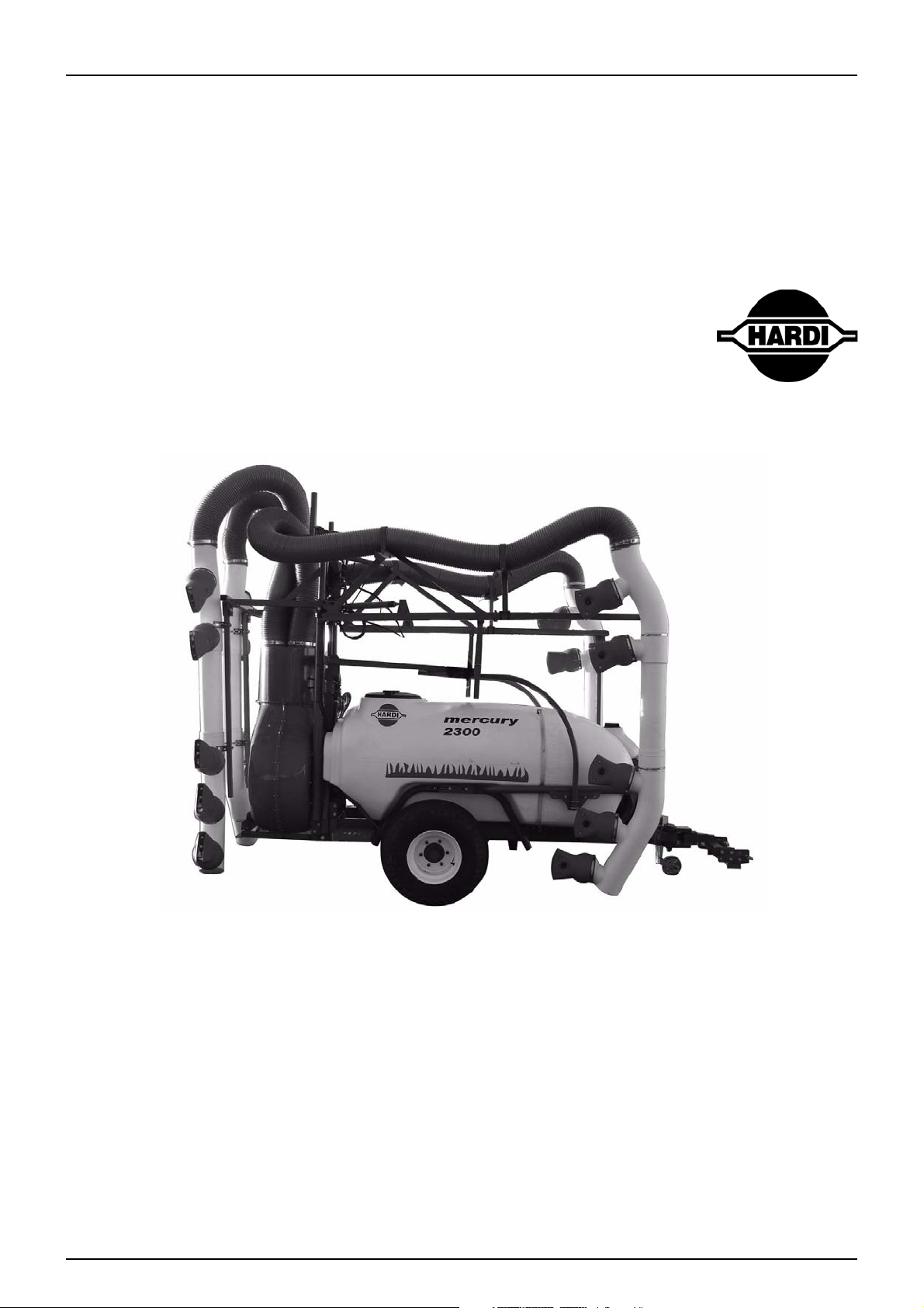
MERCURY COVAMAX
Operator Instruction Manual
67002404- 100
HAU - 08.2009
1 - Welcome
HARDI Australia
534-538 Cross Keys Road Cavan
South Australia, 5094
1. 1
Page 12

1 - Welcome
WELCOME MESSAGE
To our valued customer:
Congratulations on your purchase and thank you for choosing the HARDI “COVAMAX” Mistblower. This “Operator
Instruction Manual” covers the Safety, Operation and Maintenance procedures for the 2300, 3300 & 3800 Litre
models, and is to be read in conjunction with the “Mistblowing Techniques” manual supplied with your sprayer.
This book is not
is to be read in conjunction with the “Spray Technique” book and any other manuals supplied with your sprayer.
WARNING: Any persons intending to use this equipment, or any of it’s parts or systems must read and
±
understand these publications (plus any related material) paying close attention to the safety warnings prior
to operation.
In addition, all operators must be competent, have undergone appropriate training and hold correct licenses
where applicable, as required by state and federal law. The safety sections and warnings in this publication and all
related material must be thoroughly read and understood before attempting to operate this equipment.
DANGER: Failure to comply with the above may result in personal injury, death or damage to the
€
equipment,property, crops or the environment.
Attention: The technical data contained herein is to the best knowledge of HARDI Australia Pty Ltd correct at the time
μ
of publishing. HARDI Australia Pty Ltd reserves the right to make changes in design, features, accessories,
specifications and instructions at any time without prior notice and is without obligation in relation to products
purchased before or after such changes and assumes no responsibility for any errors, inaccuracies or omissions.
Please visit our web site at: www.hardi.com.au for more information about research and development, our
product range, spraying techniques and crop protection. For sales, service and spare parts information contact
your local HARDI dealer.
Copyright: Design, text, illustrations and layout in this manual are produced and published by HARDI Australia Pty
Ltd and are protected by copyright law. Copyright © August 2009 HARDI Australia Pty Ltd.
designed to be a maintenance manual, its main purpose is to supply operational information and
1. 2
Page 13

2 - Safety
Operator Safety
INTRODUCTION
This manual contains safety information which could prevent crop damage, personal injury or death. It is highly
recommended that all operators intending to use this equipment read and understand this manual and related
literature. Safety information in each section must be read carefully, and if any doubt contact your HARDI dealer
for further information.
SAFETY ALERT ICONS
Safety information in this manual is highlighted by the following icons according to the level of potential risk:
DANGER: This indicates the highest level of hazard alert. Failure to comply with the information contained
€
here could result in personal injury or death.
WARNING: This indicates that mandatory action is required. Failure to comply with the information
±
contained here could result in damage to crops, the equipment and/or the environment.
Attention: This indicates practical information regarding safe and effective use of the equipment and its systems.
μ
Note: This indicates general information that can provide the reader with a higher level of understanding.
÷
SPRAY DRIFT
WARNING: Serious crop damage can occur as a result of spray drift. Certain climatic conditions can increase
±
the risk of spraydrift onto neighbouring crops.
Although calibration information is provided in the Mistblowing Techniques Manual it is vitally important that you
read the chemical manufacturer’s recommendations for the correct use of their product.The manufacturers label
will also state the products limitations and warnings.
Wind speed, temperature, humidity and chemical properties should all be considered when determining if
conditions are suitable for spraying. Contact your local Department of Primary Industries for details of relevant
publications explaining the risks and how best to minimise them. It is the responsibility of the sprayer operator to
make sure that the spraying conditions are suitable for the application of the chemical to be used.
WARNING: After changing chemicals or crops it is essential that the entire sprayer be flushed. This includes
±
disconnecting hoses from the filters and pressure relief valve and cleaning residue and sediment in the
hoses, valves and filters. Failure to do so may potentially lead to serious crop damage.
Attention: Remove and store safety wear and clothing after spraying to prevent contamination of the cabin.
±
Dispose of, or clean appropriately. If poisoning occurs identify the chemicals and seek medical advice
urgently.
2. 1
Page 14

2 - Safety
MECHANICAL SAFETY
DANGER: Never operate any part of the equipment if any of it’s components or safety shields are damaged.
€
Never service or repair the equipment while it’s operating and replace all safety devices and shields after
service procedures.
DANGER: Always de-pressurise the equipment and disconnect the power after each use and before
€
servicing. Make sure all hydraulics are in the recommended position. Do not walk under any part of the
sprayer or the boom unless it is properly secured.
DANGER: Never attempt to enter a tank or allow some one else to do so for any reason.
€
DANGER: No persons are allowed in the operations area of the sprayer. Keep unauthorised persons and
€
children away from the equipment at all times. Do not allow any one to ride on the equipment while it is
operating.
DANGER: Do not exceed the max. recommended RPM for any part of this equipment.
€
DANGER: Local laws may require operators to be certified before using spray equipment and some
€
chemicals. Consult your local authorities before commencing operation.
WARNING: When using an arc welder disconnect any power leads to the sprayer prior to welding and remove
±
any flammable or explosive material from the area.
WARNING: Although every effort has been made to include as much safety information as practical, it is
±
impossible to anticipate every hazardous scenario. It is therefore the responsibility of the operator to
exercise safe operating practices.
WARNING: This equipment is intended for the application of crop protection chemicals and liquid fertilisers
±
only. HARDI Australia does not authorise or endorse it’s use for any other purpose.
DISPOSAL OF CHEMICAL CONTAINERS
Please note that in addition to normal safe operating practices, and in the interests of a cleaner and safer
environment HARDI Australia supports the “drumMUSTER” chemical drum recycling program:
• Rinse empty drums immediately after use.
• Remove lids to allow drums to dry completely.
• Recycle with “drumMUSTER”
WARNING: Used chemical containers pose a severe threat to persons, animals and the environment. Before
±
disposal, contact the Environmental Protection Authority or the Department of Primary Industries in your
area for more information.
2. 2
Page 15

2 - Safety
1
2
3
4
5
6
CHEMICAL SAFETY
DANGER: Avoid risk of chemical contamination. Always read chemical labels and pressure test the
€
equipment with clean water prior to filling. Never eat, drink or smoke when spraying or working with
contaminated equipment.
DANGER: Never drink from any of the sprayer's tanks.
€
DANGER: Never assume that the contents of any tank is safe to drink.
€
DANGER: Chemical contamination poses a serious health risk. It is the responsibility of the operator to make
€
sure safe work practices are observed and correct safety equipment and clothing is used.
Safety Equipment
Depending on the type of chemical used, some or all of the
following protective clothing and equipment will be required (see
diagram to right).
1. Hearing Protection
2. Eyes and Face Protection
3. Respirator
4. Chemical Resistant Overalls
5. Chemical Resistant Gloves
6. Chemical Resistant Boots
Contaminated Clothing and Equipment
Contaminated clothing should be carefully removed, safely
isolated and then appropriately laundered or disposed of, taking
care not to contaminate other work areas. Tools and equipment
used must also be safely isolated and carefully washed and
decontaminated.
Australian Safety Standards
Protective clothing and equipment must conform to Australian
Safety Standards and must always be used when handling
chemicals, operating the sprayer and during the cleaning and
decontamination process.
Chemical Information
Always read the chemical manufacturer’s labels as they contain
critical information about your safety and the environment. Always consider the environment when disposing of
chemical residue (see section on decontamination). Chemical labels are registered by the National Registration
Authority. Laws vary from state to state regarding the purpose for which a chemical may be used so consult your
local authorities.
DANGER: Agricultural chemicals can be dangerous. Always read chemical labels and carefully follow safety
€
recommendations to the letter.
Attention: Please refer to the chapter on “Cleaning and De-contamination” in the Operation section of this manual
μ
for further information.
2. 3
Page 16

2 - Safety
SPRAYER SAFETY
Operations
For your safety:
DANGER: Secure the discharge lines before starting the pump. An insecure line may whip causing personal
€
injury and/or property damage.
DANGER: Never operate this vehicle on public roads at high speeds with product in the product tank.
€
Driving at high speeds with product in the tank will overload the tyres, causing tyre failure leading to loss of
control. Losing control can result in death or serious injury.
DANGER: Do not use these pumps for pumping water or other liquids for human or animal consumption.
€
WARNING: Do not pump at pressures higher than the maximum recommended pressure.
±
WARNING: Empty all product from the product tank before leaving the field. Do not attempt to drive this
±
vehicle at high speeds with product in the tank. Fill product tank once you have reached the area of
operation.
WARNING: Turn on the hazard lights and road lights if fitted before entering onto a public road. Keep them
±
on while travelling on the road.
WARNING: Check hoses for wear or worn condition before each use. Make certain that all connections are
±
tightly secured.
Attention: Periodically inspect the product pump and the system components. Perform routine maintenance as
μ
required.
SERVICE AND MAINTENANCE
For your safety:
DANGER: Release all pressure within the system before servicing any component.
€
DANGER: Drain all fluids from the system before servicing any component. Flush with water.
€
WARNING: Disconnect power before servicing.
±
WARNING: Use only pipe, hose and fittings rated for the maximum psi rating of the pump.
±
2. 4
Page 17

ELECTRICAL SAFETY
DANGER
BEWARE OF OVERHEAD
ELECTRICAL LINES
ELECTROCUTION
SERIOUS INJURY OR DEATH
During Sprayer Use
Beware of overhead power lines!
DANGER: Operating agricultural machinery near power-
€
lines presents a potentially fatal hazard. It is the
responsibility of the operator to make sure that minimum
safe clearances are strictly observed, in particular when
transporting the implement, spraying, raising, tilting or
lowering the boom. Also be aware that during hot or windy
weather sagging or swaying of power lines can reduce safe
working clearances.
2 - Safety
Operation of Electrical Components
For Your Safety:
DANGER: Never operate this machine with a damaged electrical cord. Disconnect from electrical supply if
€
machine is not working properly or cord is damaged.
DANGER: Do not attempt to bypass a fuse. If a fuse is no longer serviceable, a shock or short hazard may
€
exist.
DANGER: All electrical components generate heat. To avoid serious burns, never touch internal components
€
immediately after use.
DANGER: Disassembly or attempted repairs, if accomplished incorrectly can create electrical shock and/or
€
short hazards. Only qualified personnel should perform repair service.
DANGER: Some electrical components can store energy after the unit is shut down. Be sure to completely
€
de-energize all electrical components, discharging all stored energy before beginning any service work.
WARNING: Never replace original fuses/breakers with a higher amperage fuses/breakers.
±
WARNING: Never attempt to replace electrical wires and cables with smaller gauge wire and cable.
±
Attention: Do not attempt to operate this machine without the appropriate fuses and breakers in place.
μ
Attention: Inspect all components for damage after any electrical problem.There are additional hazards associated
μ
with the service and maintenance of electrical components
2. 5
Page 18

2 - Safety
2. 6
Page 19
3 - Description
INTRODUCTION
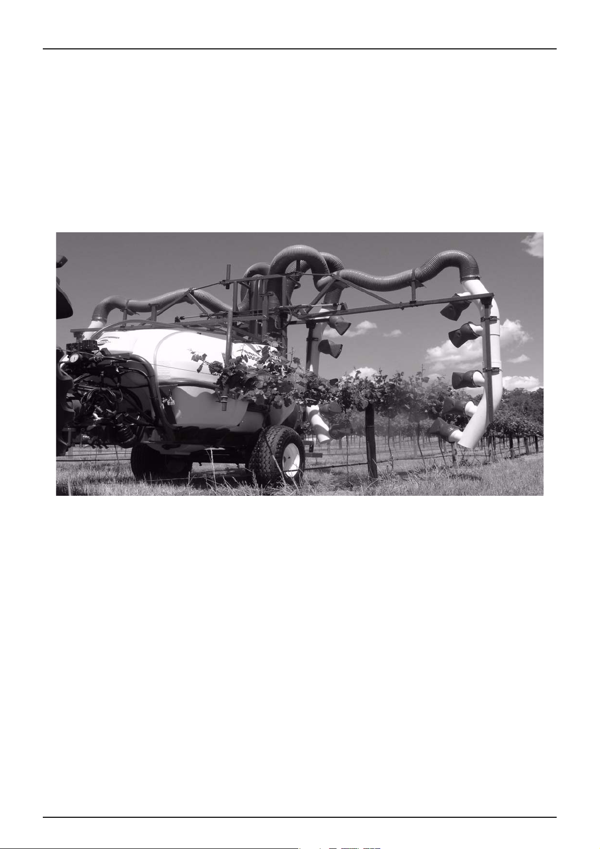
The MERCURY COVAMAX, available in 2300ltr, 3300ltr & 3800ltr models is designed to deliver features that will
enable greater control over your mistblowing needs, while minimising undesirable conditions such as spray drift.
The over row boom completely envelops the vine row delivering superior spray coverage with significantly less off
target drift. The swivel outlets give easy directional control of the spray to the target ensuring converging air
generates the canopy turbulence required for uniform spray deposition.
The COVAMAX is powered by a large fan capacity ducted air delivery system requiring only 35HP to drive. The air
is carried through the 8 inch air tubing which significantly increases air delivery.
The hydraulic boom design is a simple but sturdy construction utilising maintenance free no grease bushes for
trouble free operation. The boom is a perfect platform for supporting the COVAMAX air delivery system. It is width
adjustable and provides for optional wing tilt operation.
Flexibility of the COVAMAX allows the sprayer to be adjusted to suit varying vine canopies. Individual ball in socket
air outlet design provides for smooth rotation and easy adjustment into the right position. Fluid delivery to each
section is activated by its own valve and each air outlet can be independently turned on and off.
Up to five nozzles can be fitted to each outlet, giving a maximum of fifty nozzles per row! This allows the COVAMAX
to be used in both high and low volume application situations.
The MERCURY COVAMAX can be supplied with chassis suspension for smoother ride and a wide angle drawbar for
confined headlands, allowing the sprayer to track directly behind the tractor.
1. 1
Page 20
3 - Description
1
2
4
3
5
6
10
8
11
9
14
13
12
7
GENERAL INFO
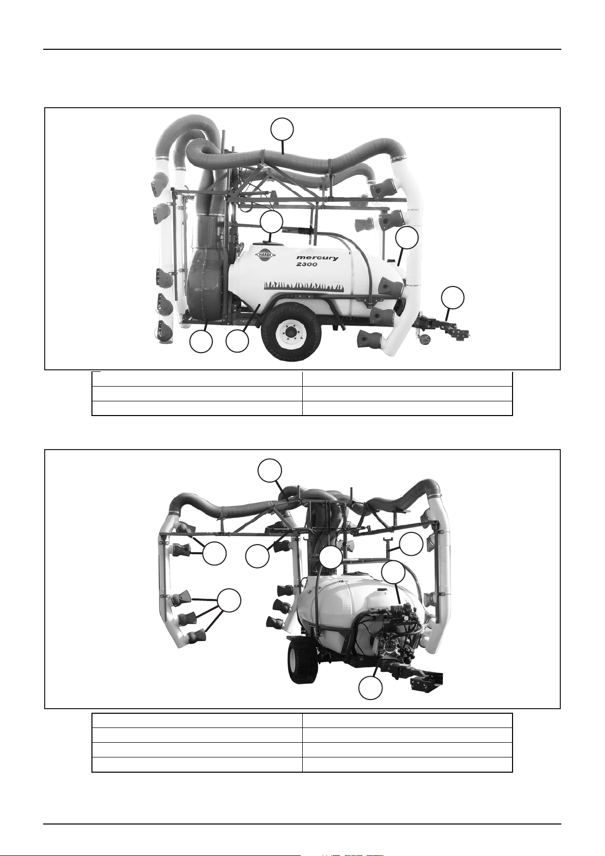
View 1
View 2
1. Boom & Spouts 2. Handwash Tank
3. Drawbar 4. Main Tank
5. Blower Fan 6. Tool Box & Main Tank Lids
1. 2
7. EC Control Valves 8. Tilt Cylinder (If fitted)
9. Upper Nozzle Spouts - Outer Arm 10. Lower Nozzle Spouts - Outer Arm
11. Fold Cylinder 12. Lift Cylinder
13. Boom Transport Brackets 14. Main Pump
Page 21
3 - Description
WORKING ZONEAPPLICATION ZONE
Control Valves
Level Indicators
Handwash Tank
Pressure Gauge
Suction Filter
Pump
Drawbar
PTO Connect
Boom
Tank Lid
Toolbox
Blower Fan
Gearbox
Powder Mixer
Spray Spouts
Pressure Filters
Zone Selection Valves
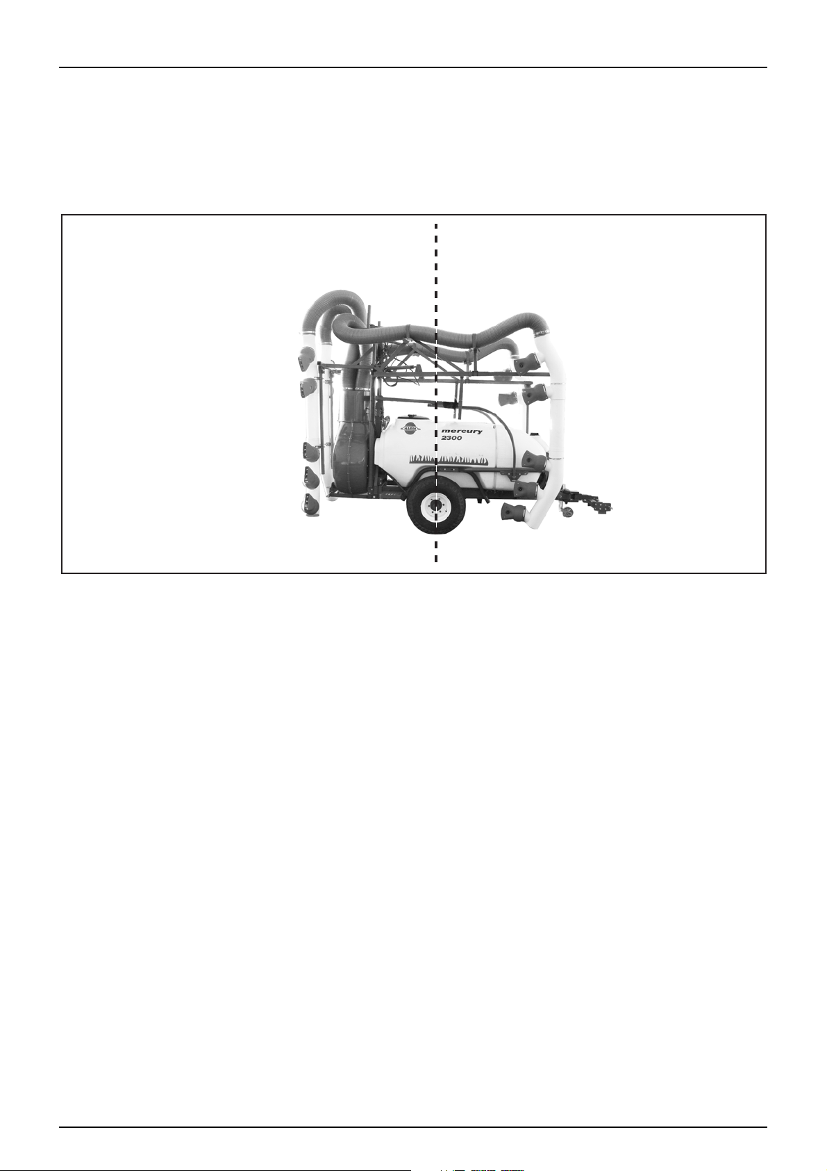
Work Zones
The trailed HARDI MERCURY COVAMAX mistblowers are divided into two different zones.
Working zone: with ease of use in mind; all the elements for regulating the water circuit are located
at the front of the machine.
Application zone: with operator safety in mind; all the parts that come into contact with chemical
products have been located at the rear of the machine.
Sprayer Details
It is important to record details of your sprayer for future reference. These details may help to identify your sprayer
when requiring spare parts or replacement documentation.
Please record your sprayer’s details here:
Model
Serial Number
Capacity
Date of delivery
Dealer
1. 3
Page 22

3 - Description
HARDI INTERNATIONAL A/S
REFERENCE:
Identification Plate
The identification plate is located on the front right-hand side and
is riveted to the frame. The reference number is engraved to aid
identification of the trailer.
The machine number helps to provide details of the trailers history
and equipment fitted for later reference when dealing with issues
such as warranty or spare parts ordering.
Further documents
Upon delivery please make sure your sprayer’s documentation is complete. Your HARDI Dealer should spend time
to check your new equipment with you and give a detailed explanation of the sprayer’s systems and functions.
Please take the time also to fill out your warranty form and return it to HARDI Australia within fourteen days of
delivery.
Road worthiness
When driving on public roads and other areas where the highway code applies, or areas where there are special
rules and regulations for marking and lights on implements, you should observe these and equip implements
accordingly.
Chassis
Manufactured with high tensile profiles which proportion the machine with great durability and resistance to
breakages and vibrations. During the manufacturing process, and to protect it from corrosion, the chassis is first
sandblasted to provide a clean surface, it is then pre-treated by dipping the frame in an iron phosphate bath
followed by a polymer sealant, it is then coated with a poly-zinc protectant and finished with a powdercoat.
1. 4
Page 23
3 - Description
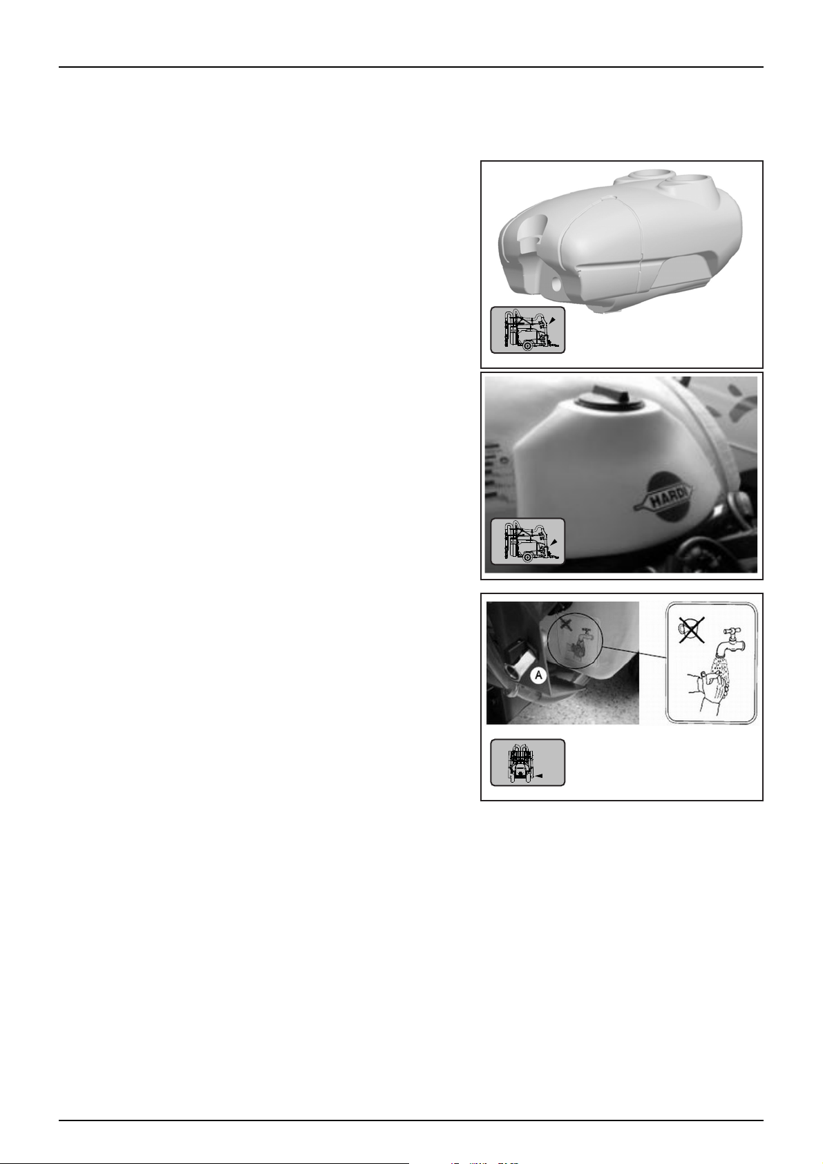
Ta nk s
The COVAMAX mistblowers are available in 3 tank capacities with a range of options, the tank capacities are:
2300 litre 3300 litre 3800 litre
The tanks are made of a UV, chemical and Impact resistant
polyethylene. The main tank is designed for easy cleaning and
rounded corners to aid agitation and prevent chemical from
becoming trapped in tight spots.
The main tank also features a fluid level indicator.
The Handwash tank has a nominal capacity of 15 litres. and is
situated at the front of the sprayer. The outlet for the handwash
tank is located at the lower left hand area of the main tank just
behind the suction filter.
DANGER: The “clean water” tank is intended for hand washing etc. only and must not to be used for drinking
€
water.
1. 5
Page 24
3 - Description
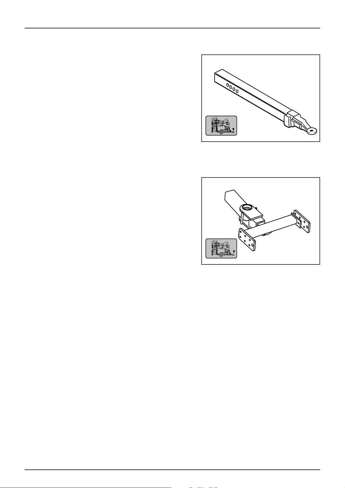
Drawbars
Standard Duty Wide Angle Drawbar
The standard drawbar is coupled to the tractor’s hitching point.
Before connecting the PTO make sure that the drawbar is properly
secured and check that the tractor’s wheels do not touch the
mistblower when turning. The length of the drawbar is adjustable
(see Sprayer Setup section for “Changing the drawbar length”).
Attention: Before connecting the PTO make sure that the
μ
diameter and number of splines on the driveshaft is the
same as that of the tractor’s output shaft. Make sure that the
tractor’s PTO output speed is matched to the speed of the
product pump.
Heavy Duty Wide Angle Drawbar
This drawbar is coupled to the tractor’s linkage.
Check that the tractor’s wheels do not touch the mistblower when
turning. Unlike a standard drawbar, it permits greater turning
angles, but a transmission shaft with CV joint is needed on the
mistblower side.
The length of the drawbar is adjustable (see Sprayer Setup section
for “Changing the drawbar length”).
1. 6
Page 25
3 - Description
BHS200 Product Pump
363 Product Pump
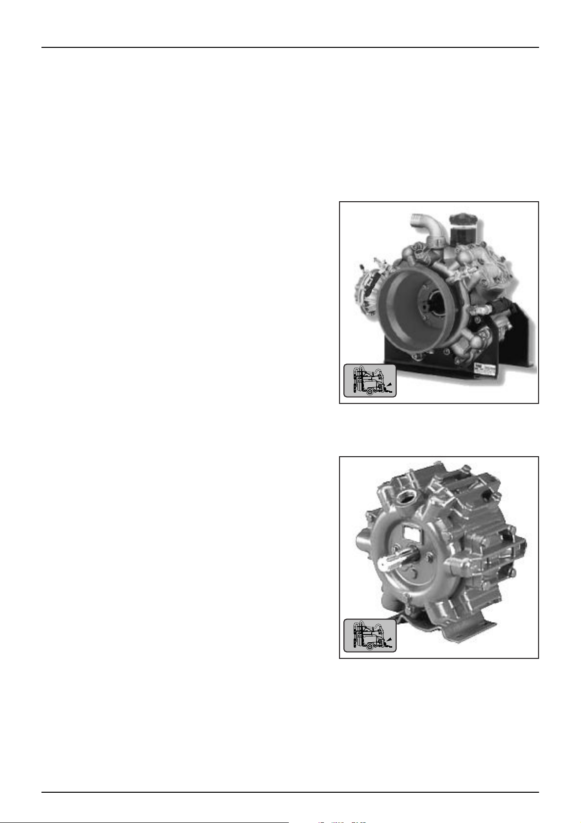
Fluid System
Main Product Pump
The main product pump is available in two different models;
• AR Pumps BHS200 - Four Diaphragm Brass Head High Pressure Pump
• HARDI 363 - Six Diaphragm Positive Displacement Pump
BHS200 Pump
High pressure diaphragm pumps with positive displacement, external bronze manifolds and brass heads with 4
diaphragms. It has a maximum pressure of 50 bar (775 PSI) and operating at 550 RPM will deliver 193.7 litres per
minute.
• Four diaphragm positive displacement pump
• High Pressure 50 bar (725 PSI)
• 193.7 Litres per min delivery rate.
• Self priming
• Oil bath lubrication
• Cast alloy construction
363 Pump
The Hardi 363/7 pump has a 6 splined 1 3/8” shaft for connection to the tractor PTO. The normal operating
revolutions are 540 RPM. The HARDI 363 is a self priming diaphragm pump with 6 diaphragms and a maximum
pressure of 20 bar (294 PSI).
• Six diaphragm positive displacement radial pump with base
plate.
• Self-priming.
• Can rotate clockwise or anti-clockwise.
• One grease point for lubrication.
• Dry sump to simplify maintenance.
• Polyurethane diaphragms and seals.
• Cast iron crankcase and covers.
• Stainless steel bolts and plates for diaphragms.
• 1 1/2” suction port, 1” pressure port.
• Capacity range of 140 l/pm @ 0 bar to 122 l/pm @ 20 bar
1. 7
Page 26
3 - Description
Fluid Manifold System
Control of the fluid flow and functions is carried through a distribution manifold. This manifold consists of control
valves (MC/2, CB/2 or EVC), pressure regulators, flowmeter (option), pressure relief and control taps for activation
of agitation and if fitted the powdermixer option.
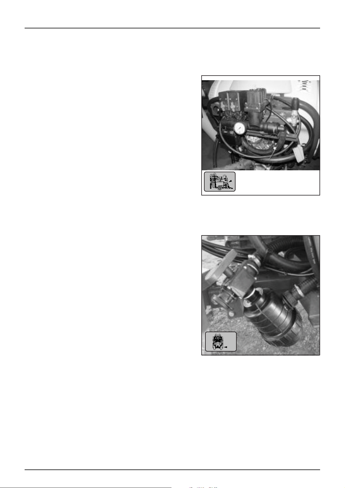
Filters
The filters fitted to the MERCURY COVAMAX include a suction filter and two optional pressure filters;
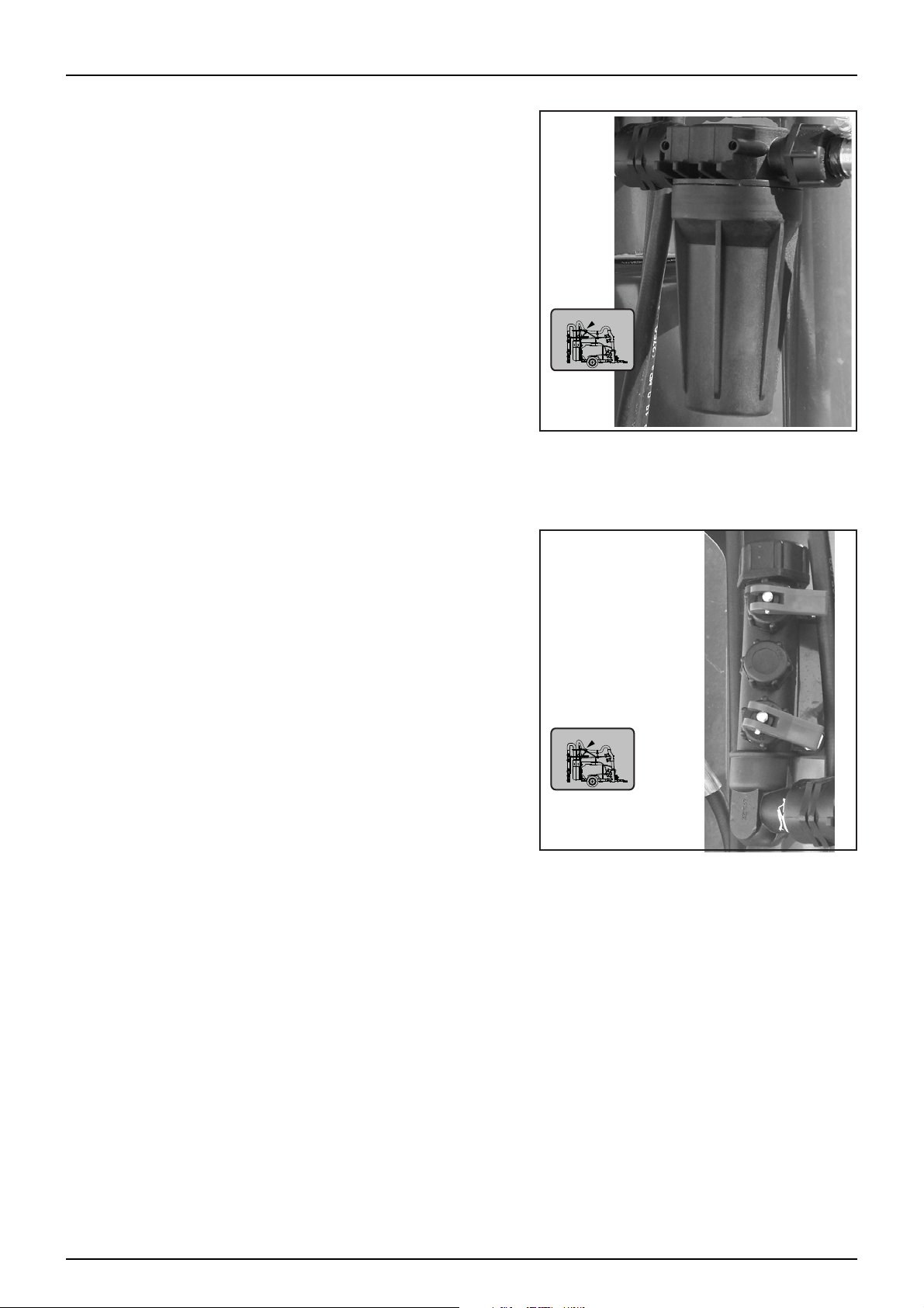
Suction Filter
The suction filter captures impurities in the liquid system in order to protect the machines’ components. It is
located at the front of the sprayer in the lower left hand side next to the main pump.
The tap on the top of the suction filter controls the selection source for fluid flow. The source tap can be turned to
open the valve to accept an external source supply or to supply from the main tank contents, the tap may also be
turned to an ‘OFF’ position by turning the handle to 90 degrees between the two source options for servicing the
filter when the tank has liquid inside.
1. 8
Page 27
3 - Description
x2
x2
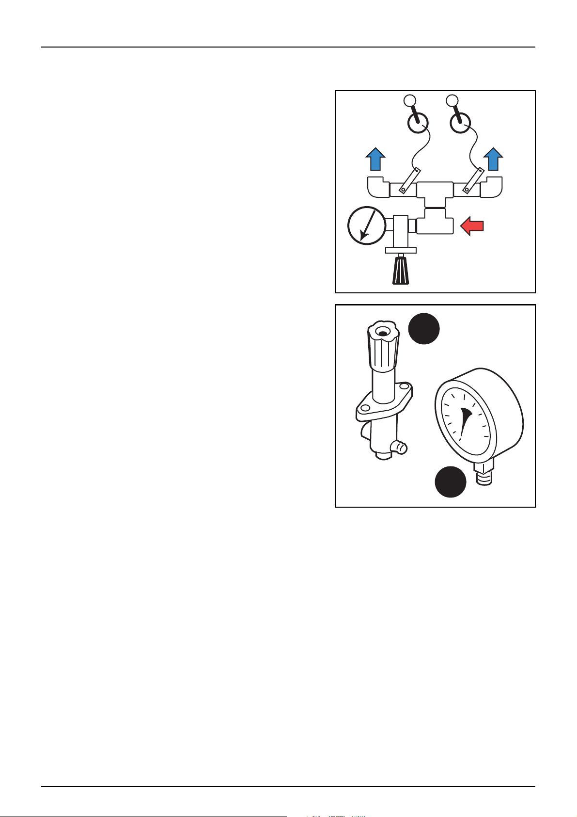
Pressure Filters (Optional)
The sprayer is fitted with two inline pressure filters which
independently filter each side of the boom. These filters are
located directly in front of the fan and are connected immediately
before the boomzone selection valves.
BoomZone Selection Valves
Located immediately after the pressure filters are valves that control the flow to the boom sections. Each valve
controls flow to the left and right side - inner or outer boom sections.
1. 9
Page 28
3 - Description
1
2
Operating Units
MC/2 Manual Operating Unit
The MC/2 Manual operating unit consists of a pressure valve (1)
and a pressure gauge (2). These are connected on to the end of the
supply manifold and serve to regulate and read the system
pressure.
With the use of two control handles connected to the tractor’s
cabin, control of the left and right side spray zones can be
manually operated as required.
1. 10
Page 29
CB/2 Electric Control Unit
Brown wire (+)
Blue Wire (-)
12V
+
-
1
2
3
4
5
Through an electrical control box the incorporated switches are
operated to select the sector that you want to open, and to raise or
lower the pressure.
Its constituent elements are:
• Pressure Gauge
• Electro Valves for section control
• Electro Valve for pressure control
• Spray Box 2 (pressure, section ON/OFF)
• Pressure Equaliser Valves
The power requirement is 12V DC. Be very careful with the
μ
po la rity as ther e i s a ris k of da ma ging the circuit of the control box
or some of the electro-valves.
3 - Description
1. 11
Page 30

3 - Description
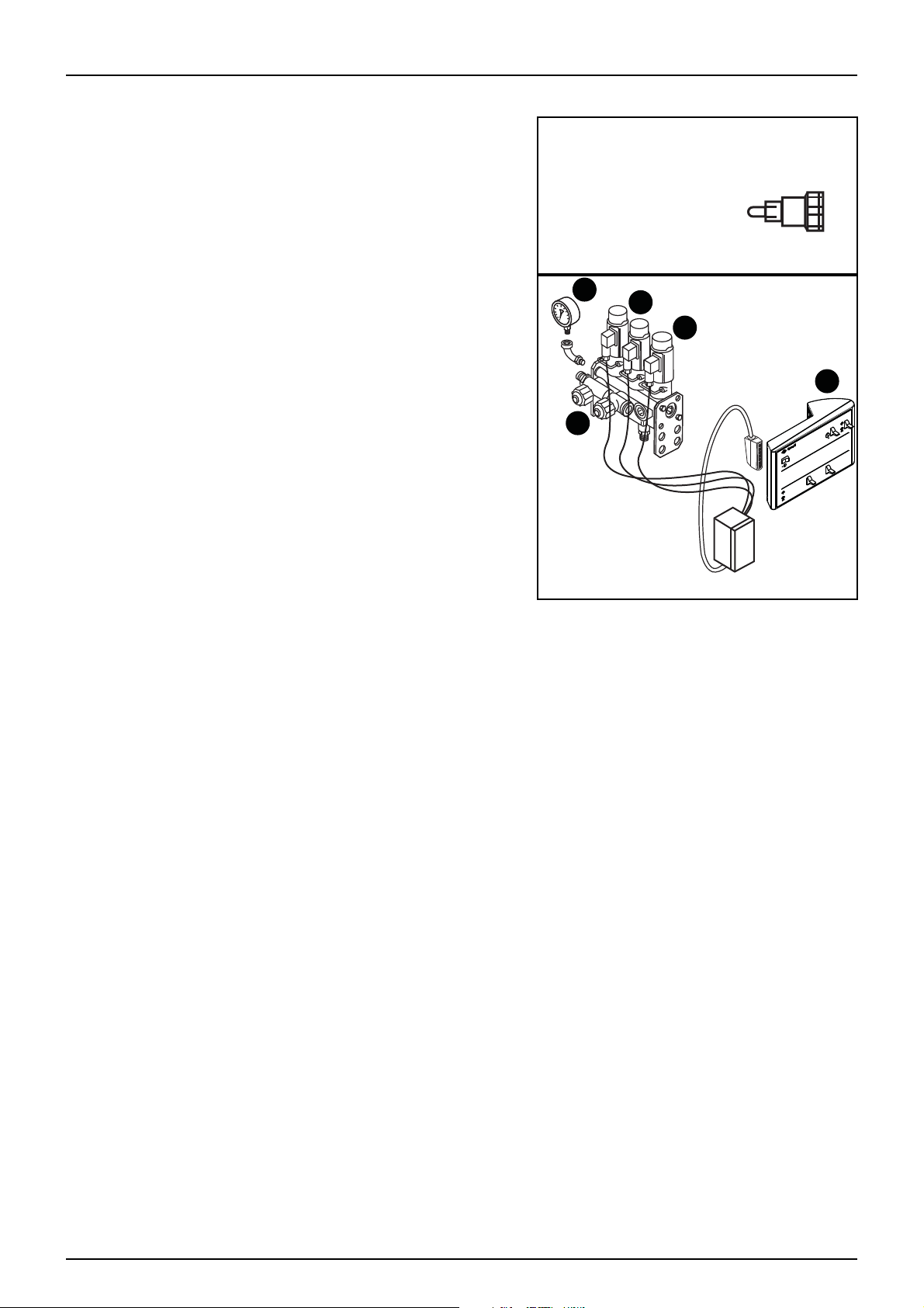
EVC Operating Control Unit
The EVC control unit is constructed of modules and consists of;
• Pressure Relief Valve
• Pressure Regulator
• Pressure Gauge
• Flowmeter (fitted on electronic control)
• Section distribution valves
• Constant Pressure Equalisation valves
Pressure Relief valve
The pressure relief valve mounted to the end of the fluid
distribution manifold enables control of the maximum liquid system pressure.
EVC Pressure Regulation Valve
The pressure regulator controls the system pressure allowing excess fluid to bypass back to the main tank.
Pressure Gauge
The pressure gauge gives a visual indication of the system pressure and can easily be viewed from the tractor cab.
Section Distribution Valves
The distribution valves offer independent control of fluid flow to the boom sections enabling operation of either
left wing, right wing for versatile application of chemical product.
Constant Pressure Equalisation Valves
Mounted underneath the distribution valves is an adjuster that controls the constant pressure for the distribution
valves, this helps to maintain a constant system pressure when the distribution valves are opened or closed.
1. 12
Page 31

HARDI Spray 2 Switchbox
The Spray 2 controller is connected in combination with either the
HC 2500 or the HC 5500 and allows for operator control of spray
zone selection and remote pressure regulation
Automatic Rate Controller Options
HC 2500 Display
The HC 2500 display provides user feedback of spray application in
addition to visual and audio alarms that notify the operator when
conditions have changed
HC 5500 Display
3 - Description
Like the HC 2500, the HC 5500 display gives valuable feedback to
the operator. The HC 5500 offers more control for features such as
application rate programmability, preset keys, remaining volumes,
etc
Note: Please refer to the seperate operator instruction
÷
manuals that are supplied with your controller options for
detailed information on controller usage.
1. 13
Page 32

3 - Description
AIR INLET
AIR INLET
Air Flow Delivery System
The air flow delivery system includes the following;
• Centrifugal Blower Unit
• 4-way Distribution Stack
• Flexible Delivery hoses
• Boom delivery tubes
• Outlet Delivery Spouts &Nozzles
Centrifugal Blower Unit
The MERCURY COVAMAX is fitted with an HF600 Twin Row
Centrifugal Blower. The blower turbine wheel is a robust, onepiece design made from aluminium. The blower unit draws air
from both sides of the turbine wheel and supplies an air flow of
25000 m3/h which is delivered to a 4 distribution stack.
The blower unit is speed controlled via the gearbox and PTO revs,
it delivers air through the distribution stack and out to the boom
nozzles.
The blower unit draws air from the front and rear of the machine
that is then divided and directed into the boom tubes by the
distribution stack.
Warning: Do not put hands or other objects near fan. Fan
±
operates at high speeds and can draw nearby objects into
the blower intake.
Warning: Wear approved hearing protection when
±
operating blower unit.
4-Way Distribution Stack
The 4-way distribution stack separates the airflow from the blower
unit and evenly distributes it to the boom tubes
Flexible Delivery Hoses & Boom Tubes
The flexible delivery hoses enable boom movement and air
delivery to the boom tubes. The boom tubes are adjustable to suit
the required vertical placement of nozzles, they also support the
nozzle assemblies.
Outlet Delivery Spouts & Nozzles
The outlet spout assemblies provide the operator with individual
ON/OFF nozzle capability in addition to individual positioning of
the spouts to enable directing of spray output.
1. 14
Page 33

3 - Description
1 2 3
Gearbox
Warning: Make sure that PTO shaft has come to a complete
±
stop before changing gears on gearbox
Fitted to the MERCURY COVAMAX is a two speed gearbox. This gearbox is mounted directly in front of the fan unit
and controls fan speed between the PTO shaft and the blower by positioning the lever in one of three positions;
• Position 1 -Slow speed 540/1890RPM (1:3.5 Ratio)
• Position 2 - Neutral (disengaged drive)
• Position 3 - Fast speed 540/2380RPM (1:4.4 Ratio)
1. 15
Page 34

3 - Description
STANDARD BRAKED
STANDARD
STEPPED BRAKED
STEPPED
Axles
Axle options for the MERCURY COVAMAX are either in the form of a straight axle or a stepped axle and vary
depending on sprayer size.
The straight axle is adjustable for track width and for placement forward and aft on the sprayer.
The stepped axle provides the same adjust ability as the straight
axle but with the stepped axle further changes to ride height can be made with the repositioning of the axle to
enable higher ground clearance if desired.
The half-axles are mounted in a housing that
is bolted to the frame. This has five different
settings to improve the stability of the
machine when necessary.
Track Adjustment
In order to obtain a wider track gauge or
greater stability on sloping terrain it is
possible to lengthen the half-axles of the
HARDI MERCURY mistblower on all its
versions.
DANGER: Raise the mistblower frame and prevent it from moving. Carry out this operation with empty tanks.
€
•Loosen the nuts and bolts on the axle housing.
•Extend the half-axle to the desired length without exceeding the maximum.
•Tighten the nuts and bolts again until the half-axle is sufficiently secured.
•Make sure that the two axles have been lengthened to the same amount in reference to the centreline of
the sprayer.
1. 16
Page 35

3 - Description
LIQUID FILLING NOT ALLOWED
WITH IMPLEMENT TYRES PROVIDED
Wheel Types
HARDI MERCURY COVAMAX mistblowers possess a wide range of interchangeable wheels to make it possible
to adapt the equipment to the particularities of the terrain.
Warning: The mistblower’s wheels are IMPLEMENT type and
±
cannot exceed 40 km/h. when fully loaded.
Warning: Tyres MUST NOT BE LIQUID-FILLED.
±
HARDI will not be held responsible for the consequences or
damage that this practice may have on its mistblowers.
Note: Always maintain the recommended pressure to get
÷
normal wear and life from the mistblower’s wheels, and to
avoid punctures and unnecessary strain.
Wheels & Tyres
A 12.5/80 x 15.3 x 14 PLY Std on 2300l
A 12.5/80 x 15.3 x 14 PLY Std on 3300l
B 400/60 x 15.5 x 14 PLY Std on 3800l
Options for 3800l
C 400/55 x 22.5 x 14 PLY (Flotation Tyre)
In areas of difficult access with many slopes, or for working on tall crops, always choose a wheel that guarantees
sufficient ground clearance.
The mistblowers tyres should always be at the correct pressure as they act as a suspension system when the tank
is full, making the whole assembly less rigid. Refer to the tyre pressure specified by the tyre manufacturer when
inflating.
1. 17
Page 36

3 - Description
ACTIVE SUSPENSION PASSIVE SUSPENSION
Suspension
The frames of Covamax machines can be fitted with a unique and exclusive torsion suspension system that is
capable of smoothing and absorbing irregularities in the terrain. This system improves safety on long trips over
rough terrain and reduces time spent on trips for filling, etc...
The suspension is ACTIVE when the machine is load-free, and it gets lower as the tank is filled. When the tank of the
mistblower reaches half-full, the suspension is PASSIVE, as the machine will only tilt if there is a very pronounced
unevenness in the terrain.
Note: Use of the suspension with the ring drawbar is recommended for those machines which frequently
÷
cover long distances over uneven terrain.
1. 18
Page 37

Powder Mixer - Chemical Induction
Agitation
Powder Mixer
Not Used
3 - Description
The powder mixer option supplies liquid to an outlet in the base of the powder mixer basket, this helps to dissolve
dry chemical in the basket.
DANGER: Do not operate the powder mixing feature with the lid removed as chemical product may be forced
€
from the basket and cause chemical contamination to surrounding areas or contact with operator.
Activate the powder mixer by turning the tap handle for powder mixing ON when the pump is running, this will
draw main tank liquid through the manifold and into the powder mixer basket. Turn the tap OFF when not in use.
1. 19
Page 38

3 - Description
Boom
The boom fitted to the MERCURY COVAMAX has numerous features that enable flexibility for operators when
setting up and operating. Some of the benefits are;
• Lift
• Fold
• Tilt
• Breakaway Arms
• Adjustable nozzle positioning and directing
• Low maintenance
1. 20
Page 39

3 - Description
Lift
The lift mechanism consists of a single double acting cylinder with two telescoping uprights that support and
guide the boom centre
Fold
Boom folding is independently operable through two double acting cylinders enabling the flexibility to open and
close boom wings for one side at a time.
Til t
The MERCURY COVAMAX has two options available for tilting of the boom;
• Electric over Hydraulic (EOH)
• Manual Hydraulic
Electric over Hydraulic (EOH)
The electric tilt option allows independent tilting of the boom wings and connection to the tractor using fewer
hydraulic outlets
Manual Hydraulic Tilt
Manual Hydraulic Tilt is available as an option to perform actions similar to the electric tilt option, however the
manual tilt option requires the use of two additional hydraulic circuits on the tractor.
1. 21
Page 40

3 - Description
ON/OFF VALVE
Breakaway Arms
To minimise damage to equipment or crops should the boom
collide with an object, a breakaway feature is incorporated into the
boom. A pivoting hinge mounted on a rear spar of the boom centre
allows the boom tubes to independently move out should the
boom arm come in contact with an object.
Adjustable Nozzles & Independent control
The nozzle bodies fitted to the Covamax allow for greater control
of fluid flow and spray dispersion.
Each nozzle body contains an ON/OFF valve that enables liquid
flow to be stopped at the nozzle manifold in each nozzle body.
1. 22
Page 41

4 - Set Up
Sprayer Set-Up
Introduction
This section of the manual deals with taking delivery and preparing the new sprayer for service in the field. It
contains important information to help you get started, plus mandatory safety information. Please make sure that
anyone intending to use the equipment carefully reads and understand the contents, plus any related
documentation.
Safety
Safety during set-up, service and maintenance procedures requires awareness, preparation and common sense.
μ
Preparing the sprayer for service in the field involves:
• -Unloading the sprayer from transport
• -Connection and testing of Mechanical components
• -Connection and testing of Electrical wiring and systems
• -Connection and testing of Hydraulic hoses and systems
• -Installation of mounting brackets and electronic components in the cabin
• -Reading and interpreting technical information and illustrations
• -Testing of Fluid systems
Below is a list of safety issues which must be observed before commencing set-up:
Before carrying out any set-up procedures observe the following:
• -Make sure your work area has lifting and safety equipment of a suitable load bearing capacity.
• -Always wear safety eye protection, overalls, safety boots and gloves where appropriate.
• -Keep animals and people away from the service area at all times unless involved in the procedure.
• -Keep children away.
• -If necessary clean and de-contaminate the sprayer and use chemical safety gear (see “Chemical Safety”
section 2).
• -Position the sprayer on a suitable flat surface with enough room for the boom to operate.
• -Never perform set-up, service or maintenance procedures with the engine or PTO running.
• -Turn the tractor engine off, place in park with the hand brake on and remove the ignition key!
• -Fit wheel chocks in front and behind of each wheel.
• -Always use suitable safety stands when supporting the sprayer off the ground.
• -Always re-fit all safety equipment and shields after service procedures.
• -Think each job through before commencing work and assess any potential risk.
• -Avoid working alone or at least have some-one check on you periodically.
• -Carry a mobile phone on you for emergencies.
• -Isolate any power source and clear the area of any flammable material before using an arc welder.
• -If any procedure is unclear or requires facilities which are not available, refer the job to your HARDI dealer.
4. 1
Page 42

4 - Set-Up
Transporting Mistblower
Truck transport
Preparing Mistblower for transport
To prepare the mistblower for transport consider the following points;
• Mistblower is emptied
• Mistblower is clean and decontaminated
• Items such as boom arms are secured to prevent movement during transit
• Carry out visual inspection to make sure that no items can come loose during transit
Securing Mistblower for transport
When secur ing the m istbl ower on to a truck trailer, ma ke sure the trailer is of adequate size and properly placarded
with safety signs should they be required.
Do not allow heavy objects to be loaded on top of the mistblower as this may cause damage to mistblower
components or surface finishes.
Tie down the mistblower adequately to prevent movement during transport.
Loading or Unloading the mistblower from a truck
When loading or unloading the mistblower from a truck trailer with the aid of a block and tackle or crane, use the
lifting points shown in the illustration, and make sure that the straps or cords used for the purpose are strong
enough and comply with Australian Safety Standards.
4. 2
Page 43

Connecting Mistblower to tractor
B
C
A
Connecting the mistblower requires the following;
• Adjusting drawbar length
• Hitching drawbar to tractor
• Connecting hydraulics to tractor
• Sizing & Fitting PTO shaft
• Un-mounting Jockey Wheel
• Connecting control box (if fitted)
Adjusting drawbar length
Both drawbar designs have the ability to be adjusted. The basic steps to follow are;
• Support mistblower on jockey wheel
• Loosen bolts (C) where the drawbar passes through the
chassis
4 - Set Up
• Remove nut & bolt (B)
• Slide drawbar in or out of the frame to desired position
• Refit nuts & bolts (B) and tighten lockbolts (C) sufficiently to
prevent movement
Additional adjustments can be made by altering hole positions of plates (A) on wide angle drawbar
Attention: Make sure the bolt passes through both the holes in the frame and the holes in the drawbar as shown (B)
μ
and that locknuts (C) are securely tightened.
4. 3
Page 44

4 - Set-Up
Hitching Drawbar
Depending on the type of drawbar fitted to your sprayer, one of two connection methods will be used;
• Standard Drawbar - direct connect to trailer hitch
• Wide Angle Drawbar - connected to linkage arms
Standard Drawbar
The standard drawbar is hitched to the tractor and secured with a
pivot pin
Wide Angle Drawbar
The wide angle drawbar is directly connected to the linkage arms
which can be used to change the sprayer height for levelling the
mistblower.Of the two hitch types this is the one that permits the
greatest turning angles.
4. 4
Page 45

4 - Set Up
Sprayer levelling with wide angle drawbar
By having the drawbar hitched to the tractors linkage arms it provides the ability to level the sprayer as shown
below, this will provide a better ride and more accurate readings when using items such as the sight gauge.
4. 5
Page 46

4 - Set-Up
Connecting Hydraulics
The hydraulic hoses supplied with your mistblower will vary depending on the options you have fitted. As a
standard there will be six hydraulic hoses supplied, two will control the boom lift function and four for the
independent boom fold functions. There is also the possibility of a further four hoses that control hydraulic tilt
function if it has been fitted to your machine.
If Electric over Hydraulic (EOH) Tilt is fitted as an option, the supplied number of hydraulic hoses is reduced to only
four hoses, two hoses control the boom lift function and two supply the EOH hydraulic manifold, the EOH
switchbox controls operate the independent boom fold and tilt operations through electronic control of hydraulic
solenoids.
Connect the required hoses into the hydraulic outlets on the rear of your tractor. The cylinders used for lift, fold and
tilt features all require double acting hydraulic outlets.
Hydraulics hoses are marked for identifying which hoses are for
which function. They are generally labelled with either named tags
(lift/fold/etc) or have different coloured cable ties attached to the
hoses as shown. For each cylinder one hose connects to the
pressure line (P) and the other connects to the tank line (T).
4. 6
Page 47

4 - Set Up
PROPORTIONAL BRAKE OUTLET
LEFT/RIGHT DISTRIBUTION
MISTBLOWER
BRAKE ASSEMBLY
PISTON
SUPPORT
BRAKE LEVER
AXLE ROD
DIRECTION
BRAKE SHOE DIAGRAM
TRACTOR
OPTION 1. Quick ttings
Tractor
male
Mistblower
female
Protector nut
Brakes
Brakes are available for all MERCURY COVAMAX models, it consists of a hydraulic braking system with two options
available to stop the mistblower.
Tractors with a proportional brake outlet are suitable for the
mistblower’s hydraulic braking system, because they permit
progressive braking before the wheels are blocked in the case of
emergency.
Attention: The tractor’s proportional outlet should be adjusted to
μ
a maximum of 150 bar (2175 p.s.i.).
4. 7
Page 48

4 - Set-Up
DANGER
ROTATING DRIVESHAFT
SERIOUS INJURY OR DEATH
Do not operate without guards tted
or driveshaft connected at both ends
Make sure guards turn on driveshaft
Inspect driveshaft daily
Fitting PTO Shaft
In order to maintain drive to the sprayer’s pump whilst allowing for changes in length the transmission shaft is
divided into two halves with matching profiles.
The geometric shape of the profiles locks them together on the rotational axis whilst allowing free lateral
movement to absorb changes in length as the implement and tractor move in relation to each other.
Transmission Shaft - Operator Safety
• Always STOP ENGINE before attaching the transmission shaft to tractor P.T.O. - most tractor P.T.O. shafts can
be rotated by hand to facilitate spline alignment, when engine is stopped.
• When attaching the shaft, make sure that the lock is FULLY ENGAGED - push and pull shaft until it locks.
• Always keep protection guards and chains intact and make sure that it covers all rotating parts, including CV-
joints at each end of the shaft. Do not use without protection guard.
• Do not touch or stand on the transmission shaft when it is rotating - safety distance: 5’ (1.5 meter)
• Prevent protection guards from rotating by attaching the chains allowing sufficient slack for turns.
• Make sure that protection guards around tractor P.T.O. and implement shaft are intact.
• Always STOP ENGINE and remove the ignition key before carrying out maintenance or repairs to the
transmission shaft or implement.
DANGER: ROTATING TRANSMISSION SHAFTS - DO NOT USE WITHOUT PROTECTION GUARDS.
€
DANGER: PTO SHAFTS CAN SERIOUSLY INJURE. KEEP CLEAR OF ROTATING PARTS!
€
Transmission Shaft - Installation
First installation of the transmission shaft is done in the following way:
• Attach sprayer to tractor and set PTO angle to a maximum of 15 degrees, position with shortest distance
between the tractor and sprayer pump P.T.O. shafts.
• Stop engine and remove ignition key.
• If transmission shaft must be shortened, the shaft is pulled apart (see PTO Shaft Length reduction)
WARNING: The shaft must always have a minimum overlap of 30%.
±
• The PTO shaft connects between the tractor output spline and the pump input spline.
4. 8
Page 49

PTO Shaft length reduction
x
x
min. 20mm
1/3 1/3 1/3
A B C D E
A. Universal joint
B. Safety guard
C. Female section
D. Male section
E. Splined coupling
WARNING: The shaft must always have an overlap (A) of
±
minimum 1/3 of the length.
Fit the two shaft parts at tractor and sprayer pump and measure
how much it is necessary to shorten the shaft. Mark the protection
guards.
• The two parts are shortened equally. Use a saw, and file the
profiles afterwards to remove burrs.
• Grease the profiles and assemble male and female parts
again.
• Fit the shaft to tractor P.T.O. and sprayer pump shaft.
• Fit the chains to prevent the protection guards from rotating
with the shaft.
4 - Set Up
• To ensure long life of the transmission shaft, try to avoid
working angles greater than 15°.
4. 9
Page 50

4 - Set-Up
Position 1
Position 2
Jockey Wheel
The jockey wheel allows the mistblower to be coupled to or
uncoupled from the tractor. It should be in position 1 when the
mistblower is uncoupled, and in position 2 when it is coupled to
the tractor. In this position the jockey wheel is fixed to the
mistblower’s frame by two spring pins.
The jockey wheel is secured in place with two pins that enable it to
be fixed to the frame and held with two spring clips.
The height of the machine can be altered by turning the handle of
the jockey wheel.
Drawbar Safety Chains
Due to weight distribution when the MERCURY COVAMAX is
working in the unfolded position, a chain and brace is fitted to the
wide angle drawbar to prevent the sprayer from tipping up when
rearward weight conditions are present.
The brace is attached to the side plates of the drawbar hitch and a
chain with shackle is connected to the rear of the tractor.
Maintain enough slack in the chain to prevent it from binding
during operation but taught enough to perform the task.
Isolate the hydraulic linkage arm lifting mechanism after chain is
fitted to the top link pin.
Warning: Operation of the hydraulic 3 point linkage arms
±
lifting mechanism after the chain has been fitted will cause
the brace to bend or tractor link arms to reach stall point in
hydraulics and may cause damage to the sprayer or tractor.
4. 10
Page 51

4 - Set Up
Connecting Controls
The following optional extras will all require further setup and connections between the mistblower and the
tractor;
• Electric over hydraulic tilt
• EVC & CB/2 fluid control
The control box options to accompany these extras are;
• HC2500
• HC5500
Note: Please refer to the controller specific handbook supplied with your sprayer for detailed information on
÷
connection and operation.
Electric over Hydraulic Tilt
Th is o pti ona l ex tra allows the til t an d fo ld f unc tion s of the boo m to be r emo tel y cont rol led fro m th e tr actor c ab a nd
to reduce the number of hydraulic hose connections at the tractor, this may be useful when there are not enough
outlets available for connecting manual tilt hydraulic control.
EVC Fluid Control
Connection for HARDI EVC or Braglia CB/2 controller options is via a 39 pin plug which connects directly to either
a HC2500 or HC5500 HARDI Controller
4. 11
Page 52

4 - Set-Up
HARDI Spray2 Switchbox
The HARDI Spray2 Switchbox is used for the control of fluid in
conjunction with the EVC fluid components and CB/2
The Spray 2 controller is connected in combination with either the
HC 2500 or the HC 5500 and allows for operator control of spray
zone selection and remote pressure regulation
HC2500 & HC5500 Displays
The HC 2500 and HC 5500 displays offer spray data to the user
depending on which transducer options are fitted to the sprayer.
Note: Please refer to the controller specific handbook
÷
supplied with your sprayer for detailed information on
connection and operation.
4. 12
Page 53
Boom Adjustments
Boom Width Adjustment
Crop Height Adjustment
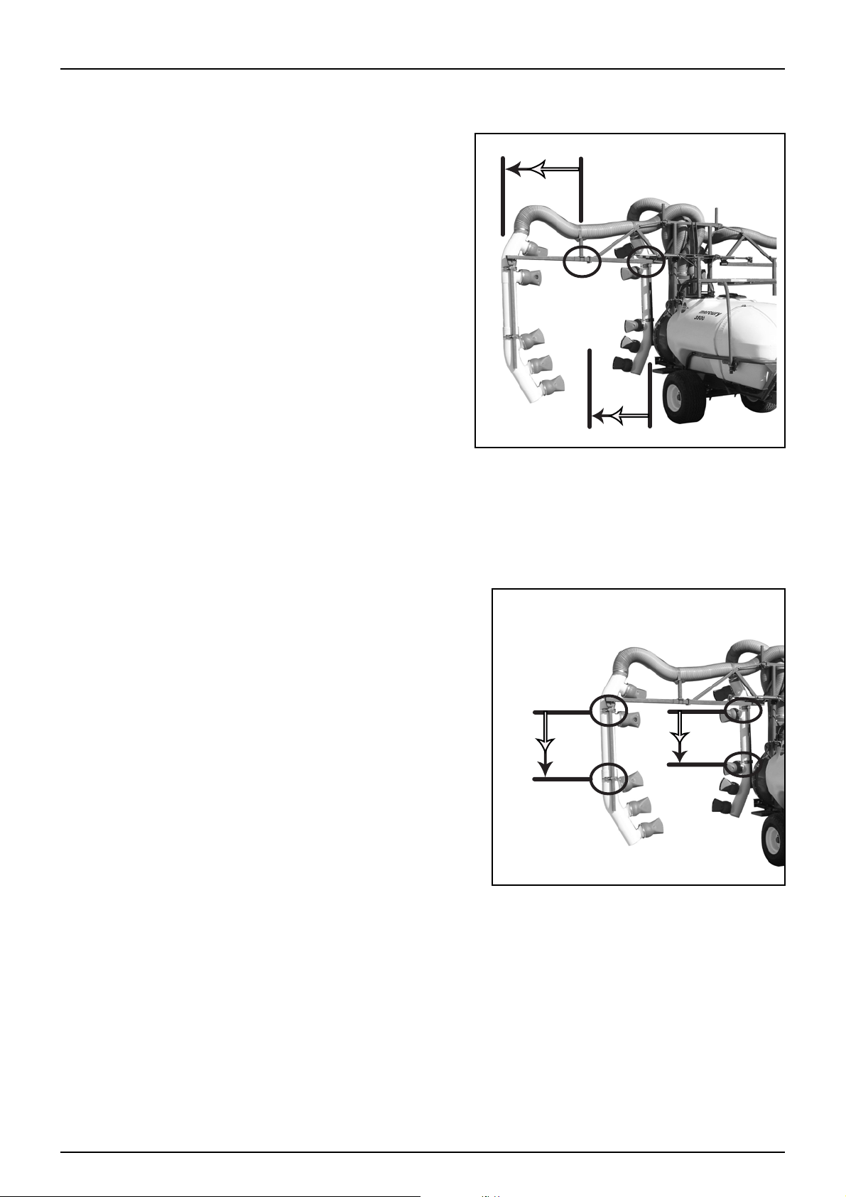
Boom Width - Row Spacing
The position of the out reaching arms can be regulated to alter
the width of the boom, in order to adapt the machine to match
the row spacing. Adjustment is achieved by loosening clamps
on the horizontal bar and extending or shortening the
telescopic tubes to the desired width. Once the required
position has been chosen retighten clamps to prevent any
movement of the bar.
4 - Set Up
Note: Both the inner and outer boom sections may be repositioned to suit user requirements.
÷
Crop Height Adjust
As with the adjustment it is also possible to adjust the crop height.
Vertical delivery tubes are clamped to the vertical boom member.
By loosening the clamps the whole tube assembly can be
repositioned higher or lower to suit current crop heights.
Note: Both the inner and outer boom sections tube lengths
÷
may be altered to suit user requirements.
4. 13
Page 54

4 - Set-Up
Adjustable Boom Tube Length & nozzle positioning
The boom tubes and nozzles for the MERCURY COVAMAX include features that enable the operator to set the
machine to suit their particular spray application needs. These features are;
• Boom Tube length adjustment
• Positional Nozzles
Boom Tube Adjustment
The boom tubes are able to be trimmed to length to suit your
spraying needs. By removing the band clamp fitted to the lower
section of the boom tubes and then removing the lower section,
the upper section may be cut to the desired length then
reassembled with the lower section.
Located inside the boom tubes and nozzle shrouds are fluid supply
lines and nozzle body assemblies. Care should be taken not to
damage any of these items when making adjustments to the boom
tubes.
Nozzle Positioning
The ball and socket joint design of the nozzles allows for
independent positioning of the nozzles to aid even dispersion of
spray to gain better results in your spray application.
Fluid Hoses
The high pressure tubes inside the booms that feed fluid to the
nozzle bodies are all connected through the use of ‘push-in’ quick
release fittings similar to the picture shown. To disconnect a tube
from the fitting, push the plastic ring in towards the body of the
fitting and pull the tube out of the fitting. If the tube will not
release try slightly pushing the tube into the fitting then back out
again while making sure the plastic ring is pushed in.
4. 14
Page 55

5 - Operation
Introduction
The HARDI MERCURY mistblower is designed for the application of chemical crop protection products and liquid
fertilizers.
The equipment can only be used for this purpose. Using the mistblower for any other purpose is not permitted.
If there is no particular local law that compels the operator to be qualified in the use of chemical products, it is
highly recommended to be familiar with the basic techniques in the use of chemical products, so as to avoid the
risk of contamination of persons as well as the environment.
Operation of the mistblower can be considered in two parts;
• Fluid Delivery
• Air Delivery
Fluid Delivery
Pump Operation
Pump operation is controlled by the power take-off connection at the tractor. An input shaft on the pump
transmits the rotary motion from the PTO to drive the pump. The output shaft at the rear of the pump provides a
ratio drive of 1:1 to the gearbox input shaft via a secondary driveshaft permanently mounted through a cavity in
the main tank.
Suction
Suction from an external source is available through connection to the suction filter camlock fitting.
Pressure
When the main tank has fluid contents, the pump will provide pressurised fluid for spray operations. The
pressurised flow can be used for agitation and powder mixing or output to the boom controls for regulated spray
application.
5. 1
Page 56

5 - Operation
Adjusting Pressure equalisation
Pressure equalisation on machines fitted with HARDI EVC or
Braglia CB/2 control units are adjusted using these steps;
• With the boom section valves open, run the sprayer at normal
average spraying pressure.
• Note the reading on the pressure gauge (B)
• Close the first section valve (1) by turning off at the
switchbox.
• When system pressure has stabilised, adjust the first
equalisation valve (A) until the original spraying pressure is
restored, then reopen the valve at switchbox.
• Repeat the procedure until both valves have been balanced.
μ
Attention: After service procedures it is recommended to recalibrate equipment before spraying. The equalisation procedure
is generally only required after servicing, changing nozzle size or
when compensating for worn nozzles.
5. 2
Page 57

Filters
There are two types of filters employed on the MERCURY COVAMAX
• Suction Filter
• Pressure Filters (Optional)
Operation of the suction filter is by turning the handle to point
towards the desired fluid source.
5 - Operation
Pressure filters are simple inline filters that do not require any
opening or closing.
Maintenance requirements for both filter types is covered in the
maintenance section of this manual.
5. 3
Page 58

5 - Operation
1 2 3
Air Delivery
Gearbox
The gearbox fitted to the MERCURY COVAMAX has two speeds,
• Position 1 - Slow speed 540/1890RPM (1:3.5 Ratio)
• Position 2 - Neutral (disengaged drive)
• Position 3 - Fast speed 540/2380RPM (1:4.4 Ratio)
±
÷
Blower Unit, Distribution Stack & Outlet Spouts
The HF600 blower unit takes its drive from the gearbox output to turn the blower wheel. Air is drawn in from the
rear of the blower and forced up through the distribution stack. Airflow is then carried through the boom tubes to
the outlet spouts where it blends with the spray solution from the spray nozzles.
Airflow quantity is controlled by the gearbox setting which determines the fan speed.
Warning: Make sure that PTO shaft has come to a complete stop before changing gears on gearbox
Note: If the gearbox will not engage it is most likely that
the gear teeth are clashing. Move the gearbox lever to the
off (neutral) position and turn over the PTO, when PTO has
come to a stop attempt to engage gearbox again.
5. 4
Page 59

5 - Operation
Boom Operations
The boom can carry out the following functions depending on which options have been selected;
• Lift
• Individual Fold & Manual Hydraulic Tilt
• Individual Tilt - Electric over Hydraulic (EOH)
Lift
Lift is connected and operated by the tractor hydraulics.
Individual Fold & Manual Hydraulic Tilt
If no tilt option or manual hydraulic tilt is fitted then the fold function is made by connecting the four hydraulic fold
hoses and four manual hydraulic tilt hoses to the double acting outlets on the tractor. Fold and Tilt control is then
operated by the tractor hydraulics.
Electric over Hydraulic Tilt (EOH)
If EOH tilt is optioned on the machine the method of fold will vary.
If EOH tilt is optioned on the machine the control for tilt and fold is
via the supplied switchbox which operates the electric controls
used. Both tilt & fold are operated individually for each side.
5. 5
Page 60

5 - Operation
A B
1
2
3
Filling of water
The tank should normally be filled 1/3 with water before adding
chemicals. Always follow the instructions on the chemical label.
±
Filling - Main Tank
To fill the tank with water, remove the lid found on top of the tank;
this is located at the back on the left hand side. The use of water as
clean as possible is recommended for mistblowing tasks. Always
fill the tank with the upper filter correctly in place to prevent
impurities from entering the tank.
±
WARNING: If the sprayer is put aside with liquid in the main
tank all liquid control valves must be closed.
WARNING. Do not place the filling hose inside the tank (A). Keep it out of the tank (B) at all times and only
point it towards the inside. If the hose were inside the tank and the pressure from the water supply point
dropped, the chemical products could be siphoned from the tank to the water supply, contaminating the
water supply.
Emptying - Main Tank
To empty the tank with the drain valve, pull the red handle located on the upper left -hand side. The valve is springloaded to return it to the closed position, but it can be kept open by attaching the cord to the locking tab. To shut
it off again, let go of the red handle and the valve will close automatically.
If the tank is not completely emptied, it can be fully drained pulling on the tank drain handle to open the drain
valve, by connecting a hose with HARDI camlock fitting to the tank drain outlet (3) contents may be safely drained
to a container for safe disposal.
5. 6
Page 61

Filling the clean water tank
A clean water tank for hand washing is fitted to the front of the
sprayer just above the product pump.
To fill the clean water tank:
1. Remove the lid and fill with clean water.
2. Replace the lid.
The clean water is accessible by operating the ball valve tap
located below the tank on the left hand side of the machine.
Clean water tank capacity:....................................15 litres
5 - Operation
±
WARNING: The clean water tank is for washing hands and cleaning blocked nozzles only. Never drink from
this, or any other tank. Chemical contamination poses a serious health risk. If poisoning occurs note the
chemical(s) involved and seek medical advice immediately.
Cleaning
Introduction
The best performance and service life can be expected when the sprayer is properly cleaned and maintained. Clean
sprayers are safe and ready for action. Clean sprayers are less likely to be damaged by pesticides and their solvents.
€
÷
Cleaning Guidelines
DANGER: Agricultural chemicals can be dangerous. Read chemical labels and carefully follow safety
recommendations to the letter. Always use appropriate safety clothing and equipment (see section 2 of
this manual for further information).
Note: Read instructions for cleaning carefully before starting on the job. This includes the instructions on
the chemical label which must be observed. Further information such as local restrictions on the disposal
of chemical washings and licensing for operators specific to your area can be obtained from the
Department of Primary Industries and the Environmental Protection Agency.
• Read the whole chemical label. Take note of any particular instructions regarding recommended protective
clothing, deactivating agents, etc. Read the detergent and deactivating agent labels. If cleaning procedures
are given, follow them closely.
• Be familiar with local legislation regarding the disposal of chemical washings, mandatory decontamination
methods, etc. Contact the appropriate department, e.g. Department of Primary Industries / Environmental
Protection Agency.
• Legislation demands that you prevent seepage or run off of residue into streams, water courses, ditches,
wells, springs, etc. The washings from the cleaning area must not enter sewers. Drainage must be confined to
an approved catchment.
• Cleaning starts with accurate calibration. A well calibrated sprayer will ensure the minimum amount of spray
solution remains in the tank once the spray job is completed.
• It is good practice to clean and decontaminate the sprayer immediately after use, rendering the sprayer safe
and ready for the next spray job. This also prolongs the life of the components. Be aware that if chemicals are
left to dry out on the sprayers surfaces, they become much more difficult to remove.
• It is sometimes necessary to leave spray liquid in the tank for short period s, e .g. ove rnig ht, o r unt il th e wea ther
improves. Animals and unauthorised persons must not have access to the sprayer under these circumstances.
• If the product to be used is corrosive (ie: liquid fertiliser) apply a coat of a suitable rust inhibitor before and
after the job.
5. 7
Page 62

5 - Operation
Rinsing boom and fluid system
Rinsing the entire liquid system
The complete rinse decontamination process should use the following;
• Full Tank - Cycle and drain
• 1/3 Tank - Cycle and drain
• 1/3 tank - Cycle and drain
• Full Tank - Cycle and drain
The following process should be followed as a minimum;
1. Empty the sprayer by draining solution from the main tank as much as possible.
2. Completely refill the main tank with clean water to aid cleaning of the inside walls of the tank.
3. Turn pump ‘ON’
4. Turn the agitation tap ‘ON’ to cycle the clean water through the agitation lines. Turn tap ‘OFF’ after cycling for
several minutes.
5. Turn the powder mixer tap ‘ON’ to clean the powder mixer lines. Turn tap ‘OFF’ after cycling for several
minutes.
6. Open the section control valves, boom zone valves and outlet nozzle valves to allow clean water to spray
through boom lines and nozzles.
7. Clean the pressure relief line by turning the pressure regulation to the lowest setting and close both section
valves, this will pressurise the manifold and activate the pressure relief valve allowing clean water through
the valve and back to tank.
8. After operating all fluid components, turn ‘OFF’ the main pump and drain the tank completely.
9. Refill the main tank with clean water to 1/3 full and repeat steps 3-8.
10. Repeat step 8.
11. Repeat steps 2-8.
±
WARNING: To avoid over-dosing the crop, spray out diluted residues over as large an area as possible by
increasing your forward speed (to double if possible) and set your working pressure to somewhere around
1.5 bar (20 psi).
5. 8
Page 63

De-contamination
Introduction
A complete cleaning and storage procedure consists of six steps:
1. Read Labels 2. Flush 3. Drain4. Decontaminate 5. Inspect6. Store
5 - Operation
±
±
In addition to the cleaning information previously described, complete sprayer cleaning includes “Decontamination” which is essential to reduce risk to other crops sprayed and makes sure the sprayer is safe and
ready for the next spray job. Always remember, if it’s not clean, it’s not safe!
It is therefore necessary to neutralise any chemical residues left within the sprayer’s fluid system, before changing
crops, chemicals or off-season storage. This includes the main tank, flush tank, chemical induction system, all
hoses, valves, spray lines, nozzles and the external surfaces of the sprayer.
De-contamination agents
Some chemicals require particular neutralising agents and stringent decontamination procedures to make sure
particles that may have adhered to sprayer system surfaces are rendered neutral before spraying a new crop or
changing chemicals.
Chemical labels contain important information regarding safety, cleaning, neutralising agents and
decontamination procedures. Read them and take note of recommended de-activating agents and follow their
instructions to the letter.
±
WARNING: Always use personal safety equipment and clothing, and make sure contaminated equipment
and clothing is stored, cleaned, or disposed of in an appropriate manner (See “Chemical Safety” in section
2 of this manual).
WARNING: In-field rinsing can never take the place of a thorough decontamination. Always refer to
Chemical suppliers decontamination instructions for recommended decontamination procedures.
WARNING: Local laws may vary from state to state regarding the use and disposal of certain agricultural
chemicals. Contact your local authorities for details. Information can also be obtained from the
Department of Agriculture, the Department of Primary Industries or the Environmental Protection
Authority.
±
Decontamination:
After your sprayer has been rinsed it is time to decontaminate it. Using the recommended decontamination agent
and dose listed on the product label (personal protective equipment is essential). Be sure to decontaminate both
the interior and exterior of the machine, running the de-contaminating solution right through the fluid system and
boom structure and out the nozzles.
As most chemicals used have a tendency to block nozzles and filters, remove and clean in the appropriate
decontamination solution with a soft brush. Check also for sediment on the pressure side of the safety valve.
WARNING: Contamination of one chemical to another can adversely affect chemical properties and
damage or destroy your next crop. The sprayer must be cleaned and decontaminated when changing
chemicals or crops.
5. 9
Page 64

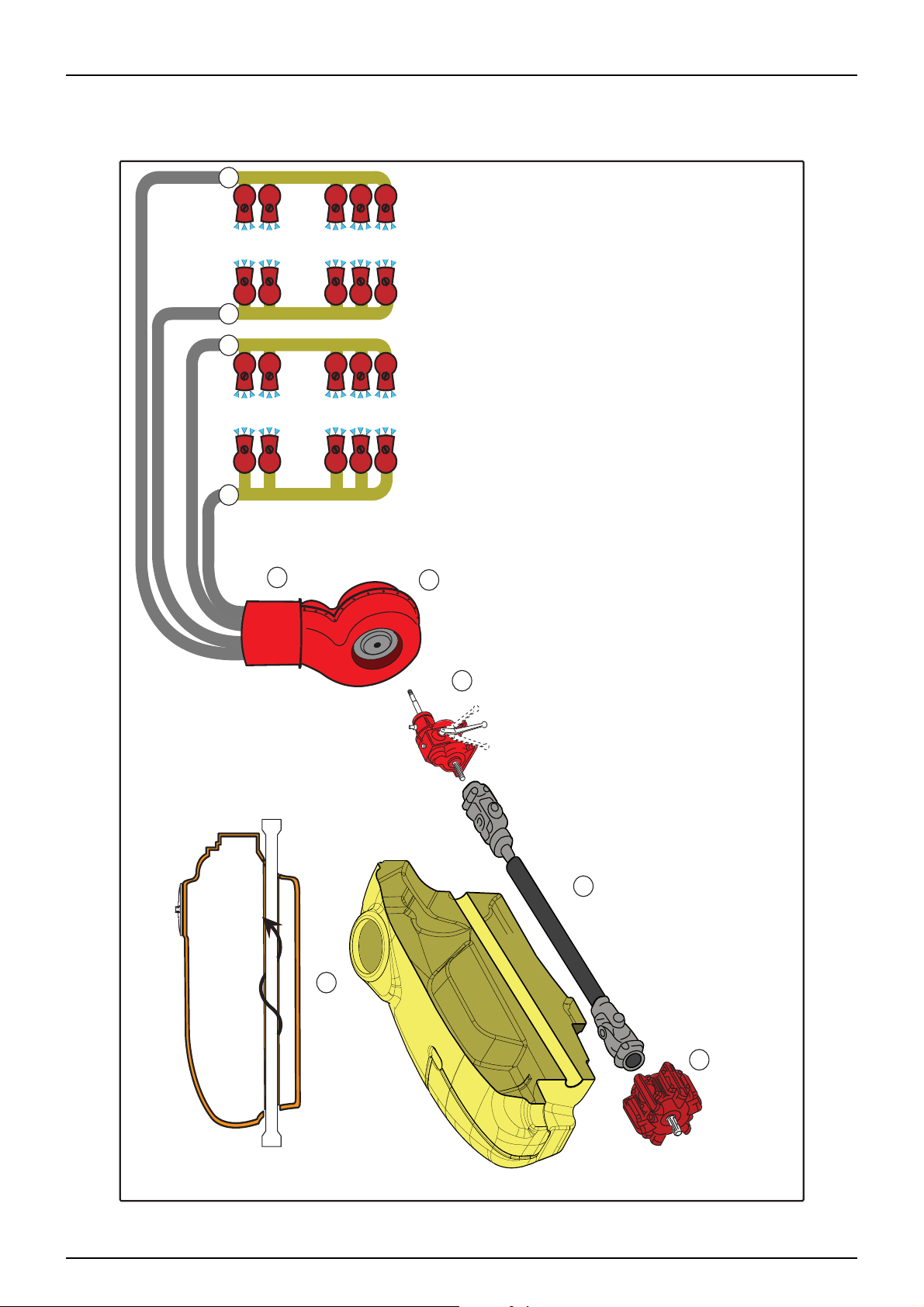
5 - Operation
Diagrams
Fluid System
OFF ON
15
15
18 19
17
16
Main Tank Supply - Suction
Fluid under pressure
External Fill Source
Rinse Tank Supply / External Fill
Bypass
Mercury Covamax Liquid System
Line
13 Distribution Valves (EVC or CB/2)
14 Pressure Filters
15 Boom Spray Zone Selector Valves
16 Left Boom Outer Nozzles
17 Left Boom Inner Nozzles
18 Right Boom Inner Nozzles
19 Right Boom Outer Nozzles
20 Pressure Agitation Line
4
5
20
21
1
21 Bypass Agitation Line
22 Pressure Relief Bypass
5. 10
14
14
13 13
12 11
9
10
Main Tank
1
2 Handwash
3 Handwash Tank Outlet
4 Powder Mixer (Option)
5 Agitators
6 Suction Filter
7 External Source
8 Main Pump
9 Manual Pressure Relief
10 Manifold
11 Pressure Regulator
12 Flow Meter (Option)
2
3
6
22
7
8
Page 65
Air Flow Delivery
5 - Operation
7 8 9 10
Product Pump
1
2 Drive Shaft
3 Main Tank
4 Gearbox
5 Blower Fan
6 Distribution Stack
7 Left Boom Outer Nozzles
6
5
8 Left Boom Inner Nozzles
9 Right Boom Inner Nozzles
10 Right Boom Outer Nozzles
Mercury Covamax Air Delivery System
4
2
3
1
5. 11
Page 66

5 - Operation
External Fill - Suction
1
Main Tank
5 Agitators
6 Suction Filter
7 External Source
8 Main Pump
9 Manual Pressure Relief
10 Manifold
11 Pressure Regulator
12 Flow Meter (Option)
13 Distribution Valves (EVC or CB/2)
21 Bypass Agitation Line
22 Pressure Relief Bypass Line
Main Tank Supply - Suction
Fluid under pressure
Rinse Tank Supply / External Fill
Bypass
7
External Fill Source
10
9
21
1
22
13 13
12 11
5
6
8
External Fill
Fluid can be drawn from an external source and pumped into the tank. For example, tank filling.
For external fill operation all manifold taps (10) must be ‘OFF’ and the suction filter handle (6) must be turned to
point towards the external source, this will allow the pump to draw liquid from the external source (7) under
suction, the liquid is then driven through the pump (8) and onto the manifolds, as no taps are open the fluid will
be bypassed to the main tank.
÷
Agitation may be left on during this procedure.
5. 12
Page 67

5 - Operation
Agitation
Agitation is controlled by turning the agitation handle on the manifold (10) to be inline with the fluid flow and the
handle on the suction filter (6) pointed towards the main tank (supply source).
When the pump is running, the fluid will be drawn from the main tank under suction to the pump. The pump will
pressurised the fluid and feed it to the manifold.
When the agitation handle is opened the fluid flows through line (20) and is ejected through the agitators in the
tank (5).
Agitation
Main Tank Supply - Suction
Fluid under pressure
Rinse Tank Supply / External Fill
Bypass
10
1
Powder Mixer
Mercury Covamax Agitation
Not Used
5
20
21
13 13
12 11
13 Distribution Valves (EVC or CB/2)
20 Pressure Agitation Line
21 Bypass Agitation Line
ief Bypass Line
22 Pressure Rel
9
22
10
8
6
Main Tank
1
5 Agitators
6 Suction Filter
7 External Source
8 Main Pump
9 Manual Pressure Relief
10 Manifold
11 Pressure Regulator
12 Flow Meter (Option)
5. 13
Page 68

5 - Operation
Mercury Covamax Powder Mix
1
Main Tank
4 Powder Mixer (Option)
6 Suction Filter
8 Main Pump
10 Manifold
Main Tank Supply - Suction
Fluid under pressure
Rinse Tank Supply / External Fill
Chemical Induction
Bypass
10
1
Agitation
Powder Mixer
Not Used
10
4
6
8
Powder Mixing Option
Powder mixing (optional) is carried out by;
• Turn suction filter handle (6) towards main tank
• Run pump (8)
• Open tap for powder mixer on manifold (10)
• Fluid will be pumped through the manifold and via chemical induction line to the mixer basket (4)
• Close tap when not in use
€
DANGER: Do not operate the powder mixing feature with the lid removed as chemical product may be
forced from the basket and cause chemical contamination to surrounding areas or contact with operator.
5. 14
Page 69

Spray Distribution
Spray Distribution
1
Main Tank
5 Agitators
6 Suction Filter
8 Main Pump
9 Manual Pressure Relief
10 Manifold
11 Pressure Regulator
12 Flow Meter (Option)
13 Distribution Valves (EVC or CB/2)
14 Pressure Filters
15 Boom Spray Zone Selector Valves
16 Left
Boom Outer Nozzles
17 Left Boom Inner Nozzles
18 Right Boom Inner Nozzles
19 Right Boom Outer Nozzles
21 Bypass Agitation Line
22 Pressure Relief Bypass Line
Main Tank Supply - Suction
Fluid under pressure
Rinse Tank Supply / External Fill
Bypass
OFF ON
External Fill Source
10
9
14
14
15
15
16
17
21
1
18 19
22
13 13
12 11
5
6
8
Spray distribution is carried out with the following considerations;
• Turn suction filter handle (6) towards main tank
• Turn ‘ON’ pump
• Set pressure regulation to desired spray pressure.
• Open required boom section valves (13)
• Fluid will pump through pressure filters (14)
• Open required boom zone valves (15)
• Open individual nozzle spouts valves as required.
Excess fluid will be bypassed back to the main tank via the bypass agitation line (21)
5 - Operation
5. 15
Page 70

5 - Operation
Pressure Regulation & Pressure Relief
1
Main Tank
5 Agitators
6 Suction Filter
8 Main Pump
9 Manual Pressure Relief
10 Manifold
11 Pressure Regulator
12 Flow Meter (Option)
13 Distribution Valves (EVC or CB/2)
14 Pressure Filters
15 Boom Spray Zone Selector Valves
21 Bypass
Agitation Line
22 Pressure Relief Bypass Line
Main Tank Supply - Suction
Fluid under pressure
Rinse Tank Supply / External Fill
Bypass
OFF
10
9
14
14
15
15
21
1
22
13 13
12 11
5
6
8
Pressure Regulation & Pressure Relief
If no valves on the manifold are open, the fluid will then cycle to the pressure relief and regulation manifold to
maintain system pressure as set at the pressure. The pressure relief valve will prevent over-pressurisation by
allowing excess fluid to bypass to the tank via the pressure relief valve (9) and the Pressure Relief Bypass line (22).
Pressure regulation is controlled by the pressure regulator (11) which allows electronic control of system pressure
and a bypass agitation line (21) from the rear of the regulator which diverts excess fluid back to the main tank
agitators.
5. 16
Page 71

6 - Maintenance
Introduction
This section of the manual deals with maintenance. It is vitally important that you prepare the service area and the
sprayer to minimise any potential risk to the operator or service technician. The following suggestions are made in
the interests of safe work practices.
Maintenance procedures involve:
• -Reading and interpreting technical information and illustrations
• -Lifting the sprayer’s axle off the ground
• -Cleaning of filters
• -Brake adjustments
• -Servicing hydraulic components
• -Testing and servicing of fluid systems
• -Lubrication
Before you get started...
Performing service and maintenance procedures safely requires awareness, preparation and common sense.
Below is a list of safety issues which must be observed before commencing service or maintenance procedures:
Before carrying out any service procedures observe the following:
• Clean and de-contaminate the sprayer and use chemical safety protection gear (see “Chemical Safety” section
2 and “Cleaning and De-contamination” section 5)
• Make sure your work area has lifting and safety equipment of a suitable load bearing capacity
• Always wear safety eye wear, overalls, safety boots and gloves where appropriate
• Keep animals and people away from the service area at all times unless involved in the procedure
• Keep children away
• Position the sprayer on a suitable flat surface with enough room for the boom to operate
• Never perform set-up, service or maintenance procedures with the engine running
• Turn the engine off, place in park with the hand bake on and remove the ignition key!
• Use wheel chocks in front and behind of each wheel when jacking sprayer
• Always use safety stands when lifting the sprayer off the ground
• Always re-fit all safety equipment and shields after service procedures
• Think each job through before commencing work and assess any potential risk
• Avoid working alone or at least have some-one check on you periodically
• Carry a mobile phone on you for emergencies
• Dis-connect the power and clear the area of any flammable material before using an arc welder
• If any procedure is unclear or requires facilities which are not available, refer the job to your HARDI dealer.
Spare parts
For spare parts diagrams, please visit the web site at www.agroparts.com and register for free, or contact your
HARDI dealer.
Note: Due to on-going development the parts information
÷
at www.agroparts.com may not currently contain all the
spare parts drawings specific to your product.
Please contact your HARDI dealer for further information and
updates.
1. 1
Page 72

6 - Maintenance
Lubrication
General info
Although the metal parts of the mistblower have received a strong protective surface treatment, it is
recommended to apply a film of anticorrosion oil (e.g. CASTROL RUSTILLO or SHELL ENSIS FLUID) to all metal parts
to prevent discolouration of the enamel by the chemical products; it will also make it easier to clean the
mistblower.
Note: The surface protectant treatment should be repeated every time the protective film is washed off.
÷
To avoid contamination from dirt and condensed water, always keep lubricants clean, dry and cool - preferably at
a constant temperature.
Keep oil filling jugs, hoppers and grease guns clean, and clean the lubricating points thoroughly before applying
lubricant.
Avoid skin contact with mineral oil products for long periods.
Always follow the directions concerning recommended quantity. If no recommended quantity is given, feed the
lubricator until new grease becomes visible.
Pictogram in lubrication & oiling plans indicate the following:
• Lubricant to be used
• Operating hours before next lubrication
Note: If the sprayer is cleaned with a high pressure cleaner full lubrication of the entire machine is
÷
recommended.
Lubrication Pictogram
The pictogram shown may be used to determine the lubricant
required for the job and the frequency that the task should be
carried out.
The example shown represents the following;
• B = lubricant type - (Molybdenum-Dysulphide Grease)
• 50 = task frequency - (50 hour intervals)
Recommended lubricants
BALL BEARINGS
Castrol EPL2 Grease or equivalent.
Castrol Molybdenum-disulphide grease
or equivalent
SLIDE BEARINGS
1. 2
OIL LUBE POINTS
Castrol EPX 80W/90 or equivalent
“O” RING SEALS
Castrol Non-mineral based Rubber
grease or equivalent
Page 73

Transmission Shaft (PTO) lubrication
A A BA B A A
B
B
The universal joints and bearings must be lubricated with grease.
At points (A) this should be done after every 10 working hours, and
the tubes and axles (B) every 20 hours.
6 - Maintenance
Drawbar lubrication
To avoid the wear and seizing up of the drawbar’s rotating parts
keep them greased at all times.
Both the ring drawbar and the wide angle drawbar have a grease
nipples on their upper surface.
On the underside of the drawbar there is a point that must also be
greased.
1. 3
Page 74

6 - Maintenance
B
5
A
100
B
50
Boom lubrication
The boom contains several points requiring lubrication as listed
below. It is recommended to lubricate these points regularly to
maintain boom efficiency.
• Fold Cylinder Pivots
• Tilt Cylinder Pivots
Axle lubrication
The hub is the part of the axle that must be greased. Remove hub cap and grease the inside of the rotating head.
In the case of your machine being fitted with the axle with hydraulic brake the moving part of the brake must also
be greased as shown by the arrow.
1. 4
Page 75

O-Ring and Filter lubrication
D
50
SIGHT GAUGE
DRAIN PLUG
FILL - 1 LITRE CAPACITY
250
SAE 20/50
REMOTE FILLING TUBE
Whenever dismantling any filter or hose pipe take care not to
pinch the o-rings fitted to them. When replacing the pipe fitting,
smear the o-ring with oil or grease so that it falls easily into place
in its groove.
Gearbox lubrication
The gearbox has a sight gauge that should be checked regularly
and the oil should be changed every 250 hours.
The gearbox contains 1 litre of SAE-20/50 multigrade oil
6 - Maintenance
• Item 1 - Sight Gauge
• Item 2 - Oil Fill
• Item 3 - Oil Drain Plug
To allow for easy access when filling the gearbox with oil, a remote
filling tube is fitted fron the fill point on top of the gearbox and
extends to the boom centre frame where it has a capped fitting in
an easily accessible area.
Pump Maintenance
On HARDI 363 pumps, grease the pump, every 50 working hours or
once a month, through the grease nipple situated on the end of
the input shaft. The grease goes along the grooves in the shaft to
reach the crankcase where it is distributed around bearings,
conrods, etc.
AR high pressure series pumps use wet sump lubrication. It is
recommended to check oil level before starting and change oil
after the first 50 hours of operation then regularly at 500 hour
intervals with SAE 30W oil. For servicing and troubleshooting
please refer to AR Pumps documentation or their website.
1. 5
Page 76

6 - Maintenance
4
4
3
1
5
2
6
Servicing
Servicing requirements for the MERCURY COVAMAX are;
• Hourly Interval Servicing, and
• Occasional Maintenance
10 Hour Servicing
The following items (if fitted) require servicing at 10 hour intervals;
• Suction Filter
• Pressure Filters
• Nozzle Filters
• Liquid System
• Boom Centre
Suction Filter- 10 hour intervals
To service the suction filter;
DANGER: Spray fluid contained in the system will gravity
€
feed from the suction filter when servicing. Extreme care
should be taken to avoid contact or contamination from
spray chemicals. Please refer to chemical manufacturers
safety advice when dealing with spray chemical.
Turn suction filter handle 90 degrees to shut-off the valve
÷
and isolate fluid flow from main tank
1. Loosen filter bowl nut (1) and remove bowl(2) and nut(1) from
main body(6).
Fluid in system will drain from suction filter when bowl is
÷
removed.
2. Remove seal(3), filter(5) and orings(4)
3. Clean filter
4. Clean and re-lubricate seals and O-rings
5. Refit items in reverse order
6. Tighten bowl nut (1) sufficiently to prevent leakage
1. 6
Page 77

6 - Maintenance
Inline Boom Filters- 10 hour intervals
DANGER: Spray fluid contained in the system will gravity feed from the filter when servicing. Extreme care
€
should be taken to avoid contact or contamination from spray chemicals. Please refer to chemical
manufacturers safety advice when dealing with spray chemical.
The boom may be equipped with optional In-Line Filters, when
fitted should be serviced at 10 hourly intervals.
Unscrew the filter bowl to inspect and clean the filter.
When reassembling the O-ring should be lubricated with rubber
grease.
Alternative filter meshes are available. See section on Technical
specifications - Filters and nozzles.
Liquid System- 10 hour intervals
Fill with clean water, operate all functions and check for leaks using higher spray pressure than normal. Check
nozzle spray patterns visually using clean water.
1. 7
Page 78

6 - Maintenance
50 Hour Servicing
The following items (if fitted) require servicing at 50 hour intervals;
• Transmission Shaft (P.T.O)
• Wheel Bolts & Nuts
• Tyre Pressures
• Boom
• Nozzle filters
Transmission Shaft- 50 hour intervals
Check function and condition of the transmission shaft protection guard. Replace possible damaged parts.
Wheel Bolts & Nuts- 50 hour intervals
Tighten wheel bolts and nuts as follows with following torque
wrench settings:
Wheel hub to rim plate: 330Nm (243 ft/lb)
Tightening sequence: See illustration and tighten in order of
numbering.
Tyre Pressures- 50 hour intervals
Check the tyre pressures every 50 hours. Only inflate to
recommended pressure of tyre manufacturer.
DANGER: Never inflate tyres to more than the pressure
€
specified. Over-inflated tyres can explode and cause severe
personal injuries!
Boom Adjustments - 50 hour intervals
Prior to making boom adjustments, make sure the following tasks have been carried out;
• Lubricate all parts of the sprayer
• Connect the sprayer to a tractor
• Place tractor and sprayer on level ground (horizontal surface)
• Unfold boom
Nozzle Filters- 50 hour intervals
Clean and inspect nozzles
1. 8
Page 79

6 - Maintenance
1
2
3
4
5
6
7
8
9
250 Hour Servicing
Readjustment of Boom- 250 hour intervals
The boom should be checked and adjusted every 250 hours or as necessary, details of adjusting procedures are
covered in the occasional maintenance section.
Hydraulic Circuit- 250 hour intervals
Check the hydraulic circuit for leaks and repair if necessary.
DANGER: Never use hands to check for hydraulic leaks, use a piece of cardboard or similar.
€
WARNING: Hoses for boom lift must be replaced every 5 years.
±
Hoses and Tubes- 250 hour intervals
Check all hoses and tubes for possible damage, pinching and proper attachment. Replace damaged hoses or tubes.
Wheel Bearings - 250 hour intervals
WARNING: If you do not feel totally confident changing wheel bearings, contact your HARDI® dealer’s
±
workshop.
Check for play in the wheel bearings:
• Place stop wedges in front of and behind LH wheel and jack
up RH wheel.
• Rock the RH wheel to discover possible play in the bearings.
• If any play is found, support the wheel axle to prevent the
trailer from moving.
• Remove hub cap (1) and cotter pin (9). Turn the wheel and
tighten the castle nut (2) until a slight resistance in the wheel
rotation is felt.
• Loosen the castle nut until the first notch - horizontal or
vertical - is aligned with the cotter pin hole in the shaft.
• Fit a new cotter pin (9) and bend it over the end of the axle.
• Fill the hub cap with fresh grease and screw it on to the hub
again.
Repeat the procedure on LH hub assembly.
Refit wheels and torque wheel nuts to 330Nm (243 ft.lb)
1. 9
Page 80

6 - Maintenance
1
2
3
4
5
6
7
8
9
1000 Hour Servicing
The following items (if fitted) require servicing at 1000 hour intervals;
• Wheel Bearings
• Transmission Shaft (P.T.O)
Wheel Bearings - 1000 hour intervals
Check the condition of the wheel bearings in the following way;
WARNING: If you do not feel totally confident changing wheel bearings, contact your HARDI® dealer’s
±
workshop.
• Place stop wedges in front of and behind LH wheel and jack
up RH wheel.
• Support the trailer with axle stands.
• Remove the wheel.
• Remove the hub cap (1), cotter pin (9) and castle nut (2).
• Remove outer bearing (3).
• Pull off the wheel hub assembly. Use a wheel puller if
necessary.
• Remove inner (6) bearing, seal (7) and backing ring (8).
• Clean all parts in degreasing detergent and dry them. Replace
if worn or damaged.
• Fill the hub and bearings with fresh grease.
• Assemble the hub and bearings using a new sealing ring (7).
• Fit castle nut. Rotate hub and tighten castle nut until a slight rotation resistance is felt.
• Loosen castle nut again until the first notch is aligned with the cotter pin hole in the shaft.
Attention: The shaft has a vertical and a horizontal cotter pin hole. Use the one first aligned with the notch when
μ
loosening the castle nut.
• Fit a new cotter pin and bend it.
• Fill the hub cap with fresh grease and carefully press it onto the hub.
• Replace the wheel and tighten the wheel nuts to 330Nm (243 ft.lb)).
• Tighten again after 10 hours of work.
• Check for bearing play every day until it has stabilized.
• Check wheel nuts daily
Transmission Shaft - 1000 hour intervals
Change the protection tube nylon bearings as described under “Shield replacement on transmission shaft”.
1. 10
Page 81

6 - Maintenance
Occasional Maintenance
The maintenance and replacement intervals for the following will depend very much on the conditions under
which the sprayer will be operated and are therefore impossible to specify.
The following items are subject to occasional maintenance and need to be check on a regular basis;
• Tyre Changing
• Pump Valves & Diaphragms replacement
• Pressure Cone Check / Replacement
• Flow Meter Inspection
• Pressure Regulator checks
• Section valve checks
• Drain valve seal replacement
• Drain valve cord replacement
• Off Season storage
Tyre Changing
Should it be necessary to replace tyres, HARDI recommended to
leave this task to a specialist tyre fitting company and follow the
mentioned rules.
• Never exceed the maximum mounting pressure molded on
the tyre!
• After mounting tyres adjust inflation pressure to operation
pressure recommended by the tyre manufacturer.
• Do not use tubes in tubeless tyres.
• Refit wheel to trailer and torque wheel nuts to 330Nm (243
ft.lb) in the sequence shown below
1. 11
Page 82
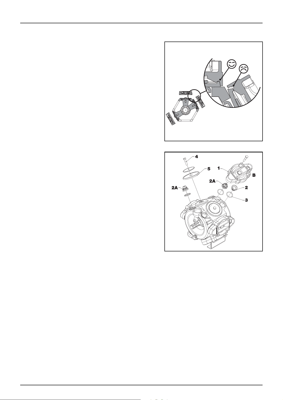
6 - Maintenance
Pump Valves & Diaphragms Replacement
363 Pumps
Attention: Before removal of components, take note of correct
μ
orientation so that they may be replaced correctly when
reassembling.
Note: It is recommended to apply a light amount of rubber
÷
grease to all rubber seals.
Note: Check the drain hole at base of pump for blockages
÷
Note: If fluids have reached the crankcase (ie. if the
÷
diaphragm has ruptured) re-grease the pump thoroughly.
Note: Make sure that diaphragms are properly seated when
÷
reassembling. Poor sealing will lead to worn components
and frequent pump repair.
Val ve s
• Remove valve cover (1)
• Remove valve (2A & 2)
• Replace O-rings (3)
• Reinstall components and torque Valve Cover to 45 ft/lb (60
Nm)
Diaphragms
• Remove the diaphragm bolt (4)
• Change the diaphragm (5)
• Reinstall components and torque;
• Diaphragm Bolt to 45 ft/lb (60 Nm),
• Diaphragm Cover to 50 ft/lb (70Nm)
363 Pump
Attention: A special valve with white flap (2A) is used at the two upperside inlets. It has to be placed in the valve
μ
openings as shown. All others are the type with black flap. It is recommended to use new gaskets (3) when changing
or checking the valves.
Note: It is recommended to apply a light amount of rubber grease to all seals.
÷
Flow Meter Inspection
An inspection of the paddle wheel inside the flowmeter should be carried out every year to check for wear or if you
suspect the flowmeter to be faulty.
Checks to verify functionality of the flowmeter are detailed in the fault finding section of this manual.
1. 12
Page 83

6 - Maintenance
PRESSURE REGULATOR
A
Check for EVC Pressure Regulator
DANGER: Make sure tank has been thoroughly emptied and decontaminated before commencing any work
€
on the fluid system.
Periodically check the EVC pressure regulation valve for proper sealing. If it becomes difficult to build up sufficient
pr ess ure or i f pr ess ure flu ctua tio ns o ccu r, it may b e ne cessary to replace piston and cylinder. Do this by running the
sprayer with clean water and open all distribution valves using the following steps;
• Wind pressure controller up to maximum.
• Cautiously remove the u-clip and pull out the hose for the
return line port (A).
• When the housing is drained, there should be no liquid flow
through the return line port (A).
• Run pump with Distribution valves open
• Measure the leakage rate out of port (A), If the rate is greater
than 5 litres per minute the valve cylinder (C), piston (F) and
o-ring (D) must be changed.
• Remove the screws and lift the motor housing off the valve
housing.
• Undo the nut (E) and replace the valve cylinder (C), piston (F)
and o-ring (D).
• Reassemble in reverse order.
Cone Check for Distribution valves
DANGER: Make sure tank has been thoroughly emptied and decontaminated before commencing any work
€
on the fluid system.
Periodically check the distribution valves for proper sealing. Do this by running the sprayer with clean water and
open all distribution valves. Cautiously remove the clip (A) and pull out the hose (B) for the return line. When the
housing is drained, there should be no liquid flow through the return line. If there is any leakage, the valve seal (E)
must be changed on all motor assemblies. Remove the clip (C) and lift the motor housing off the valve housing.
Then unscrew the screw (D) and replace the valve seal (E). Reassemble in reverse order. Service kits are available
through your local HARDI dealer.
1. 13
Page 84

6 - Maintenance
Drain Valve Seal Replacement
If the main tank drain valve leaks, the seal and seat can be changed
the following way.
• Remove U-Clip (A) and remove Drain Valve (B)
• Disassemble drain valve and replace items (C,D,E&F)
• Reassemble in reverse order
DANGER: Make sure tank has been thoroughly emptied and
€
decontaminated before commencing any work on the fluid
system.
DANGER: Do not enter the inside of the tank - the parts can
€
be changed from the outside of the tank!
WARNING: Use eye / face protection mask when dismantling
±
the tank drain valve!
Attention: Check function of valve with clean water before filling chemicals into the tank
μ
Drain Valve Cord Replacement
If the main tank drain valve cord is damaged or broken, the cord can be replaced the following way.
• Remove U-Clip and remove Drain Valve
• Remove old cord and handle
• Attach new cord to handle
• Working from the top of the tank - feed the new cord through the locking guide and down through the drain
valve outlet
• Reattach cord to drain valve and refit the drain valve into the outlet
• Gently pull drain valve handle to take up excess cord length
• Determine correct position for handle and readjust cord fixing at handle to obtain desired cord length.
DANGER: Make sure tank has been thoroughly emptied and decontaminated before commencing any work
€
on the fluid system.
DANGER: Do not enter the inside of the tank - the parts can be changed from the outside of the tank!
€
WARNING: Use eye / face protection mask when removing the tank drain valve!
±
Attention: Check function of valve with clean water before filling chemicals into the tank
μ
1. 14
Page 85

6 - Maintenance
Off Season Maintenance
Off season storage program
When the spraying season is over, you should devote some extra time to the sprayer. If chemical residue is left over
in the sprayer for longer periods, it will reduce the life of the individual components. To preserve the sprayer intact
and to protect the components, carry out following off-season storage program.
• Clean the sprayer completely - inside and outside - as described under “Cleaning of the sprayer”. Make sure
that all valves, hoses and auxiliary equipment have been decontaminated and flushed with clean water
afterwards, so no chemical residue is left in the sprayer.
• Replace possible damaged seals and repair possible leaks.
• Empty the sprayer completely and let the pump work for a few minutes. Operate all valves and handles to
drain as much water off the spraying circuit as possible. Let the pump run until air is coming out of all nozzles.
Remember to drain the hand wash tank also.
• If stored in cold climate areas, pour approx. 50 litres of anti-freeze mixture consisting of 1/3 automotive antifreeze and 2/3 water into the tank.
• Engage the pump and operate all valves and functions on the MANIFOLD, operating unit, chemical inductor
etc. allowing the anti-freeze mixture to be distributed around the entire circuit. Open the operating unit main
on/off valve and distribution valves so the anti-freeze is sprayed through the nozzles as well. The anti-freeze
will also prevent O-rings, seals, diaphragms etc. from drying out.
• Lubricate all lubricating points according to the lubricating scheme - regardless of intervals stated.
• When the sprayer is dry, remove rust from possible scratches or damages in the paint and touch up the paint.
• Remove the glycerine-filled pressure gauges and store them frost free in vertical position.
• Apply a thin layer of anti-corrosion oil (e.g. SHELL ENSIS FLUID, CASTROL RUSTILLO or similar) on all metal
parts. Avoid oil on rubber parts, hoses and tyres.
• Fold the boom in transport position and relieve pressure from all hydraulic functions.
• All electric plugs and sockets are to be stored in a dry plastic bag to protect them against damp, dirt and
corrosion.
• Remove the control boxes and computer display from the tractor, and store them dry and clean (in-house).
• Wipe hydraulic snap-couplers clean and fit the dust caps.
• Apply grease on all hydraulic ram piston rods which are not fully retracted in the barrel to protect against
corrosion.
• Chock up the wheels, to prevent moisture damage and deformation of the tyres. Tyre blacking can be applied
to the tyre walls to preserve the rubber.
• To protect against dust the sprayer can be covered by a tarpaulin. Ensure ventilation to prevent condensation.
Preparing the sprayer for use after storage
After a storage period the sprayer should be prepared for the next season the following way:
• Remove the cover.
• Remove the support from the wheel axle and adjust the tyre pressure.
• Wipe off the grease from hydraulic ram piston rods.
• Fit the pressure gauges again. Seal with Teflon tape.
• Connect the sprayer to the tractor including hydraulics and electric’s.
• Check all hydraulic and electric functions.
• If treated with anti-freeze when storing, empty the tank of any remaining anti-freeze.
• Rinse the entire liquid circuit on the sprayer with clean water.
• Fill with clean water and check all functions.
1. 15
Page 86

6 - Maintenance
Maintenance Schedule
Review the following maintenance schedule regularly to determine when maintenance is required. This
maintenance schedule is a guide only and can be increased in frequency if desired.
Consult the maintenance section of this manual for proper maintenance procedures.
Service to be Performed Interval
X - REQUIRED SERVICE INTERVAL
10 HRS
50 HRS
250 HRS
1 YEAR
As Required
Check wheel nut security X
Check tyre inflation X
Check gearbox oil level X
Check product pump oil - AR Pumps X
Lubricate drive shaft lock pins X
Lubricate drawbar grease nipples X
Check hydraulic oil level (Tractor) X
Check hydraulic lines and fittings for leaks X
Inspect fluid system for leaks X
Clean suction filter X
Clean pressure filters X
Lubricate drive shaft joints X X
Lubricate boom grease nipples X X
Lubricate boom pivots X X
Retorque wheel nuts to 330Nm (243 ft.lb) X
Lubricate wheel bearing caps X
Lubricate product pump input shaft grease nipple - HARDI 363 X
Adjust boom X
Check and Clean spray nozzle filters X
Check bearing play in wheel hubs X
Change gearbox oil X
Change product pump oil - AR Pumps X
Retorque wheel nuts to 330Nm (243 ft.lb) X
Check hydraulic lines and fittings for leaks X
Inspect fluid system for leaks X
Clean and re-lubricate boom grease nipples X
Clean and re-lubricate boom pivots X
Clean and repack wheel bearing assemblies X
Check blower fan bearing end play X
Clean and re-lubricate drive shaft joints X
Clean and re-lubricate drawbar grease nipples X
Change gearbox oil X
Change product pump oil - AR Pumps X
Lubricate product pump input shaft grease nipple - HARDI 363 X
Replace pump valves and diaphragms X
Check and Adjust EVC pressure regulator X
Check cone for section distribution valves X
Replace drain valve seal X
1. 16
Page 87

6 - Maintenance
Record maintenance activities on the following pages whenever it is performed. This will help to record the
servicing history of your trailer for future reference.
Maintenance Activity Record
Date Service Performed
1. 17
Page 88

6 - Maintenance
Maintenance Activity Record
Date Service Performed
1. 18
Page 89

7 - Fault Finding
Operational Problems
Introduction
In most cases where faults are experienced the most commonly accepted diagnostic approach is to rule out
possible causes systematically by a process of elimination. As a rule this process can begin by investigating the
following factors which have previously been found responsible:
• Minor leaks on the suction side of the pump will reduce the pump capacity or stop the suction completely.
• Pressure filters becoming blocked will result in rising pressure at the pressure gauge but falling pressure at
the nozzles.
• Foreign material which has found it’s way to the pump valves will reduce pump efficiency.
• Poorly re-assembled pumps, will allow the pump to suck air resulting in reduced or no fluid capacity
(investigate this if the pump was recently overhauled / serviced).
• Contamination of the hydraulic system will result in rapid wear to hydraulic components.
It is good practice to start by checking these basics:
• Filling, pressure and nozzle filters are clean.
• Check hoses for leaks and cracks, paying particular attention to suction hoses.
• Check gaskets and O-ring seals are present and in good condition.
• Check that the pressure gauge is in good working order (accurate calibration and chemical dosage depends
on it).
• Check the operating unit functions properly (always use clean water for testing)
• Flow meter is functioning correctly (further information is given later in this section).
Prevention
Naturally prevention is the best policy. Regular maintenance protects your investment, maximises sprayer
efficiency, minimises expensive down time and risk of personal injury.
To achieve the best possible service from your HARDI sprayer always make sure that:
• Hydraulic system components are maintained and kept clean (keep hose couplings up out of the dirt and
covered when not in use to prevent moisture contamination).
• Proper cleaning and de-contamination is carried out after each spray job and before changing chemicals or
crops. Never put off cleaning until later (crop protection chemicals are much harder to remove once they’ve
dried out).
• Regular and thorough maintenance is carried out on time (see maintenance section of this manual for
schedule).
1. 1
Page 90

7 - Fault Finding
Hydraulic system
Fau lt
Possible cause Suggested action
No boom movements when activated. Insufficient hydraulic pressure. Check oil pressure - min. 130 bar, max. 160 bar.
Insufficient oil supply. Oil flow must be min. 1 0 l/min. and max. 90 l/min.
Poor / corroded electrical connections. Check and clean connections, multi pin
Insufficient power supply. Voltage on activated solenoid valve must be more
Defective relay / diodes in junction box. Check relays, diodes and soldering at PCB in
Individual ram does not move. Blocked restrictor. Dismantle and clean restrictor.
Fluid system
Fau lt
No spray from boom when turned on. Air leak on suction line. Check if suction filter O-ring is sealing.
Possible cause Suggested action
Air in system. Fill suction hose with water for initial prime.
Suction/pressure filters blocked. Clean filters.
Check hydraulic oil level.
Check hydraulic oil level.
connections etc.
than 8 Volts. Use wires of at least 4 mm for power
supply.
junction box.
Check suction tube and fittings.
Check tightness of pump diaphragm and valve
covers.
Suction hoses or fittings blocked. Check fluid pick up in the tank is free of
obstruction/sedimentation etc.
Lack of pressure. Incorrect pump assembly. Check product pump
Blocked filter Check and clean filter
Pressure dropping. Filters becoming blocked Clean all filters. Fill with cleaner water. If using
powders, make sure agitation is on.
Nozzles worn. Check flow rate and replace nozzles if it exceeds
10%
Sucking air towards end of tank load. reduce or turn off agitation
Vacuum building in main tank. Check that the vent to atmosphere at the top of
the main tank is clear of obstruction.
1. 2
Page 91

7 - Fault Finding
Fluid system
Fau lt
Pressure increasing. Boom nozzle filters becoming blocked Clean all filters.
Formation of foam. Air is being sucked into system. Check tightness/gaskets/O-rings of all fittings on
Possible cause Suggested action
suction side.
Excessive liquid agitation. Reduce agitation
Liquid leaks from the bottom of HARDI pump. Damaged diaphragm Replace. See “Maintenance” section of this
Operating unit not functioning. Blown fuse(s). Check mechanical function of micro-switches. Use
Wrong polarity. Brown - pos. (+). Blue - neg. (-).
Section valves not closing properly. Check valve seals for obstruction and wear,
No power. Wrong polarity. Check that brown is pos. (+), Blue
Make sure that returns inside tank are present.
Use foam damping additive.
manual for instructions on servicing pumps
cleaning/lubricating agent if the switch does not
operate freely.
Check motor. 450-500 milli-Amperes max. Change
motor, if over.
overhaul if necessary (see “Maintenance” section
of this manual for details). Check micro-switch
plate position. Loosen screws holding plate a 1/2
turn. Check that the micro-switches in the EFC
valve motors are shutting the motors off correctly
is neg. (-).
Check printed circuit board for dry solders or
loose connections.
Check fuses and holders for integrity and security.
Sensors
Flow Sensor Inspection
The flow sensor is a “Proximity” type sensor and may be tested for
correct operation as follows:
• Switch on the power to the sprayer but do not run the pump
(ie 0 bar).
• Locate the Flow sensor in the fluid supply manifold at the
front of the sprayer and loosen it’s threaded retaining nut.
• Rotate the spindle by hand (do not use compressed air) and
watch the in-built LED test light for a signal.
If the sensor is working correctly the red LED will pulse with each
revolution of the spindle. If the Flow sensor is found to be
functional, re-install it in the manifold taking care not to damage
the “O” ring seal (use rubber grease on re-assembly).
1. 3
Page 92

7 - Fault Finding
1. 4
Page 93

Weights and Measures
WEIGHT
2300L
SIZE
WEIGHT
3300L
SIZE
8 - Technical Specifications
CONDITION MEASURE
Weight on Drawbar - Empty 56Kg
Weight on Drawbar - Full 545Kg
Weight on Wheels - Empty 1320Kg
Weight on Wheels - Full 3350Kg
Weight Total - Empty 1376Kg
Weight Total Full 3875Kg
Overall Length 4.6m
Max height - during transport 3.8m
Max height - boom fully lifted 4.1m
Max width - Folded 2.6m
Max width - Unfolded 7.0m
CONDITION MEASURE
Weight on Drawbar - Empty 56Kg
Weight on Drawbar - Full 680Kg
Weight on Wheels - Empty 1520Kg
Weight on Wheels - Full 4195Kg
Weight Total - Empty 1576Kg
Weight Total Full 4875Kg
Overall Length 4.9m
Max height - during transport 3.8m
Max height - boom fully lifted 4.1m
Max width - Folded 2.6m
Max width - Unfolded 7.0m
CONDITION MEASURE
Weight on Drawbar - Empty 56Kg
Weight on Drawbar - Full 950Kg
Weight on Wheels - Empty 1520Kg
Weight on Wheels - Full 4625Kg
WEIGHT
3800L
Max height - during transport 3.8m
Max height - boom fully lifted 4.1m
SIZE
Note: Measurements provided are approximate and may vary due to production processes, optional extras
÷
fitted and tank contents used. Tank capacities can vary in production due to shrinkage rates of materials
used and climatic variations at the time of production. Measurements provided are based on water with a
specific gravity of 1. Measurements are taken on a base model sprayer.
Weight Total - Empty 1576Kg
Weight Total Full 5575Kg
Overall Length 4.9m
Max width - Folded 2.6m
Max width - Unfolded 7.0m
8. 1
Page 94

8 - Technical Specifications
Recommended Tyre Sizes, Pressure & Load Ratings
Tank
Capacity
2300 L
3300 L
3800 L
3800 L
Note: Always refer to tyre manufacturer specifications when inflating tyres. Do not exceed recommended
÷
tyre pressure.
12.5/80 x 15.3 (14 ply) 3350Kg
12.5/80 x 15.3 (14 ply) 4195Kg
400/60 x 15.5 (14 ply) 4625Kg
400/55 x 22.5 (Flotation
Tyres) (14 ply) - optional
TYRE SIZE
Load with Full
Tank
4625Kg
Load Per
Tyre
1675Kg 30 Km/h 33PSi
2097Kg 30 Km/h 46 PSi
2312Kg 30 Km/h 44 PSi
4000Kg 30 Km/h 36 PSi
Max Speed
Max
Pressure
(PSI)
Conversion factors: Metric to Imperial units
As a general rule metric units of measure are used in this manual, however the following conversion table is
provided for the occasions where imperial measures occur.
Metric Imperial unit Factor
Weight kg lb x 2.205
Surface area ha acres x 2.471
cm in x 0.394
m ft x 3.281
Length
m yd x 1.094
km mile x 0.621
km/h mile/h x 0.621
Velocity
km/h m/s x 0.277
Quantities/
Area
Volume
Pressure bar lb./inv (p.s.i.) x 14.504
Temperature °C °F (°C x 1.8) + 32
Power kW hp x 1.341
l/ha gal/acre x 0.089
ml fl. oz x 0.0352
l Imp. pt. x 0.568
l gal x 0.22
Torque Nm lb.ft. x 0.74
Filter mesh specifications
Filter gauge
30 mesh: 0.58 mm - GREEN
8. 2
Page 95

50 mesh: 0.30 mm - BLUE
80 mesh: 0.18 mm - RED
100 mesh: 0.15 mm – YELLOW
8 - Technical Specifications
8. 3
Page 96

8 - Technical Specifications
Tightening Hydraulic Fittings
DANGER: Escaping fluid under pressure can penetrate the skin causing serious injury. Relieve pressure
€
before disconnecting hydraulic or other lines. Tighten all connections before applying pressure. Keep hands
and body away from pin holes and nozzles which eject fluids under high pressure. Use a piece of cardboard
or paper to search for leaks. DO NOT use your hand.
Tightening O-Ring Fittings
* Torque values shown are based on lubricated
÷
connections as in reassembly
• Inspect O-ring and seat for dirt or obvious defects.
• On angle fittings, back the locknut off until
washer bottoms out at top of groove.
• Hand tighten fitting until backup washer or
washer face (if straight fitting) bottoms on face
and O-ring is seated.
• Position angle fittings by unscrewing no more
than one turn.
• Tighten straight fittings to torque shown.
Tightening Flare Type Fittings
Threa
d Size
Nut
Size
across
flats
Torque Value *
Turns to
Tighten (After
Finger
Tightening)
(In.) (In.) (Nm) (lb-ft) (Flats) (Turns)
3/8 1/2 8 6 2 1/3
7/16 9/16 12 9 2 1/3
1/2 5/8 16 12 2 1/3
9/16 11/16 24 18 2 1/3
3/4 7/8 46 34 2 1/3
7/8 1 62 46 1-1/2 1/4
1-1/16 1-1/4 102 75 1 1/6
1-3/16 1-3/8 122 90 1 1/6
1-5/16 1-1/2 142 105 3/4 1/8
1-5/8 1-7/8 190 140 3/4 1/8
1-7/8 2-1/8 217 160 1/2 1/12
* Torque values shown are based on lubricated
÷
connections as in reassembly
• Check flare and flare seat for defects that might
cause leakage.
• Align hose end with fitting before tightening.
• Lubricate connection and hand tighten swivel nut
until snug.
• To prevent twisting the hose, use two wrenches.
Place one wrench on the hose end body and with
the second wrench, tighten the swivel nut to the
torque shown in this chart.
Threa
d Size
Nut
Size
across
flats
Torque Value *
Turns to
Tighten (After
Finger
Tightening)
(In.) (In.) (Nm) (lb-ft) (Flats) (Turns)
3/16 7/16 8 6 1 1/6
1/4 9/16 12 9 1 1/6
5/16 5/8 16 12 1 1/6
3/8 11/16 24 18 1 1/6
1/2 7/8 46 34 1 1/6
5/8 1 62 46 1 1/6
3/4 1-1/4 102 75 3/4 1/8
7/8 1-3/8 122 90 3/4 1/8
8. 4
Page 97

8 - Technical Specifications
Torque Specifications
Note: Use these torque values when tightening hardware (excluding: locknuts and self tapping, thread
÷
forming and sheet metal screws) unless specified otherwise. All torque values are in lb-ft except those
marked with an (*) which are lb-in (for metric torque value Nm, multiply lb-ft value by 1.355 or for lb-in
multiply by 0.113).
Unified
National
Thread
Dry Lubed Dry Lubed Dry Lubed
8-32 19* 14* 30* 22* 41* 31*
8-36 20* 15* 31* 23* 43* 32*
10-24 27* 21* 43* 32* 60* 45*
10-32 31* 23* 49* 36* 68* 51*
1/4-20 66* 50* 9 75* 12 9
1/4-28 76* 56* 10 86* 14 10
Grade 2 Grade 5 Grade 8
5/16-18 11 9 17 13 25 18
5/16-24 12 9 19 14 25 20
3/8-16 20 15 30 23 45 35
3/8-24 23 17 35 25 50 35
7/16-14 32 24 50 35 70 55
7/16-20 36 27 55 40 80 60
1/2-13 50 35 75 55 110 80
1/2-20 55 40 90 65 120 90
9/16-12 70 55 110 80 150 110
9/16-18 80 60 120 90 170 130
5/8-11 100 78 150 110 220 170
5/8-18 110 85 180 130 240 180
3/4-10 175 130 260 200 380 280
3/4-16 200 150 300 220 420 320
7/8-9 170 125 430 320 600 460
7/8-14 180 140 470 360 660 500
1-8 250 190 640 480 900 680
1-14 270 210 710 530 1000 740
Metric Coarse Grade 8.8 Grade 10.9 Grade 12.9
Thread Dry Lubed Dry Lubed Dry Lubed
M6 x 1.0 8 6 11 8 13.5 10
M8 x 1.25 19 14 27 20 32.5 24
M10 x 1.5 37.5 28 53 39 64 47
M12 x 1.75 65 48 91.5 67.5 111.5 82
M14 x 2.0 103.5 76.5 145.5 108 176.5 131
M16 x 2.0 158.5 117.5 223.5 165.5 271 200
8. 5
Page 98

8 - Technical Specifications
Pump Capacities
Hardi 363 pump
bar Litres per minute Kilowatts
01401.6
21361.8
41332.1
61302.5
10 127 3.4
363/7 @ 540 RPM
AR Pumps - BHS200
15 124 4.4
20 122 5.4
bar Litres per minute Horsepower
50 193.7 21.8
BHS200 @ 550 RPM
Spare part information
HARDI spare parts pages
For Spare Parts requirements, either contact your HARDI dealer, log onto www.agroparts.com (register for free and
click on the HARDI International Spare parts and service link) or visit our web site at: www.hardi.com.au
We apologise for any inconvenience.
Materials and recycling
Disposal of the sprayer
When the equipment has completed its working life, it must be thoroughly cleaned and de-contaminated before
disposal. The tank, hoses and synthetic fittings can be incinerated at an authorised disposal depot. The metallic
parts can be scrapped. Contact your local Authorities for information regarding safe disposal of the following
materials:
• Tank: HDPE
• Hoses: PVC
• Valves: mainly glass-filled PA.
• Fittings: PA
8. 6
Page 99

8 - Technical Specifications
Further information
HARDI spare part and technical support
HARDI Australia continues to invest heavily in research and development of sprayer technology to bring the best
and most innovative spray products to the Australian market.
In addition our spare parts and field support staff are working closely with our regional dealer network to provide
you the best after sales service and technical advice available.
Further information about spraying, our organisation and it’s product range is available through your HARDI
dealer or visit our web site at: www.hardi.com.au
8. 7
Page 100

8 - Technical Specifications
8. 8
 Loading...