

Hardi Mercury, Zaturn 2000 DUO T/AG820, Zaturn Plus 3000, Mercury 4000 SF85, Zaturn Instruction Book
...Page 1
Mercury
Zaturn
Instruction book
67029104-100 - Version 1.00
GB - 10.2016
www.hardi.com.au
Page 2

We congratulate you for choosing a HARDI plant protection product. The reliability and efficiency of this product depend upon your care. The first step is to carefully read and pay
attention to this instruction book. It contains essential information for the efficient use and
long life of this quality product.
The original instruction book is approved and published in English. All other languages are translations of the
original book. In the event of any conflicts, inaccuracies or deviations between the English book and other
languages, the English version shall prevail.
Illustrations, technical information and data in this book are believed to be correct at the time of printing. As it is
the policy of HARDI AUSTRALIA to continuously improve our products, we reserve the right to make changes in
design, features, accessories, specifications and maintenance instructions at any time and without notice.
HARDI AUSTRALIA is without any obligation in relation to implements purchased before or after such changes.
HARDI AUSTRALIA cannot undertake any responsibility for possible omissions or inaccuracies in this publication,
although everything possible has been done to make it complete and correct.
As this instruction book covers more models and features or equipment, which are available in certain countries
only, please pay attention to paragraphs dealing with precisely your model.
Published and printed by HARDI AUSTRALIA.
Page 3

Table of Contents
2 - General Safety Instructions
Obligations and Liability .......................................................................................................................7
Comply with the Instruction Book .............................................................................................................................................................. 7
Before First Use of the Sprayer ....................................................................................................................................................................... 7
Restricted Use ........................................................................................................................................................................................................... 8
Obligations of the Operator ............................................................................................................................................................................ 8
Risks in Handling the Sprayer ......................................................................................................................................................................... 9
Disclaimer ................................................................................................................................................................................................................... 9
Organizational Measures ....................................................................................................................10
Personal Protective Equipment ................................................................................................................................................................. 10
Representation of Safety Symbols ......................................................................................................11
Explanation of Symbols ................................................................................................................................................................................... 11
Warning Signs On The Sprayer ............................................................................................................12
Explanation of Labels ........................................................................................................................................................................................ 12
Safety and Protection Equipment .......................................................................................................14
Safety at Start-up ................................................................................................................................................................................................. 14
Faulty Safety Equipment ................................................................................................................................................................................ 14
Informal Safety Measures ....................................................................................................................15
Additional Safety Instructions ..................................................................................................................................................................... 15
Operator Training ................................................................................................................................16
Authorized Persons ............................................................................................................................................................................................ 16
Safety Measures in Normal Operation ................................................................................................17
Protection Equipment ..................................................................................................................................................................................... 17
Residual Energy ...................................................................................................................................18
Possible Dangers ................................................................................................................................................................................................. 18
Service and Maintenance Work ...........................................................................................................19
Statutory Inspection .......................................................................................................................................................................................... 19
Preventive Measures ......................................................................................................................................................................................... 19
Design Changes ...................................................................................................................................20
Operator Limitations ......................................................................................................................................................................................... 20
Spare Parts, Wear Parts and Aids ............................................................................................................................................................... 20
Cleaning and Disposal .........................................................................................................................21
Environmental Protection ............................................................................................................................................................................. 21
Workstation .........................................................................................................................................22
Intended Place for Operator ........................................................................................................................................................................ 22
Risks of Non-Compliance ............................................................................................................................................................................... 22
If the Safety Information is Ignored ....................................................................................................23
Possible Risks and Dangers ........................................................................................................................................................................... 23
Safety Information For Operators .......................................................................................................24
General Safety and Accident Prevention ............................................................................................................................................. 24
Coupling and Uncoupling the Sprayer ................................................................................................................................................. 24
Use of The Sprayer .............................................................................................................................................................................................. 25
Road Transport ..................................................................................................................................................................................................... 26
Hydraulic System ................................................................................................................................................................................................. 27
Electrical System .................................................................................................................................................................................................. 28
Field Sprayer Operation .................................................................................................................................................................................. 29
Environmental Precautions .......................................................................................................................................................................... 29
Service Work Precautions ............................................................................................................................................................................... 30
Cleaning .................................................................................................................................................................................................................... 30
3 - Description
General info .........................................................................................................................................31
View ............................................................................................................................................................................................................................. 31
Use of the mist blower .................................................................................................................................................................................... 33
Roadworthiness ................................................................................................................................................................................................... 33
Identification plate ............................................................................................................................................................................................. 33
Chassis ........................................................................................................................................................................................................................ 33
Tank ............................................................................................................................................................................................................................. 34
3
Page 4

Liquid system ......................................................................................................................................35
General information .......................................................................................................................................................................................... 35
The liquid circuit .................................................................................................................................................................................................. 35
Diaphragm pump ............................................................................................................................................................................................... 35
Valves .......................................................................................................................................................................................................................... 35
Valves and symbols ............................................................................................................................................................................................ 35
Manifold system (Zaturn only) .................................................................................................................................................................... 36
Agitation / Tank rinse valve (Zaturn only) ............................................................................................................................................ 36
Pressure valve (Zaturn only) ......................................................................................................................................................................... 36
Suction valve (Zaturn only) ........................................................................................................................................................................... 36
Agitator (Zaturn) .................................................................................................................................................................................................. 37
Agitator (Mercury) .............................................................................................................................................................................................. 37
Rate Controller DB3610 .......................................................................................................................38
Axial blower units ................................................................................................................................39
Technical information ...................................................................................................................................................................................... 39
AG820 and SF65 ................................................................................................................................................................................................... 39
Air flow of axial blower Zaturn .................................................................................................................................................................... 40
Deflectors ................................................................................................................................................................................................................. 41
Specific for SF fans .............................................................................................................................................................................................. 42
Powder mixer ........................................................................................................................................................................................................ 43
Centrifugal Blower Units (Turbines) ....................................................................................................44
General information .......................................................................................................................................................................................... 44
Air flow of HF640D centrifugal turbines ............................................................................................................................................... 45
Protective grid ....................................................................................................................................................................................................... 45
Gearbox .................................................................................................................................................................................................................... 46
HF 640D Turbines ............................................................................................................................................................................................... 46
Clutch (All blower types) ................................................................................................................................................................................ 46
Equipment ...........................................................................................................................................47
Ring drawbar .......................................................................................................................................................................................................... 47
Turnable drawbar ................................................................................................................................................................................................ 47
Wedges ..................................................................................................................................................................................................................... 47
Boom ...................................................................................................................................................48
Breakaway Arms ................................................................................................................................................................................................... 48
4 - Sprayer setup
Connecting the articulated drawbar ...................................................................................................................................................... 50
Lock device on turnable drawbar ............................................................................................................................................................. 51
Hydraulic connections .........................................................................................................................53
General information .......................................................................................................................................................................................... 53
Electrical connections ..........................................................................................................................54
General information .......................................................................................................................................................................................... 54
Operating unit ...................................................................................................................................................................................................... 54
Rate controller .....................................................................................................................................55
Rate controller DB 3610 .................................................................................................................................................................................. 55
Fluid circuit ..........................................................................................................................................56
Deflectors ................................................................................................................................................................................................................. 57
V deflector ............................................................................................................................................................................................................... 57
Top S or L ................................................................................................................................................................................................................. 57
Adjustable bottom deflector ....................................................................................................................................................................... 58
DUO T and V deflector ..................................................................................................................................................................................... 59
Boom Adjustments ..............................................................................................................................60
Boom Width - Row Spacing ......................................................................................................................................................................... 60
Crop Height Adjust ............................................................................................................................................................................................ 60
Adjustable Boom Tube Length & nozzle positioning .................................................................................................................. 61
Electrical connections ..........................................................................................................................62
Installation of control unit brackets ......................................................................................................................................................... 62
Road safety kit ....................................................................................................................................................................................................... 62
Power supply ......................................................................................................................................................................................................... 63
4
Page 5

5 - Operation
General info .........................................................................................................................................65
Environmental info ............................................................................................................................................................................................ 65
While moving the Sprayer ............................................................................................................................................................................. 67
Adjusting the fan A6820 and SF65/SF85 .............................................................................................................................................. 68
Single side blinds (Optional) ........................................................................................................................................................................ 68
Filling/washing location requirements ................................................................................................................................................. 69
Filling the clean water tank ........................................................................................................................................................................... 71
Fast filling device ................................................................................................................................................................................................. 72
SV operating unit ................................................................................................................................................................................................ 72
CB operating unit ................................................................................................................................................................................................ 73
CB operating unit with bypass valve ...................................................................................................................................................... 73
Control boxes ......................................................................................................................................74
FB 3610 (optional) ............................................................................................................................................................................................... 74
Rate controller DB3610 .................................................................................................................................................................................... 75
Cleaning ...............................................................................................................................................78
General information .......................................................................................................................................................................................... 78
Cleaning and maintaining the filters ...................................................................................................................................................... 78
Cleaning the tank and liquid system ...................................................................................................................................................... 79
Use of rinsing tank and rinsing nozzles (Zaturn) ............................................................................................................................. 79
6 - Maintenance
Lubrication ..........................................................................................................................................81
General Info ............................................................................................................................................................................................................ 81
Boom lubrication ................................................................................................................................................................................................. 82
Tank transmission shaft ................................................................................................................................................................................... 82
Driveshaft ................................................................................................................................................................................................................. 82
Diaphragm pump ............................................................................................................................................................................................... 83
Ring drawbar .......................................................................................................................................................................................................... 84
10 hours service - In-Line filter (not PrimeFlow) .............................................................................................................................. 86
Every 10 working hours – Nozzles ............................................................................................................................................................ 86
Every 1000 working hours or annual, whichever comes first – Full service ................................................................... 87
Every 1000 working hours - Gearbox oil change ............................................................................................................................ 87
Every 1000 working hours - Fan clutch inspection ........................................................................................................................ 87
Every 1000 working hours - Fan transmission shaft inpection ............................................................................................... 88
Annual maintenance of tank PTO ............................................................................................................................................................. 89
SV operating unit ................................................................................................................................................................................................ 90
CB Section valve ................................................................................................................................................................................................... 91
Sealing in the operating unit. ...................................................................................................................................................................... 91
Cleaning the air kit ............................................................................................................................................................................................. 93
Tank level indicator adjustment ................................................................................................................................................................ 94
364/464 Pump Valves and Diaphragms Renewal ........................................................................................................................... 95
Replacing the seal on the drain valve .................................................................................................................................................... 96
Adjusting the 3-way valve ............................................................................................................................................................................. 96
Adjusting the MANIFOLD valve ................................................................................................................................................................. 97
Replacing the transmission shaft protection guard ...................................................................................................................... 97
7 - Fault finding
Operational problems .........................................................................................................................99
General info ............................................................................................................................................................................................................ 99
8 - Technical specifications
AXIAL dimensions and weight .......................................................................................................... 103
Pump Model 464/10.0 ...................................................................................................................................................................................106
5
Page 6

6
Page 7

Obligations and Liability
2 - General Safety Instructions
Comply with the
Knowledge of the basic safety information and safety regulations is a fundamental requirement for safe handling and faultfree sprayer operation.
Lack
of knowledge or non-compliance of the safety instructions can lead to injuries and fatal accidents as well as damage to the
sprayer and its surroundings.
Follow the safety instructions in this Instruction Book.
Before First Use of the Sprayer
The owner of the sprayer must take note of the following obligations before using the sprayer. These obligations also applies
to the employer or the supervisor of the sprayer operators.
Workplace Ass essment
This must be completed to start with. Check your national regulations regarding
• the content of the workplace assessment
• the frequency of repeating the workplace assessment.
Worker / Operator Instructions
Only let those people work with, or on the sprayer, who
• are aware of the basic workplace safety information and accident prevention regulations
• have been instructed in working with/on the tractor and sprayer and hereby achieving appropriate qualifications
Instruction Book
• have read and understood this Instruction Book.
If you still have queries after reading the Instruction Book, or if something remains unclear after reading it, please contact the
manufacturer or your HARDI dealer.
A worker is hereinafter called an operator. An operator is a person who installs, operates, configures, adjusts, maintains,
cleans, repairs, transports or moves the sprayer.
Use of Work Equipment
Throughout the lifetime of the sprayer, the owner shall take every measure to ensure the safety of the sprayer and its
equipment
7
Page 8

2 - General Safety Instructions
Restricted Use
As the use of the sprayer is likely to involve a specific risk, the owner shall ensure restricted access to its use as needed, and
any modification of the restrictions is to be allowed to specialized persons only.
Restricted use also applies to the selection of tractor to be used together with the sprayer. Usable tractors must be tested
for driving the sprayer, and the owner must keep a document showing which tractors may be used for driving the sprayer,
as well the information about the tests. This information must be available to the operator of the sprayer.
Maintenance Regulations
Throughout its working life, the owner shall keep the sprayer compatible with the current national Machinery Directive by
means of adequate maintenance.
The owner shall ensure that the sprayer is installed and set up correctly and is operating properly by inspection/testing of
the sprayer (initial, after assembly, periodic and special) by authorized persons. The results of inspection/testing shall be
recorded and kept.
Health Issues
Ergonomics and occupational health aspects shall be taken fully into account by the owner.
Obligations of the Operator
Before starting work, the operator or anyone in charge of working with/on the sp r ayer is obliged to
• comply with the basic workplace safety instructions and accident prevention regulations.
• read and follow the safety instructions as described in this Instruction Book.
• read the section “Representation of Safety Symbols” in this Instruction Book and to follow the safety instructions
represented by the danger, warning and attention symbols, when operating the sprayer.
• get to know the sprayer.
• connect the sprayer securely and correctly to a tractor, which has passed the test for driving the sprayer.
• read the sections of this Instruction Book that are important for carrying out the work.
• read the manufacturer’s information regarding safety and use of chemical products for crop care, such as spray
chemicals or liquid fertilizer.
• keep all the danger, warning and attention labels on the sprayer in a legible state.
• replace damaged labels on the sprayer.
• know the importance of the use of genuine HARDI spare parts.
If the operator discovers that a function is not working properly, he must eliminate this fault immediately. If this is not the
task of the operator, or if the operator does not possess the appropriate technical knowledge, then he should report this fault
to his superior (a qualified operator).
8
Page 9

2 - General Safety Instructions
Risks in Handling the Sprayer
The sprayer has been highly developed and constructed to the recognized rules of safety. However, operating the sprayer
may cause risks and restrictions to
• the health and safety of the operator or
•
the sprayer
• other property.
Only use the sprayer
• for the purpose for which it
• in a perfect state of
Eliminate any faults immediately which could impair the safety.
Disclaimer
Our "General Terms of Sale and Delivery" are always applicable. These shall be available to the owner at the latest on
conclusion of the contract.
Guarantee and liability claims for damage to people or property will be excluded by HARDI, if they can be traced back to one
or more of the following causes:
• Improper use of the sprayer
• Improper installation, commissioning, operation and maintenance of the sprayer
• Operation of the sprayer with defective safety equipment, or improperly attached or non-functioning safety
equipment
repair.
was intended
third parties
• Non-compliance with the instructions in the instruction manual regarding commissioning, operation and
maintenance
• Unauthorized design changes to the sprayer
• Insufficient monitoring of sprayer parts which are subject to wear
• Improperly executed repairs
• Spare parts used are not genuine HARDI spare parts. If the operator decides to use a spare part, which is not approved
by HARDI, the operator immediately assumes responsibility for any accident, damage or malfunction, which can be
traced back to the use of this spare part. HARDI accept no liability for such incidents caused by the use of non-approved
spare parts, wear parts or aids.
• Disasters through the impact of foreign bodies, natural disasters or force majeure.
9
Page 10

2 - General Safety Instructions
Organizational Measures
This Instruction Book
• must always be kept together with the sprayer
• must always be easily accessible for the operator
Personal Protective Equipment
The operator must use the necessary personal protective equipment as per the information provided by the manufacturer
of the plant protection product to be used, such as:
Chemical-res istant gloves
Chemical-resistant and disposable overalls
Water-resistant footwear
Face shield
Breathing protection
Eye protection
10
Head protection
Skin protection products
Page 11

2 - General Safety Instructions
Representation of Safety Symbols
Explanation of Symbols
Safety symbols are used in the following chapters throughout this Instruction Book to designate, where the reader has to
pay extra attention.
The signal word (DANGER, WARNING, ATTENTION or NOTE) describes the severity of the risk.
The symbols have the following meaning:
This symbol means DANGER. Be very alert as your safety is involved! The DANGER symbol indicates a high risk for an
€
immediate death or serious physical injury, if the instruction is not followed.
This symbol means WARNING. Be alert as your safety can be involved!
±
for immediate death or serious injury, if the instruction is not followed.
This symbol means ATTENTION. This indicates an obligation to special behaviour or an activity required for proper
μ
sprayer handling. This instruction will help you to avoid faults on the sprayer or disturbance to the environment.
This symbol means NOTE. This indicates handling tips and particularly useful information. This instruction will help
÷
you to use all the functions of your sprayer in the best way possible for a better, easier and more safe operation.
The WARNING symbol
indicates a medium risk
11
Page 12
2 - General Safety Instructions
Warning Signs On The Sprayer
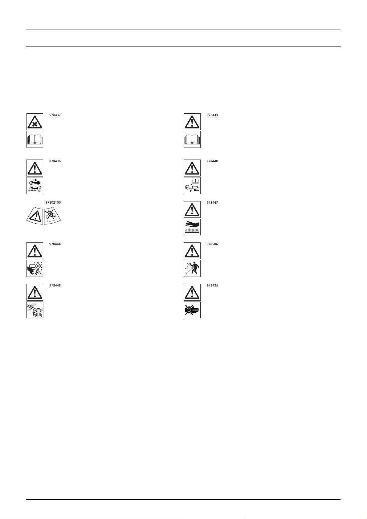
Explanation of Labels
The labels on the sprayer are designating potential dangerous areas on the machine. Operators, or anyone in close range of
the sprayer, must respect these warnings!
The labels should always be clean and readable! Worn or damaged labels must be replaced with new ones. Contact your
HARDI dealer for new labels.
Note that not all labels shown hereafter will apply to your sprayer - this depends on the sprayer model which labels apply.
Chemical handling!
Carefully read the informations about
chemical preparation before handling the
machine. Observe instructions and safety
rules when operating.
Service!
Turn off the engine and remove ignition key
before performing maintenance or repair.
Risk of death!
Do not attempt to enter tank.
Risk of injury!
Do not open or remove safety shields while
engine is running.
Risk of injury!
Service!
Carefully read the Instruction Book before
handling the machine. Observe instructions
and safety rules when operating.
Service!
Tighten to the torque according to instruction
book.
Risk of burn!
Stay clear of hot surfaces.
Risk of injury!
Flying objects - keep a safe distance from the
machine, as long as the engine is running.
Risk of injury!
Keep sufficient distance away from electrical
power lines.
Keep hands away.
12
Page 13

2 - General Safety Instructions
Risk of squeezing!
Stay clear of raised and unsecured loads.
Risk of squeezing!
Keep hands away, when parts is moving.
Risk of sprayer tipping over!
Be aware when disconnecting the sprayer.
Not for drinking!
This water must never be used for drinking.
Lifting point! Lifting point!
Risk of squeezing
Never reach into the crushing danger area as
long as parts are moving.
Risk of falling off!
Do not ride on platform or ladder.
Grapping area!
Manual handling of the boom etc.
Not for drinking!
This water must never be used for drinking.
Load index!
Max. permitted load rating is 164 at 40 km/h
or 5000 kg.
EasyClean filter service!
Open and clean filter monthly.
13
Page 14

2 - General Safety Instructions
Safety and Protection Equipment
Safety at Start-up
Each time before the sprayer is started up, all the safety and protection equipment must be properly attached and fully
functional. Check all safety and protection equipment regularly. Repair or replace the equipment as needed.
Faulty Safety Equipment
Faulty or disassembled safety and protection equipment can lead to dangerous situations.
14
Page 15

2 - General Safety Instructions
Informal Safety Measures
Additional Safety Instructions
Together with the safety information in this Instruction Book, also comply with the general and national regulations related to
A. Accident prevention
B. Environmental protection
C. The applicable workplace safety.
Follow these regulations, especially when
• driving on public roads and routes. Comply with the appropriate statutory road traffic regulations. These vary from
country to country, and there may be local regulations which need to be followed.
• local law demands that the operator is certified to use spray equipment.
• using pesticides or liquid fertilizer. Make sure you understand the information from the supplier regarding their use.
15
Page 16

2 - General Safety Instructions
Operator Training
Authorized Persons
Only those people who have been trained and instructed may work with/on the sprayer. The operator must clearly specify
the responsibilities of the people in charge of operation and maintenance work.
People being trained may only work with/on the sprayer under the supervision of an experienced operator.
Activity Person
Loading / Transport X X X
Commissioning 0X 0
Setup and tool installation 0 0 X
Operation 0X 0
Maintenance X X X
Troubleshooting and
fault elimination
Disposal X 0 0
Symbols: X - permitted, 0 - not permitted.
Person especially
trained for the activity
X0 X
Tra ine d
1)
operator
Person with specialist
2)
training (specialized workshop)
3)
1. Persons who can assume a specific task, and who can carry out this task for an appropriately qualified company.
Examples of these persons are truck drivers, machinery dealer and scrap dealers (depending on the activity).
2.
Persons who have been instructed in their assigned tasks and in the possible risks in the case of improper behaviour, who
have been trained if necessary, and who have been informed about the necessary protective equipment and measures.
Examples of these persons are customers, farmers and farm workers.
3.
Persons with specialist technical training shall be considered as a specialist. Due to their specialist training and their
knowledge of the appropriate regulations, they can evaluate the work with which they have been appointed to and detect
possible dangers. E
xamples of these persons are sprayer importers, dealers and service engineers and service
technicians.
Comment:
A qualification equivalent to specialist training can be obtained from several years of experience in the relevant field.
If maintenance and repair work on the sprayer is additionally marked "Workshop work", or a similar marking, only a
specialized workshop may carry out such work. The personnel of a specialized workshop shall possess the appropriate
knowledge and suitable aids (tools, lifting and support equipment) for carrying out the maintenance and repair work on the
sprayer in a way that is both appropriate and safe.
16
Page 17

2 - General Safety Instructions
Safety Measures in Normal Operation
Protection Equipment
Only operate the sprayer if all the safety and protection equipment is fully functional.
Check the sprayer at least once a day for visible damage and check the function of the safety and protection equipment.
17
Page 18

2 - General Safety Instructions
Residual Energy
Possible Dangers
Note that there may be residual energy from mechanical, hydraulic, pneumatic and
Use appropriate measures to inform the operators.
Prevent any accidents from happening due to residual energy.
Below are some examples on where the sprayer’s residual energies may be present.
Mechanical Energy
• springs under tension
• weights exposed to gravity
Hydraulic Energy
• trapped oil under pressure in cylinders, hoses and accumulators
• heat from cylinders and oil tank.
Pneumatic Energy
• air tank
• air activated brake system
• pressure dampers for fluid system
Electric Energy
• energy stored in capacitors
• tractor battery
electric / electronic
parts on the sprayer.
18
Page 19

2 - General Safety Instructions
Service and Maintenance Work
Statutory Inspection
A surveyor must complete a statutory inspection of the tractor and sprayer prior to connecting the two. However, the rules
often allow the tractor and the sprayer to be inspected separately before being connected.
Contact your local HARDI dealer for more information, before using the sprayer the first time.
Preventive Measures
Before carrying out service and maintenance work, secure all media against unintentional start-up. This goes for:
Hydraulic system
• set the tractor’s hydraulic levers in neutral position to relieve oil pressure
• turn off the tractor and remove the ignition key
• dismount the hydraulic hoses connected from the tractor to the sprayer.
Electric system
• turn off the tractor and remove the ignition key
• dismount the electric cables from the tractor’s battery.
Fluid system
• turn off the tractor and remove the ignition key.
Compressed air
• turn off the tractor and remove the ignition key
Carry out prescribed service, maintenance and inspection work in due time. This will help to eliminate faults on the sprayer,
including safety related functions.
Carefully fix and secure larger components to lifting gear when carrying out replacement work.
Check all the screw and bolt connections for firm seating. On completion of the maintenance work, check the function of the
safety devices.
19
Page 20

2 - General Safety Instructions
Design Changes
Operator Limitations
You may make no changes, expansions or modifications to the sprayer without an authorization from HARDI. This also
applies when welding support parts.
Any expansion or modification work shall require the written approval from HARDI. Only use modification and accessory
parts approved by HARDI, so that the type approval or other design approvals remain valid in accordance with national and
international regulations.
Vehicles with an official type approval, or with equipment connected to a vehicle with a valid type approval, or approval for
road transport according to the local road traffic regulations, must be in the state specified by the approval.
It is strictly forbidden to
• drill holes in the steel frame or in the running gear
• increase the size of existing holes in the steel frame or in the running gear
• weld support parts.
Risk of crushing, cutting, catching, squeezing, getting trapped, being drawn in or being struck by sprayer parts due to the
failure of support parts.
Spare Parts, Wear Parts and Aids
Immediately replace any sprayer parts which are not in a perfect state.
Only use genuine HARDI spare and wear parts or those approved by HARDI, so that the type approval remains valid
according to the national and international regulations. The use of spare and wear parts from third parties does not
guarantee that they have been constructed in a way as to meet the requirements placed on them.
HARDI accept no liability for damage caused by the use of non-approved spare parts, wear parts or aids.
20
Page 21

Cleaning and Disposal
Environmental Protection
Carefully handle and dispose of any materials used, in particular
• when carrying out work on oiled or lubricated sprayer parts.
• when cleaning using solvents.
2 - General Safety Instructions
21
Page 22

2 - General Safety Instructions
Workstation
Intended Place for Operator
There may be only one person sitting in the driver's seat of the tractor connected to the sprayer. This is the intended
workstation for operating the sprayer.
Risks of Non-Compliance
During the operation or transport of the sprayer:
If another person disturbs or interferes with the operator, or if the operator is trying to operate the sprayer from places other
than the tractor’s driver seat, can result in:
• risk of the operator loosing his ability to operate the vehicle correctly
• risk of fatal accidents while driving
• risk of damages to the tractor, sprayer and foreign objects while driving
• risk of inefficient spraying due to incorrect operation of the sprayer.
• risk of the operator loosing his concentration and focus on operating the vehicle correctly
22
Page 23

If the Safety Information is Ignored
Possible Risks and Dangers
Non-compliance with the safety information
• can pose a danger to people, to the environment and to the sprayer
• danger to people through non-secured working areas
• danger to people through mechanical and chemical influences
• failure of important sprayer functions
• failure of prescribed methods of maintenance and repair
• leakage of hydraulic fluid or spray fluid to the environment
• can lead to the loss of all warranty claims.
2 - General Safety Instructions
23
Page 24

2 - General Safety Instructions
Safety Information For Operators
General Safety and Accident Prevention
Before use or starting up the sprayer and the tractor, always check the
• roadworthiness
• operational safety
Risk of crushing, cutting, catching, squeezing, getting trapped, being drawn in or being struck by sprayer parts due to
inadequate roadworthiness and operational safety.
Beside these instructions, comply with the generally applicable national safety and accident prevention regulations.
The warning symbols and other labels attached to the sprayer provide important information on safe sprayer operation.
Compliance with this information is in the interests of your safety.
Keep the spray boom in folded position, whenever the sprayer is not coupled to a tractor. Unfolding the boom on an
uncoupled sprayer will shift the balance point of the sprayer causing a risk of overturning.
Before driving off and starting up the sprayer, check the immediate area of the sprayer - look out especially for children and
instruct them and other unauthorized persons to stay out of reach of the sprayer. Ensure that you can see clearly.
Drive in such a way that you always have full control over the tractor with the attached sprayer. In d oing so, take your personal
abilities into account, as well as the road, traffic, visibility, weather conditions and the driving characteristics of the tractor and
of the connected sprayer.
Slow down when driving in uneven terrain or when making sharp turns, as the sprayer might be in risk of turning over.
It is forbidden to ride on the sprayer or use it as a means of transport.
It is forbidden to stay in the working area of the sprayer’s drawbar, on the sprayer’s platform or behind the operating area
(the tractor), unless the hydraulic pressure to the sprayer has been switched off.
Only authorized persons are allowed inside or outside the tractor cabin during operation.
Keep persons, children and animals away from the operation areas of the sprayer and from the sprayer’s equipment. Be
careful when manoeuvring the sprayer, especially when reversing, as there is a risk of hitting people or surroundings.
Avoid eating, drinking or smoking while spraying or working with equipment contaminated with chemicals.
The chemicals used for spraying are dangerous to your health! In case of ingestion, poisoning or damages to your skin or
face, immediately seek medical advice. Remember to identify the chemicals used.
Coupling and Uncoupling the Sprayer
Only connect and transport the sprayer with tractors suitable for the task. See the section “Technical Specifications” in this
book to make sure that the tractor matches the requirements to operate the sprayer.
When coupling sprayers to the tractor's three-point linkage, the linkages of the tractor and the sprayer must always be the
same.
Connect the sprayer to the prescribed equipment in accordance with the specifications.
When coupling sprayers to the front or the rear of the tractor, the following may not be exceeded:
• the approved total tractor weight
• the approved tractor axle loads
• the approved load capacities of the tractor tyres
• the approved load capacities of the tractor hitch points.
Secure the tractor and the sprayer against rolling unintentionally before coupling or uncoupling the sprayer.
It is forbidden for people to stand between the sprayer to be coupled and the tractor, while the tractor is moving towards
the sprayer.
24
Page 25

2 - General Safety Instructions
Any helpers may only act as guides standing next to the vehicles, and helpers may only move between the vehicles when
both are at a standstill.
Before connecting the sprayer to or disconnecting the sprayer from the tractor's three-point linkage, secure the operating lever of
the tractor hydraulic system, so that unintentional raising or lowering is prevented.
When coupling and uncoupling sprayers, move the support equipment (if available) to the appropriate position (check
stability and strength of the support).
When actuating the support equipment, there is a risk of injury from crushing and cutting points.
Be particularly careful when coupling the sprayer to the tractor or uncoupling it from the tractor. There are crushing and
cutting points in the area of the coupling point between the tractor and the sprayer.
It is forbidden to stand between the tractor and the sprayer when actuating the three-point linkage.
Coupled supply lines
• must yield to all movements while cornering without tensioning, kinking or rubbing
• must not rub against other parts.
Ropes or cords releasing quick couplings must hang loosely, and they must not release themselves when lowered.
Also ensure that uncoupled sprayers are stable.
Use of The Sprayer
Before starting work, ensure that you understand all the equipment and actuation elements of the sprayer and their
function. There is no time for this when the sprayer is already in operation.
Only wear tight clothes. Loose clothing increases the risk of being caught by the drive shaft / PTO.
Only start-up the sprayer, when all the safety equipment has been attached and in the safety position.
Comply with the maximum load for the connected sprayer and the permissible axle and drawbar loads for the tractor. If
necessary, drive only with a partially filled tank.
It is forbidden to
• stand in or near the working area of the sprayer
• climb the sprayer
• stand or sit on the sprayer
• stand in the turning and swivel range of the sprayer.
There are crushing and cutting points at externally actuated sprayer points, e.g. hydraulic cylinders.
Only actuate externally actuated sprayer parts when you are sure that no one is standing within the prescribed safety
distance.
Before leaving the tractor:
• lower the spray boom to around waist height above the ground or lower, or
• fold the spray boom into the transport position
•
turnoff the tractor engine
• remove the ignition
When use of the TurboFiller has ended, make sure that all manifold handles are closed / deactivated.
If parking or stopping the tractor with the sprayer pump running, always keep the sprayer under supervision.
key
.
25
Page 26

2 - General Safety Instructions
Road Transport
When driving on public roads or highways with the sprayer coupled to the tractor, the following instructions must be
followed. Failure to do so will create a risk of traffic accidents and fatalities!
Comply with the national or local road traffic regulations when using public roads and highways.
When driving in areas with special rules and regulations for markings and lights on sprayers, you should observe these and
equip your sprayer accordingly.
Checking the vehicle
Before transporting the sprayer on a road, complete the following check points for the tractor and sprayer.
1. Spray boom is folded and resting in transport brackets with the intended locks engaged.
2. Engage transport locks on the steering cylinders.
3. Supply lines for hydraulic, electric and pneumatic systems (if installed) are correctly connected.
4. Parking brake is completely disengaged. Safety line is secured (if applicable).
5. Hydraulic pressure from tractor to sprayer is turned off.
6. PTO drive is turned off.
7. Hitch bolt(s) between tractor and sprayer must be secured with a linchpin or other appropriate means.
8. If the sprayer is coupled onto a lift link drawbar, the lower link should be laterally fixed.
9. Traffic lights and reflectors are in good working order, clean and free from damages.
10. Signs or markings on the vehicle regarding road transport are correctly placed and visible.
11. Brakes are in good working order and free from visible damages.
12. Tyre pressure is correct according to the load.
13. No cables or other parts must be strained or caught in the tractors wheels when cornering.
14. Crop residues and dirt are removed.
15. All moveable or loose equipment are securely latched or stowed away in the designated compartments.
Ensure that the tractor has sufficient steering and braking power. If necessary, use front weights to the tractor in a stable
position.
Any sprayers and front/rear weights connected to the tractor influence the driving behaviour and the steering and braking
power of the tractor.
The front tractor axle must always be loaded with at least 20% of the tractor’s empty weight, in order to ensure sufficient
steering power.
Always fix the front or rear weights to the intended fixing points according to regulations.
Comply with the maximum load for the connected sprayer and the approved axle and drawbar loads for the tractor.
The tractor must guarantee the prescribed brake delay for the loaded vehicle combination (tractor plus connected sprayer).
When turning corners with the spr ayer connected, take the broad load and balance weight of the sprayer into account. Slow
down as needed to avoid tilting or overturning of the vehicle, especially on sloping roads.
If the sprayer is fixed to the tractor's three-point linkage or lower links, ensure sufficient side locking of the tractor lower links
before driving off.
Before driving off, secure the operating lever of the three-point hydraulic system against the unintentional raising or
lowering of the connected sprayer.
Check that the transport equipment, e.g. lighting, warning equipment and protective equipment, is correctly mounted on
the sprayer.
Carry out a visual check that the upper and lower link pins are firmly fixed with linchpins against unintentional release.
Adjust your driving speed to the prevailing conditions.
26
Page 27

Before driving downhill, switch to a low gear.
2 - General Safety Instructions
Before driving off, always switch off independent wheel braking on the tractor (lock the
Do not use the sprayer as a means of transportation of people or goods.
No one is allowed outside the tractor cabin during road transport, as this can lead to fatalities.
The tractor driver must not be disturbed by other people in the cabin during driving.
Hydraulic System
The hydraulic system is operating under a high pressure.
Ensure that the hydraulic hose lines are connected correctly.
When connecting the hydraulic hose lines, ensure that the h ydraulic system is depressurized on both the sprayer and tractor
sides.
The operator controls in the tractor used for hydraulic and electrical movements of components must stay unlocked, e.g. for
folding, swivelling and pushing movements. The movement must stop automatically when you release the appropriate
control. This does not apply to equipment movements that
• are
continuous
• are automatically controlled
• require a floating position or pressed position to function.
Before working on the hydraulic system:
pedals).
• lower the
• turn off / depressurize the hydraulic system
• turn off the tractor
• engage the parking
• remove the ignition
Have the hydraulic hose lines checked at least once during a calender year by an expert to ensure that they are in safe working
order.
Replace the hydraulic hose lines if they are damaged or worn, which is when
• it is leaking
• reinforcement material inside the hose is visible due to cracks in the outer layers.
Only use genuine HARDI hydraulic hose lines.
The hydraulic hoses should not be in use for longer than 5 calender years, including any storage time of maximum 2 years.
Even with proper storage and approved use, hoses and hose connections are subject to natural ageing, thus limiting storage
time and the time of use. However, it may be possible to specify the length of use from experience values, in particular when
taking the risk potential into account. In the case of hoses and hose connections made from thermoplastics, other guide
values may be decisive.
Never attempt to plug leaks in hydraulic hose lines using your hand or fingers. Escaping high pressure fluid (hydraulic oil) may
pass through the skin and ingress into the body. RIsk of infection and serious injuries.
spray boom to its lowest position or into the transport position
engine
brake
key
.
If you are injured by hydraulic oil, contact a doctor immediately.
When searching for leaks, use suitable aids to avoid the serious risk of infection and injury.
27
Page 28

2 - General Safety Instructions
Electrical System
When working on the electrical system, always disconnect the tractor’s battery.
When disconnecting the battery, disconnect the negative terminal first, followed by the positive terminal.
When connecting the battery, connect the positive terminal first, followed by the negative terminal.
Always place the appropriate cover over the positive battery terminal. If there is accidental earth contact, there is a risk of
explosion.
If climbing onto the sprayer during service work, be aware of the low voltage danger from electric components.
Only use the prescribed fuses. If the fuses used are too highly rated, the electrical system will be destroyed. Risk of fire.
The spr ayer may be equipped with electr onic components whose functions are influenced by electromagnetic interference
from other units. Such interference can pose risks to people, if the following safety information is not followed.:
• If retrofitting electrical units and/or components on the sprayer with a connection to the on-board power supply, the
user is responsible for checking whether the installation might cause faults on the vehicle electronics or other
components
28
Page 29

2 - General Safety Instructions
Field Sprayer Operation
Observe the recommendations from the manufacturer of the crop protection product in respect of
• personal protective equipment
• warning information on exposure to crop protection products
• regulations on dosing, applications and cleaning.
When there will be exposure to the crop protection product, wear the proper personal protective equipment. This may differ
depending on the chemical being sprayed. Follow the local law. Wash and change clothes after spraying. Wash tools if they
have been contaminated.
Observe the information in the national plant protection law.
Keep hoses, pipes or other lines closed, when they are under pressure.
Only use genuine HARDI hoses and hose clamps for replacement, which stand up to chemical, mechanical and thermal
requirements.
The rated volume of the spray liquid tank must not be exceeded during filling. If overfilling, some sprayer functions may be
disabled. However, the main tank is a little oversized to allow for foaming.
When using tractors with a cab with ventilation fans, replace the fresh air filters with activated carbon filters.
Observe the information on the compatibility of crop protections and substances for the field sprayer.
Be aware that some crop protection products have a tendency to stick together or settle when being mixed.
Do not fill the sprayer with water from bodies of water, which are open to the public. This is for the protection of people,
animals and the environment due to the risk of contamination.
Only fill the sprayer using a free flow of water from the mains water supply or from an external water tank.
Environmental Precautions
It is essential to reduce the environmental impact of plant protection chemicals to a minimum. Particularly the soil, subsoil
water, streams, lakes, flora and fauna must be in focus. Contamination of subsoil water must be prevented by paying
particular attention to avoidance of spot contamination of the soil in connection with filling and washing and parking of the
sprayer.
If any concentrated chemicals are spilled on the soil, the contaminated soil should be removed and sent for cleaning at a
capable facility. Follow local regulations regarding disposal. This must be done to avoid seepage of chemicals to the subsoil
waters. Avoid spillage - use the chemical filling device for filling the sprayer with chemicals.
Do not overfill the main tank. The rated volume inside the main tank is stated with large printed numbers on the outside of
the tank. If overfilling, the spray liquid could leak from the sprayer causing contamination of the soil.
Before filling the sprayer with plant protection chemicals, the sprayer must be calibrated to apply the precise dose rate
selected. The important input sensors are the flowmeter and the speed sensor.
It is recommended to establish a proper filling and washing location with hard, impenetrable surface drained to a receptacle
if the sprayer is always filled or cleaned on the same spot at the farm. If a washing/filling location is NOT available, the
following precautions should be taken:
• The sprayer should only be filled with clean water at the farm
• The plant protection chemicals must be added and mixed in the field to be sprayed
• Select a different location each time the sprayer is refilled.
29
Page 30

2 - General Safety Instructions
Service Work Precautions
Before carrying out any service work, all of the following instructions must be followed in order to prevent damages to the
sprayer, injuries and fatalities:
• do not walk under any part of the sprayer, unless it is secured. The spray boom is secured when placed in the transport
brackets
• if the spray boom is folded up and resting in the transport brackets for service, check visually that the paralift locks are
engaged (the boom is locked in place)
• if the spray boom is unfolded for service, the boom must be lowered, until it reaches its end stop. Place strong trestles
under the boom for support or use a lifting crane for support
• never service or repair any equipment while it is operating
• any service work is preferable carried out on level ground with only authorized persons nearby
• depressurize the hydraulic system for the sprayer to prevent unintentional movements of the sprayer
• switch off the PTO
• switch off the tractor and remove the ignition key to prevent unintentional starting
• activate the parking brake to prevent rolling
• put chocks in front of and behind the wheels to prevent rolling
• electric power must be disconnected from the sprayer
• any service work on electronic /electric parts must be carried out under dry conditions - no rain or splashes from water
or other liquids.
Cleaning
When cleaning nozzles and filters, lower the spray boom to around waist height above the ground. For safety reasons, do
not walk or stand below the boom or paralift during this cleaning work!
Dispose of oils, greases and filters in the appropriate
Cleaning of tanks:
• Due to toxic vapours from spray liquids in the main tank, climbing into this tank is very hazardous. Cleaning should only
be done from the outside.
• Refrain from entering the main tank.
• Refrain from inspecting any of the tanks with the liquid pump running.
Rinse and wash equipment with clean water after use and before servicing.
way to protect the environment.
30
Page 31
General info
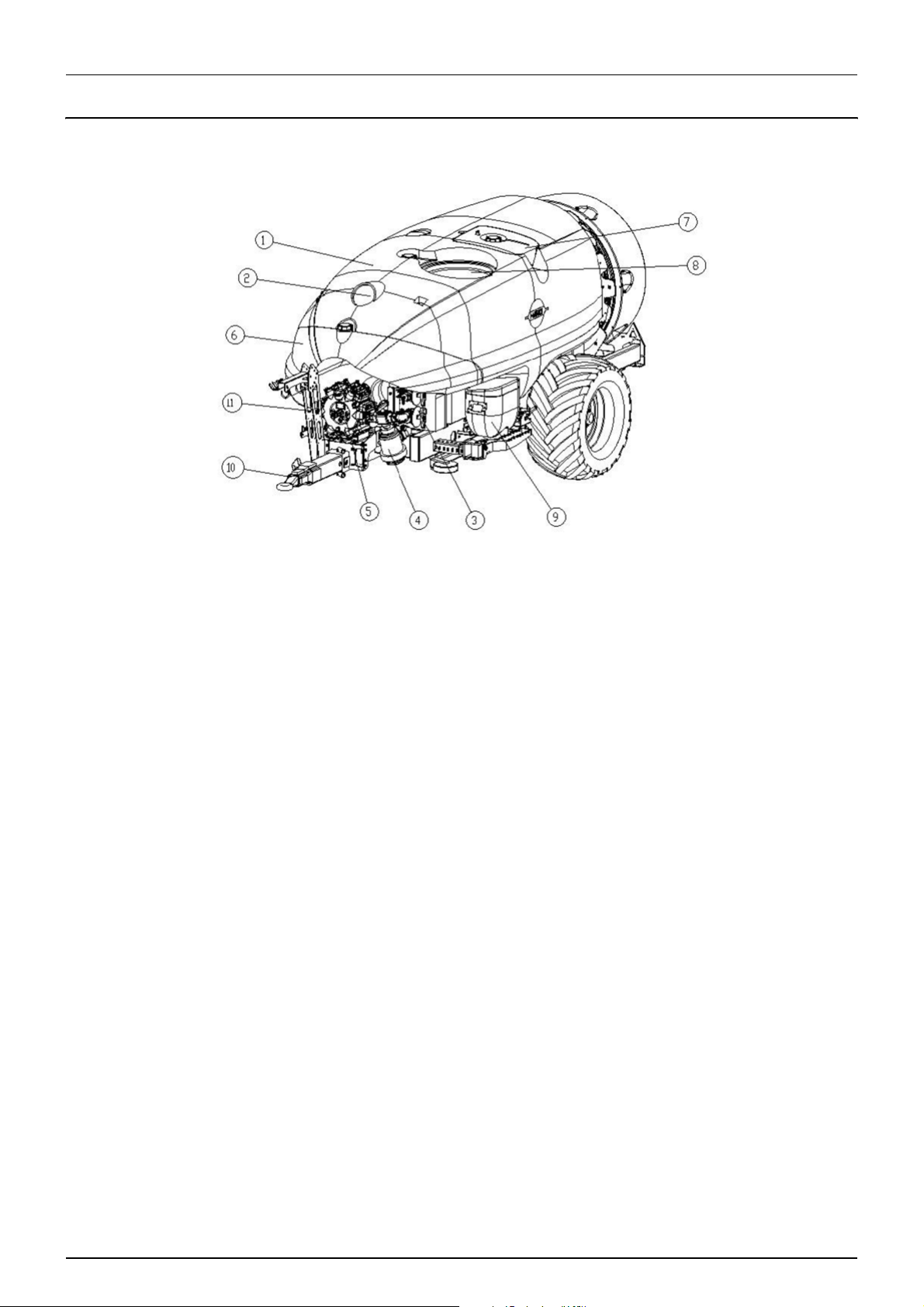
View
3 - Description
1. Main tank
2. Level indicator, optionally on top of the tank
3. Manifold valves
4. Suction filter
5. Pump
6. Rinsing tank
7. Clean water tank
8. Main lid and strainer
9. TurboFiller (Not used)
10. Drawbar
11. Operating unit
31
Page 32

3 - Description
14
15
17
12
13
18
13
16
12
19
20
21
17
16
12. Chassis
13. Fan house
14. Grid and air guide
15. Centre cover
16. Bumper and light bar
32
17. Gear box filling point
18. Air outlet
19. Spray line
20. Adjustable bottom deflector
21. Operating unit and hydraulic valves
Page 33

3 - Description
Use of the mist blower
The HARDI mist blower is designed for applying chemical products used for crop protection. This equipment may only be
used for this purpose. The use of this equipment for other purposes is not allowed. If there is no special law in your region
which obliges the user to have a permit, it is recommended to be well-prepared for protecting crops in a correct way and
for handling chemical products safely so as to avoid unnecessary risks to people and the environment while spraying takes
place.
For environmental issues the air kit is offered with option to close either left or right side of the air stream from the blower.
These blinds, are mandatory in some sensitive areas, to avoid chemical contaminated air, blowing towards river sides and
water channels
Roadworthiness
When driving on public roads and other places where the road safety code or where there are other special rules and
regulations for marking and lights on machinery, the machine must be equipped to comply with these regulations.
ATTENTION! For models not fitted with brakes the maximum speed is 25 km/h and 40 km/h for those with. This could
μ
vary according to local legislation. Contact your local authorities to find out the current maximum speed limits.
Identification plate
The identification plate is located on the front right-hand side of the
machine and is riveted to the chassis. It indicates the make, model, serial
number, and date of manufacture.
The serial number is also engraved onto the chassis. The number is
found above the identification plate, as indicated in the picture. The
serial number consist of five digits.
The serial number is also engraved onto the chassis. The number is
found above the identification plate, as indicated in the picture. The
serial number consist of five digits.
HARDI AUSTRALIA PTY. LTD.
SERIAL NUMBER
Chassis
The monoblock cold-pressed metal chassis is highly durable and built to last under everyday use under extreme conditions.
It is manufactured using only the most advanced laser cutting and automated soldering processes. To protect against
corrosion it is coated with a polyurethane bi-component paint on top of a highly adherent, steel blasted base.
33
Page 34

3 - Description
Tank
The main tank made of impact-proof, UV-resistant and chemical resistant polyethylene has a purposeful design with no
sharp corners for easy cleaning. Nominal contents are, 2000, 2300, 3000 or 4000 l. A large, easy to read tank contents indicator
is placed on the front - right-hand side and another one is placed on the left side. First one is visible from the tractor cabin.
The filling hole is accessible from the left-hand side. This ensures an easy access for the filling of spray liquid, cleaning of the
tank, etc. The mistblower is equipped with a clean water tank integrated with the main tank design.
34
Page 35

3 - Description
Liquid system
General information
All the suction system functions are operated via a 3-way valve. The pressure valve is also to be found in the pressure circuit.
The low pressure circuit is called HLC (Hardi Liquid Circuit).
The liquid circuit
Consist of manifold system in the working zone (front part) where pressure manifold receives liquid from the pump, and
distributes to the different options on the sprayer – to the operating unit, to the bottle cleaner, to the Powder mixer in
strainer etc., all according to configuration of options. The suction manifold in same area allows suction from main tank,
rinsing tank (only on Zaturn) or external water source, if fitted, depending on its configuration.
The pressure side of the liquid circuit is fitted with a safety valve to protect the circuit against misuse of excessive pressure.
See chapter “Safety valve”
Diaphragm pump
Pumps with a diaphragm: Models 364/7 or 464/10
They are low pressure and robustly built. Use only grease for lubrication. This type of pump is self-priming, works without oil
and can run dry as long as necessary.
Valves
The suction valve is located above the pump and is used to select where to suck liquid from. Either suction from the main
tank for spraying or from the rinse tank (Rinse tank only available on Zaturn) for internal cleaning of the liquid circuit. The
function is selected by turning the handle of the valve towards the desired function.
ATTENTION! If one of the handles is too tight - or too loose (=liquid loss) - the valve needs to be serviced. For more
μ
information, see section on “Maintenance”.
Valves and symbols
The valves are identified by coloured discs fitted on the valves themselves. The symbols correspond to the optional
accessories, and are located on the discs for quick identification and handling. To activate/open a function, turn the lever to
the desired function.
ATTENTION: Only the functions to be used should be activated – the other valves should always be kept closed.
μ
ATTENTION: If the handle of a MANIFOLD valve is too tight – or too loose (loss of fluid)– the valve needs to be serviced.
μ
For more information, see the section on ‘Maintenance’.
35
Page 36

3 - Description
Manifold system (Zaturn only)
The functions of the spray circuit are operated via the centrally
situated MANIFOLD with colour coded plates and pictorial symbols
for easy operation.
The modular valve system facilitates the addition of optional extras
on both pressure (A) and suction (B) for agitation and for rinsing
nozzle (optional equipment).
Agitation / Tank rinse valve (Zaturn only)
The “Agitation/ Tank rinse valve” can be adjusted for desired agitation,
or tank rinse. In vertically position the valve is off.
ABABA
B
Pressure valve (Zaturn only)
The pressure can be set to pressure to boom or pressure to main tank.
The valve is off in vertical position.
Suction valve (Zaturn only)
The suction valve can be set to suction from rinse tank or suction
from main tank. The valve is off in horizontal position.
36
Page 37

Pressure manifold (Mercury only)
This steel part is located at the front of the machine, beside the control
unit. Agitation, tank flushing (according to model) and the powder
mixer are activated from this manifold using the ball check valves.
It also includes a free ball check valve for connecting the spray gun and
the safety valve of the pressure circuit.
3-way suction valve (Mercury only)
This valve is located above the suction filter and the flow passes through
it before reaching the suction MANIFOLD. It enables the selection
between suction from the main tank or from the fast filling device.
ATTENTION! If any of the valve handles are too stiff –or too loose
μ
(loss of fluid)– the valve needs to be serviced. For more
information, see the section on ‘Maintenance’.
3 - Description
Agitator (Zaturn)
At the front and on each side of the inside of the tank there are two
ventury-shaped agitators. The agitators activated by a valve on the
pressure manifold.
Each agitator has a Ø 3mm nozzle (D).
Agitator (Mercury)
There is a trumpet-type agitator at the back and on each side inside the
tank. These agitators are activated by one of the ball check valves in the
pressure manifold.
In the inner housing (A), they include a 2.5 mm diameter restrictor as
standard. For better tune-up of the machinery, two 5 mm restrictors are
also supplied in case of need.
D
37
Page 38

3 - Description
Rate Controller DB3610
1415
10
139 11
12
1-2-3-4. Fluid section. Odd on left / Even on right
5-6-7-8. Hydraulic selectors
9. Menu/Left
10. Up
11. Escape/Right
12. Down
13. Enter/Regulator
1 2
3 4
5 6
7 8
14. ON-OFF sonars/Screen views
15. ON/OFF/Pause
38
Page 39

3 - Description
Axial blower units
Technical information
The air kit fitted on the HARDI ZATURN mist blowers are the AG820. The air kit fitted on the HARDI MERCURY can be either
a SF65 or SF85. The kits have a polyethylene housing and fan blades made of a hardened synthetic material. Their
aerodynamic shape offer a high quantity and perfect air distribution, low noise levels and low power consumption when
adjusted to standard levels. The fan clutch enables a smooth start and stop.
AG820 and SF65
The air kits are fitted with a grid with air guides at the air intake, which forms the air flow before reaching the fan, to decrease
the imbalance in the airflow. The fan is either 820 or 920mm of diameter and is fitted with blades made of a hardened
synthetic material. This reduces the power consumption to a minimum as a result of low material density. There is a channel
between the air intake and the cone of the air kit which increases the air speed through the outlet, and ensures that a high
uniformity in air distribution is achieved.
AG
SF
DANGER! Newerexceed 540 r.p.m. on the tractor P.T.O.! The fan may explode if overspeeded!
€
DANGER! Keep away from the air inlets and outlets while the fan is on. Some objects may be shot out of the air outlet
€
or a piece of clothing could be sucked into the air inlet.
WARNING! The fan is the most dangerous part of the machine. Do not try to replace any of the parts without
±
consulting your HARDI dealer first. Any service job or modifications on fan and air kit is to be carried out by your HARDI
dealers qualified technicians.
39
Page 40

3 - Description
Air flow of axial blower Mercury
Blower unit Speed Gear ratio Blade angle Power Flow
SF65 1st low 1 - 3.4 35º 22 kW 44000 m3/h
40º 24 kW 58000 m3/h
45º 32 kW 63000 m3/h
2nd. high 1 - 4.4 35º 26 kW 52000 m3/h
40º 28 kW 66000 m3/h
45º 46 kW 72000 m3/h
Blower unit Speed Gear ratio Blade angle Power Flow
SF85 1st low 1 - 3.4 35º 29 kW 69000 m3/h
40º 31 kW 77000 m3/h
45º 35 kW 82000 m3/h
2nd. high 1 - 4.4 35º 35 kW 77000 m3/h
40º 36 kW 86000 m3/h
45º 54 kW 93000 m3/h
Air flow of axial blower Zaturn
Blower unit Speed Gear ratio Power Flow
AG820 1st low 1 - 3.5 27 kW 43000 m3/h
2nd. high 1 - 4.4 33kW 50000 m3/h
Protective grid
The air kits are fitted with protection grids. They are fundamental for
avoiding accidents and for stopping foreign bodies from getting inside
the air kit.
A
Tractor drivers seat is the intended working place during
μ
operation.
This product is designed to be used in agriculture orchard
μ
application.
Invers air inhalation
A is air inhale and B is air out let
DANGER! It is strictly forbidden to use the blower unit without the
€
protective grid.
B
DANGER! Do not approach the fan when in use.
€
DANGER! Do not introduce foreign bodies through the grid,
€
regardless of whether the fan is in use or not.
DANGER! During the working day, protect your hearing from the
€
noise produced with EN 352-1:1992 approved hearing protection or similar.
DANGER! If you notice vibrations or unusual noise, stop the fan immediately and consult your HARDI dealer.
€
Do never pass 540 rpm on tractor PTO
€
40
Page 41

Deflectors
Axial air sprayer known as well as air sprayers can optionally be
equipped with mentioned deflectors.
3 - Description
Deflectors contribute to an increased efficacy in the spray job, as they
reduce drift, and provide direction of air and spray mist in direction to
the target, according to adjustment.
V
Gearbox
The AG820 and AG920 are fitted with a 2-speed gear box with a neutral
position. The front and lower area of the gear box are attached to the
chassis. It is fitted with a speed selector that prevent from jumping out
of gear when engaged.
The speed ratios are following:
1st speed, low gear: 1 – 3.6
2nd speed, high gear: 1 – 4.4
DUO T
41
Page 42

3 - Description
Fan
The axial fan has syntetic, impact proof blades resistant to high and low
temperatures as well as chemical products.
The blades have 4 different angle settings to adjust the air flow. To
change the angle see the section “Adjusting the fan”. (page 5.1).
Specific for SF fans
After changing pitch, the fan needs to be balanced.
Position P1 (35º) must coincide with C1, in other words the first groove on
the fan blade with the first groove on the crown.
Second position P2 (40º, standard factory setting) must coincide with C2.
Third position P3 (45º) must coincide with C3. After changing pitch, the
fan must be calibrated, either at the factory, of by certified shop, under
instruction of the factory (HARDI).
42
Page 43

3 - Description
Filters
The suction filter captures impurities in the fluid from reaching the pump. It is located on the left side of the front of the
mistblower, beside the pump.
The pressure filters are assembled on the back of the chassis, just behind the blower unit. These filters are assembled as
standard on all models.
It is essential that all filters perform their function correctly, so they should be checked regularly. Pay special attention to the
filter/mesh size combination.
Suction filter
This filter is assembled under the 3-way valve belonging to the suction
circuit.
The standard filtering element is white and has a mesh size of 30
(0.58 mm). For more information on the mesh size, see the section on
‘Technical specifications’.
Pressure filters
The pressure filters are located in the bumper, beside the air discharge
nozzle. In the HLC circuit, the filters are manufactured from synthetic
material.
These filters must be in perfect conditions and cleaned regularly. Pay
special attention to the correct filter/mesh size combination. The mesh
size must always be smaller that the average of the nozzle total flow.
Powder mixer
This is used to rinse the filter basket intank’s filling hole when adding
powdered products that do not dissolve properly form lumps on
contact with the water in the tank.
After using the powder mixer it must be disengaged as it uses a large
amount of the available pump capacity.
43
Page 44

3 - Description
Centrifugal Blower Units (Turbines)
General information
The blower unit is located at the back of the machine. It contains a gearbox unit, blanking plate, casing, outlet hoses and
nozzles, turbine and clutch. There are two different turbine models: the steel model assembled in P540 and P540D
centrifugal blower units, and the aluminium model assembled in HF600 blower units.
ATTENTION! The clutch is one of the most important parts in the blower unit in terms of safety. Make sure that it is in
μ
perfect conditions (i.e. that it is not blocked, etc.). Otherwise, it could cause the blower unit to explode.
HF640D (TD3-P640 Double)
The air kit should adapt to the requirements of the booms width and crop in order to give the best application results. The
following section gives more details about the different pneumatic air kits available.
The letters HF640D means High Flow and Double, respectively. They have a polyethylene casing and turbines of 640 mm
diameter.
Components
D. Steel turbine D. Steel turbine
B. Polyethylene crankcase E. Gearbox
C. Clutch F. Chassis
A B
C
D
DANGER! UNDER NO CIRCUMSTANCES should you exceed 540 r.p.m. from the tractor PTO as there is a serious danger
€
of air kit explosion.
DANGER! STAY CLEAR of the air inlet and outlet while the turbine is in use. Foreign objects could be expelled fromthe
€
air outlet or parts of clothing could be sucked into the air inlet.
WARNING! The blower units are the most dangerous part of the machine. Do not attempt to alter any of its
±
components without checking with your nearest distributor first. Manipulating blower units to change their
characteristics should only be carried out by qualified personnel that has been expressly authorised by ILEMOHARDI
E F
44
Page 45

3 - Description
Air flow of HF640D centrifugal turbines
Blower unit Speed Gear ratio Blade angle Power Flow
HF640D 1st low 1 - 4.5 24 kW 27000 m3/h
TD3-P640 2nd high 1 - 5.7 36 kW 37000 m3/h
Protective grid
The blower units have protective grids fitted to the air inlets. They are
essential for avoiding accidents and preventing small stones, leaves
or other foreign bodies from entering the blower unit that could
cause damage inside the grid.
DANGER! It is strictly forbidden to use the blower unit without
€
the protective grid.
DANGER! Do not approach the fan when in use.
€
DANGER! Do not introduce foreign bodies through the grid,
€
regardless of whether the turbine is in use or not.
DANGER! During the working day, protect your hearing from
€
the noise produced with EN 352-1:1992 approved earmuffs or
similar.
DANGER! In the case of vibrations or knocking, stop the
€
turbine immediately.
45
Page 46

3 - Description
Gearbox
The HF540, HF540D and HF640D blowers have a two-speed gearbox
with neutral position.
Upper pos: High speed
Middle pos.: Neutral
Lower pos.: Low speed
DANGER! Do not attempt to engage or disengage the speed
€
with the PTO in operation.
HF 640D Turbines
The centrifugal blower units contain a galvanised steel turbine. The
difference between the single model and the double model is that
the double provides the same power as two single turbines
combined.
The position of the blades in this type of turbine is fixed. Their angle
cannot be changed like in axial fans.
The turbines are allowed to turn at a maximum of 540 r.p.m.
The clutch is at the centre of the turbines, which ensures smooth
startup and stops - see section “Clutch” for further information.
Clutch (All blower types)
The clutch is integrated at the centre of all the fan models and will
ensure a smooth start-up and stop of the fan. The clutch design may
vary from model to model, but the functioning and maintenance is
the same.
WARNING! The clutch is a vital part in the blower unit. Poor
±
condition could cause the blower unit to break or explode.
The condition of this part should be regularly checked. Please
carefully read the section on its ‘Maintenance’.
DANGER! The clutch is one of the most important parts in the
€
blower unit in terms of safety. Make sure that it is in perfect
conditions (i.e. that it is not blocked, etc.) Otherwise, it could
cause the blower unit to explode.
46
Page 47

Equipment
Ring drawbar
This is attached near the tractor’s rear axle. Before engaging the tractor
PTO (Power take-off ), make sure the drawbar pin is firmly in place and
secured, and that the tractor’s wheels do not touch the mistblower
when turning.
There needs to be a CV joint on the side of the tractor. The length of the
drawbar can be adjusted (see section “Adjusting the length of the
drawbar”).
Turnable drawbar
This is attached to the tractor’s lift arms. Before engaging the tractor PTO
make sure the diameter of the shaft fits the ball couplers at the lift arms.
Also make sure to fit the securing pins and check that the tractor’s
wheels do not touch the mistblower when turning.
Th is type o f coupl ing al lows n arrow turns, if a CV j oint is fitted at th e mist
blower’s power intake. The length of the drawbar can be adjusted (see
section “Adjusting the length of the drawbar”).
3 - Description
The turnable drawbars, model X and Y are fitted under the rear axle of
the tractor, a common arrangement on smaller fruit orchard models of
tractors. Important that the two stop bolt are tighten up, to avoid slack
Danger! Angle transmission shaft fitted. Tight turns with PTO engaged may damage the transmission shaft, the pump
€
crank shaft and induce huge vibrations through the gearbox. This may lead to severe damages on gearbox and/or
fan.
Wed ges
The wedges are located on the left-hand side of the machine. They
should always be carried in their support so they are available when
required.
47
Page 48

3 - Description
Boom
The boom fitted to the MERCURY COVAMAX has numerous features
that enable flexibility for operators when setting up and operating.
Some of the benefits are;
• Lift
• Fold
• Tilt
• Breakaway Arms
• Adjustable nozzle positioning and directing
• Low maintenance
Breakaway Arms
To minimise damage to equipment or crops should the boom collide
with an object, a breakaway feature is incorporated into the boom. A
pivoting hinge mounted on a rear spar of the boom centre allows the
boom tubes to independently move out should the boom arm come
in contact with an object.
Hydropneumatic spray system
The hydropneumatic system is medium-high pressure. This system takes
advantage of higher turbulence in the low-volume conical nozzle and
sprays the liquid with an even distribution. The air reaches high speed in
the spout, spraying the liquid in a fan.
There are three spout models with three or five nozzles. These two
models cannot be combined.
E. Spout with 3 nozzles.
F. Spout with 5 nozzles.
Where not all the nozzles are required in treating the crop, the nozzles
can be replaced for caps.
48
Page 49

General information
Unloading the mistblower from the truck
When unloading the mistblower from a van or truck with the aid of a
hoist or crane, use the lifting points shown in the illustration, and
make sure that the straps or cords used for the purpose are strong
enough.
DANGER! Do not stand underneath or beside the machine
€
when it is being loaded or unloaded.
4 - Sprayer setup
Before starting up for the first time
Although the metal parts of the mistblower have received a strong protective surface treatment, a film of anti-corrosion oil
(e.g. CASTROL RUSTILLO or SHELL ENSIS FLUID) should be applied to all metal parts to prevent the enamel from being
discoloured by the chemical products; it will also make it easier to clean the mistblower.
ATTENTION! This treatment should be repeated whenever the protective film wears off.
μ
Counterweights
Check whether a counterweight is required on the front of the tractor when coupled to the machinery to prevent excessive
rocking or an accident from occurring.
49
Page 50

4 - Sprayer setup
Mechanical connections
Adjusting the drawbar length
1. Place the jockey wheel in the position indicated in the photo.
2. Loosen the three bolts (A), located in the area where the drawbar
is connected in the chassis.
3. Remove the bolt (B).
4. Adjust the drawbar to the desired position.
5. Replace bolt (B), making sure that it passes through the holes in the
chassis and the shaft.
6. Tighten the bolts (A) and the locknut again.
Jockey wheel
The jockey wheel allows the mistblower to be coupled to or uncoupled
from the tractor. The illustration shows the position when the
mistblower is uncoupled from the tractor; when it is coupled, it will be
fastened to the left side of the mistblower chassis using two pins.
The height of the machine can be regulated by turning the handle (C).
Connecting the ring drawbar
This is attached to the standard clevis-type coupler closeto the tractor
body. Before connecting the PTO make sure that the drawbar is
correctly attached and secured, and that the tractor wheels do not
touch the mistblower when turning. A transmission shaft with CV joint
is required on the tractor’s side. It is possible to adjust the length of the
drawbar.
Adjust the drawbar if necessary as explained in another section
Connecting the articulated drawbar
This is attached to the tractors lower linkage arms. Before connecting
the PTO make sure that the diameter of the pins matches the ball
diameter on the lower links, that the snap locks are engaged and check
that the tractor wheels do not touch the mistblower when turning. Of
the three hitch types this is the one that permits the tightest turns, but
a transmission shaft with CV joint is then required on the mistblowers
power intake side. The length of the drawbar is adjustable.
Adjust the drawbar if necessary as explained in another section.
50
Page 51

Lock device on turnable drawbar
The turnable drawbars are fitted with a lock device, once down in
forward and horizontal position; the pivoting effect is very limited. If
the tractor has a weight 2 X the sprayer, it can be used in hilly
conditions, where risk of tumbling the sprayer exists, but it is
recommended to use the drawbar unlocked.
Adjusting the track width (only available on some model)
To adapt the track width to the terrain, a simple adjustment of the semiaxles needs to be performed.
Proceed as follows to correctly adjust the width:
4 - Sprayer setup
1. Raise the machine at the back so the wheels do not touch the
ground.
2. Loosen the two nuts and bolts (B) that fasten the axle inside the
housing.
3. Push the axle inwards or outwards, depending on whether greater
or less track width is required.
4. When the axle is in the correct position, tighten the bolts (A) and
the locknuts (B) again.
5. Repeat this operation with the other axle.
DANGER! Do not remove the axle from the housing more than that allowed. The correct position for the axle is when
€
the axle is properly fastened with the two bolts (b) in the housing.
Adjusting the axle position (Wheel base)
Depending the air kit fitted to the equipment and the adjustment made
to the chosen drawbar, the position of the axle may need to be adjusted
to improve the machine’s stability.
DANGER! Risk of personal injury. Before working underneath the
€
machine make sure it is lifted and supported properly! Never rely
on a hydraulic jack only.
Proceed as follows to correctly adjust the width:
1. Raise the machine at the back so the wheels do not touch the
ground.
2. Remove the semi-axles.
3. Loosen and remove the two bolts (A) that fasten the axle housing
on both sides of the frame.
4. The housing needs to fitted further back if the machine jumps at the front when empty.
5. Tighten the bolts (A) again when the housing is in the desired position.
6. Re-fit the semi-axles.
ATTENTION! Always retighten all bolts again after a few hours work.
μ
51
Page 52

4 - Sprayer setup
Connecting the transmission shaft
Initial installation of the driveshaft may involve having to cut the axle to
adapt it to the tractor to which it will be hitched. To hitch it for the first
time, proceed as follows:
1. Attach the mistblower to the tractor in such a way that the
distance between the PTO shaft and the mistblower pump is the
shortest possible.
2. Stop the engine and remove the ignition key.
3. If the driveshaft needs to be shortened, pull the two parts of the
shaft apart. Fit the two parts of the shaft, one to the tractor and the
other to the mistblower crankshaft and measure out the length
that needs to be removed. Mark the protection guards.
ATTENTION! The shafts must always have a minimum overlap of
μ
one third of their working length.
4. Cut both parts equally, using a saw. File the profiles afterwards to
remove burrs.
5. Grease the profiles and reassemble male fitting and female fitting.
6. Fit the shaft to the tractor PTO and to the mistblower pump shaft.
7. Place the input part towards the tractor. Fit the chains to prevent
the protection guards from rotating with the shaft.
ATTENTION! To ensure long life of the driveshaft and prevent
μ
possible damage to the equipment, try to avoid working at
angles of more than 15°.
52
Page 53

4 - Sprayer setup
Hydraulic connections
General information
Make sure that the couplings are clean before fitting them!
After pressing the brake pedal and when the system is filled with oil, check the level of hydraulic oil in the tractor and refill
if required.
DANGER! Testing the hydraulic system should be done with care. Air may have entered the system and cause sudden
€
movements.
DANGER! Oil leakage: Do not use your hands under any circumstances to locate a leakage in any point in the hydraulic
€
system. Due to the system’s high pressure, the oil could penetrate the skin.
53
Page 54

4 - Sprayer setup
Electrical connections
General information
If your equipment includes an electrical component, please note the
following information to correctly connect the equipment and to
prevent problems when working.
The voltage required by the electrical components is 12 V. Before
connecting any component, make sure that the polarity is correct.
Red wire = 12 V (+ positive)
Black wire = (- negative)
This is the standards for the majority of modern tractors. If your tractor
has another type of power supply connector, the supplied connector
will need to be removed and adapted to the tractor connector.
Operating unit
Find a place in the tractor’s cab where it is possible to fit the control
box so you can operate it as comfortable as possible. The most
recommended place is to the right of the driver’s seat.
The control box must be properly attached to prevent it from being
hit or from excessive vibrations.
The connector type is universal and it should be able to be
connected to any tractor. Do not connect into coincidently wires in
tractor cabin, as it will not secure stable power and current.
Minimum requirement: min 11V max 13 V Amp. Per SV section 2.5
Amp. Per CB section 0.75
As an emergency solution, remove the connector and splice the
wires directly to the battery, remember to have fuse in between.
ATTENTION! The control box must be properly attached to
μ
prevent it from being hit or excessive vibrations.
The connector type is universal and it should be able to be
connected to any tractor.
As an emergency solution, remove the connector and splice the
wires directly to the battery.
WARNING! Always remember: Red wire (+) Black wire (-)
±
DANGER! Always turn off any spray computer before you unplug the power supply and cable to the sprayer. Data
€
transmission must stop, before power supply is stopped.
54
Page 55

Rate controller
Rate controller DB 3610
Display
DB 3610
Fluid Box
FB 3610
4 - Sprayer setup
Power BOX
Hydraulic box
HB 3610
out put out put
The Job boxes for input and out put signals
55
Page 56

4 - Sprayer setup
Fluid circuit
Suction filter
The mesh size of the standard filter is 50 mesh. 80 and 100 mesh filters
are available and can be changed by opening the top lid of the filter.
Check the o-ring before replacing the lid and replace it if it is damaged.
ATTENTION! For better sealing between the lid and the o-ring,
μ
coat the area between the joint and the lid with grease. This will
make the O-rings seal and avoid suction of false air.
Diaphragm pump
Before starting to use the machine, make sure the diaphragm pump is
well greased to prevent wear.
The pump is greased from factory, but should be greased again during
bedding in.
56
Page 57

4 - Sprayer setup
Deflectors
ATTENTION! Never access area or adjust deflector or any other part near the air kit, while tractor is started.
μ
V deflector
Park the sprayer in the orchard, between 2 tree rows, adjusted it
visuallyto point towards the tree top.
Tight up adjustment bolts, test with clean water. And verify target is
well sprayed.
Top S o r L
S is for the short version L the slightly higher version..
Parked between rows, orientate the adjustable air outlet towards the target, and test with clean water.
Top S adjust from 90º to 50º
Top L adjust from 110º to 70º
57
Page 58

4 - Sprayer setup
Adjustable bottom deflector
Allows directing the air upwards avoiding air turbulence on the
ground and stems, as often used in e.g. plum orchards
Adjust it between rows, test with clean water.
58
Page 59

DUO T and V deflector
Provide adjust-ability in the top of the deflector, to secure direction of
air and spray mist towards the target. Loose the hand wheel, position
the adjustable part in visual direction to the target, tighten up the
hand wheel and test with clean water.
4 - Sprayer setup
59
Page 60

4 - Sprayer setup
Boom Adjustments
Boom Width - Row Spacing
The position of the out reaching arms can be regulated to alter the
width of the boom, in order to adapt the machine to match the row
spacing. Adjustment is achieved by loosening clamps on the
horizontal bar and extending or shortening the telescopic tubes to
the desired width. Once the required position has been chosen retighten clamps to prevent any movement of the bar.
Note: Both the inner and outer boom sections may be
÷
repositioned to suit user requirements.
Crop Height Adjust
As with the adjustment it is also possible to adjust the crop height.
Vertical delivery tubes are clamped to the vertical boom member. By
loosening the clamps the whole tube assembly can be repositioned
higher or lower to suit current crop heights.
Note: Both the inner and outer boom sections tube lengths
÷
may be altered to suit user requirements.
60
Page 61

4 - Sprayer setup
Adjustable Boom Tube Length & nozzle positioning
The boom tubes and nozzles for the MERCURY COVAMAX include features that enable the operator to set the machine to
suit their particular spray application needs. These features are;
• Boom Tube length adjustment
• Positional Nozzles
Boom Tube Adjustment
The boom tubes are able to be trimmed to length to suit your
spraying needs. By removing the band clamp fitted to the lower
section of the boom tubes and then removing the lower section, the
upper section may be cut to the desired length then reassembled
with the lower section.
Located inside the boom tubes and nozzle shrouds are fluid supply
lines and nozzle body assemblies. Care should be taken not to
damage any of these items when making adjustments to the boom
tubes.
Nozzle Positioning
The ball and socket joint design of the nozzles allows for independent
positioning of the nozzles to aid even dispersion of spray to gain
better results in your spray application.
Fluid Hoses
The high pressure tubes inside the booms that feed fluid to the
nozzle bodies are all connected through the use of ‘push-in’ quick
release fittings similar to the picture shown. To disconnect a tube
from the fitting, push the plastic ring in towards the body of the
fitting and pull the tube out of the fitting. If the tube will not release
try slightly pushing the tube into the fitting then back out again while
making sure the plastic ring is pushed in.
61
Page 62

4 - Sprayer setup
Electrical connections
Installation of control unit brackets
Find a suitable place in the tractor cabin to mount the control units. Best
recommended position is to the right of the driver seat.
The supplied tractor pillar bracket (A) has a hole spacing of 100 and 120
mm that fits most tractors. Threaded mounting holes may be hidden
behind front corner cover. Check tractor instructions manual for
information regarding attachment points.
Three mounting tubes (B) are supplied. One, two or all three may be
used. They can be bent and shortened. A spacer (C) is also supplied to
allow further attachment possibilities. Find the best solution for your
tractor or vehicle.
Tube (B) plate is staggered so that, if correctly orientated, all boxes will
line up.
C
B
A
ATTENTION! See also the controllers instruction book for further
μ
details of fitting the controller equipment.
Road safety kit
Connect the plug for rear lights to the tractor’s 7-pin socket, and check the function of rear lights, stop lights, side lights and
direction indicators on both sides before driving.
The wiring is in accordance with ISO 1724. See section in “Technical specifications”.
100 -120mm
ATTENTION! Turn OFF all work lights when driving on public roads!
μ
62
Page 63

Power supply
Power requirement is 12V DC. Always note polarity! For proper function
of the electric equipment, the wires must have the following
recommended cross sectional areas and correct fuses to ensure a
sufficient power supply. The delivered power connectors follows the
standard of most newer tractors. If you have a tractor with another
power connector, it is necessary to disassemble the connector and fit it
to the actual tractor connector.
The number and the type of connectors may vary on the specific
sprayer, depending on its equipment.
4 - Sprayer setup
CIGAR CONNECTOR
Spray control unit requires:
Wire 2.5 mm
Hydraulic control unit requires:
Wire 4.0 mm
2
, Fuse 10 Amp
2
, Fuse 16 Amp
JOBCOM CONNECTOR
The unit requires:
Wire 6.0 mm
2
, Fuse 25 Amp
7 POLE TRAFFIC LIGHT CONNECTOR
WORKING LIGHT CONNECTOR
The unit requires:
Wire 10.0 mm
2
, Fuse 30 Amp
ISO POWER CONNECTOR 13 POLE POWER CONNECTOR
63
Page 64

4 - Sprayer setup
64
Page 65

General info
Environmental info
For environmental info, please refer to the following parts in the Mistblowing Technique book:
• Spray quality.
• Fan speed
• Spraying speed.
5 - Operation
65
Page 66

5 - Operation
Blower unit
Safety information
The fan must not be in operation when driving on public roads. The
nozzle opening function should never be used on public roads. Any
failures could cause injury to persons and animals or damage to crops
In the event that the machine needs to be in operation (agitation) while
driving along public roads until reaching the field, make sure that the
gearbox speed selector is switched to neutral position.
DANGER! If any unusual noise or excessive vibration in the air kit
€
is detected then stop the equipment immediately and have it
serviced by an authorised HARDI technician.
Selecting the gear
The low or high gear can be selected using the specially designed lever.
On the rear, left-hand side of the machine the selection lever is accessed
between the tank and fan.
To change the speed, pull the lever outwards (A)and then move it up or
down as required. Lock the lever in the selected position (at the lid)
Bottom position: 1st gear or low speed (1).
Top position: 2nd gear or high speed (2).
Centre position: Neutral (0).
2
A
0
B
1
66
Page 67

5 - Operation
While moving the Sprayer
The booms must be 100% unfolded or resting in the transport bracket.
The boom must unfold, and stay firmly, stiff, not wobbly . If the boom is not held firmly unfolded during spraying, it will auto
destroy structure due to movements, caused from lack of firm position.
See maintenance and starting up (Adjustment of hydraulic fold).
Secure folding cylinder is correctly adjusted, and eventually the stop positions / stop bolts, are adjusted correctly in order to
secure that the boom stays rigid and firm while working. To reinforce, eventually a trapeze or pendulum suspension can be
activated, but it can’t be rigid, it must be movable and floating.
67
Page 68

5 - Operation
Adjusting the fan A6820 and SF65/SF85
The angle of the fan blades can be adjusted to 4 positions. The
factory setting is pos. 3 (40º). Decreasing the angle of the blades
(minimum angle, pos. 1 (30º)), reduces the air flow and power
consumption. Increasing the angle (maximum angle, pos. 4 (45º)),
will increase the air flow and power consumption. It allows the mist
blower to be adapted to the different spray jobs and tractor sizes.
To change the angle of the fan blades you should follow these steps::
1. Loosen the Allen screws without taking them out completely.
2. Loosen the Allen screws whilst holding the nut at the back of
the fan.
3. With both hands on opposite blades, turn them to the desired
position between 1 and 4. All the blades should turn at the
same time.
4. Finally, check that all the blades are in the correct position.
5. Tighten all the screws.
ATTENTION! The fan must be calibrated correctly after changing the pitch setting. For technical details ask your dealer
μ
and factory.
4
3
2
1
4
3
2
1
Single side blinds (Optional)
The air stream can be blocked to one side to prevent spray drift
towards sensitive areas.
This is used when one section valve is shut during spraying along
orchard edges, streams, open waters or other sensitive areas where
spray drift must be kept away.
Loosen the nuts, slide the blind over the air outlet and tighten the
nuts again.
ATTENTION! Only slide the blind of one side at the time. Never
μ
close both sides at the same time!
68
Page 69

5 - Operation
Fluid circuit
Filling/washing location requirements
When filling the sprayer with chemicals and water it is important to avoid spot contamination by spray chemicals in order
to protect the subsoil water resources.
A. If the mistblower is always filled at the same place, a special filling/washing location should be established. This should
have a hard, liquid-impenetrable surface (e.g. concrete) securing against seepage and edges securing against run-off
to the surrounding areas. The place should be drained to an adequate receptacle (e.g. slurry tank or similar).
Any spillage or washings should be retained and diluted in order to be distributed on a larger area to ensure minimal
environmental impact and avoid build-up of larger chemical concentrations at one spot.
If no other requirements of distances exist, the following general recommendation of distance could be used. Not
closer than:
1) 50 metres from public water supplies for drinking purposes,
2) 25 metres from non-public water supplies for drinking purposes, treatment sumps and cesspools of drainage
systems, and
3) 50 metres from surface water (watercourses, lakes and coastal waters) and from nature reserves.
B. Alternatively the sprayer can be filled in the field where the spraying is to take place. If so, choose a different location
for each refilling.
If no other requirements of distances exist, the filling should not be established closer than:
1) 300 metres from public or non-public water supplies for drinking purposes and
2) 50 metres from surface water (watercourses, lakes and coastal waters), treatment sumps, cesspools of drainage
systems, and nature reserves.
ATTENTION! Legislation and requirements vary from country to country. Always follow local legislation in force at any
μ
time.
NOTE! It is the responsibility of the sprayer owner/operator to comply with all relevant legislation. HARDI cannot
÷
undertake any responsibilities for incorrect operation and use.
Filling with water
The tank should be filled to a third of its capacity with clean water before
adding the chemical product. Always follow the instructions given on
the product label!
WARNING! If spray liquid is left in the tank, for safety reasons all
±
valves must be shut.
3/3
2/3
1/3
0
HARDI
69
Page 70

5 - Operation
Filling through tank lid
The tank is filled with water through the filling hole by removing the lid
located on the top of the tank. The water used should be as clean as
possible to obtain best results.
F i l l t h e t a n k u s i n g t h e f i l t e r t o p r e v e n t i m p u r i t i e
h
s from entering the tank. For greater filling capacity, an overhead tank
can be used.
DANGER! Do not place the filling hose inside the tank. Keep it out
€
of the tank at all times and only point it towards the filling hole. If
the pressure hose were placed inside the tank and there was a
drop in water supply pressure, the chemical product could be
syphoned back and contaminate the water supply lines, plant and well.
ATTENTION! The water supply line should be provided with a check valve as additional safety precaution. Follow local
μ
legislation in force at any time.
ATTENTION! The water supply should be provided with a meter to avoid spillage by over-filling. Follow local
μ
legislation in force at any time.
HARDI
Filling the rinsing tank
The rinsing tank is integrated with the main tank.
Capacity: 2000 and 3000 litres main tanks
The illustration shows the location of the rinse tank.
ATTENTION! Not available on Mercury
μ
ATTENTION! Only fill rinsing tank with clean water! To avoid
μ
algae developing in the rinsing tank always drain the rinsing
tank if the sprayer is not in use for a longer period of time.
Rinsing nozzle
This is to located inside the main tank. When the nozzle engaged it
rotates fast and spray clean water in all directions.
If the machine is fitted with a rinsing system, there are two rinsing
nozzles.
ATTENTION! Not available on Mercury
μ
70
Page 71

Filling the clean water tank Mercury
The clean water tank is located at the front of the tank and fitted into the
top front part of the main tank. It is used for cleaning hands, gloves,
nozzles, etc. after contact with chemicals.
WARNING! Although this tank is completely separate from the
±
main tank and should only be filled with clean water, this does
not mean that the water is suitable for drinking.
Filling the clean water tank
The clean water tank is located at the front and integrated in the main
tank design. It is used for washing hands, gloves and cleaning clogged
nozzles, etc.
WARNING! Although this tank is completely separate from the
±
main tank and should only be filled with clean water, this does
not mean that the water is suitable for drinking.
5 - Operation
Drain valve
The valve for safe draining is located on the underneath of the tank. To
access it, you must crouch on the left side of the equipment, where the
jockey wheel is attached to the chassis when the equipment is hitched
to the tractor.
To empty the tank, pull the handle towards the valve. To fill the tank
again, pull the valve handle toward the front of the equipment and it will
close.
WARNING! When opening the valve, take care to ensure that the
±
liquid does not spill over your hands or feet.
To empty the residual liquid in a special tank or container for storage, the
quick release A of the drain valve can be adapted to connect a hose with
the fitting B so that liquid can be emptied safely.
A B
71
Page 72

5 - Operation
Fast filling device
To fill the tank from an outside source, river, reservoir, etc. you must use
the fast filling device.
It is connected to the 3-way valve supplied with the equipment by using
a quick fitting. To load, turn the pump on at 540 r.p.m and turn the 3-way
valve lever towards the position indicated in the illustration.
SV operating unit
1. Manual pressure regulation, turn left for less pressure, right for
higher pressure.
2. Spray pressure gauge.
3. The section valve. No adjustment is needed.
1
2
72
3
Page 73

CB operating unit
1. Pressure equalisation device on the section valve. Turn left, or right to
increase or decrease the pressure change that occurs when turning
the section off/on. This is done once for all. If nozzles are changed, it
may require to repeat the procedure.
2. Pressure regulation, no adjustment is needed. This photo illustrates a
2 section operating unit CB2.
CB operating unit with bypass valve
5 - Operation
2
1 1
The operating unit is used in case of low dose rates, as it is often the
case in pneumatic sprayers, equipped with an additional bypass
valve.
Open the valve to allow a certain quantity of flow return freely to
tank. This provides a pressure drop in the system, and allows the
pressure A to come very low..
Clock wise = closing
Anti-clock wise = opening
A
73
Page 74

5 - Operation
Control boxes
FB 3610 (optional)
F0. Main Switch valves section
F1-F3 / F2-F4 Fluid sections: Odd on left / Even on right
S1-S2 / S3-S4.Hydraulic selectors
P+ / P- PRESSURE Regulation + & -
STB. ON / OFF
F3
F3
F1
F1
S1
S1
F0
F0
F2
F2
S2S3
S2S3
F4
F4
P+
P+
STB
STB
P-S4
P-S4
74
Page 75

Rate controller DB3610
-Enter the screen tŽĐŚĂŶŐĞ>ŚĂʹŚŽůĚĚŽǁŶϯƐĞĐ
ͲdžŝƚƚŚĞĐŚĂŶŐe L / ha - 1 tŽƵĐŚ
Ͳ'ŽĨƌŽŵŽŶĞŵĞŶƵƚŽĂŶŽƚŚĞƌͲϭƚŽƵĐŚ
Ͳ^KEZĂĐƟǀaƟŽŶ;ŝĨĂŶy)
5 - Operation
/ŶĚŝǀŝĚƵĂůƐĞĐƟŽŶŽƉĞŶŝŶŐ;ϰ
ƐĞĐƟŽŶĂƚŵŽƐt)
- SǁŝƚĐŚŽŶƚŚĞƐystem - 1 tŽƵĐŚ
- SǁŝƚĐŚŽĨĨƚŚĞƐystĞŵͲŚŽůĚĚŽǁŶϯƐĞĐ
ͲKƉĞŶŝŶŐĂŶĚĐůŽƐŝŶŐĂůůƐĞĐƟŽŶƐ
- With rĞŐƵůĂtŽƌREG KĨĨͲŝŶĐƌĞĂƐĞƉƌessure
-With rĞŐƵůĂtŽƌREG ON- incrĞĂƐĞƉĞƌcentĂŐe
ŽĨ>ŚĂнϱй;ƵƉƚŽнϮϬйͿ
-Increase value
ͲĐĐĞƐƐŝŶŐĐŽŶĮŐƵƌaƟŽŶŵĞŶƵƐʹŚŽůĚĚŽǁŶϯƐĞĐ
-Exit the cŽŶĮŐƵƌaƟŽŶŵĞŶƵƐͲϭƚŽƵĐŚ
ͲDŽǀe the curƐŽƌƚŽƚŚĞůĞŌŝŶĂǀalue
-Enable and disable the autŽŵĂƟĐƌĞŐƵůĂtŽƌ
-Put a vĂůƵĞŝŶĞĚŝƚŵŽĚĞ
-SavĞƚŚĞĐŚĂŶŐĞƐŵĂĚĞŽŶĂǀalue
-With rĞŐƵůĂtŽƌREG OFF-decrĞĂƐĞƉƌessure
-With rĞŐƵůĂtŽƌREG ON- decrĞĂƐĞƚŚĞƉĞƌcentĂŐe
ŽĨ>ŚĂͲϱй;ƵƉϮϬйͿ>ŚĂͲϱй;ƵƉϮϬйͿ
-Decrease a value
ͲDŽǀe the curƐŽƌƚŽƚŚĞƌŝŐŚƚŝŶŽŶĞǀalue.
ŝŐŝƚal scrĞĞŶŝŶŐƌey
ĐƟǀaƟŶŐƐŽůĞŶŽŝĚƐĨŽƌĨŽƌ the
hydraulic ŵŽǀement Max. ϰ
hydraulic ĨƵŶĐƟŽŶƐ
Flow used during treatment
System pressure
Exceeded themax or
min limit programmed
L / ha in rĞĂůƟŵĞ
L / ha programmed
ĐƟǀeĮĞůĚ
State of automaƟĐƌegulator
REG KEĂĐƟǀe
REG K&&ŶŽƚĂĐƟǀe
State Sonarsystem
KEĂĐƟǀe
K&&ŶŽƚĂĐƟǀe
Ěǀance speed
WatĞƌƐĞĐƟŽŶƐtate
BLA<ĂĐƟǀe
t,/dŶŽƚĂĐƟǀe
Current hour or error code
(only if the system
detects an error)
Simulated speed
ĐƟǀeField
Total litres in Field
Total Ha inĮĞůĚ
Nº opening
operaƟŽŶƐ
(only for sonar)
Solenoid State:
EƵŵďĞƌĂĐƟǀe
WhitĞŶŽƚĂĐƟǀe
75
Page 76
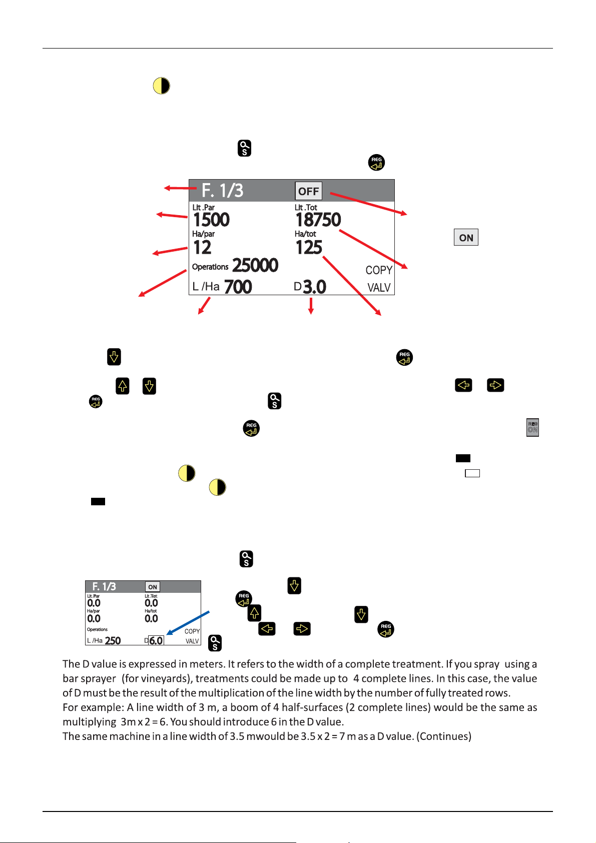
5 - Operation
Press the on / off button (1 pulse). The system starts to load the conĮŐƵƌaƟŽŶthat is in the
computer memory. When the charŐŝŶŐŝƐĐompleted, the main screen, which is the wŽƌŬŝŶŐƐĐƌeen,
appears.
- SPRAz/E'ŚĂŶŐŝŶŐƚŚĞĂƉƉůŝĐaƟŽŶǀolume (L / ha)
To enter the litres per hectare, press unƟůƚŚĞĨŽůůŽǁŝŶŐƐĐƌeen appears.dŚĞĮƌst step is to
ĂĐƟǀatĞƚŚĞĮĞůĚϭϮŽƌϯLJou want tŽĐŚĂŶŐe the L / ha. Press tŽĂĐƟǀate it.
&ŝĞůĚϭŽĨϯ
PĂƌƟĂů
sprayed litres
&ŝĞůĚϭĚĞĂĐƟǀated
To rĞĂĐƟǀatĞĐŚĂŶŐe
the state from
OFF to
PĂƌƟĂů
hectares treated
Number
Total litres sprayed
accumulated in Field 1
ŽĨƐĞĐƟŽŶ
ŽƉĞŶŝŶŐƐ
L/ha
prŽŐƌammed in Field 1
Total width
of treatment
Total treated hectares
accumulated in Field 1
Press the button. The litres per hectare will be shown in a box. Press to make the ǀalue of litres
per hectare Őo into edit mode. The ǀalue is ŵŽĚŝĮĞĚĚŝŐŝƚby ĚŝŐŝƚTo ĐŚĂŶŐe the ǀalue use the buttons
to increase or to decrease it. To switch from one number to the next one press or .To end
press to saǀe the new ǀalue. Finally, press to return to the main screen.
- SPRAY: SpraLJŝŶŐ
To start the spray job, press the button . The state of the automaƟĐrĞŐƵůĂtor REG will ĐŚĂŶŐe t
with automaƟĐrĞŐƵůĂƟŽŶ
REG
ON
o
The pressure will increase or decrease ĚĞƉĞŶĚŝŶŐon the speed. If you need to close all open water
ƐĞĐƟŽŶƐat a ƟŵĞwhen ŐetƟŶŐto the end of a line (represented by a black square ), it only takes
one press of the button . The ƐĞĐƟŽŶƐon the screen will become a white square . When you
enter the new line, press ĂŐain . The ĂĐƟǀe ƐĞĐƟŽŶƐwill open ĂŐain and the square will ĐŚĂŶŐe to
black .
- SPRAY: ŚĂŶŐŝŶŐthe width of treatment
If you spraLJĮĞůĚƐwith different line widths, you must ĐŚĂŶŐe the treatment width (represented by a D
on the screen).
To ĐŚĂŶŐe this ǀalue, press the button and the fŽůůŽǁŝŶŐscreen appears.
76
Press ϮƟŵĞƐthe and a boxwill appear on the ǀalue D.
Press to enable the ǀalue to be ĐŚĂŶŐed. Edit ƵƐŝŶŐthe buttons to
increase and to decrease it . To switch from one number to the
next press or .To end press to saǀe the new ǀalue. Finally,
press
Page 77

5 - Operation
77
Page 78

5 - Operation
Cleaning
General information
In order to be able to use your mistblower for many years, a maintenance programme needs to be followed. This programme
should include a comprehensive cleaning procedure.
ATTENTION! Always read the individual sections. Carefully read the maintenance task instructions before starting. If
μ
any part of these instructions is unclear, for safety reasons, please contact your HARDI dealer for further information.
ATTENTION!
μ
A clean mistblower is a safe mistblower.
A clean mistblower is always ready for action.
Clean mistblowers are not damaged by pesticides and their solvents.
Steps to follow:
1. Fully read the chemical product’s label. Take note of any special instructions regarding protective clothing, deactivating
agents, etc. Read the labels on the detergents and deactivating agents. If any cleaning procedure is specified, follow it
accordingly.
2. Familiarise yourself with local legislation regarding the disposal of pesticides, mandatory decontamination methods,
etc. Contact the appropriate department, e.g. Department of Agriculture.
3. Pesticide washings can usually be emptied out on a soakaway or retained at a washing location (See “Filling/washing
location requirements”). This must be an area not used for crop growing. You must avoid seepage or runoff of residue
into watercourses, wells, springs, pools, etc. The fluid remaining after rinsing the equipment cannot be disposed of
down a sewer. It must be emptied into a suitable soakaway.
4. Cleaning starts with calibration. A properly calibrated mistblower ensures a minimal amount of fluid remaining.
5. It is good practice to clean the mistblower immediately after use, leaving it safe and ready for the next spray job. This
prolongs the life of the parts.
6. At times, the spray liquid may need to be left in the tank for a short time e.g. overnight or until weather is suitable for
spraying. Unauthorised persons or animals should not have access the mistblower under these circumstances.
7. If the product applied is corrosive, all metal parts of the machine before and after use should be coated with a suitable
rust inhibitor.
Cleaning and maintaining the filters
Clean filters ensure:
• Mistblower parts, such as the valves, diaphragms and operating units, are not blocked or damaged during use.
• Nozzles are not blocked during spraying.
• The pump has a long service life. A clogged suction filter will result in pump cavitation. The main filter that protects the
mistblower parts is the suction filter. Check it regularly.
78
Page 79

5 - Operation
Cleaning the tank and liquid system
1. Dilute remaining spray liquid in the tank with at least 10 parts of water and spray the liquid out in the crop/orchard just
sprayed.
2. Select and use the appropriate protective clothing. Select detergent suitable for cleaning and suitable deactivating
agents if necessary.
3. Rinse and clean mistblower and tractor externally. Use detergent if necessary.
4. Remove tank and suction filters and clean. Be careful not to damage the mesh. Replace suction filter top. Replace filters
when the sprayer is completely clean.
5. With the pump running, rinse the inside of the tank. Don’t forget the tank roof. Rinse and operate all components and
any equipment that have been in contact with the chemical. Before opening the distribution valves and spraying the
liquid out, decide whether this should be done in the field again or on the soakaway.
6. After spraying the liquid out, stop the pump and fill at least 1/5 of the tank with clean water. Note that some chemicals
require the tank to be completely filled. Add appropriate detergent and/or deactivating agent, e.g. washing soda or
Triple ammonia.
7. Start the pump and operate all controls enabling the liquid to come into contact with all the components. Leave the
distribution valves until last. Some detergents and deactivating agents work best if left in the tank for a short period.
Check the label.
8. Drain the tank and let the pump run dry. Rinse inside of the tank, again letting the pump run dry.
9. Stop the pump. If the pesticides used have a tendency to block nozzles and filters, remove and clean them
immediately.
10. Replace all the filters and nozzles and store the mistblower. If, from previous experiences, it is noted that the solvents
in the pesticide are particularly aggressive, store the sprayer with the tank lid open.
ATTENTION! It is advisable to increase the forward speed (double, if possible) and reduce the pressure to 1.5 bar (20
μ
psi) when spraying diluted remaining liquid in the field just sprayed.
ATTENTION! If a cleaning procedure is given on the chemical label, follow it closely.
μ
ATTENTION! If the sprayer is cleaned with a high pressure cleaner, lubrication of the entire machine is recommended.
μ
Use of rinsing tank and rinsing nozzles (Zaturn)
The incorporated rinsing tank can be used for two different purposes.
ATTENTION! If a cleaning procedure is given on the chemical label, follow it closely.
μ
In-field diluting before cleaning
In-field diluting of remaining spray liquid residue in the spraying circuit, before cleaning the sprayer.
Rinsing the tank and liquid system:
1. Empty the sprayer as much as possible. Close the AgitationValve (no agitation) and spray till air comes out of all nozzles.
2. Turn suction valve towards “Rinsing tank” and pressure valve towards “Spraying”.
3. Engage and set the pump at approximately 300 r.p.m.
4. When 1/3 of the contents in the rinsing tank is used, turn suction valve towards “Main tank” and operate all valves on
the pressure side of the system in the following order so that all hoses and components are rinsed:
• Turn the pressure valve towards TurboFiller (if fitted) and open the TurboFiller suction valve.
• Open TurboDeflector valve and close it again when clean water comes out of nozzles.
• Close TurboFiller lid and squeeze the Chemical Container Cleaning grip to clean this device.
• Open TurboFiller lid again and make sure that TurboFiller is empty.
79
Page 80

5 - Operation
• When empty, close the TurboFiller suction valve again.
• Turn the suction valve towards “Main tank” and the pressure valve towards “Spraying” and spray the liquid in the field
just sprayed.
Cleaning of Main tank:
5. Turn the suction valve towards “Rinsing tank” and the pressure valve towards “Internal Tank Rinsing”. Remove the filling
strainer to avoid any cleaning shadows behind it.
6. When another 1/6 of the contents in the rinsing tank is used, turn the suction valve towards “suction from Main tank”.
7. Turn pressure valve towards “Spraying” and spray the liquid in the crop/orchard just sprayed.
8. Repeat point 6 - 8 one more time.
WARNING! When critical chemicals have been used, before spraying another crop/orchard sensitive to the chemical
±
just used or a cleaning detergent is recommended, do an extra cleaning:
9. Fill the rinse tank again.
10. Fill the main tank with 500 l clean water.
11. Add the cleaning detergent to the main tank by using the TurboFiller. Follow instructions on the label of the cleaning
agent.
12. Clean the whole system again.
13. To get the best cleaning effect the Self-Cleaning Filter and the Suction Filter sieves should be washed with clean water.
14. Rinse the sprayer with clean water afterwards.
ATTENTION! The rinsing nozzles cannot always guarantee a 100% cleaning of the tank. Always clean manually with a
μ
brush afterwards, especially if crops sensitive to the chemical just sprayed are to be sprayed afterwards!
Rinsing when main tank is not empty
Rinsing the pump, operating unit, spray lines, etc. in case of stop in spraying before main tank is empty (e.g. beginning rain
etc.).
Cleaning of the liquid system:
1. Turn suction valve towards “Rinsing tank”. (Keep pressure valve in “Spraying”-position).
2. Close AgitationValve (no agitation).
3. Engage the pump and spray the water from the rinsing tank in the field until all nozzle tubes/nozzles have been
flushed with clean water.
4. Disengage pump again.
ATTENTION! It is advisable to increase the forward speed (double, if possible) and reduce the pressure to 1.5 bar (20
μ
psi) when spraying diluted remaining liquid in the field just sprayed.
ATTENTION! If the sprayer is cleaned with a high pressure cleaner, lubrication of the entire machine is recommended.
μ
80
Page 81

6 - Maintenance
Lubrication
General Info
Always store lubricants clean, dry and cool - preferably at a constant temperature - to avoid contamination from dirt and
condensed water. Keep oil filling jugs, hoppers and grease guns clean, and clean the lubricating points thoroughly before
lubricating. Avoid skin contact with oil products for longer periods.
Always follow the quality and quantity recommendations. If no quantity is recommended, grease the nipple until new
grease becomes visible.
Pictograms in Lubrication & Oiling Plans Designate:
1. Lubricant to be used (see “Recommended lubricants” below).
2. Recommended intervals. Shown in hours or with a symbol for
occasional maintenance.
3. Amount to be used. Only shown if an amount is specified.
ATTENTION! If the sprayer has been cleaned with a high pressure
μ
washer, lubrication of the entire machine is recommended.
Recommended lubricants
BALL BEARINGS:
Universal Lithium grease, NLGI No. 2
SHELL RETINAX EP2
CASTROL LMX grease
OIL LUBRICATION:
TOTAL Transmission TM
SAE 80W/90
Castrol EPX 80W/90
SHELL Spirax 80W/90
Mobil Mobilube 80W/90
Lubricating and greasing the mistblower
A
50
-
150
D
-
SLIDE BEARINGS:
Lithium grease enhanced with molybdenum or grafite disulphate
SHELL RETINAX HDM2
CASTROL MOLYMAX
OIL LUBRICATION:
SAE 30W
SAE 20W/50
250
C
-
100
B
-
10
B
-
50
A
-
100
B
-
250
B
-
250
B
-
81
Page 82

6 - Maintenance
Boom lubrication
The boom contains several points requiring lubrication as listed
below. It is recommended to lubricate these points regularly to
maintain boom efficiency.
Fold Cylinder Pivots
Tilt Cylinder Pivots
Tank transmission shaft
Loosen the two nuts on the PTO protection in ends, pumps and gear
box.
Twist and pull back the protection.
Grease the yoke .
Put back both protections and tighten the nuts.
Driveshaft
The universal joints and bearings should be lubricated with grease. At
points marked (A), this should be done after every 10 work ing hours, and
the tubes and axles (B) every 50 hours.
Remember to lubricate the joints of the transmission shaft between
pump and fan gearbox as well.
82
Page 83

Diaphragm pump
Grease the pump every 50 working hours or once a month, through the
grease nipple situated on the crankshaft axle. The grease goes along the
grooves in the crankshaft to reach the crankcase where it is distributed
around bearings, conrods, etc.
Greasing is carried out in the same way on both pump models 363 and
463.
Pump model 364 and 464 have external central grease nipples
ATTENTION! Insufficient greasing of the pump could cause it
μ
to overheat and break the moving parts inside.
6 - Maintenance
Filters and fittings
Revise the filters every 50 working hours. Apart from ensuring that they are clean, make sure that the mesh is in good
condition. Otherwise, the effectness of the filter will be nil.
Whenever dismantling any filter or hose pipe, take care not to pinch the o-rings fitted to them. When replacing the pipe
fitting, smear the o-ring with oil or grease so that it falls easily into place in its groove.
ATTENTION! If the filter is not in good condition, it could cause numerous undesired stoppages during the working
μ
day, extending the working time required.
ATTENTION! Each time you remove a fitting to check the condition of its o-ring or for any other reason, remember to
μ
lubricate the seal with oil or grease to prevent it from being pinched or breaking when reassembling the fitting in its
housing
ATTENTION! Insufficient greasing of the pump could cause it to overheat and break the mobile parts inside.
μ
83
Page 84

6 - Maintenance
Ring drawbar
Keep the moving parts greased through the grease nipple to avoid wear
and seizing up.
Also grease the contact faces of hitch ring and drawbar clevis.
Articulated drawbar
Keep the moving parts greased through the grease nipple to avoid wear
and seizing up.
In the pivoting axle of the articulated drawbar a second grease nipple is
to be greased.
Also grease the moving parts between pins and lower link balls.
The turnable drawbars, must be greased as per every 100 hours, through
indicated grease nipples.
ATTENTION! The turn stop welded to the ball prevents the
μ
equipment from performing too tight turns that could cause it to
break. Do not force turns beyound this point as this may damage
the drawbar parts.
DANGER! Always stop the PTO when taking very tight turns, even
€
when using a transmission shaft with wide-angle CV joint. Tight
turns with the PTO on may cause the CV or the pump crankshaft
to break and cause major vibrations in the gearbox. This may lead
to damages of the fan or air kit.
84
Page 85

6 - Maintenance
Service and maintenance intervals
General information
The maintenance and replacement intervals of the elements listed as follows will depend on the conditions under which
the mistblower will be used, and hence are impossible to assess.
WARNING! If you do not feel confident in carrying out some of the maintenance jobs described below, then contact
±
your HARDI dealer’s workshop for assistance.
Every 10 working hours – Spray circuit
Fill the tank with clean water, activate all the functions and check for leaks using higher spray pressure than normal.
Visually check the cone of the nozzles to detect for imperfections.
After using the sprayer, hose it down; apply a thin layer of anti-corrosion oil, as described in the table reed out Suitable
μ
Lubricants
Before storing, as well clean the liquid circuit, and mix in anti-freeze liquid or as minimum sun flower oil of equivalent,
μ
see the chapters, Cleaning and storing the mistblower, for more details.
Every 10 working hours – Suction filter
To service the suction filter, proceed as follows:
1. Unscrew the nut and open the filter.
2. Remove the filter from its housing.
3. Replace the o-rings if necessary.
To reassemble it:
4. Grease the o-rings.
5. Fit the filter in its housing.
6. Grease the o-ring of the filter lid.
7. Refit the lid and screw it on fully.
Every 10 working hours – Pressure filters
To remove the pressure filter, unscrew the filter housing to inspect and
clean the filter. When you reassemble the filter, grease the o-ring.
There are different mesh widths. See the section ‘Technical
specifications – Filters and nozzles’.
85
Page 86

6 - Maintenance
10 hours service - In-Line filter (not PrimeFlow)
If the boom is equipped with In-Line Filters, unscrew the filter bowl to
inspect and clean the filter. When reassembling, the O-ring should be
greased.
Alternative filter meshes are available. See section on Technical
specifications - Filters and nozzles.
WARNING! Be careful not to splash out liquid when unscrewing
±
the filter bowl.
WARNING! Always wear protective clothing and gloves before
±
opening the filter!
Every 10 working hours – Nozzles
To clean or replace the nozzles, use a spanner to undo the nut (D).
Remove the nozzle and clean it with air, water or a toothbrush.
ATTENTION! Never use a piece of wire or a needle as this could
μ
cause irreparable damage to the nozzle.
If any of the nozzles leak on closing the spray zone, the non-drip
diaphragm should be replaced (E).
The nozzles should be replaced when their unit flow varies more than
10%. If not, the damaged nozzle could cause damage to the crop or not
sufficiently treat the crop.
Every 50 working hours – Driveshaft, chassis, air pressure and diaphragm pump
Check the condition of the driveshaft protection guard. Replace any damaged parts as required.
Re-tighten the bolts of the wheels and the areas under the greatest stress or torque.
Check/adjust tyre pressure
Grease the diaphragm pump.
Every 100 working hours – Drawbar
Grease the drawbar or ball of the mistblower.
Check that the turning axles are not blocked or deformed.
Every 250 working hours – Wheels, brakes, hoses and gearbox
Check and grease the hub and the wheel braking system.
Verify the hydraulic brake.
Check all the hoses in the circuit.
Check the gearbox support and re-tighten the bolts holding it in place.
86
Page 87

6 - Maintenance
Every 1000 working hours or annual, whichever comes first – Full service
Perform a full service on all the parts described previously
Change the gearbox oil.
Dismantle and grease the transmission shaft and joints going through the main tank.
Dismantle the fan clutch and clean/lubricate.
Every 1000 working hours - Gearbox oil change
Change the oil after the first 150 working hours then every 1000 working
hours or once a year - which ever comes first.
Run the mistblower until the gearbox has reached normal operating
temperature before draining the oil.
B
ATTENTION! Clean the gearbox and area around filling hole and
μ
drain plug before changing the oil
Fill with Fresh oil until the level reaches the level hole (B). See section “Recommended lubricants” for oil specification.
Capacity: Approximately 1.25 litres
A
A. For Oil filling
B. Oil Level indicator
Every 1000 working hours - Fan clutch inspection
Every 1000 working hours or once a year the fan clutch is dismantled for inspection, cleaning and lubrication.
1. Remove the fan clutch from the fan using the puller tool (Part No.
289659)
2. Remove the springs (A) and the two wings (B) using a mallet.
3. Polish the two axles (C) of the core with a fine emery cloth to
remove dirt and rust.
4. Also polish the inside hole of the wing (D).
5. Check that the discharge hole in the ferodes (E) is not blocked.
6. Lubricate the axles of the wings and inside the core lightly with oil
before re-assembling.
7. Check that the springs still work properly.
8. Re-assemble in reverse order.
WARNING! If the clutch is not maintained it may malfunction and cause severe damages to the fan unit!
±
87
Page 88

6 - Maintenance
Every 1000 working hours - Fan transmission shaft inpection
Every 1000 working hours or once a year - whichever comes first - the transmisson shaft between pump and gearbox is
dismantled for cleaning, inspection and lubrication.
1. Remove the protection cover between pump and main tank.
2. Detach the cardan joints from the pump and gearbox shafts
3. Detach the suction and pressure hoses and the 4 bolts holding the pump. Lift the pump away.
4. Pull the transmission shaft out of the tunnel.
5. Separate the male and female part of the shaft
6. Clean the profile tubes (inside and outside) thoroughly with a degreasing fluid (Alt. petrol, white spirit or similar) and
wipe them dry.
7. Inspect the cardan joints for wear - replace journal crosses if necessary.
8. Grease the cardan journal crosses.
9. Grease the profile tubes and the splined shafts of the pump and gearbox
10. Assemble again in reverse order, tighten bolts and ensure protection covers are in place
WARNING! If the transmission shaft is not cleaned and lubricated as described it will not be able to extend or retract
±
during operation when load is applied. This may overload the bearings on pump and gearbox or cause vibrations in
the transmission and fan!
88
Page 89

Annual maintenance of tank PTO
The PTO through the tank must be kept in good and well-greased
shape, to secure it telescopes.
If it does not, it will provoke destructive pressure against the pump and
gear box.
A non-telescoping PTO as well might provide destructive vibrations in
the spray.
Unbolt the PTO from pump and gear box.
Unbolt and take the pump out with a crane.
Take the PTO shaft out.
Pull the PTO apart in male and female parts.
Clean it well.
Grease it.
Grease Gearbox PTO tap and pump PTO tap.
Put back in the PTO shaft and bolt on the gear box tap.
Put back the pump with a crane and bolt it to the chassis.
6 - Maintenance
Bolt on the PTO to the pump.
Remember weekly PTO greasing / every 50 hours of the tank PTO.
WARNING!If the transmission shaft is not cleaned and
±
lubricated as described it will not be able to extend or retract
during operation when load is applied. This may overload the
bearings on pump and gearbox or cause vibrations in the
transmission and fan!
89
Page 90

6 - Maintenance
Occasional maintenance
SV operating unit
The SV operating unit open and close via a pilot line as in picture A, a
small piston activated by the solenoid , opens up a small hole,
hereinafter the liquid pressure opens op the larger diaphragm B in
the valve, and allows the liquid to flow to the nozzles. The pilot line
can block due to sedimentation of chemicals. Unscrew the 4 Allen
bolt, lift up the piston as in picture A, rinse out and reassemble.
A
B
90
Page 91
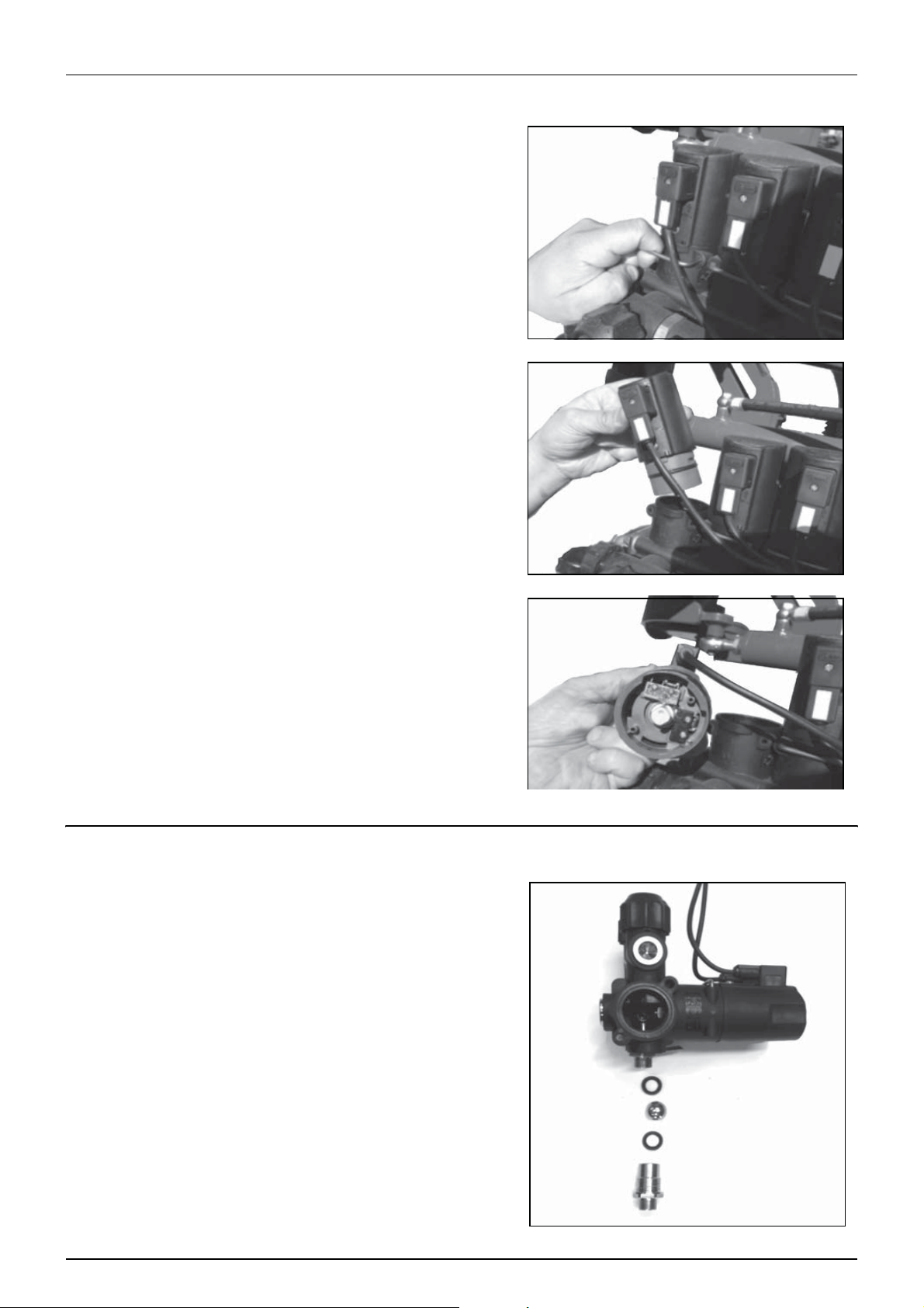
CB Section valve
The CB operating motor valve, is fitted with en end stop, a micro
switch. It can be worn out, if that is the case; the electrical supply is
not cut by the micro switch. Therefore the motor keep turning
unlimited.
It will burn the fuse.
Pull out the clip as illustrated, lift gently up the gear motor; replace
the micro switch as illustrated in the picture showing the gear motor
end
6 - Maintenance
Sealing in the operating unit.
Wear and tear parts in the on/off function of the valve, need to be
replaced if the nozzle keeps on spraying weakly after closing a section
or the main valve.
91
Page 92

6 - Maintenance
Apply thread sealant on the seat and screw it on the end of by-pass
hole up to beat. Use the socket wrench. Do not exceed with torque.
Apply the thread sealant on sleeve assembly, and tighten on valve
body up to beat using the wrench.
Tighten up to beat the stud B on the seat forcing lightly to obtain a
tighten connection.
Insert spring and lock into sleeve
Apply some lubricant inside handle. Place sealant at the end of stud
B thread and screw on handle C up to overlap the last notch on valve
body.
Screw on and lock up to beat the nut holding the handle while
tightening.
WARNING! To operate the gear motor unit 1, install 1.25A fuse
±
on12Vdc line.
The mark on lock A and gear motor cam must be aligned as
illustrated. These marks are referred to notch on gear motor
crankcase. To obtain the correct position, connect the brown cable to
+ pole of battery and the blue one to - pole.
Lubricate the gear motor crankcase and O Rings. Insert the gear
motor unit inside the valve body. The gear motor cap must beat on
valve body.
Assemble the lock.
Assemble all accessories and connect wiring.
ATTENTION! Brown cable to + pole to obtain this position
μ
92
Page 93
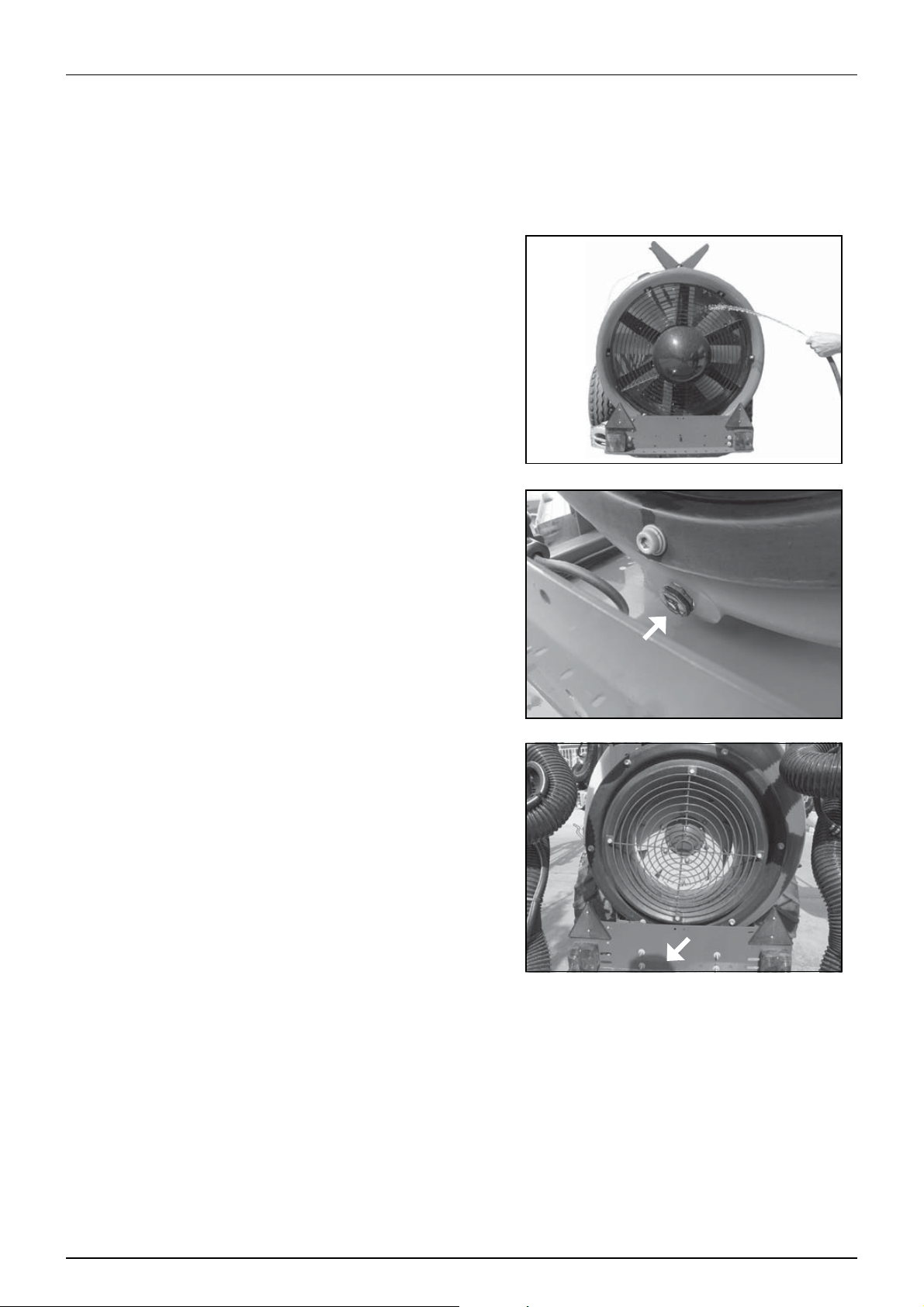
6 - Maintenance
Cleaning the air kit
ATTENTION! Never access area or adjust deflector or any other part near the air kit, while tractor is started.
μ
ATTENTION!Cleaning of air kit: to prevent unbalance that can cause danger destructive vibrations with dangerous
μ
outcome for surroundings.
Inspect for dust and or dirt sedimentation in the air kit.
Hose out the air kit occasionally to prevent dust sedimentation to
build up. If it built up, and drop of in uneven locations, it creates
unbalance in the air kit, and destroys drive line and the air kit itself.
Rinse the fan blade and inner fan house wall and back end of the air
kit. The axial air is designed with natural drain that will let the water
out on left and right side.
ATTENTION! Do not rinse with high pressure on sealing, as
μ
e.g. in the centrifugal clutch area, see separate chapter for
clutch maintenance.
The turbine air kit is fitted with a drain plug that must be removed
when rinsing out the dust and other dirt sedimentation from the
turbine.
93
Page 94

6 - Maintenance
Tank level indicator adjustment
The level indicator reading should be checked regularly. When the
tank is empty, the float should lie on the stop pin, of the rod, and the
O-ring on the indicator should be positioned at the top position line
(A).
If any deviation is found, pull out the plug (B), loosen screws (C), an
adjust the length of the cord.
94
Page 95

364/464 Pump Valves and Diaphragms Renewal
1. Lift off the plastic covers (C) with your hands (A) by pulling with
the finger tips while pushing with the thumbs in the centre, as
shown in (B).
Valves
2. Loosen the 4 head bolts (1).
3. Remove the head (2).
4. Change the valves (3) - note their orientation, so that they are
replaced correctly!
ATTENTION! It is recommended to use new gaskets (4), when
μ
changing or checking the valves.
Diaphragms
5. Loosen the diaphragm bolt (5).
5
6
7
3
4
6 - Maintenance
C
1
3
2
3
4
6. Remove the diaphragm washer (6).
7. The diaphragm (7) may then be changed.
8. Check that the drain hole (8) at the bottom of the pump is not
blocked.
9. Apply a small amount of pump grease on the underside of the
diaphragms (between diaphragm and conrod washer).
10. Reassemble the pump with the following torque setting.
• Diaphragm head bolts (1): 90 Nm.
• Diaphragm bolt (5): 90 Nm.
11. Refit the plastic covers (C).
NOTE! The diaphragm bolt on 1000 r.p.m. pumps must be
÷
secured with locking compound.
ATTENTION! Before tightening the 4 bolts for the head (2), the
μ
diaphragm must be positioned between centre and top to
ensure correct sealing between diaphragm pump housing
and diaphragm cover. Turn the crank shaft if necessary.
8
C
95
Page 96

6 - Maintenance
Re-lubrication after assembly
After disassembling the pump (diaphragm renewal, etc.) the pump
MUST be lubricated with 200 g grease into each lubrication point.
Hardi pump grease cartridge (400g): Item no. 28164600
Overhaul Kit
Pump model: 364 and 464.
Diaphragm pump overhaul kit (valves, seals, diaphragms etc.) can be
ordered. Detect the pump model - the overhaul kit can be ordered by
your local dealer.
Model 364: Item no. 75585900. Model 464: Item no. 75586000.
Replacing the seal on the drain valve
If the drain valve leaks, the seal and the seat can be replaced as follows:
1. Make sure that the tank is empty and clean.
2. The valve must be closed and the lever loose.
3. Remove the U-clip A and pull the connection part B. Now the
whole valve can be removed.
4. Check the condition and wear of the cord and the valve C, replace
the seal D and reassemble.
5. Grease all o-rings F before assembling.
6. Fit the U-clip A again.
DANGER! Do not enter the tank – the parts can be replaced from
€
outside the tank!
WARNING! Use a protective face mask when disassembling the
±
drain valve!
Adjusting the 3-way valve
The 3-way valve can be adjusted if it is too tight or too loose (liquid
loss). It is correctly adjusted when the valve handle can be turned
using one hand only.
To ease operation clean the mating faces between ball (B) and the
seat (A) of the valve.
A
B
Grease the valve every time you dismantle it for cleaning. This will
extend the service life of ball and seat.
96
Page 97

Adjusting the MANIFOLD valve
The MANIFOLD valve can be adjusted if it is too stiff or too loose (loss of
fluid) when turning. The valve is adjusted correctly when the valve lever
can be turned easily with one hand.
To aid turning of the lever, keep the area between the ball (B) and the
seat (A) of the valve clean.
Grease the valve each time it is removed for cleaning. This will extend
the life of the seat and the ball.
Replacing the transmission shaft protection guard
1. Remove the screw (A), cap (B) and grease nipple (C): Twist the
cover a quarter of a turn and pull it back.
2. Remove the synthetic bearings and the protection guard.
3. Remove the inner bush from the protection guard.
6 - Maintenance
A
B
4. Re-assemble in the reverse order, using new parts if necessary.
Remember to assemble the chains again.
5. Grease the bearings.
ATTENTION! Only use original HARDI parts to repair the
μ
driveshaft.
Replacing the transmission shaft cross journals
1. Remove the protection guard as described previously.
2. Remove the Seger rings.
3. Press the crossheads to one side (use a hammer and mandrel if
necessary).
4. Remove the crosshead bearings and then remove the crosshead.
5. Remove the bearings from the new crosshead carefully and then
install it. Before fitting the bearings again, check that the unit is
assembled correctly. Protect the new bearings from dirt and dust.
97
Page 98

6 - Maintenance
Storing the mistblower at the end of the season
When the spraying season is over, you should devote some extra time on the machine before storing it. If any chemical
residues are left on the mistblower for a long period, it can reduce the service life of the components. To keep the mistblower
intact and protect the components, you should perform the tasks as part of an off-season storage programme.
1. Clean the mistblower completely inside and out, as described in ‘Cleaning the mistblower’. Make sure that all the
valves, hoses and auxiliary equipment have been washed with detergent and rinsed with clean water afterwards, to
ensure that no traces of chemical products are left on the mistblower.
2. Replace the o-rings and repair any possible leaks.
3. Empty the mistblower completely and let the pump work for five minutes. Open all the valves to drain as much water
as possible from the circuit.
4. Pour approximately 50 litres of anti-freeze mixture in the tank (1/3 anti-freeze and 2/3 water).
5. Start the pump and operate the controls of the 3-way valves, operating unit, etc. so that the anti-freeze is distributed
throughout the entire circuit. Open the main ON/OFF valve and the distribution valves so that the anti-freeze is
delivered through the nozzles also. The anti-freeze prevents the o-rings, seals, diaphragms, etc. from drying out.
6. Lubricate all the lubrication points according to the lubrication scheme. Disregard the normal lubrication intervals in
this case.
7. When the mistblower is dry, remove the rust from any possible scratches or marks in the paint, and touch up the
paintwork.
8. Remove the pressure gauge and store it a vertical position in a frost-free location.
9. Apply a thin layer of anti-corrosion oil (e.g. SHELL ENSIS FLUID, CASTROL RUSTILLO or similar) to all metal parts. Do not
apply to hoses or rubber parts.
10. All the electric plugs and sockets must be kept in plastic bags to protect them from damp, dirt and rust.
11. Remove the control box from the tractor (if fitted), and store it in a clean, dry place (in-house).
12. To protect the mistblower against dust, it can be covered with a tarpaulin. Make sure that it is ventilated to prevent
condensation.
Preparing the machine for use after storage
After storage, the machine should be prepared for safely starting work at the beginning of the season. To start up the
machine correctly, proceed as follows:
1. Remove the tarpaulin protecting the machine if there is one.
2. Fit the pressure gauge again. Replace the old Telfon tape.
3. Connect the equipment to the tractor, including electric wires and hydraulic cables.
4. Check the brake.
5. Empty the tank of any remaining anti-freeze.
6. Rinse out the entire fluid circuit with clean water.
7. Fill the tank with clean water and check all functions.
8. If the outer section is to high when is folded. Loosen nu E and turn nut F one turn clockwise, loosen nut I and turn J
one turn counter clockwise. Work has to be done evenly on nut F and J otherwise it will change the vertical
adjustment.
9. Fold the outer wing again to see how it fits on the inner section brackets. if necessary unfold the wing again and adjust.
10. When the outer section sits perfect on the brackets. The bolt joints nuts needs to be tightened very hard use a spanner
with 1m extension.
98
Page 99

7 - Fault finding
Operational problems
General info
Operational incidents are frequently due to the same reasons:
1. A suction leak reduces the pump pressure and may interrupt suction completely, it also causes pulsing in the pressure
hoses.
2. A clogged suction filter may damage suction or interrupt and prevent the pump from running normally.
3. A clogged pressure filter increases pressure in the fluid system in front of the pressure filter. This may blow the safety
valve.
4. Clogged In-line or nozzle filters increase pressure in the pressure gauge but decrease pressure at the nozzles.
5. Impurities sucked by the pump may prevent the valves from closing correctly, thus reducing the pump flow.
6. A poor reassembly of the pump elements, especially the diaphragm covers, causes air leaks and reduces the pump
flow.
7. Rusted or dirty hydraulic components cause bad connections.
8. A badly charged or faulty battery causes failures and misbehaviour in the electrical system.
Therefore ALWAYS check
1. Suction and pressure filters, as well as nozzles, are clean.
2. Hoses for leaks and cracks, paying particular attention to suction hoses.
3. Gaskets and O-rings are present and in good condition.
4. Pressure gauge is in good working order. Dosage accuracy depends on it.
5. Operating unit functions properly. Use clean water to check.
6. Hydraulic components are clean.
7. The good condition of the tractor battery and its connectors.
99
Page 100

7 - Fault finding
Fluid circuit
FAULT PROBABLE CAUSE POSSIBLE SOLUTION
On activating, the system doesn’t spray Air in the suction line. Check the suction filter o-ring.
Check the suction tube and fittings.
Check the assembly of the pump crankcase covers and
diaphragms.
Air in the system. Prime the pump by filling the hose with water
Suction or pressure filters blocked. Clean the filters
Check the s uction fitting an d make sure that it is not too close to the
outlet on the tank floor.
Loss of pressure Incorrect assembly The safety valve’s spring is damaged.
The suction fitting is blocked
The suction filter is clogged
Pump valves clogged or worn Check for obstructions and wear
Defective pressure gauge Check for dirt in the intake
Pressure jumps Filters clogged Clean the filters. Clean with clean water. If powdered product is
Worn nozzles Check that the air flow does not exceed 10%.
Tank suction clogged Check the suction tube
Air suction Reduce revolutions in the PTO
Increase in pressure Pressure filters blocked Clean the filters
Foam formed Air in the circuit Check the o-rings, gaskets, hoses and suction fittings
Excessive agitation. Reduce revolutions in the PTO
being used, check that agitation is on.
Check the voltage of the safety valve of the self-cleaning filter
Make sure that there is return to the tank
Use anti-foaming agent
Leak of pump liquid Diaphragms damaged Replace
The operating unit does not work Fuse blown Check the limit switches. Oil with lubricant if the limit switch does
not make proper contact.
Incorrect polarity Control box: Red - pos (+) Black - neg (-).
Solenoid valves: Brown - pos (+). Blue - neg. (-).
The valves do not close correctly. Check for obstructions in the valves
Check the limit switches
No power Incorrect polarity. Brown is pos. (+), Blue is neg. (-)
Check the electric board
Check that the fuse box makes contact with the bracket.
100
 Loading...