


MEGA
VPZ
Original
Instruction book
67050600-110, version 1.10
GB - 03.2018
www.hardi-international.com

We congratulate you for choosing a HARDI plant protection product. The reliability and
efficiency of this product depend upon your care.
The first step is to carefully read and pay attention to this Instruction Book. It contains essential
information for the efficient use and long life of this quality product.
Sprayer Use
The HARDI sprayer is for the application of crop protection chemicals and liquid fertilizers, and it is designed only
for that purpose.
If the sprayer is to be used for any other purposes than the ones described in this Instruction Book, a new risk
assessment and a workplace assessment must be completed for this use. This obligation lies with the owner and
operator of the sprayer.
Your HARDI sprayer is a machine [A] without drive system in accordance with directive 2006/42/EC, article 2.
It must be connected to a tractor [B], which is a driving machine subject to its own directive.
Together they make one machine [C] as defined in the directive 2006/42/EC, article 2.
Connecting the sprayer to the tractor makes the operator responsible for safety and health when using that
combination of machines.
Before first use of the sprayer, the owner and operator must take note of all of the following obligations:
Workplace assessment
Operator instructions
Use of work equipment
Statutory inspection
Restricted use
Maintenance regulations
Health issues
For more details, please see “Before First Use of the Sprayer” on page 11 in this Instruction Book.
Instruction Book Formalities
The original Instruction Book is approved and published in English. All other languages are translations of the
original Book. In the event of any conflicts, inaccuracies or deviations between the English Book and other
languages, the English version shall prevail.
Illustrations, technical information and data in this Book are assumed to be correct at the time of printing.
As this Instruction Book covers more models and features or equipment, which are available in certain countries
only, please pay attention to paragraphs dealing with precisely your model.

EU Declaration of Conformity
As manufacturer:
HARDI INTERNATIONAL A/S
Herthadalvej 10
4840 Nørre Alslev
DENMARK
hereby declare that the following product
1 - EU Declaration
Field sprayer:
Identification number*:
* Further data for this sprayer are shown on its type sign.
fulfils all the relevant provisions of the following Directives of the European Parliament and of the Council:
• 2006/42/EC, regarding the Machinery Directive (CE marking).
• 2009/127/EC and later amendments, regarding machinery for pesticide application.
• 2014/30/EU, regarding electromagnetic compatibility (EMC). Electronic components on the machine are tested and
installed according to the requirements of the EMC Directive.
as well as the following ISO standard:
• ISO 14982, regarding test methods and acceptance criteria for electromagnetic compatibility for agricultural
machinery.
HARDI INTERNATIONAL A/S
Nørre Alslev, Denmark
Date:
Signature:
Name:
Job title:
3

1 - EU Declaration
4

Table of Contents
Table of Contents
1 - EU Declaration
EU Declaration of Conformity ................................................................................................................3
2 - Safety Notes
Obligations and Liability .....................................................................................................................11
Comply with the Instruction Book ........................................................................................................................................................... 11
Before First Use of the Sprayer .................................................................................................................................................................... 11
Obligations of the Operator ......................................................................................................................................................................... 14
Risks in Handling the Sprayer ...................................................................................................................................................................... 15
Disclaimer ................................................................................................................................................................................................................ 15
Organizational Measures ....................................................................................................................16
Personal Protective Equipment ................................................................................................................................................................. 16
Representation of Safety Symbols ......................................................................................................17
Explanation of Symbols ................................................................................................................................................................................... 17
Warning Signs On The Sprayer ............................................................................................................18
Explanation of Labels ........................................................................................................................................................................................ 18
Safety and Protection Equipment .......................................................................................................20
Safety at Start-up ................................................................................................................................................................................................. 20
Faulty Safety Equipment ................................................................................................................................................................................ 20
Informal Safety Measures ....................................................................................................................21
Additional Safety Instructions ..................................................................................................................................................................... 21
Operator Training ................................................................................................................................22
Authorized Persons ............................................................................................................................................................................................ 22
Safety Measures in Normal Operation ................................................................................................23
Protection Equipment ..................................................................................................................................................................................... 23
Residual Energy ...................................................................................................................................24
Possible Dangers ................................................................................................................................................................................................. 24
Service and Maintenance Work ...........................................................................................................25
Statutory Inspection .......................................................................................................................................................................................... 25
Preventive Measures ...........................................................................................................
Design Changes ...................................................................................................................................26
Operator Limitations ......................................................................................................................................................................................... 26
Spare Parts, Wear Parts and Aids ............................................................................................................................................................... 26
Cleaning and Disposal .........................................................................................................................27
Environmental Protection ............................................................................................................................................................................. 27
Workstation .........................................................................................................................................28
Intended Place for Operator ........................................................................................................................................................................ 28
Risks of Non-Compliance ............................................................................................................................................................................... 28
If the Safety Information is Ignored ....................................................................................................29
Possible Risks and Dangers ........................................................................................................................................................................... 29
Safety Information For Operators .......................................................................................................30
General Safety and Accident Prevention ............................................................................................................................................. 30
Coupling and Uncoupling the Sprayer ................................................................................................................................................. 31
Use of The Sprayer .............................................................................................................................................................................................. 32
Road Transport ..................................................................................................................................................................................................... 33
Hydraulic System ................................................................................................................................................................................................. 35
Electrical System .................................................................................................................................................................................................. 36
Universal Joint Shaft .......................................................................................................................................................................................... 37
Working Area of the Sprayer ........................................................................................................................................................................ 38
Field Sprayer Operation .................................................................................................................................................................................. 39
Environmental Precautions .......................................................................................................................................................................... 39
Service Work Precautions ............................................................................................................................................................................... 40
Cleaning .................................................................................................................................................................................................................... 40
Service and Maintenance .............................................................................................................................................................................. 41
.............................................................................. 25
5

Table of Contents
3 - Description
General info .........................................................................................................................................43
Overview .................................................................................................................................................................................................................. 43
Identification Plates ........................................................................................................................................................................................... 48
Sprayer Use ............................................................................................................................................................................................................. 50
Steel Frame ............................................................................................................................................................................................................. 50
Tanks ........................................................................................................................................................................................................................... 50
Lifetime ...................................................................................................................................................................................................................... 50
Liquid system ......................................................................................................................................51
Pump .......................................................................................................................................................................................................................... 51
Valves and Symbols ........................................................................................................................................................................................... 51
DynamicFluid4 Pressure Regulation ....................................................................................................................................................... 53
Filters ........................................................................................................................................................................................................................... 54
EasyClean Filter ..................................................................................................................................................................................................... 54
CycloneFilter .......................................................................................................................................................................................................... 55
TurboFiller ................................................................................................................................................................................................................ 56
RinseTank ................................................................................................................................................................................................................. 57
Clean Water Tank ................................................................................................................................................................................................ 57
Diagram - Basic Liquid System ................................................................................................................................................................... 58
Diagram - Liquid System with Options ................................................................................................................................................. 59
BoomPrime ............................................................................................................................................................................................................. 60
Dilution Kit ............................................................................................................................................................................................................... 61
Hydraulic System .................................................................................................................................62
Hydraulic Blocks ................................................................................................................................................................................................... 62
Open Centre Hydraulics .................................................................................................................................................................................. 62
Spray Boom .........................................................................................................................................63
Boom and Terminology .................................................................................................................................................................................. 63
Other Equipment .................................................................................................................................64
Nozzle Pressure Gauge .................................................................................................................................................................................... 64
Canister for Pesticide Information ............................................................................................................................................................ 64
Tank Level Indicator ........................................................................................................................................................................................... 65
External Cleaning Device ............................................................................................................................................................................... 66
Night Spraying Light ......................................................................................................................................................................................... 66
AutoSlant .................................................................................................................................................................................................................. 67
Ladder ........................................................................................................................................................................................................................ 67
4 - Sprayer Setup
General Info .........................................................................................................................................69
Unloading the Sprayer from the Truck .................................................................................................................................................. 69
Before Putting the Sprayer Into Operation ......................................................................................................................................... 69
Selection of Tractor ............................................................................................................................................................................................ 70
Applicable Tractors ............................................................................................................................................................................................ 70
Checking the Suitability of the Tractor ................................................................................................71
General Info ............................................................................................................................................................................................................ 71
Calculating Actual Weights and Loads .................................................................................................................................................. 71
Data Required for the Calculation ............................................................................................................................................................ 72
Required Minimum Front Weight ............................................................................................................................................................ 72
Actual Front Axle Load [T3] of the Tractor ........................................................................................................................................... 73
Actual Total Weight [W] of the Combined Tractor and Sprayer ............................................................................................ 73
Actual Rear Axle Load [T2] of the Tractor ............................................................................................................................................. 73
Calculation Compared to Permissible Values .................................................................................................................................... 73
Transmission Shaft ..............................................................................................................................74
Operator Safety .................................................................................................................................................................................................... 74
PTO Installation ..................................................................................................................................................................................................... 74
Mechanical Connections ......................................................................................................................75
Connecting the Sprayer .................................................................................................................................................................................. 75
6

Table of Contents
Hydraulic System .................................................................................................................................76
General Info ............................................................................................................................................................................................................ 76
Requirements for Tractor ............................................................................................................................................................................... 76
Open and Closed Centre Hydraulics ....................................................................................................................................................... 77
Adjustment of Boom Folding Speed ...................................................................................................................................................... 78
Electrical Connections .........................................................................................................................79
Power Supply ......................................................................................................................................................................................................... 79
Road Safety Kit ...................................................................................................................................................................................................... 79
Installation of Control Unit Brackets ........................................................................................................................................................ 80
Speed Transducer for Tractor ...................................................................................................................................................................... 80
Liquid System ......................................................................................................................................81
CycloneFilter .......................................................................................................................................................................................................... 81
BoomPrime Adjustment ................................................................................................................................................................................. 82
Spray Boom .........................................................................................................................................83
Adjustment of Suspension Effect .............................................................................................................................................................. 83
Anti-Yaw Mechanism ....................................................................................................................................................................................... 84
5 - Operation
General Info .........................................................................................................................................85
Environmental Info ............................................................................................................................................................................................ 85
Sprayer Use ............................................................................................................................................................................................................. 85
Symbols for Valves .............................................................................................................................................................................................. 86
Spray Boom .........................................................................................................................................87
Safety Info ................................................................................................................................................................................................................ 87
Operating the Grip ............................................................................................................................................................................................. 87
Maneuvering of the Boom ............................................................................................................................................................................ 88
Operating the Control Unit While Spraying ....................................................................................................................................... 90
Liquid System ......................................................................................................................................91
General Info ............................................................................................................................................................................................................ 91
Quick Reference - Operation ....................................................................................................................................................................... 91
Filling/Washing Location Requirements .............................................................................................................................................. 92
Filling of Water ...................................................................................................................................................................................................... 92
Filling Through Tank Lid ................................................................................................................................................................................. 93
External Filling Device ...................................................................................................................................................................................... 93
Filling of Rinsing Tank ....................................................................................................................................................................................... 94
Filling of Clean Water Tank ............................................................................................................................................................................ 95
External Filling Device ...................................................................................................................................................................................... 95
Safety Precautions - Crop Protection Chemicals ............................................................................................................................. 96
Operating the TurboFiller .............................................................................................................................................................................. 97
Filling Liquid Chemicals Using the TurboFiller ...............................................................................................................................100
Filling Powder Chemicals Using the TurboFiller ................................................................................
TurboFiller Rinsing ............................................................................................................................................................................................104
Agitation Before Resuming a Spray Job .............................................................................................................................................104
Dilution of Spray Liquid .................................................................................................................................................................................105
Before Returning to Refill the Sprayer ..................................................................................................................................................105
Parking the Sprayer ..........................................................................................................................................................................................105
BoomPrime ...........................................................................................................................................................................................................106
Liquid Fertilizer ...................................................................................................................................................................................................107
Additional Information ..................................................................................................................................................................................107
Operating Limits ................................................................................................................................................................................................108
Cleaning ............................................................................................................................................ 109
General Info ..........................................................................................................................................................................................................109
Quick Reference - Cleaning ........................................................................................................................................................................110
Standard Cleaning ............................................................................................................................................................................................111
Cleaning the Tank and Liquid System .................................................................................................................................................112
Cleaning and Maintenance of Filters ....................................................................................................................................................112
Use of Rinsing Tank and Rinsing Nozzles ...........................................................................................................................................113
Use of Cleaning Agent ...................................................................................................................................................................................114
Technical Residue .............................................................................................................................................................................................114
............................................102
7

Table of Contents
Full Internal Cleaning (Soak Wash) .........................................................................................................................................................115
Using the Drain Valve .....................................................................................................................................................................................116
Pressure Draining ..............................................................................................................................................................................................116
Outside Cleaning - Use of External Cleaning Devices ................................................................................................................117
6 - Maintenance
Lubrication ....................................................................................................................................... 119
General Info ..........................................................................................................................................................................................................119
Suitable Lubricants ...........................................................................................................................................................................................119
Grease Nipple ......................................................................................................................................................................................................120
Grease Gun Calibration .................................................................................................................................................................................120
Lubrication Plan - Boom Centre ...............................................................................................................................................................121
Lubrication Plan - Boom Wings ................................................................................................................................................................122
Lubrication and Oiling Plan - PTO ..........................................................................................................................................................123
Greasing the Pump ..........................................................................................................................................................................................123
Service and Maintenance Intervals .................................................................................................. 124
General Info ..........................................................................................................................................................................................................124
Periodic Inspection ..........................................................................................................................................................................................124
Tightening Bolts and Nuts ...........................................................................................................................................................................124
Tightening Hydraulic Hoses .......................................................................................................................................................................126
10 Hours Service - EasyClean Filter ........................................................................................................................................................127
10 Hours Service - CycloneFilter ..............................................................................................................................................................128
10 Hours Service - In-Line Filter ................................................................................................................................................................128
10 Hours Service - Nozzle Filters ..............................................................................................................................................................129
10 Hours Service - Spraying Circuit ........................................................................................................................................................129
50 Hours Service - Greasing the Pump ..........................................................................................
50 Hours Service - Transmission Shaft (PTO) ....................................................................................................................................130
250 Hours Service - Hydraulic Circuit ....................................................................................................................................................131
250 Hours Service - Hoses and Tubes ..................................................................................................................................................131
Occasional Maintenance ................................................................................................................... 132
General Info ..........................................................................................................................................................................................................132
Lifting and Removing the Pump .............................................................................................................................................................132
Pump Valves and Diaphragms Renewal .............................................................................................................................................133
Speed Transducer for Pump ......................................................................................................................................................................134
BoomPrime One-Way Valve .......................................................................................................................................................................135
Drain Valve Seal Replacement ..................................................................................................................................................................135
Adjustment of 3-Way Valve ........................................................................................................................................................................136
Safety Valve Activation ..................................................................................................................................................................................136
Feed Pipe Clamp Assembly ........................................................................................................................................................................137
Feed Pipe Snap-Lock Assembly ...............................................................................................................................................................137
Nozzle Pipe Assembly ....................................................................................................................................................................................138
Nozzle Holder Assembly ...............................................................................................................................................................................140
Change of Light Bulb ......................................................................................................................................................................................142
Replacement of Transmission Shaft Shield .......................................................................................................................................142
Replacement of Transmission Shaft Cross Journals ....................................................................................................................142
Readjustment of Boom - General Info .................................................................................................................................................143
Boom Adjustment Order ..............................................................................................................................................................................143
Trapeze Locking Device ........................................................................................................
Horizontal Alignment of Centre and Inner Sections ...................................................................................................................144
Horizontal Alignment of Inner and Outer Sections ..............................................................................
Vertical Alignment of Inner and Outer Sections ............................................................................................................................145
Over-Centre Boom Lock Adjustment ...................................................................................................................................................147
Boom Wings Forward .....................................................................................................................................................................................149
Boom Lift Adjustment ....................................................................................................................................................................................150
Glide Shoes - Yaw Damping .......................................................................................................................................................................151
Chassis Damping ...............................................................................................................................................................................................151
Venting the Boom Hydraulics ...................................................................................................................................................................152
........................................................................144
......................................................130
.......................................145
8

Table of Contents
Off-Season Storage ........................................................................................................................... 153
General Info ..........................................................................................................................................................................................................153
Before Storage ....................................................................................................................................................................................................153
After Storage ........................................................................................................................................................................................................154
7 - Fault Finding
Operational Problems ...................................................................................................................... 155
General Info ..........................................................................................................................................................................................................155
Liquid System ......................................................................................................................................................................................................156
Electric Fuses ........................................................................................................................................................................................................158
Overview of Fuses .............................................................................................................................................................................................159
Mechanical Problems ........................................................................................................................ 160
Emergency Operation - EasyClean Filter ............................................................................................................................................160
Emergency Operation - Liquid System ...............................................................................................................................................160
8 - Technical Specifications
Dimensions ....................................................................................................................................... 161
General Info ..........................................................................................................................................................................................................161
Overall Dimensions ..........................................................................................................................................................................................161
Weight .....................................................................................................................................................................................................................162
Pump Specifications ......................................................................................................................... 163
Pump Model 364/10.0 ...................................................................................................................................................................................163
Pump Model 464/10.0 ...................................................................................................................................................................................163
Pump Capacity ...................................................................................................................................................................................................163
Other Specifications ......................................................................................................................... 164
Tractor Requirements .....................................................................................................................................................................................164
Filters .........................................................................................................................................................................................................................165
Hydraulic Couplings .......................................................................................................................................................................................165
Transmission Shaft ............................................................................................................................................................................................166
Temperature and Pressure Ranges ........................................................................................................................................................166
Technical Residue .............................................................................................................................................................................................166
Airborne Noise Emission ...............................................................................................................................................................................166
Materials and Recycling .................................................................................................................... 167
Disposal of the Sprayer ..................................................................................................................................................................................167
Disposal of Cleaning Water .........................................................................................................................................................................167
Electrical Connections ...................................................................................................................... 168
Rear Lights .............................................................................................................................................................................................................168
Boom and Work Lights ..................................................................................................................................................................................169
Hydraulic Diagrams .......................................................................................................................... 170
Boom Hydraulics ...............................................................................................................................................................................................170
Index
Index ................................................................................................................................................. 173
9

Table of Contents
10

Obligations and Liability
2 - Safety Notes
Comply with the
Instruction Book
Knowledge of the basic safety information and safety regulations is a fundamental requirement for safe
handling and fault-free sprayer operation.
of k nowledge or non-compliance of the safety instructions can lead to injuries and fatal accidents as well
Lack
as damage to the sprayer and its surroundings.
Follow the safety instructions in this Instruction Book.
Before First Use of the Sprayer
The owner of the sprayer must take note of the following obligations before using the sprayer. These obligations also applies
to the employer or the supervisor of the sprayer operators.
Workplace Assessment
This must be completed to start with. Check your national regulations regarding
• the content of the workplace assessment
• the frequency of repeating the workplace assessment.
Worker / Operator Instructions
Only let those people work with, or on the sprayer, who
• are aware of the basic workplace safety information and accident prevention regulations
• have been instructed in working with/on the tractor and sprayer and hereby achieving appropriate qualifications
• have read and understood this Instruction Book.
If you still have queries after reading the Instruction Book, or if something remains unclear after reading it, please contact
the manufacturer or your HARDI dealer.
A worker is hereinafter called an operator. An operator is a person who installs, operates, configures, adjusts, maintains,
cleans, repairs, transports or moves the sprayer.
Use of Work Equipment
Throughout the lifetime of the sprayer, the owner shall take every measure to ensure the safety of the sprayer and its
equipment made available to operators according to European Directive 2009/104/EC – Use of Work Equipment.
Amendments to the directive, as well as subsequent directive versions are to be followed when applicable.
In this directive, the “minimum safety and health requirements for the use of work equipment by workers at work” are
described in full. To guide you in this matter, the issues concerning your work with the sprayer are listed below. However,
HARDI do not accept liability that the issues listed cover the requirements in the directive fully. This responsibility lies with
the owner of the sprayer.
From European Directive 2009/104/EC:
CHAPTER I
GENERAL PROVISIONS
Article 1
Subject matter
1. This Directive, which is the second individual directive within the meaning of Article 16(1) of Directive 89/391/EEC, lays
down minimum safety and health requirements for the use of work equipment by workers at work, as defined in Article
2.
2. The provisions of Directive 89/391/EEC are fully applicable to the whole scope referred to in paragraph 1, without
prejudice to more stringent or specific provisions contained in this Directive.
11

2 - Safety Notes
Article 2
Definitions
For the purposes of this Directive, the following terms shall have the following meanings:
(a) ‘work equipment’: any machine, apparatus, tool or installation used at work;
(b) ‘use of work equipment’: any activity involving work equipment such as starting or stopping the equipment, its
use, transport, repair, modification, maintenance and servicing, including, in particular, cleaning;
(c) ‘danger zone’: any zone within or around work equipment in which an exposed worker is subject to a risk to his
health or safety;
(d) ‘exposed worker’: any worker wholly or partially in a danger zone;
(e) ‘operator’: the worker or workers given the task of using work equipment.
CHAPTER II
EMPLOYER’S OBLIGATIONS
Article 3
General obligations
1. The employer shall take the measures necessary to ensure that the work equipment made available to workers in the
undertaking or establishment is suitable for the work to be carried out or properly adapted for that purpose and may
be used by workers without impairment to their safety or health.
In selecting the work equipment which he proposes to use, the employer shall pay attention to the specific working
conditions and characteristics and to the hazards which exist in the undertaking or establishment, in particular at the
workplace, for the safety and health of the workers, and any additional hazards posed by the use of the work
equipment in question.
2. Where it is not possible in this way fully to ensure that work equipment can be used by workers without risk to their
safety or health, the employer shall take appropriate measures to minimize the risks.
Article 5
Inspection of work equipment
1. The employer shall ensure that where the safety of work equipment depends on the installation conditions, it shall be
subject to an initial inspection (after installation and before first being put into service) and an inspection after
assembly at a new site or in a new location by competent persons within the meaning of national laws and/or
practices, to ensure that the work equipment has been installed correctly and is operating properly.
2. In order to ensure that health and safety conditions are maintained and that deterioration liable to result in dangerous
situations can be detected and remedied in good time, the employer shall ensure that work equipment exposed to
conditions causing such deterioration is subject to:
(a) periodic inspections and, where appropriate, testing by competent persons within the meaning of national laws
and/or practices;
(b) special inspections by competent persons within the meaning of national laws and/or practices each time that
exceptional circumstances which are liable to jeopardize the safety of the work equipment have occurred, such
as modification work, accidents, natural phenomena or prolonged periods of inactivity.
3. The results of inspections shall be recorded and kept at the disposal of the authorities concerned. They must be kept
for a suitable period of time.
When work equipment is used outside the undertaking it shall be accompanied by physical evidence that the last
inspection has been carried out.
4. Member States shall determine the conditions under which such inspections are made.
12

2 - Safety Notes
Article 6
Work equipment involving specific risks
When the use of work equipment is likely to involve a specific risk to the safety or health of workers, the employer shall take
the measures necessary to ensure that:
(a) the use of work equipment is restricted to those persons given the task of using it;
(b) in the case of repairs, modifications, maintenance or servicing, the workers concerned are specifically designated
to carry out such work.
Article 8
Informing workers
1. Without prejudice to Article 10 of Directive 89/391/EEC, the employer shall take the measures necessary to ensure that
workers have at their disposal adequate information and, where appropriate, written instructions on the work
equipment used at work.
2. The information and the written instructions shall contain at least adequate safety and health information concerning:
(a) the conditions of use of work equipment;
(b) foreseeable abnormal situations;
(c) the conclusions to be drawn from experience, where appropriate, in using work equipment.
Workers shall be made aware of dangers relevant to them, work equipment present in the work area or site, and any
changes affecting them, inasmuch as they affect work equipment situated in their immediate work area or site, even
if they do not use such equipment directly.
3. The information and the written instructions shall be comprehensible to the workers concerned.
Article 9
Training of workers
Without prejudice to Article 12 of Directive 89/391/EEC, the employer shall take the measures necessary to ensure that:
(a) workers given the task of using work equipment receive adequate training, including training on any risks which
such use may entail;
(b) workers referred to in Article 6(b) receive adequate specific training.
13

2 - Safety Notes
Statutory Inspection
Before first use of the sprayer, a surveyor must complete a statutory inspection of the tractor and sprayer. However, the rules
often allow the tractor and the sprayer to be inspected separately before being connected. Contact your local HARDI dealer
for more information on this inspection and when it has to be completed.
Restricted Use
As the use of the sprayer is likely to involve a specific risk, the owner shall ensure restricted access to its use as needed, and
any modification of the restrictions is to be allowed to specialized persons only.
Restricted use also applies to the selection of tractor to be used together with the sprayer. Usable tractors must be tested
for driving the sprayer, and the owner must keep a document showing which tractors may be used for driving the sprayer,
as well the information about the tests. This information must be available to the operator of the sprayer.
Maintenance Regulations
Throughout its working life, the owner shall keep the sprayer compatible with the current national Machinery Directive by
means of adequate maintenance.
The owner shall ensure that the sprayer is installed and set up correctly and is operating properly by inspection/testing of
the sprayer (initial, after assembly, periodic and special) by authorized persons. The results of inspection/testing shall be
recorded and kept.
Health Issues
Ergonomics and occupational health aspects shall be taken fully into account by the owner.
Obligations of the Operator
Before starting work, the operator or anyone in charge of working with/on the sprayer is obliged to
• comply with the basic workplace safety instructions and accident prevention regulations.
• read and follow the safety instructions as described in this Instruction Book.
• read the section “Representation of Safety Symbols” in this Instruction Book and to follow the safety instructions
represented by the danger, warning and attention symbols, when operating the sprayer.
• get to know the sprayer.
• connect the sprayer securely and correctly to a tractor, which has passed the test for driving the sprayer.
• read the sections of this Instruction Book that are important for carrying out the work.
• read the manufacturer’s information regarding safety and use of chemical products for crop care, such as spray
chemicals or liquid fertilizer.
• keep all the danger, warning and attention labels on the sprayer in a legible state.
• replace damaged labels on the sprayer.
• know the importance of the use of genuine HARDI spare parts.
If the operator discovers that a function is not working properly, he must eliminate this fault immediately. If this is not the
task of the operator, or if the operator does not possess the appropriate technical knowledge, then he should report this fault
to his superior (a qualified operator).
14

2 - Safety Notes
Risks in Handling the Sprayer
The sprayer has been highly developed and constructed to the recognized rules of safety. However, operating the sprayer
may cause risks and restrictions to
• the health and safety of the operator or
•
the sprayer
• other property.
Only use the sprayer
• for the purpose for which it
• in a perfect state of
Eliminate any faults immediately which could impair the safety.
Disclaimer
Our "General Terms of Sale and Delivery" are always applicable. These shall be available to the owner at the latest on
conclusion of the contract.
Guarantee and liability claims for damage to people or property will be excluded by HARDI, if they can be traced back to one
or more of the following causes:
• Improper use of the sprayer
• Improper installation, commissioning, operation and maintenance of the sprayer
• Operation of the sprayer with defective safety equipment, or improperly attached or non-functioning safety
equipment
repair.
was intended
third parties
• Non-compliance with the instructions in the instruction manual regarding commissioning, operation and
maintenance
• Unauthorized design changes to the sprayer
• Insufficient monitoring of sprayer parts which are subject to wear
• Improperly executed repairs
• Spare parts used are not genuine HARDI spare parts. If the operator decides to use a spare part, which is not approved
by HARDI, the operator immediately assumes responsibility for any accident, damage or malfunction, which can be
traced back to the use of this spare part. HARDI accept no liability for such incidents caused by the use of non-approved
spare parts, wear parts or aids.
• Disasters through the impact of foreign bodies, natural disasters or force majeure.
15

2 - Safety Notes
Organizational Measures
This Instruction Book
• must always be kept together with the sprayer
• must always be easily accessible for the operator
Personal Protective Equipment
The operator must use the necessary personal protective equipment as per the information provided by the manufacturer
of the plant protection product to be used, such as:
Chemical-resistant gloves
Chemical-resistant and disposable overalls
Water-resistant footwear
Face shield
Breathing protection
Eye protection
Head protection
16
Skin protection products

2 - Safety Notes
Representation of Safety Symbols
Explanation of Symbols
Safety symbols are used in the following chapters throughout this Instruction Book to designate, where the reader has to
pay extra attention.
The signal word (DANGER, WARNING, ATTENTION or NOTE) describes the severity of the risk.
The symbols have the following meaning:
This symbol means DANGER. Be very alert as your safety is involved! The DANGER symbol indicates a high risk for an
€
immediate death or serious physical injury, if the instruction is not followed.
This symbol means WARNING. Be alert as your safety can be involved! The WARNING symbol indicates a medium risk
±
for immediate death or serious injury, if the instruction is not followed.
This symbol means ATTENTION. This indicates an obligation to special behaviour or an activity required for proper
sprayer handling. This instruction will help you to avoid faults on the sprayer or disturbance to the environment.
This symbol means NOTE. This indicates handling tips and particularly useful information. This instruction will help
÷
you to use all the functions of your sprayer in the best way possible for a better, easier and more safe operation.
17
2 - Safety Notes
Warning Signs On The Sprayer
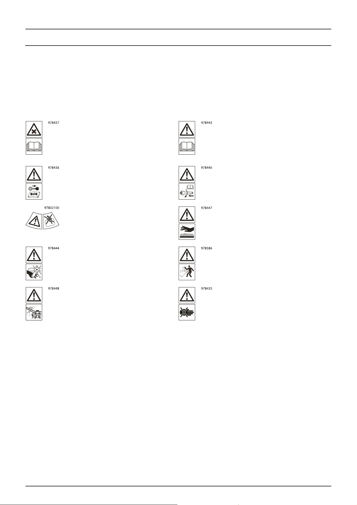
Explanation of Labels
The labels on the sprayer are designating potential dangerous areas on the machine. Operators, or anyone in close range of
the sprayer, must respect these warnings!
The labels should always be clean and readable! Worn or damaged labels must be replaced with new ones. Contact your
HARDI dealer for new labels.
Note that not all labels shown hereafter will apply to your sprayer - this depends on the sprayer model which labels apply.
Chemical handling!
Carefully read the informations about
chemical preparation before handling the
machine. Observe instructions and safety
rules when operating.
Service!
Turn off the engine and remove ignition key
before performing maintenance or repair.
Risk of death!
Do not attempt to enter tank.
Risk of injury!
Do not open or remove safety shields while
engine is running.
Risk of injury!
Service!
Carefully read the Instruction Book before
handling the machine. Observe instructions
and safety rules when operating.
Service!
Tighten to the torque according to instruction
book.
Risk of burn!
Stay clear of hot surfaces.
Risk of injury!
Flying objects - keep a safe distance from the
machine, as long as the engine is running.
Risk of injury!
Keep sufficient distance away from electrical
power lines.
Keep hands away.
18
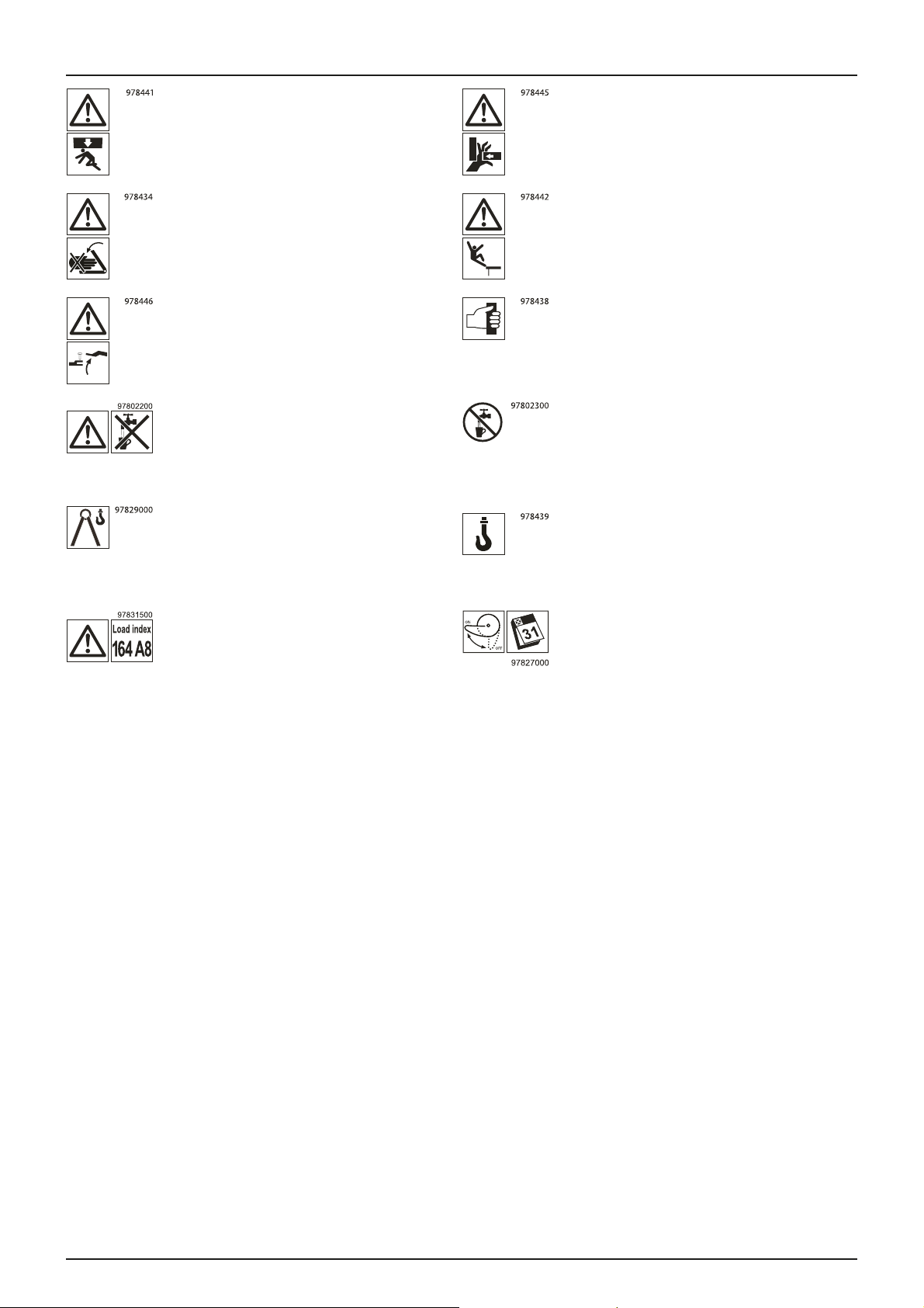
2 - Safety Notes
Risk of squeezing!
Stay clear of raised and unsecured loads.
Risk of squeezing!
Keep hands away, when parts is moving.
Risk of sprayer tipping over!
Be aware when disconnecting the sprayer.
Not for drinking!
This water must never be used for drinking.
Lifting point! Lifting point!
Risk of squeezing
Never reach into the crushing danger area as
long as parts are moving.
Risk of falling off!
Do not ride on platform or ladder.
Grapping area!
Manual handling of the boom etc.
Not for drinking!
This water must never be used for drinking.
Load index!
Max. permitted load rating is 164 at 40 km/h
or 5000 kg.
EasyClean filter service!
Open and clean filter monthly.
19

2 - Safety Notes
Safety and Protection Equipment
Safety at Start-up
Each time before the sprayer is started up, all the safety and protection equipment must be properly attached and fully
functional. Check all safety and protection equipment regularly. Repair or replace the equipment as needed.
Faulty Safety Equipment
Faulty or disassembled safety and protection equipment can lead to dangerous situations.
20

2 - Safety Notes
Informal Safety Measures
Additional Safety Instructions
Together with the safety information in this Instruction Book, also comply with the general and national regulations related to
A. Accident prevention
B. Environmental protection
C. The applicable workplace safety.
Follow these regulations, especially when
• driving on public roads and routes. Comply with the appropriate statutory road traffic regulations. These vary from
country to country, and there may be local regulations which need to be followed.
• local law demands that the operator is certified to use spray equipment.
• using pesticides or liquid fertilizer. Make sure you understand the information from the supplier regarding their use.
21

2 - Safety Notes
Operator Training
Authorized Persons
Only those people who have been trained and instructed may work with/on the sprayer. The operator must clearly specify
the responsibilities of the people in charge of operation and maintenance work.
People being trained may only work with/on the sprayer under the supervision of an experienced operator.
Activity Person
Loading / Transport X X X
Commissioning 0X0
Setup and tool installation 0 0 X
Operation 0X0
Maintenance X X X
Troublesho oting and fault elimination X0X
Disposal X 0 0
Symbols: X - permitted, 0 - not permitted.
Person especially trained for the
activity
1)
Tra in ed
operator
2)
Person with specialist training
(specialized workshop)
3)
1. Persons who can assume a specific task, and who can carry out this task for an appropriately qualified company.
Examples of these persons are truck drivers, machinery dealer and scrap dealers (depending on the activity).
2. Persons who have been instructed in their assigned tasks and in the possible risks in the case of improper behaviour,
who have been trained if necessary, and who have been informed about the necessary protective equipment and
measures. Examples of these persons are customers, farmers and farm workers.
3. Persons with specialist technical training shall be considered as a specialist. Due to their specialist training and their
knowledge of the appropriate regulations, they can evaluate the work with which they have been appointed to and
detect possible dangers. Examples of these persons are sprayer importers, dealers and service engineers and service
technicians.
Comment:
A qualification equivalent to specialist training can be obtained from several years of experience in the relevant field.
If maintenance and repair work on the sprayer is additionally marked "Workshop work", or a similar marking, only a
specialized workshop may carry out such work. The personnel of a specialized workshop shall possess the appropriate
knowledge and suitable aids (tools, lifting and support equipment) for carrying out the maintenance and repair work on the
sprayer in a way that is both appropriate and safe.
22

2 - Safety Notes
Safety Measures in Normal Operation
Protection Equipment
Only operate the sprayer if all the safety and protection equipment is fully functional.
Check the sprayer at least once a day for visible damage and check the function of the safety and protection equipment.
23

2 - Safety Notes
Residual Energy
Possible Dangers
Note that there m ay be residual energy from mechanical, hydraulic, pneum atic and
Use appropriate measures to inform the operators.
Prevent any accidents from happening due to residual energy.
Below are some examples on where the sprayer’s residual energies may be present.
Mechanical Energy
• springs under tension
• weights exposed to gravity
Hydraulic Energy
• trapped oil under pressure in cylinders, hoses and accumulators
• heat from cylinders and oil tank.
Pneumatic Energy
• air tank
• air activated brake system
• pressure dampers for fluid system
Electric Energy
• energy stored in capacitors
• tractor battery
electric / electronic
parts on the sprayer.
24

2 - Safety Notes
Service and Maintenance Work
Statutory Inspection
A surveyor must complete a statutory inspection of the tractor and sprayer prior to connecting the two. However, the rules
often allow the tractor and the sprayer to be inspected separately before being connected.
Each country should regulate the level and frequency of this inspection. Contact your local HARDI dealer for more
information, before using the sprayer the first time.
Preventive Measures
Before carrying out service and maintenance work, secure all media against unintentional start-up. This goes for:
Hydraulic system
• set the tractor’s hydraulic levers in neutral position to relieve oil pressure
• turn off the tractor and remove the ignition key
• dismount the hydraulic hoses connected from the tractor to the sprayer.
Electric system
• turn off the tractor and remove the ignition key
• dismount the electric cables from the tractor’s battery.
Fluid system
• turn off the tractor and remove the ignition key.
Compressed air
• turn off the tractor and remove the ignition key
Carry out prescribed service, maintenance and inspection work in due time. This will help to eliminate faults on the sprayer,
including safety related functions.
Carefully fix and secure larger components to lifting gear when carrying out replacement work.
Check all the screw and bolt connections for firm seating. On completion of the maintenance work, check the function of the
safety devices.
25

2 - Safety Notes
Design Changes
Operator Limitations
You may make no changes, expansions or modifications to the sprayer without an authorization from HARDI. This also
applies when welding support parts.
Any expansion or modification work shall require the written approval from HARDI. Only use modification and accessory
parts approved by HARDI, so that the type approval or other design approvals remain valid in accordance with national and
international regulations.
Vehicles with an official type approval, or with equipment connected to a vehicle with a valid type approval, or approval for
road transport according to the local road traffic regulations, must be in the state specified by the approval.
It is strictly forbidden to:
• Drill holes in the steel frame or in the running gear
• Increase the size of existing holes in the steel frame or in the running gear
• Weld support parts.
Risk of crushing, cutting, catching, squeezing, getting trapped, being drawn in or being struck by sprayer parts due to the
failure of support parts.
Spare Parts, Wear Parts and Aids
Immediately replace any sprayer parts which are not in a perfect state.
Only use genuine HARDI spare and wear parts or those approved by HARDI, so that the type approval remains valid
according to the national and international regulations. The use of spare and wear parts from third parties does not
guarantee that they have been constructed in a way as to meet the requirements placed on them.
HARDI accept no liability for damage caused by the use of non-approved spare parts, wear parts or aids.
26

Cleaning and Disposal
Environmental Protection
Carefully handle and dispose of any materials used, in particular
• When carrying out work on oiled or lubricated sprayer parts.
• When cleaning using solvents.
Always follow local legislation regarding disposal.
2 - Safety Notes
27

2 - Safety Notes
Workstation
Intended Place for Operator
There may be only one person sitting in the driver's seat of the tractor connected to the sprayer. This is the intended
workstation for operating the sprayer.
Risks of Non-Compliance
During the operation or transport of the sprayer:
If another person disturbs or interferes with the operator, or if the operator is trying to operate the sprayer from other places
than the tractor’s driver seat, this can result in negligent or incorrect handling of the vehicle.
• Risk of the operator loosing his concentration and focus on operating the vehicle correctly
• Risk of the operator loosing his ability to operate the vehicle correctly
• Risk of fatal accidents while driving
• Risk of damages to the tractor, sprayer and foreign objects while driving
• Risk of inefficient spraying due to incorrect operation of the sprayer.
28

If the Safety Information is Ignored
Possible Risks and Dangers
Non-compliance with the safety information:
• Can pose a danger to people, to the environment and to the sprayer
• Danger to people through non-secured working areas
• Danger to people through mechanical and chemical influences
• Failure of important sprayer functions
• Failure of prescribed methods of maintenance and repair
• Leakage of hydraulic oil or spray fluid to the environment
• Can lead to the loss of all warranty claims.
2 - Safety Notes
29

2 - Safety Notes
Safety Information For Operators
General Safety and Accident Prevention
Before use or starting up the sprayer and the tractor, always check their
• roadworthiness
• operational safety
Risk of crushing, cutting, catching, squeezing, getting trapped, being drawn in or being struck by sprayer parts due to
inadequate roadworthiness and operational safety.
Beside these instructions, comply with the generally applicable national safety and accident prevention regulations.
The warning symbols and other labels attached to the sprayer provide important information on safe sprayer operation.
Compliance with this information is in the interests of your safety.
Keep the spray boom in folded position, whenever the sprayer is not coupled to a tractor. Unfolding the boom on an
uncoupled sprayer will shift the balance point of the sprayer causing a risk of overturning.
Before driving off and starting up the sprayer, check the immediate area of the sprayer - look out especially for children and
instruct them and other unauthorized persons to stay out of reach of the sprayer. Ensure that you can see clearly.
Drive in such a way that you always have full control over the tractor with the attached sprayer. I n doing so, take your personal
abilities into account, as well as the road, traffic, visibility, weather conditions and the driving characteristics of the tractor and
of the connected sprayer.
Slow down when driving in uneven terrain or when making sharp turns, as the sprayer might be in risk of turning over.
It is forbidden to ride on the sprayer or use it as a means of transport.
It is forbidden to stay in the working area of the sprayer’s drawbar, on the sprayer’s platform or behind the operating area
(the tractor), unless the hydraulic pressure to the sprayer has been switched off.
Only authorized persons are allowed inside or outside the tractor cabin during operation.
Keep persons, children and animals away from the operation areas of the sprayer and from the sprayer’s equipment. Be
careful when manoeuvring the sprayer, especially when reversing, as there is a risk of hitting people or surroundings.
Avoid eating, drinking or smoking while spraying or working with equipment contaminated with chemicals.
The chemicals used for spraying are dangerous to your health! In case of ingestion, poisoning or damages to your skin or
face, immediately seek medical advice. Remember to identify the chemicals used.
30

2 - Safety Notes
Coupling and Uncoupling the Sprayer
Only connect and transport the sprayer with tractors suitable for the task. See the section “Technical Specifications” in this
book to make sure that the tractor matches the requirements to operate the sprayer.
When coupling sprayers to the tractor's three-point linkage, the linkages of the tractor and the sprayer must always be the
same.
Connect the sprayer to the prescribed equipment in accordance with the specifications.
When coupling sprayers to the front or the rear of the tractor, the following may not be exceeded:
• the approved total tractor weight
• the approved tractor axle loads
• the approved load capacities of the tractor tyres
• the approved load capacities of the tractor hitch points.
Secure the tractor and the sprayer against rolling unintentionally before coupling or uncoupling the sprayer.
It is forbidden for people to stand between the sprayer to be coupled and the tractor, while the tractor is moving towards
the sprayer.
Any helpers may only act as guides standing next to the vehicles, and helpers may only move between the vehicles when
both are at a standstill.
If using the tractor's three-point linkage, including lift arms (lower links), secure the operating lever of the tractor’s hydraulic
system, so that unintentional raising or lowering is prevented when coupling or uncoupling the sprayer.When coupling and
uncoupling sprayers, move the support equipment, such as support leg or support wheels (if available), to the appropriate
position (check stability and strength of the ground).
When activating support equipment comprising a hydraulic cylinder, there is a risk of injury from crushing and cutting.
Be particularly careful when coupling the sprayer to the tractor or uncoupling it from the tractor. There are crushing and
cutting points in the area of the coupling point between the tractor and the sprayer.
It is forbidden to stand between the tractor and the sprayer when raising or lowering the three-point linkage.
Coupled supply lines
• must yield to all movements while cornering without tensioning, kinking or rubbing
• must not rub against other parts.
Ropes or cords releasing quick couplings must hang loosely, and they must not release themselves when lowered.
Also ensure that uncoupled sprayers are in a stable position.
31

2 - Safety Notes
Use of The Sprayer
Before starting work, ensure that you understand all the equipment and actuation elements of the sprayer and their
function. There is no time for this when the sprayer is already in operation.
Only wear tight clothes. Loose clothing increases the risk of being caught by the drive shaft / PTO.
Only start-up the sprayer, when all the safety equipment has been attached and in the safety position.
Comply with the maximum load for the connected sprayer and the permissible axle and drawbar loads for the tractor. If
necessary, drive only with a partially filled tank.
It is forbidden to:
• stand in or near the working area of the sprayer
• climb the sprayer
• stand or sit on the sprayer
• stand in the turning and swivel range of the sprayer.
There are crushing and cutting points at externally actuated sprayer points, e.g. hydraulic cylinders.
Only actuate externally actuated sprayer parts when you are sure that no one is standing within the prescribed safety
distance.
Before leaving the tractor:
• lower the spray boom to around waist height above the ground or lower, or
• fold the spray boom into the transport position
•
turn off the tractor engine
key
• remove the ignition
Always keep the sprayer under supervision when:
• the vehicle is parked with the tractor engine running
• the sprayer pump is running
• the tank on the sprayer is being filled.
.
32

2 - Safety Notes
Road Transport
When driving on public roads or highways with the sprayer coupled to the tractor, the following instructions must be
followed. Failure to do so will create a risk of:
• traffic accidents or fatalities!
• damage to the tractor and sprayer.
General Instructions
Comply with the national or local road traffic regulations when using public roads and highways.
When driving in areas with special rules and regulations for markings and lights on sprayers, you should observe these and
equip your sprayer accordingly.
Make sure that you have a clear field of vision when driving.
Check the immediate vicinity of the vehicle; no persons, children or animals must be near the vehicle!
No one is allowed outside the tractor cabin during road transport.
It is forbidden to use the sprayer as a means of transportation of people or goods.
The tractor driver must not be disturbed by other people in the cabin during driving.
Adjust your driving speed to the prevailing conditions.
Before driving downhill, switch to a low gear.
When making turns, lower your speed.
Checking the Vehicle
Before transporting the sprayer on a road, complete the following check points for the tractor and sprayer.
1. Spray boom is folded and resting in transport brackets with the intended locks engaged.
2. Engage transport locks on the steering cylinders.
3. Supply lines for hydraulic, electric and pneumatic systems (if installed) are correctly connected.
4. Parking brake is completely disengaged. Safety line is secured (if applicable).
5. Hydraulic pressure from tractor to sprayer is turned off.
6. PTO drive is turned off, if the main tank is empty. If the main tank is filled with spray liquid, the need for agitation
demands that the PTO drive is turned on.
7. Hitch bolt(s) between tractor and sprayer must be secured with a linchpin or other appropriate means.
8. If the sprayer is coupled onto a lift link drawbar, the lower link should be laterally fixed.
9. Traffic lights and reflectors are in good working order, clean and free from damages.
10. Signs or markings on the vehicle regarding road transport are correctly placed and visible.
11. Brakes are in good working order and free from visible damages.
12. Tyre pressure is correct according to the load.
13. No cables or other parts must be strained or caught in the tractors wheels when cornering.
14. Crop residues and dirt are removed.
15. All moveable or loose equipment are securely latched or stowed away in the designated compartments.
33

2 - Safety Notes
Three-Point Linkage
If the sprayer is fixed to the tractor's three-point linkage or lower links, ensure sufficient side locking of the tractor lower links
before driving off.
Before driving off, secure the operating lever of the three-point hydraulic system against the unintentional raising or
lowering of the connected sprayer.
Carry out a visual check that the upper and lower link pins are firmly fixed with linchpins against unintentional release.
Braking and Steering
Braking distance is increased and steering capabilities are influenced, both when the sprayer’s tank is empty and even more
so with a full tank.
Ensure that the tractor has sufficient steering and braking power. If necessary, use front weights to bring the tractor into a
well-balanced and stable position.
Any sprayers and front/rear weights connected to the tractor influence the driving behaviour and the steering and braking
power of the tractor.
The front tractor axle must always be loaded with at least 20% of the tractor’s empty weight, in order to ensure sufficient
steering power.
Always fix the front or rear weights to the intended fixing points according to regulations.
Comply with the maximum load for the connected sprayer and the approved axle and drawbar loads for the tractor.
The tractor must guarantee the prescribed braking distance for the loaded vehicle combination (tractor plus connected
sprayer).
Before driving off, always switch off independent wheel braking on the tractor (e.g. lock the braking
When turning corners with the sprayer connected, take the broad load and balance weight of the sprayer into account. Slow
down as needed to avoid tilting or overturning of the vehicle, especially on sloping roads.
pedals together).
34

2 - Safety Notes
Hydraulic System
The sprayer is supplied with hydraulic functions operating under a high pressure.
In case of malfunction, there is a risk that the hydraulic system may act inadvertently. This can lead to:
• fatalities or serious injuries to persons or animals in the working area of the sprayer.
• material damages to the sprayer when colliding with trees, vehicles or other objects in the working area of the sprayer.
Ensure that the hydraulic hose lines are connected correctly.
When connecting the hydraulic hose lines, ensure that the hydraulic system is depressurized on both the sprayer and tractor
sides.
The operator controls in the tractor used for hydraulic and electrical movements of components must stay unlocked, e.g. for
folding, swivelling and pushing movements. The movement must stop automatically when you release the appropriate
control. This does not apply to equipment movements that:
continuous
• Are
• Are automatically controlled
• Require a floating position or pressed position to function.
Before working on the hydraulic system:
• Lower the
• Turn off / depressurize the hydraulic system
• Turn off the tractor
• Engage the parking
• Remove the ignition
Have the hydraulic hose lines checked at least once during a calender year by an expert to ensure that they are in safe working
order.
Replace the hydraulic hose lines if they are damaged or worn, which is when:
• It is leaking
• Reinforcement material inside the hose is visible due to cracks in the outer layers.
Only use genuine HARDI hydraulic hose lines.
The hydraulic hoses should not be in use for longer than 5 calender years, including any storage time of maximum 2 years.
Even with proper storage and approved use, hoses and hose connections are subject to natural ageing, thus limiting storage
time and the time of use. However, it may be possible to specify the length of use from experience values, in particular when
taking the risk potential into account. In the case of hoses and hose connections made from thermoplastics, other guide
values may be decisive.
Never attempt to plug leaks in hydraulic hose lines using your hand or fingers. Escaping high pressure fluid (hydraulic oil) may
pass through the skin and ingress into the body. Risk of infection and serious injuries.
spray boom to its lowest position or into the transport position
engine
brake
key
.
If you are injured by hydraulic oil, contact a doctor immediately.
When searching for leaks, use suitable aids to avoid the serious risk of infection and injury.
35

2 - Safety Notes
Electrical System
When working on the electrical system, always disconnect the tractor’s battery.
When disconnecting the battery, disconnect the negative terminal first, followed by the positive terminal.
When connecting the battery, connect the positive terminal first, followed by the negative terminal.
Always place the appropriate cover over the positive battery terminal. If there is accidental earth contact, there is a risk of
explosion.
If climbing onto the sprayer during service work, be aware of the low voltage danger from electric components.
Only use the prescribed fuses. If the fuses used are too highly rated, the electrical system will be destroyed. Risk of fire.
The sprayer m ay be equipped with electronic components whose functions are influenced by electromagnetic interference
from other units. Such interference can pose risks to people, if the following safety information is not followed.:
• If retrofitting electrical units and/or components on the sprayer with a connection to the on-board power supply, the
user is responsible for checking whether the installation might cause faults on the vehicle electronics or other
components
• Ensure that the retrofitted electrical and electronic components comply with the EMC directive 2004/108/EC in the
appropriate version and bear the CE mark.
36

2 - Safety Notes
Universal Joint Shaft
A rotating shaft can catch clothes, tools or aids, if touching or getting in contact with each other. Risk of severe damages and
injuries as the rotating shaft is driven by a powerful torque from the tractor.
Use only the power take-off (PTO) shaft prescribed by HARDI, equipped
with the proper safety devices.
Read and follow the delivered instruction manual from the
manufacturer of the PTO shaft.
The protective pipe and PTO shaft guard must be undamaged, and the
shield of the tractor and sprayer universal joint shaft must be attached
and be in proper working condition.
Safety devices must be in good condition when your are working with the sprayer.
You may install or remove the PTO shaft only after you have done all of the following:
• Switched off the universal joint shaft drive
•
Switched off the tractor engine
•
Removed the ignition
• Applied the parking
A
lways ensure that the PTO shaft is installed and secured correctly both at the tractor end and at the sprayer pump end.
When using wide-angle PTO shafts, always install the wide angle joint at the pivot point between the tractor and sprayer.
Secure the PTO shaft guard by attaching the chain(s) to prevent movement.
Observe the prescribed pipe overlaps in transport and operational positions. See the operating manual from the PTO shaft
manufacturer.
When turning corners, observe the permitted bending and displacement of the PTO shaft.
Before switching on the universal joint shaft, check that the selected universal joint shaft speed (rpm) of the tractor matches
the permitted drive speed of the sprayer.
Stay below the maximum speed (rpm) suitable for the PTO shaft.
Instruct people to leave the danger area of the sprayer, before you switch on the universal joint shaft.
While work is being carried out on the universal joint shaft, there must be no one in the area of the universal joint shaft or
PTO shaft, while it is rotating.
When the tractor engine is turned off, the universal joint shaft must also be switched off. This prevents an unintentional
restart of the universal joint shaft immediately, when the tractor engine is turned on again.
Always switch off the universal joint shaft if it is not needed in action, or if excessive bending of the PTO shaft occurs.
key
brake.
You may work on the sprayer only after all moving sprayer parts have come to a complete stop.
Secure the tractor and sprayer against unintentional starting and unintentional rolling, before you perform any cleaning,
service or maintenance work on universal joint shaft-driven sprayers or PTO shafts.
After decoupling the PTO shaft, place it on the holder provided.
After removing the PTO shaft, attach the protective sleeve to the universal joint shaft stub.
If using a travel-dependent universal joint shaft, note that the PTO speed depends on the drive speed of the vehicle, and that
the direction of rotation reverses, when you drive in reverse.
37

2 - Safety Notes
Working Area of the Sprayer
Before operating the sprayer, the operator must ensure that the area around the sprayer is free.
This working area is defined as the area within the dashed line:
The working area includes the total width of the spray boom as well as the area used for boom folding. Please note the area
immediately behind the sprayer, which is also defined as working area.
The size of the working area depends on the boom type and boom width. The operator must familiarize with the boom at
hand before using the sprayer.
DANGER! Before the hydraulics for the sprayer is activated, there must be no risk of persons, animals or other
€
machines or vehicles entering the working area of the sprayer. Risks of damages and fatalities!
38

2 - Safety Notes
Field Sprayer Operation
Observe the recommendations from the manufacturer of the crop protection product in respect of:
• Personal protective equipment
• Warning information on exposure to crop protection products
• Regulations on dosing, applications and cleaning.
When there will be exposure to the crop protection product:
• Wear the proper personal protective equipment - this may differ depending on the chemical being sprayed.
• Wash and change clothes after spraying
• Wash tools if they have been contaminated.
Observe the information in the national plant protection law.
Keep hoses, pipes or other lines closed, when they are under pressure.
When use of the TurboFiller has ended, make sure that all valves on the TurboFiller are closed / deactivated.
Only use genuine HARDI hoses and hose clamps for replacement, which stand up to chemical, mechanical and thermal
requirements.
The rated volume of the spray liquid tank must not be exceeded during filling. If overfilling, some sprayer functions may be
disabled. However, the main tank is a little oversized to allow for foaming.
When using tractors with a cab with ventilation fans, replace the fresh air filters with activated carbon filters.
Observe the information on the compatibility of crop protections and substances for the field sprayer.
Be aware that some crop protection products have a tendency to stick together or settle when being mixed.
Do not fill the sprayer with water from bodies of water, which are open to the public. This is for the protection of people,
animals and the environment due to the risk of contamination.
Only fill the sprayer using a free flow of water from the mains water supply or from an external water tank.
Environmental Precautions
It is essential to reduce the environmental impact of plant protection chemicals to a minimum. Particularly the soil, subsoil
water, streams, lakes, flora and fauna must be in focus. Contamination of subsoil water must be prevented by paying
particular attention to avoidance of spot contamination of the soil in connection with filling and washing and parking of the
sprayer.
If any concentrated chemicals are spilled on the soil, the contaminated soil should be removed and sent for cleaning at a
capable facility. Follow local regulations regarding disposal. This must be done to avoid seepage of chemicals to the subsoil
waters. Avoid spillage - use the chemical filling device for filling the sprayer with chemicals.
Do not overfill the main tank. The rated volume inside the main tank is stated with large printed numbers on the outside of
the tank. If overfilling, the spray liquid could leak from the sprayer causing contamination of the soil.
Before filling the sprayer with plant protection chemicals, the sprayer must be calibrated to apply the precise dose rate
selected. The important input sensors are the flowmeter, the pressure sensor and the speed sensor.
It is recommended to establish a proper filling and washing location with hard, impenetrable surface drained to a receptacle
if the sprayer is always filled or cleaned on the same spot at the farm. If a washing/filling location is NOT available, the
following precautions should be taken:
• The sprayer should only be filled with clean water at the farm
• The plant protection chemicals must be added and mixed in the field to be sprayed
• Select a different location each time the sprayer is refilled.
39

2 - Safety Notes
Service Work Precautions
Before carrying out any service work, all of the following instructions must be followed in order to prevent damages to the
sprayer, injuries and fatalities:
• Do not walk under any part of the sprayer, unless it is secured. The spray boom is secured when placed in the transport
brackets
• If the spray boom is folded up and resting in the transport brackets for service, check visually that the paralift locks are
engaged (the boom is locked in place)
• If the spray boom is unfolded for service, the boom must be lowered, until it reaches its end stop. Place strong trestles
under the boom for support or use a lifting crane for support
• Never service or repair any equipment while it is operating
• Any service work is preferable carried out on level ground with only authorized persons nearby
• Depressurize the hydraulic system for the sprayer to prevent unintentional movements of the sprayer
• Switch off the PTO
• Switch off the tractor and remove the ignition key to prevent unintentional starting
• Activate the parking brake to prevent rolling
• Put chocks in front of and behind the wheels to prevent rolling
• Electric power must be disconnected from the sprayer
• Any service work on electronic /electric parts must be carried out under dry conditions - no rain or splashes from water
or other liquids.
Cleaning
When cleaning nozzles and filters, lower the spray boom to around waist height above the ground. For safety reasons, do
not walk or stand below the boom or paralift during this cleaning work!
Dispose of oils, greases and filters in the appropriate
Cleaning of tanks:
• Due to toxic vapours from spray liquids in the main tank, climbing into this tank is very hazardous. Cleaning should only
be done from the outside.
• Refrain from entering the main tank.
• Refrain from inspecting any of the tanks with the liquid pump running.
Rinse and wash equipment with clean water after use and before servicing.
way to protect the environment.
40

2 - Safety Notes
Service and Maintenance
Always reassemble all safety devices or shields immediately after servicing.
After a longer period of standstill, the sprayer must be inspected by a qualified operator. Contact your HARDI dealer for more
information.
Repair work in the main tank must only be carried out by a specialized workshop.
Do not attempt to enter the tank.
Access to the rinsing tank must only take place with the spray boom in transport position, and after it is verified that the
transport locks are engaged.
Regularly check the nuts and bolts for firm seating and retighten them as necessary.
If electrical welding is used on the tractor and on the attached sprayer, disconnect the cable to the tractor’s generator and
battery before carrying out electrical welding work on the tractor and on the connected sprayer. Remove all inflammable
or explosive materials from the area to prevent fire.
Pressure test the spray functions with clean water prior to filling with chemicals.
Refrain from dismounting hoses, pipes, or any equipment, if the sprayer is in operation.
Stay below the maximum speed (rpm) suitable for the PTO shaft.
When replacing spare parts, use suitable tools and personal protective equipment.
Spare parts must at least meet the specified technical requirements of HARDI. This is ensured through the use of genuine
HARDI spare
parts.
41

2 - Safety Notes
42

General info
Overview
An overview of where tanks and equipment are installed on the sprayer.
Some items are optional - depending on the specifications for your purchased sprayer.
Left Side
3 - Description
1. Main tank - for water mixed with chemicals for spraying.
2. Rinsing tank - for water to rinse and clean the sprayer.
3. Grab rail - when using the ladder.
4. Left side locker - containing various functions when operating the sprayer.
5. Spray boom - for distributing the spray liquid on the crops.
6. Ladder - for inspecting the top of the sprayer.
7. Liquid valves - pressure, agitation and suction.
8. Clean water tank - for hand washing and minor cleaning jobs.
9. Draining coupler - for pressure emptying of the main tank.
10. Filling coupler - for filling of main tank from external water reservoir.
11. Filling coupler - for filling of RinseTank from external water tank.
12. TurboFiller - for filling of chemicals to be mixed with water.
43

3 - Description
Right Side
13. Right side locker - containing various functions when operating the sprayer.
14. Liquid valve - for directing water to the spray guns.
15. CycloneFilter - for cleaning out impurities in the spray liquid going to the boom nozzles.
16. Storage - for personal protective equipment etc.
17. EasyClean filter - for cleaning out impurities in the spray liquid coming from the main tank.
18. Spray gun - for cleaning the filters with water.
44

Rear Side
3 - Description
19. Distribution valves - each connected a separate boom section for directing the spray fluid to here.
20. Hose reel with spray gun - for cleaning the sprayer on the outside.
21. In-line filters - alternative filters each connected to a separate boom section.
22. Spray nozzles - for creating a spray mist for the crop application.
23. Support wheels - for moving the sprayer at storage.
45

3 - Description
Front Side - Down
24. Three-point linkage - category 2 or 3.
25. Dampers - air-filled rubber cushions for absorbing movements from the sprayer.
26. Transmission shaft (PTO) - for driving the pump on the sprayer.
27. Pump - for directing water and spray liquid around the liquid system.
28. Type sign - with main data for the sprayer.
46

Front Side - Up
29. Pressure gauge - for indicating the current spray pressure.
30. Clogging indicator - for indicating the current state of the EasyClean filter.
31. Level indicator - for indicating the water level in the rinsing tank.
3 - Description
32. Level indicator - for indicating the liquid level in the main tank.
47

3 - Description
Herthadalvej 10 - 4840 Nørre Alslev - Denmark
Production Year
97830600 - Made in Denmark
Model Year
Capacity, litres
-1-
-2-
-3-
-4-
-5-
-6-
-7-
-8-
-9-
Capacity, Gal
Issue
Type
Empty wt. lbs.
Make
Model
Made in USA
97831000
HARDI NORTH AMERICA Inc.
1500 West 76th St. - Davenport, Iowa 52806 - USA.
www.hardi-us.com
Identification No.
-1-
-2-
-3-
-4-
-5-
-6-
-7-
-8-
Identification Plates
An identification plate indicating data for the sprayer is mounted in the
steel frame near the front of the sprayer on the right-hand side.
The identification number for the sprayer is also punched into the steel
frame near the ID plate.
The example to the right is the international model of the ID plate.
If the sprayer is sold to a market requiring another language, the ID plate text might be different. The standard types of ID
plates belonging to sprayers sold to the equivalent markets are shown below.
-4-
-5-
-1-
-2-
-3-
-6-
-7-
-8-
Изготовлен
Модель
-1-
-2-
-3-
-1-
-2-
-3-
OOO “EMC”
Серийный проезд 5 - 400075 Волгоград - Россия
www.hardi.ru
Сделано в России по технологии HARDI
Идентификационный №
-1-
-2-
-3-
Тип
Год выпуска
Емкость, л
Общая масса, кг
Год выпуска модели
-5-
-6-
-7-
-8-
-5-
-6-
-7-
-8-
-5-
-6-
-7-
-8-
-9-
-4-
-4-
-4-
Сделано в России
97831100 -
48

3 - Description
Data
No. Field name Description
-1- Identification No. Coded number identifying the machine. Includes manufacturer, production year, type and ends
with a continuous serial number. The identification number uniquely identifies one specific sprayer
amongst the lot.
-2- Make Manufacturer or brand name. The HARDI group currently have two makes: HARDI and EVRARD.
-3- Model A particular design within a sprayer type.
E.g. type of sprayer models are NK, MASTER, METEOR etc.
-4- Not used Reserved for future use.
-5- Type Defined type – related to type approvals definition: A grouping based on shared characteristics.
E.g. lift sprayer, trailer sprayer, mist blower, field sprayer, self-propelled sprayer etc.
In homologation and type approval context, the “Type” refers to the particular form and shape of
a chassis (i.e. the chassis drawing number). Can be stated encoded.
-6- Production year Year of production start.
In all factories and markets in the EU, the production year is stated in clear text separately. In other
regions, “1521” means “produced in week 52 of the year 2011” etc.
-7- Capacity Rated or nominal content of the main tank. (The tank is oversized to retain overfilling, foam etc.)
-8- Tare mass Same as unladen weight. Vehicle net weight without load, but with fuel, driver etc. Typically the
heaviest configuration is stated for all variants (most vehicles are lighter than the stated tare mass).
-9- Model year Year of shipment from factory.
49

3 - Description
Sprayer Use
The HARDI sprayer is for the application of crop protection chemicals and liquid fertilizers. The equipment must only be used
for this purpose. It is not allowed to use the sprayer for any other purposes.
If no local law demands that the operator must be certified to use spray equipment, it is strongly recommended to be
trained in correct plant protection and in safe handling of plant protection chemicals to prevent unnecessary risk for persons
and the environment, when carrying out your spray job.
Steel Frame
Very strong and compact steel frame / chassis with a strong chemically resistant and weatherproof electrostatic lacquer
coat. Screws and bolts etc. are made of stainless steel, or they have been Delta/Magni-treated to resist corrosion.
Ta nk s
The tanks are made of impact-proof polyethylene, resistant to UV radiation and chemicals.
The main tank has a purposeful design with no sharp corners for easy cleaning.
The filling hole is placed so it can be accessed from the platform. This ensures an easy access for the filling and cleaning of
the tank etc. The sprayer may also be equipped with a TurboFiller, a rinsing tank and a clean water tank. A large, easy-to-read
tank level indicator is placed beside the platform, where it is visible from the tractor cabin and in the work zone of the sprayer.
Nominal main tank contents are 1800 or 2200 litres.
Lifetime
The expected lifetime for the sprayer is 20 years.
To obtain this successfully, these instructions should be followed:
• All service and maintenance work must be completed in due time
• Repair any damages parts as quickly as possible
• Replace or change spare parts as instructed
• Only use original HARDI spare parts.
ATTENTION! If using acidic liquid in a spray boom with stainless steel piping, this will shorten the lifetime significantly,
as these pipes are not acid-proof. Risk of corrosion and leaks.
50

Liquid system
Pump
Diaphragm pump with 6 diaphragms, model 364 or 464.
Standard speed = 540 rpm (6-spline shaft).
The design of the diaphragm pump is simple, with accessible
diaphragms and valves, which ensures that liquid does not contact the
vital parts of the pump.
Pump model 464 is shown on the picture.
3 - Description
Valves and Symbols
The possible functions of valves are distinguished by coloured identification on the function labels. The modular valve
system facilitates the addition of optional extras on both pressure side and suction side.
A function is activated by turning the handle towards the desired function.
ATTENTION! Only the functions used should be open - always close remaining valves.
ATTENTION! If a valve is too tight to operate, or to loose (= liquid leakage, the valve needs to be serviced. Please see
“Adjustment of 3-Way Valve” on page 136 for further information.
Pressure Valve (Green symbols)
This valve is to select which function the pressurized liquid from the pump will be routed to.
The active function is indicated by the indicator.
The handle is turned so the desired symbol is just below the indicator mark. If the handle is turned to a position without a
label with a symbol (unused function), the valve is closed.
Main tank Spraying
Internal tank cleaning
(Rinsing nozzles)
Pressure draining or
TurboFiller
51

3 - Description
Suction Valve (Blue symbols)
This valve is to select suction from main tank, rinsing tank or external tank.
The handle is turned so the desired symbol points to the black mark.
If the handle is turned to a vertical position, the valve is closed.
Main tank Rinsing tank
Filling from external tank
Agitation Valve (Green symbol)
With the adjustable agitation valve it is possible to combine spraying
wi th a hi gh vo lume rate at hi gh pre ssur e wi th agi tati on at t he sa me tim e.
This is controlled continuously by the valve:
The valve is marked with an arrow on the disc which indicates the
amount of liquid that passes through the valve.
Choose your own valve setting, depending on the tank contents:
• The handle is turned to a position near the tip of the arrow: Only a small amount of liquid is allowed to pass the valve
resulting in a lesser extent of agitation.This is recommended when using chemicals with a low density to prevent
foaming in the tank.
• The handle is turned to a position in the wide end of the arrow: A large amount of liquid will pass the valve resulting
in a large extent of agitation. This is recommended when using chemicals with a high density, which will tend to settle
at the bottom of the tank.
External Cleaning Valve (Green symbols)
This valve directs the fluid to the two spray guns used for cleaning.
• Turn the handle to the left to use the spray gun for cleaning the
EasyClean filter and CycloneFilter nearby.
• Turn the handle to the right to use the spray gun connected to the
hose reel for cleaning the sprayer outside.
52

3 - Description
DynamicFluid4 Pressure Regulation
Traditional fluid regulation starts, when the nozzles are opened. With DynamicFluid4 (DF4), the regulation is a continuous
process, even if the nozzles are closed. A synthetic or ceramic disc and a stainless steel disc regulate the pressure and ensure
quick reaction and zero leakages. Used parameters are driving speed, PTO speed and the number of activated boom
sections. The benefit is more precise application rates from the second the sprayer begins spraying.
The DF4 system is based on 5 sensors, which feed the sprayer’s computer with data necessary for optimal regulation. It autoprimes at start-up and starts to move the regulation valve towards the final position, immediately after the operator makes
changes. For example, when section valves are opened or closed, the regulation valve is started at the same time as the
motors for the section valves are started. This prevents overpressure situations e.g. after running empty and refilling of the
main tank.
The sensors are also back-up for each other, ensuring that the system
can continue regulation - even if one or more sensor signals fails.
The applied 5 sensors measure:
1. Driving speed (km/h)
2. Pump speed (rpm)
3. Regulation valve, opening angle (degrees)
4. Fluid flow (l/min)
5. Fluid pressure (bar)
Features for DF4
• Very fast and accurate regulation when all sensors are active, setup in controller menus are correct, and pump, filters
and valves are in good condition. The system measures and calculates 20 times per second.
• Quick reacting valve, when sections are turned on/off, and at speed changes.
• Optimized AutoSectionControl feature that predict boom sections to open and optimized nozzle pressure.
• Optimized for different PTO systems.
• Nozzle surveillance. No setup or tuning is required for nozzle change.
• Controller display can show the current nozzle output, which can be compared with the rated output. A significant
difference in output is caused by failures occurring in the liquid system, such as severe clogging of filters or because of
large leakages on hoses and fittings.
• All functions work through with degraded performance (limp-home modes), if filters are cleaned.
53

3 - Description
Filters
Filters on your sprayer are there to protect the components and prevent nozzle clogging.
An EasyClean suction filter is fitted in the working zone on the sprayer’s right side.
A Cyclone pressure filter is fitted in the working zone on the sprayer’s right side.
In-line pressure filters can be fitted at each boom section.
Nozzle filters are fitted at each nozzle.
A coarse filter is located below the top cover for the main tank.
ATTENTION! All filters should always be in use and their function should be checked regularly. Pay attention to the
correct combination of filter and mesh size. For more, see the chapter “Technical Specifications” in this book.
ATTENTION! Always run your sprayer with cleaned filters to ensure proper functions and to protect the interior of the
pump and valves.
EasyClean Filter
Th is filter co llects impur it ies, whe n l iquid is be ing sucked out of the main
tank by the main pump.
To ensure proper function of the filter and its built-in valve, the filter
must be opened at least once every month. A label on the lid also
designates this.
Besides the spray pressure gauge a clogging indicator is installed. This
works as a vacuum gauge for the filter during operation - the pointer
moves from green towards red, if the filter starts clogging.
Clogging indicator Filter condition
Green area 70 - 100 % capacity.
No cleaning necessary.
Yellow area 55 - 70 % capacity
It is possible to finish an ongoing spray job
and then clean the filter afterwards.
Red area 0 - 55 % capacity
Clean the filter immediately, as it is clogged
too much for proper function.
54

CycloneFilter
With the CycloneFilter, any impurities in the spray liquid will be cleaned
out and returned to the main tank via the return flow.
Function diagram:
1. Filter lid
2. Piping from pump
3. Piping to boom
4. Return to tank
5. Return valve
The return valve (5) has three positions marked with small dots on the
lever:
A. This position is marked with 1 dot:
There is no return flow. This position is used when rinsing the
boom, if there is spray liquid in the main tank. Also used when high
spraying volume is required.
B. This position is marked with 2 dots:
3 - Description
Normal position when spraying. With return flow to prevent filter from clogging during spraying. This position is used
when rinsing the boom, if the main tank is empty.
C. This position is marked with 3 dots:
Flushing position which is used if the filter is clogged. Lift and hold the lever to use this position, which largely increases
return flow and flushes the filter. The pressure valve must be set for “Spraying”.
ATTENTION! Use of position C is no guarantee for a clean filter. Always do a visual inspection and cleaning of the filter.
For more about cleaning, see the section “10 Hours Service - CycloneFilter” on page 148.
DANGER! Never open the Cyclone filter unless the pressure valve is set to “Main tank”. Otherwise spraying liquid may
€
hit you, when opening the filter, and this will also drain the main tank!
55

3 - Description
TurboFiller
The TurboFiller is where you add the chemicals to be mixed with water
in the main tank.
Capacity: approximately 25 litres.
By operating the three levers (A) on the left side of the TurboFiller (C),
you can do the following:
• Stir up the added chemicals with water from the sprayer.
• Transfer the mix to the main tank.
• Clean your chemical container or the TurboFiller inside by using
the flushing nozzle.
A spray gun (B) is also available for further cleaning.
56

RinseTank
One rinsing tank is mounted at the front side of the sprayer . The tank is
made of impact-proof and chemical resistant polyethylene. It is used for
rinsing and flushing of the main tank and liquid system.
Filling is done at the top of the tank. The rinsing tank level indicator is
placed at the front side of the tank.
Capacity: approximately 200 or 243 litres, depending on the main tank
size.
Clean Water Tank
3 - Description
A clean water tank is integrated in the left side of the sprayer.
It is accessed for filling after opening the side cover and unscrewing the
tank lid (A).
The ball valve (B) is opened for water draining.
The water in this tank is for hand washing, for cleaning of clogged
nozzles etc. Only fill this tank with clean water from the tap.
Capacity: 15 litres.
WARNING! Although the clean water tank is only filled with clean
±
water, this water must NOT be used for drinking.
57

3 - Description
Diagram - Basic Liquid System
1. Main Pump
2. Main Tank
3. Suction Valve
4. Pressure Regulation Valve
5. Pressure Valve
6. CycloneFilter
9. Distribution Valves
10. Pressure Gauge
11. Pressure Sensor
12. Spray Boom
13. Agitation Valve
14. Agitation Nozzles
15. Return Line to Main Tank
16. One-Way Valve
Suction lines
Pressure lines
23. TurboFiller
24. Ejector for TurboFiller
26. Tank Hose for TurboFiller
27. Filling Coupler
30. Filler Hose to Tank Inlet
33. Spray Gun for External Cleaning
43. Flowmeter
45. Boost Valve
49. Bypass Valve for Spray Boom
53. EasyClean Filter
54. Spray Gun for TurboFiller
61. Valve for External Cleaning
67. Return Line for Boost Function
69. TurboFiller Cleaning Valve
17. Safety Valve
19. Rinsing Nozzles
20. RinseTank
21. RinseTank Filling Coupler
58
70. TurboFiller Deflector Valve
71. TurboFiller Section Valve
74. Speed Sensor for Pump

Diagram - Liquid System with Options
3 - Description
BoomPrime system
1. Main Pump
2. Main Tank
3. Suction Valve
4. Pressure Regulation Valve
5. Pressure Valve
6. CycloneFilter
9. Distribution Valves
10. Pressure Gauge
11. Pressure Sensor
12. Spray Boom
13. Agitation Valve
14. Agitation Nozzles
15. Return Line / Riser Pipe
16. One-Way Valve
17. Safety Valve
19. Rinsing Nozzles
20. RinseTank
21. RinseTank Filling Coupler
23. TurboFiller
24. Ejector for TurboFiller
26. Tank Hose for TurboFiller
27. FastFiller Coupler
30. Filling Hose to Tank Inlet
31. Pressure Draining Coupler
33. Spray Gun for External Cleaning
34. Restrictor
35. Pressure Control Valve
37. Pressure Gauge
Suction lines
Pressure lines
38. Dilution Valve (On/Off Section Valve)
39. Dilution Valve (S67 Pressure Valve)
40. Dilution Valve (S93 Suction Valve)
41. Dilution Valve for Rinsing
42. One-Way Valve
43. Flowmeter
44. BoomPrime Valve
45. Boost Valve
49. Bypass Valve for Spray Boom
53. EasyClean Filter
54. Spray Gun for TurboFiller
61. Valve for External Cleaning
62. Pressure Relief Line
67. Return Line for Boost Function
69. TurboFiller Cleaning Valve
70. TurboFiller Deflector Valve
71. TurboFiller Suction Valve
74. Speed Sensor for Main Pump
80. Spray Gun for Cleaning Filters
81. Valve for Front Tank Filling
82. Front Tank
83. Rinsing Tank for Front Tank
84. Agitation Pump
85. Agitation Nozzles
86. Rinsing Pump
87. Rinsing Nozzle
88. Valve for Front Tank Suction
59

3 - Description
B
C
D
A A A A A A A ABBB
F
E
BoomPrime
BoomPrime is a low pressure circulation system, which primes the spray boom tubes prior to spraying, ensuring a
homogeneous fluid in the boom tubes and in the main tank. Below the illustration shows the BoomPrime system for the
boom. Components are explained in the diagrams for the liquid systems.
•
The BoomPrime system is attached to each end of a boom section (A).
• The boom spray sections are fed into the middle of each section (B).
Liquid for BoomPrime is led through a valve (D) just before the flowmeter (F). This valve operates in opposite phase:
Operating state Section valves BoomPrime valve
Spraying Open Closed
Not spraying Closed Open
When priming, the direction of liquid flow will be reversed. The liquid will be fed into the nozzle pipes from each end, and
they will then return any water back to the main tank through the return hose for EFC section valves (C).
The BoomPrime pressure is adjusted by the handle on the control valve (E), which includes a pressure gauge.
For adjustment, see the section “BoomPrime Adjustment” on page 96“.
60

3 - Description
Dilution Kit
The dilution kit is a built-in system consisting of the four valves (no. 38, 39, 40 and 41 below) added to the liquid system. This
enables the rinse water to be directed from the RinseTank into the main tank and boom piping to dilute spray liquid residues.
Suction lines
Pressure lines
The dilution kit will facilitate the diluting of chemicals in the main tank or boom piping done from the drivers seat, while
driving in the field. This can be useful when interrupting a spray job, e.g. because of rain or before the tank has to be refilled
at the farm. The dilution kit has two functions which are selected on the controller in the tractor.
• Tank dilution: Water from the RinseTank is sent into the main tank via the rinsing nozzles.
• Boom dilution: Water from the RinseTank is sent into the boom pipes.
NOTE! The dilution kit is NOT a rinsing device. For rinsing the sprayer, please see the section “Cleaning” in this book.
÷
NOTE! Di lutio n of c hemic al re sidue s may be re quire d by law i n cer ta in si tuati ons be for e re turn ing to the fa rm fo r fill ing
÷
or cleaning. Please familiarize with applicable rules and follow these.
61

3 - Description
Hydraulic System
Hydraulic Blocks
Hydraulic blocks installed on the sprayer are described below.
Spray Boom
The main hydraulic block which manages hydraulic pressure for the boom controls.
Open Centre Hydraulics
The open centre hydraulics block is necessary, if the tractor uses open
centre hydraulics and/or load sensing.
The hydraulic block is installed just to the left of the upper link in the 3point linkage for the sprayer.
For adjustment, see “Open and Closed Centre Hydraulics” on page 77.
If in doubt whether your tractor uses open or closed centre hydraulics,
see the tractor’s instruction book or ask your tractor dealer.
62

Spray Boom
Boom and Terminology
The sprayer is fitted with a VPZ boom. The boom is trapeze suspended and hydraulically operated.
Booms are available in 20, 21, 24, 27 and 28 meters working width.
The booms is provided with spring-loaded breakaway in each side.
The terminology is as follows:
A. Centre section
B. Inner section
C. Outer section 1
D. Outer section 2
E. Breakaway section
3 - Description
63

3 - Description
Other Equipment
Nozzle Pressure Gauge
The remote pressure gauge is integrated at the front of the sprayer. This
pressure gauge measures the working pressure in the boom pipes as
close to the nozzles as possible.
The outputs stated in the nozzle charts are always based on the pressure
measured at the nozzle. Both when calibrating and spraying, the
pressure must be adjusted according to the readings of this pressure
gauge.
Canister for Pesticide Information
This canister is for storing information about the present pesticide
product in the tank - such as labels, instructions and safety data sheet
(SDS) from the pesticide supplier.
Information on other products used, such as herbicides, fungicides or
liquid fertilizer must also be stored here.
Unscrew the lid and store this information inside the canister at all times
when using the sprayer.
The canister is placed in the right side locker.
ATTENTION! Although this canister is meant for the storing of
non-contaminated items, it must never be used for the storing of
food, beverage or other items meant for human consumption.
64

Tank Level Indicator
Main Tank
The position of the lever (A) on the scale indicates the actual liquid level,
as the lever is connected to a float inside the tank.
The scale is displayed in litres - multiply by 100 for the reading.
Example: The lever stands at 6 on the scale; this means 600 litres left in
the tank.
The total deviation of accuracy for the level for each scale mark or
readout value is:
± 15 % for volumes up to 10 % of the nominal tank volume.
± 7.5 % for volumes between 10 and 20 % of the nominal tank volume.
± 5 % for volumes above 20 % of the nominal tank volume.
3 - Description
RinseTank
The position of the lever (B) on the scale indicates the actual liquid level,
as the lever is connected to a float inside the tank.
The scale is displayed in litres - multiply by 10 for the reading.
Example: The lever stands at 10 on the scale; this means 100 litres left in
the tank.
ATTENTION! The level indicators for both tanks are only a
guidance for the liquid level in the tank.
For the most accurate reading, park the vehicle on horizontal ground.
65

3 - Description
External Cleaning Device
This equipment comprises a hose reel and a spray gun for cleaning the complete sprayer externally in the field with clean
water, using a spray gun. The External Cleaning Device is located on the boom centre section at the back.
DANGER! The cleaning device produces a water jet with high
€
pressure. Incorrect use may result in injuries!
When using the cleaning device, follow these rules:
• Wear personal protective equipment on your body, feet, hands
and head. Particles and chemical residues can hit you during the
cleaning.
• Any helpers must also wear protective equipment. Keep
bystanders at a safe distance.
• Never point the water jet at people, animals, electrical installations
or other sensitive objects.
• Never use the water jet to clean clothing or footwear.
Night Spraying Light
Floodlights (A) are mounted on the spray boom, and they are positioned
to illuminate both boom wings when spraying at night.
The lights are turned on/off on the controller in the tractor.
20 - 21 m
24 - 28 m
66

3 - Description
AutoSlant
When the AutoSlant function is installed, sensors placed on the boom are used to adjust the main slant angle of the boom
relative to the terrain.
To spray efficiently on hilly terrain, it is important to adjust the boom to be parallel to the terrain.
Ladder
An integrated ladder is available for climbing up to inspect the sprayer
e.g. for looking into the main tank.
Open the left side locker and pull the ladder out.
Unfold it completely before climbing up.
67

3 - Description
68

General Info
Unloading the Sprayer from the Truck
For the unloading of the sprayer, you need a crane. When unloading
with a crane, please observe the lifting points as shown in the picture,
and make sure that the straps or belts used for lifting are strong enough.
DANGER! Lifting of machines require special training according
€
to national regulations.
ATTENTION! Only lift the sprayer when the tanks are empty!
The lifting straps must not put pressure on the black channel for
hoses (A) when lifting, as this can lead to damages.
There are wheels mounted below the sprayer for facilitating the
moving of the sprayer on the ground.
4 - Sprayer Setup
Before Putting the Sprayer Into Operation
Although the sprayer has been supplied with a strong and protective surface treatment on steel parts, bolts etc. in the
factory, it is recommended to apply a film of anti-corrosion oil (e.g. CASTROL RUSTILO or SHELL ENSIS FLUID) on all metal
parts in order to avoid chemicals and fertilizers discolouring the enamel.
If this is done before the sprayer is put into operation for the first time, it will always be easy to clean the sprayer and keep
the enamel clean for many years. This treatment should be carried out every time the protection film is washed off.
69

4 - Sprayer Setup
Selection of Tractor
One or more tractors suitable for the task are selected and tested with the sprayer.
The HARDI dealer will usually assist with this testing.
The owner of the sprayer must keep a document showing which tractors may be used for driving the sprayer. This document
must be available to the operator of the sprayer.
For more on tractor requirements, see “Tractor Requirements” on page 201.
Applicable Tractors
Fill out this form showing the combinations of tractor and sprayer.
Sprayer
Tractor 1
Responsible for testing
Tractor 2
Responsible for testing
Tractor 3
Responsible for testing
Tractor 4
Model: Year: Identification number:
The sprayer has been tested using these tractors:
Model: Year: Identification number:
Name: Date:
Model: Year: Identification number:
Name: Date:
Model: Year: Identification number:
Name: Date:
Model: Year: Identification number:
Responsible for testing
Name: Date:
70

4 - Sprayer Setup
Checking the Suitability of the Tractor
General Info
Before connecting the sprayer to your tractor, you must check the suitability of the tractor. Only connect a tractor which is
suitable for the purpose.
Perform a brake test to check whether the tractor achieves the required braking rate with the sprayer connected.
DANGER! An unsuitable tractor, or improper use of the tractor, causes a risk of:
€
• insufficient tractor stability, steering and braking power
• severe or fatal injuries
• the sprayer being damaged during operation
Requirements for the suitability of a tractor are, in particular:
• Permissible total weight
• Permissible approved axle loads
• Load capacity of the tyres fitted
• Approved front weights must be sufficient
You can find this data on the rating plate of the tractor or in the tractor’s instruction manual or documentation. Ask your
tractor dealer if in doubt.
The front axle of the tractor must always be subjected to at least 20% of the total weight of the vehicle.
The tractor must achieve the braking rate specified by the tractor manufacturer, even with the sprayer connected.
Calculating Actual Weights and Loads
The permissible total tractor weight, specified in the tractor documentation, must be greater than the sum of the:
• Tractor’s tare weight
• Tractor’s ballast and weights
• Sprayer’s total weight
71

4 - Sprayer Setup
A1
A2
A
B
C
D
W2
W1
T1
T3
T2
Data Required for the Calculation
T1 (kg) Tractor empty weight.
See tractor’s instruction book or documentation.T2 (kg) Rear axle load of the empty tractor.
T3 (kg) Front axle load of the empty tractor.
W1 (kg) Total weight of rear-mounted sprayer with a full tank. See the section “Technical Specifications” in this instruction book and add
the weight of your spray liquid for a full tank.
W2 (kg) Total weight of front weights or front-mounted sprayer with a full
tank.
A (m) Distance between the centre of gravity of the front weights, or front-
mounted sprayer with a full tank, and the cen tre of the front axle (total
A1 + A2).
A1 (m) Distance from the centre of the front axle to the centre of the lower
link connection.
A2 (m) Distance between the centre of the lower link connection point and
the centre of gravity of the front weights, or front-mounted sprayer
with a full tank (centre of gravity distance).
Front weights: Total weight of all front weights.
Front-mounted sprayer: See technical data for this equipment and add the
weight of your spray liquid for a full tank.
See tractor’s instruction book or documentation, or data for front weights,
or perform a measurement.
See tractor’s instruction book or documentation, or perform a
measurement.
Front weights: See technical data for front weights.
Front-mounted sprayer: See technical data for this equipment and add the
weight of your spray liquid for a full tank.
Or perform a measurement.
B (m) Tractor wheel base. See tractor’s instruction book or documentation, or perform a
measurement.
C (m) Distance between the centre of the rear axle and the centre of the
lower link connection.
D (m) Distance between the centre of the lower link connection point and
the centre of gravity of the rear-mounted sprayer with a full tank
(centre of gravity distance).
See tractor’s instruction book or documentation, or perform a
measurement.
0.62
Required Minimum Front Weight
To ensure the tractor’s steering capability, the minimum front weight [W2
W1 CD+()T3 B 02, T1 B××+×–×
-----------------------------------------------------------------------------------------------=
AB+
W2
min
] is calculated:
min
72

Actual Front Axle Load [T3] of the Tractor
4 - Sprayer Setup
T3
Actual Total Weight [W] of the Combined Tractor and Sprayer
W2 AB+()T3 BW1 CD+()×–×+×
------------------------------------------------------------------------------------------------=
WW2 T1 W1++=
Actual Rear Axle Load [T2] of the Tractor
T2 WT3–=
Calculation Compared to Permissible Values
B
Actual value according to
calculation
Minimum weight front / rear / kg --
Total weight kg is less than kg
Front axle load kg is less than kg
Rear axle load kg is less than kg
NOTE! Fill in the values in the fields above. You can find the permissible values for the total tractor weight, axle loads
÷
and load capacities in the tractor’s registration papers or in the tractor documentation.
ATTENTION! Add weights to your tractor at the front or rear, if the tractor axle load is exceeded on only one axle.
ATTENTION! If you do not achieve the minimum weight at the front (W2
must add front weights to the tractor.
DANGER! It is forbidden to couple the sprayer to the tractor, if one of the actual calculated values is greater than the
€
permissible value, or if there is no front ballast (if required) mounted on the tractor.
DANGER! When driving on hilly ground, the centre of gravity can change significantly for the combined tractor and
€
sprayer - allow for this when calculating the minimum ballast for the tractor as well as driving carefully. Risk of the
tractor turning over resulting in the driver being crushed or trapped. Risk of impact with the sprayer through
insufficient stability of the tractor and insufficient steering abilities and braking power.
Permissible value according to
the tractor’s instruction book
or documentation.
) from a front-mounted sprayer alone, you
min
73

4 - Sprayer Setup
Transmission Shaft
Operator Safety
1. Always read the manufacturer’s instruction book before applying
any changes to the transmission shaft!
2. Always STOP THE ENGINE and remove the ignition key, before
carrying out maintenance or repairs to the transmission shaft or
implement.
3. Always STOP THE ENGINE before attaching the transmission shaft
to the tractor power take-off (PTO) - most tractor PTO shafts can be
rotated by hand to facilitate spline alignment, when the engine is
stopped.
4. When attaching the shaft, make sure that the snap lock is FULLY
ENGAGED - push and pull the shaft until it locks.
5. Always keep protection guards and chains intact and make sure
that it covers all rotating parts, including CV-joints at each end of
the shaft. Do not use without protection guard.
6. Do not touch or stand on the transmission shaft, when it is rotating
- keep your safety distance at 1.5 meter. Also NEVER cross over a
rotating PTO shaft to reach the other side of the sprayer.
7. Prevent protection guards from rotating by attaching the chains allowing sufficient slack for turns.
8. Make sure that protection guards around the tractor PTO and the implement shaft are intact.
DANGER! A ROTATING TRANSMISSION SHAFT WITHOUT PROTECTION GUARDS IS FATAL!
€
PTO Installation
First installation of the transmission shaft is done in the following way:
1. Attach the sprayer to the tractor and set the sprayer height in the
position with the shortest distance between the tractor and the
sprayer pump PTO shafts.
2. Stop the engine and remove the ignition key.
3. If the transmission shaft needs to be shortened, pull the shaft
apart. Fit the two shaft parts to the tractor and the sprayer pump
and measure how much the shaft needs to be shortened. Also
mark the protection guards with the same length to be shortened.
WARNING! Only shorten the shaft if it is absolutely necessary!
±
The shaft must always have minimum overlap (A) of 1/2 of the sawn
shaft length.
The recommended overlap (A) is 2/3 of the sawn shaft length.
74

4 - Sprayer Setup
Mechanical Connections
Connecting the Sprayer
The sprayer should be placed on a hard and level surface to facilitate the coupling to the tractor.
Reverse the tractor up close to the sprayer in a straight line and pull the handbrake.
1. The tractor and sprayer is connected using the 3-point linkage on
the tractor.
Remember to use cotter pins or similar to secure all three
connection points.
2. Connect hydraulic hoses to the tractor.
3. Connect electric cables to the tractor (after installing the controller
units in the tractor cabin).
4. Connect the transmission shaft (PTO) to the liquid pump.
Adjust the shaft length if necessary.
Connect the chains in both ends.
75

4 - Sprayer Setup
Hydraulic System
General Info
Ensure that the snap couplers are clean before connection!
After having operated the boom and the system has been filled with oil, check the tractor’s hydraulic oil level and top up if
necessary.
DANGER! Test of the hydraulic system should be done very cautiously. There may be air trapped in the system which
€
can cause violent movements of the boom.
DANGER! Hydraulic leaks: Never use your fingers to locate a leakage in any part of the hydraulic system. Due to high
€
pressure, hydraulic oil may penetrate the skin.
Requirements for Tractor
The hydraulic system requires:
• One double-acting outlet for the electro-hydraulic operation of the boom functions.
ATTENTION! The hydraulic hoses are marked with arrows to indicate the direction of oil flow.
ATTENTION! The hydraulic system requires an oil flow between 25 and 130 l/min and a minimum pressure of 180 bar.
WARNING! All hoses MUST be connected. Ensure snap couplers are thoroughly clean before connection. Failure to do
±
so will cause premature wear to the hydraulic system.
76

Open and Closed Centre Hydraulics
This hydraulic block is necessary, if the tractor uses open centre
hydraulics and/or load sensing (LS).
The valves (pos.1 and 2) is factory set for open centre hydraulics, but if
closed centre hydraulics is used (also in combination with load sensing),
screw in the valves clockwise.
WARNING! Always be sure to fully open or close the selection
±
valves for open/closed centre hydraulics.
NOTE! The hydraulic block is accessed from below the sprayer
÷
chassis.
Certain tractor models are able to use Load Sensing without connecting
an external sensing line. But if optimal sensing control pressure cannot
be obtained, an external sensing line needs to be connected to the
tractor.
Connection to Tractor
If Load Sensing (LS) is to be used, connect a hydraulic hose from the
tractor’s LS port to the O-LS port (D) on this hydraulic block.
4 - Sprayer Setup
Connection size for port D is G1/4”.
The restrictors inside the hydraulic block have different orifices
depending on the oil flow returned to the tractor’s oil pump.
A. Orifice is ø0.8 mm (default setting).
B. Orifice is ø1.2 mm
C. Orifice is ø1.6 mm
• Check the hydraulic flow by activating a hydraulic lever in the
tractor. If the reaction time for the hydraulic function is relatively
short, continue your work with this restrictor installed.
• If the reaction time seems too long before the hydraulic function is
enabled, switch the plug (E) in port (A) with the plug (F) in port (B)
to allow more oil flow to pass through.
• If the reaction time is still too long, switch the plug (E) in port (B)
with the plug (F) in port (C).
• Always mount the plug (E) in the port used, and mount the other
plugs (F) in the ports not used.
• Ask your HARDI dealer for correct setup if in doubt.
Combinations of settings for hydraulic block:
Application Valve 1 Valve 2 Port A, B or C
Open centre Out Out No change
Closed centre In In No change
Load sensing (LS) In Out* Change if needed
*If the tractor requires pressure relief, contact your tractor dealer for further advice.
WARNING! It is essential that connectors on the sensing line are kept totally clean, so that impurities do not enter the
±
pump. Impurities may cause damage to vital pump parts.
Before operating the hydraulics, the valve should be set according to the specific tractor model. If you are unsure of
the type of hydraulic system in your tractor, please contact your tractor dealer.
NOTE! A spare part kit for connecting the hydraulic block to the tractor - ask for HARDI item no. 74193800.
÷
77

4 - Sprayer Setup
A
Adjustment of Boom Folding Speed
The main hydraulic block manages hydraulic pressure for the boom
controls.
The throttle valve (A) can adjust the folding speed of the boom.
Check the Folding Speed
• Unfold the boom.
• Fold the outer boom sections calmly into the transport position
without crashing hard against the other boom sections.
The folding speed is set from factory - however it may be adjusted
before use of the sprayer if the operator finds it necessary.
Factory setting:
The valve is screwed completely in and 1/2 turn back out.
ATTENTION! The throttle valve only needs slight adjustments to
change the speed significantly.
ATTENTION! If the boom moves to fast:
Risk of premature wear and tear.
Risk of damaging the boom parts.
To Decrease Folding Speed
• Loosen the counternut.
• Screw the valve inwards.
• Tighten the counternut again.
To Increase Folding Speed
• Loosen the counternut.
• Screw the valve outwards.
• Tighten the counternut again.
ATTENTION! The system must be depressurized during the adjustment.
Tools Nee d e d
Size: 17 mm
Size: 5 mm
78

Electrical Connections
Power Supply
Power requirement is 12 V DC. Always note the polarity!
For proper function of the electric equipment for the sprayer, the tractor
must have the following sizes of electric wires and fuses installed.
Spray box connector, 1-pin plug
The unit requires:
Wire 2.5 mm
2
. Fuse 10 amps.
4 - Sprayer Setup
Hydraulic control unit requires:
Wire 4.0 mm
2
. Fuse 16 amps.
Tractor must follow ISO 4165.
JobCom connector, 3-pin plug
The unit requires:
Wire 6.0 mm
2
. Fuse 25 amps.
Tractor must follow DIN 9680.
ISOBUS connector, 9-pin plug
The unit requires:
Wire 2x 10 mm
2
+ 2x 2.5 mm2 + 2x (2x 0.5 mm2)
The cable is custom made and must not be
changed to another type.
Tractor must follow ISO 11783-2.
Cabin connector for grip control and Setbox:
HARDI item no. 26031500
Traffic light connector, 7-pin plug
The unit requires:
Wire 6x 1.5 mm
2
+ 1x 2.5 mm2.
The cable is custom made and must not
be changed to another type.
Tractor must follow ISO 1724.
Power and data connector, 13-pin plug
Used for controller model HC 6500.
If needed, buy one of these tractor kits to
complete the setup:
HARDI item no. 26049400 (incl. NORAC system)
HARDI item no. 26013900 (excl. NORAC system)
Tractor must follow ISO 11446.
The delivered power connectors follow the standard of most modern tractors. If you have a tractor with another power
connector, it is necessary to disassemble the connector and fit it to the actual sprayer connector. Contact your HARDI dealer.
The delivered connectors may vary on the sprayer, depending on its equipment and scope of supply.
Road Safety Kit
If rear lights are installed, connect the plug for rear lights to the tractor’s
7-pin socket and check the function of rear lights, stop lights, side lights
and direction indicators on both sides before driving.
The wiring is in accordance with ISO 1724. See the chapter “Technical
Specifications” in this Instruction Book.
ATTENTION! Turn OFF all work lights when driving on public roads!
79

4 - Sprayer Setup
100 -120mm
A
B
C
Installation of Control Unit Brackets
Find a suitable place in the tractor cabin to mount the control units.
Best recommended position is to the right of the driver seat.
The supplied tractor pillar bracket (A) has a hole spacing of 100 and 120
mm, which fits most tractors. Threaded mounting holes may be hidden
behind front corner cover. Check the tractor’s instruction book for
information regarding attachment points.
Three mounting tubes (B) are supplied. One, two or all three may be
used. They can be bent and shortened. A spacer (C) is also supplied to
allow further attachment possibilities. Find the best solution for your
tractor or vehicle.
Tube (B) plate is staggered so that, if correctly orientated, all boxes will
line up.
ATTENTION! See also the controllers instruction book for further
details of fitting the controller equipment.
Speed Transducer for Tractor
Note the following if the speed transducer is fitted to the tractor.
The speed transducer (A) and the speed ring should be located at the
inside of the tractor’s right wheel.
The sensor is an inductive type that requires a metallic protrusion (e.g. a
bolt head) passing by in order to trigger a signal. It should be adjusted,
so that the transducer is placed to the centre of the holes in the speed
ring (vertical direction).
• Recommended distance between speed ring and transducer (A) is
4 mm ± 2. Check this in the entire circumference of the ring when
spinning the wheel by hand.
Correct fitting is indicated by a constant flashing of the transducer, when
the wheel is rotating.
80

Liquid System
CycloneFilter
Standard filter size is 80 mesh and can be changed by opening the filter
top.
Check condition of O-rings and lubricate if necessary, or replace them if
damaged, before reassembly.
4 - Sprayer Setup
DANGER! Never open the Cyclone filter unless the suction valve
€
is turned to the unused position, and the pressure valve is set to
“main tank”.
Otherwise spraying liquid may hit you, when opening the filter
and thereby draining the main tank!
81

4 - Sprayer Setup
A
BoomPrime Adjustment
The BoomPrime system works within a fixed pressure range of around 3 bar, but it must be adjusted for the specific spray
job (due to different choice of nozzles etc.):
1. Unfold the spray boom and start the PTO.
2. Set pressure valve to “Spraying”, suction valve to “Main tank” and agitation valve to “Agitation”.
Only open the agitation valve to suit the tank contents, e.g. half open.
3. Adjust the spray pressure to what will be used when spraying.
Close all nozzles.
4. Turn the BoomPrime adjustment screw (A) to increase the
BoomPrime pressure to 3 bar or until the nozzles start to drip.
5. If nozzles leak, then lower the BoomPrime pressure by 1 bar on the
adjustment screw (A).
ATTENTION! If not adjusted correctly, the nozzles will not close
(i.e. they will drip), when the spraying is stopped, or the tubes will
not be primed.
The possible priming circulation speed of BoomPrime relies on the nondrip valves to keep the nozzles closed. If an extended amount of
circulation is necessary, the non-drip valves can be changed to a version
with higher pressure setting (later opening time).
Non-Drip Valve Opening Pressure (bar)
Green (standard) 0.5
Yellow 0.7
82

Spray Boom
Adjustment of Suspension Effect
In order to adjust the behaviour of the boom, the trapeze has 2 settings.
Setting Behavior
1 All-round standard setting (Factory setting).
2 Trapeze is moving slower when driving in the field.
Good at following slopes, but less compensating for obstacles.
How to Change the Setting
1. Unfold and support the centre section (X).
4 - Sprayer Setup
DANGER! Do not change this boom setting, unless the boom is
€
fully supported in a safe way!
2. Loosen the locking bolt (A).
3. Remove the cross pin + split pin (B).
4. Place (B) in new setting position (1-2).
5. Fasten the locking bolt (A) again.
Carry out similar adjustments to both sides of the trapeze.
83

4 - Sprayer Setup
Anti-Yaw Mechanism
The boom is equipped with cone-shaped rubber dampers for damping
the yaw movements when driving in the field.
Adjust the damper positions if needed by turning the nut for each
damper.
Use a wrench size 19 mm.
84

5 - Operation
General Info
Environmental Info
For environmental info, please refer to the following parts in the Spray Technique Book:
• Nozzles.
• Spray quality.
• Choosing nozzles for arable crops.
• Spraying speed.
Sprayer Use
The HARDI sprayer is for the application of crop protection chemicals and liquid fertilizers. The equipment must only be used
for this purpose.
If the sprayer is to be used for any other purposes than the ones described in this instruction book, a new risk assessment
and a workplace assessment must be completed for this use. This obligation lies with the owner and operator according to
EU directive 2009/104/EC - see “Before First Use of the Sprayer” on page 11.
Improper use of the sprayer results in risks to your safety, health, and even a risk of death.
If no local law demands that the operator must be certified to use spray equipment, it is strongly advised to be trained in
correct plant protection and in safe handling of plant protection chemicals to prevent unnecessary risk for persons and the
environment, when carrying out your spray job.
85

5 - Operation
Symbols for Valves
The following symbols are shown on labels on the sprayer, where the operator can set a valve to stop or start a function.
The labels must be readable when operating the sprayer. Damaged or unreadable labels must be replaced.
The symbols are explained here.
Symbol on label Symbol description Label color HARDI item number
Suction from main tank Black / Blue 97809900
Suction from RinseTank Black / Blue 97810000
Fillin g of main ta nk from e xter nal
tank
Filling of main tank Black / Green 97810300
Spraying / Pressurized nozzles Black / Green 97810400
Cleaning of main tank inside Black / Green 97810500
Pressure emptying of main tank
to external tank
Agitation in main tank Black / Green 97810900
External cleaning Black / Green 97811000
Filling of RinseTank Black / Green 97810800
Black / Blue 97810100
Black / Green 97810600
86
Pressure emptying of main tank
and TurboFiller to external tank
Cleaning of empty chemical
containers
Agitation in TurboFiller Black / Yellow 97821500
Filling of main tank from
TurboFiller
Black / Green 97825500
Black / Yellow 97821600
Black / Yellow 97821400

5 - Operation
Spray Boom
Safety Info
Keep the spray boom in folded position while driving outside the field. Park the sprayer and tractor on level ground before
using the folding/unfolding functions.
Failure to comply will damage the boom and cause dangerous situations to people and the surroundings.
DANGER! Before unfolding the boom it is important to connect the sprayer to the tractor’s hitch point to prevent
€
overbalancing of the sprayer. Activate the tractor’s handbrake.
DANGER! When folding or unfolding the boom, make sure that no persons or objects are within the operating area
€
of the boom.
DANGER! Always follow the guidelines listed below when driving in areas with overhead power lines:
€
Keep from using the folding/unfolding functions in areas with overhead
power lines. Unintended boom movements may cause contact with
overhead power lines, causing a risk of fatal accidents.
ATTENTION! A label (HARDI item no. 978448) follows the sprayer.
This label must be placed in the cabin visible from the operator’s
seat.
Operating the Grip
The buttons on the grip in the tractor controls the following sprayer functions in the field:
A. Status light for power ON/OFF.
The light must be ON.
B. Boom tilt up/down - left boom side.
Adjust the boom height individually for the right and left boom
side, if the terrain is hilly.
C. Boom tilt up/down - right boom side.
D. Boom slant - left boom side.
Adjust the boom height to match the slope, when driving across a
hillside.
E. Boom slant - right boom side.
F. Main ON/OFF for spraying.
Turn it ON for spraying, OFF to stop spraying.
G. Boom height up.
Aim for a height of 50 cm above the crop when spraying.
H. Boom height down.
I. Boom sections spraying ON/OFF.
Switch pushed up is OFF; down is ON.
J. Not used.
87

5 - Operation
Maneuvering of the Boom
Applicable for HC 6500 / HC 8600 / HC 9600 / ISOBUS.
WARNING! The folding functions must only be operated, when the sprayer is stationary! Failure to do so will damage
±
the boom.
ATTENTION! The boom can not be operated with the tractor’s hydraulic levers.
Transport Lock
A cone-shaped mandrel (M) is connected to the boom structure on
both sides of the boom centre.
When the boom is folded correctly for transport position, the mandrels
sit in the chassis. At this position the boom is locked against moving
sideways when driving and locked against folding / unfolding.
The boom should be resting on the rubber pads (N) during transport.
DANGER! The transport locks must both be functioning correctly
€
before road transport. If not, there is a risk of unintentional boom
movements when driving, which can lead to road accidents!
Folding Indicator
From the tractor cabin, look for the yellow indicator (O) to be visible in
the slot hole in the black plate (P). The indicator moves up or down as
the boom is raised or lowered.
When the indicator is visible, the boom is clear of the transport lock and
ready for unfolding / folding.
ATTENTION! This picture is a view from the rear of the sprayer.
88

How To Unfold the Boom
11. Press the button (G) to lift the boom clear of the transport lock check the position of the yellow folding indicator.
12. The symbol is now shown on the display.
If not, lock the trapeze by pushing for approx. 5 seconds; this
will activate the chain lock in the boom centre.
13. Press the button (K) to unfold the boom sections.
They will unfold one at a time.
14. Press the button (H) to lower the boom to the correct working
height.
15. Unlock the trapeze by pushing for approx. 5 seconds.
The symbol is now shown on the display.
How To Fold the Boom
5 - Operation
1. Press the buttons (D) or (E) to set a neutral slant angle (no slant).
2. Lock the trapeze by pushing for approx. 5 seconds; this will
activate the chain lock in the boom centre.
The symbol is now shown on the display
3. Press the button (G) to raise the boom - check the position of the
yellow folding indicator.
4. Press the button (L) to fold the boom sections.
5. Press the buttons (B) and (C) to position the boom wings vertically,
so the transport locks can be engaged.
6. Press the button (H) to lower the boom, until it is resting on the
rubber pads and the transport locks are in locking position.
L
K
MN
89

5 - Operation
Operating the Control Unit While Spraying
The SetBox in the tractor control the following functions in the field:
Power ON/OFF/status, LED light. The light must be ON.
Automatic spray pressure regulation.
The regulation valve controls the main spray pressure. This is
default selection when the controller is powered ON, and it
should remain here during normal spraying.
Manual spray pressure regulation.
During normal spraying, these regulations should not be
used, as the regulation valve does this automatically.
Optional functions, A or B.
E.g. for night spraying light on the boom:
A: Turn lights on; B: Turn lights off.
If traffic lights are installed, the work lights will only work,
when the traffic lights are turned on.
Optional function.
E.g. end nozzle at the tip of the boom:
Select between angled end nozzle and standard nozzle.
NOTE! Check the current application rate on the display, or see the instruction book for the spray controller for more
÷
information.
90

5 - Operation
Liquid System
General Info
Please refer to the Spray Technique book for instructions on the use of filters, nozzles etc., and their combination in use with
specific spraying applications.
Quick Reference - Operation
In the following diagram, the handle positions for different options are described.
91

5 - Operation
Filling/Washing Location Requirements
When filling the sprayer with chemicals and water, it is important to avoid spot contamination by spraying chemicals in
order to protect the subsoil water resources.
At a dedicated filling site
If the sprayer is always filled on the same location, a special filling/washing location should be established. This should have
a hard, liquid-impenetrable surface (e.g. concrete) securing against seepage, together with edges securing against run-off
to the surrounding areas. The location should be drained to an adequate receptacle (e.g. slurry tank or similar).
Any spillage or washings should be retained and diluted in order to be distributed in a larger area. This is to ensure minimal
environmental impact and avoid build-up of larger chemical concentrations at one spot.
If no other requirements of distances exist, the following general recommendation of distance can be used. Filling location
must be no closer than:
1. 50 metres from public water supplies for drinking purposes, and
2. 25 metres from non-public water supplies for drinking purposes and from treatment sumps and cesspools of drainage
systems, and
3. 50 metres from surface water (watercourses, lakes and coastal waters) and from nature reserves.
In the field
Alternatively the sprayer can be filled in the field, where the spraying is to take place. If so, choose a different location for
each refilling.
If no other requirements of distances exist, the filling should not take place closer than:
1. 300 metres from public or non-public water supplies for drinking purposes, and
2. 50 metres from surface water (watercourses, lakes and coastal waters), treatment sumps, cesspools of drainage
systems, and nature reserves.
ATTENTION! Legislation and requirements vary from country to country. Always follow local legislation in force.
ATTENTION! It is the responsibility of the sprayer owner/operator to comply with all relevant legislation. HARDI
cannot undertake any responsibilities for incorrect operation and use.
Filling of Water
The tank should normally be filled 1/3 with water before adding
chemicals. Always follow the instructions given on the chemical
container!
WARNING! If the sprayer is put aside with liquid in the main tank,
±
all manifold valves must be closed.
92

5 - Operation
Filling Through Tank Lid
Water is filled into the main tank by removing the big tank lid, which is located at the top of the sprayer. The tank lid is
accessible from the ladder. It is recommended to use as clean water as possible for spraying purposes. Always fill water
through the strainer basket to prevent foreign particles from entering the tank. An overhead tank can be used in order to
obtain high filling capacity.
WARNING! Do not let the filling hose enter the tank. Keep it
±
outside the tank, pointing towards the filling hole. If the hose is
led into the tank, and the water pressure drops at the water
supply plant, chemicals may be sucked back and contaminate
the water supply lines, supply plant and supply well.
The water supply line should be provided with a check valve as
additional safety precaution. Follow local legislation in force at
any time.
The water supply should be provided with a water meter to avoid
spillage by overfilling. Follow local legislation in force at any time.
External Filling Device
The External Filling Device (if installed) is operated as follows:
1. Remove the cap (A) and connect a suction hose to the suction
manifold.
2. Turn pressure valve to “Main tank”.
3. Turn suctionvalve to “External Filling Device”.
4. Engage the pump and set PTO revolutions at max. 540 rpm.
5. The tank is now filled with water. Keep an eye on the liquid level
indicator.
6. Turn handle on suction manifold away from Filling Device to
discontinue filling process. Now disengage the pump. Disconnect
suction hose and replace the cap.
DANGER! Prevent contamination or injury. Do not open suction
€
valve towards the Filling Device, unless the pump is running and
the filling hose is connected. If this valve is opened without the
pump running, liquid will stream out of the coupler.
WARNING! Do not leave the sprayer while filling the tank, and
±
keep an eye on the level indicator in order NOT to overfill the
tank.
ATTENTION! Observe local legislation regarding use of filling device. In some areas, it is prohibited to fill from open
water reservoirs (lakes, rivers etc.). It is strongly recommended only to fill from closed reservoirs (mobile water tanks
etc.) to prevent contamination.
93

5 - Operation
Filling of Rinsing Tank
The rinsing tank is filled via the 1” threaded connection piece (A):
1. Remove the filler cap, then fit the external water hose to the
threaded connection piece.
2. Engage external water pump, if any.
3. Keep an eye on the level indicator in order not to overfill the tank.
4. Stop filling and refit the cap.
Volume: approximately 200 or 243 litres.
ATTENTION! Only fill rinsing tank with clean water! To avoid algae
developing in the rinsing tank, always drain this tank, if the
sprayer is not in use for a longer period of time.
ATTENTION! For cleaning and inspection purposes, the rinsing
tank is accessible via the tank lid on top of the tank.
94

Filling of Clean Water Tank
To fill the clean water tank:
1. Remove the tank lid (A).
2. Fill with clean water.
3. Refit the tank lid.
For use of water:
• Turn the lever to open the ball valve (B).
The water from this tank is for hand washing, cleaning of clogged
nozzles etc.
WARNING! Although the clean water tank is only filled with clean
±
water, this water must NOT be used for drinking.
ATTENTION! Only fill this tank with clean water! To avoid algae
developing in the clean water tank, always drain this tank, if the
sprayer is not in use for a longer period of time.
5 - Operation
External Filling Device
The External Filling Device (if installed) is operated as follows:
1. Remove the cap (A) and connect a suction hose to the suction
manifold.
2. Turn pressure valve to “Main tank”.
3. Turn suctionvalve to “External Filling Device”.
4. Engage the pump and set PTO revolutions at max. 540 rpm.
5. The tank is now filled with water. Keep an eye on the liquid level
indicator.
6. Turn handle on suction manifold away from Filling Device to
discontinue filling process. Now disengage the pump. Disconnect
suction hose and replace the cap.
DANGER! Prevent contamination or injury. Do not open suction
€
valve towards the Filling Device, unless the pump is running and
the filling hose is connected. If this valve is opened without the
pump running, liquid will stream out of the coupler.
WARNING! Do not leave the sprayer while filling the tank, and
±
keep an eye on the level indicator in order NOT to overfill the
tank.
ATTENTION! Observe local legislation regarding use of filling device. In some areas, it is prohibited to fill from open
water reservoirs (lakes, rivers etc.). It is strongly recommended only to fill from closed reservoirs (mobile water tanks
etc.) to prevent contamination.
95

5 - Operation
Safety Precautions - Crop Protection Chemicals
Always be careful when working with crop protection chemicals!
WARNING! Always wear proper protective clothing before handling chemicals!
±
Personal protection
Depending on chemical type, protective gear/equipment should be worn to avoid contact with the chemicals, such as:
• Gloves
• Waterproof boots
• Headgear
• Respirator
• Safety goggles
• Coverall with chemical resistance
WARNING! Protective clothing/equipment should be used, when preparing the spray liquid, during the spray job and
±
when cleaning the sprayer. Follow the chemical manufacturer’s instructions given on the chemical label and/or local
legislation.
WARNING! It is always advisable to have clean water available, especially when filling the sprayer with chemicals.
±
WARNING! Always clean the sprayer carefully and immediately after use.
±
WARNING! Only mix chemicals in the tank according to directions given by the chemical manufacturer.
±
WARNING! Always clean the sprayer before changing to another chemical.
±
96

Operating the TurboFiller
The TurboFiller is where you add the chemicals to be mixed with water in the main tank.
Capacity: approximately 25 litres.
Before Use
• Open the grey side cover on the left side of the sprayer.
• Pull out the TurboFiller towards you, until it locks into position.
5 - Operation
• Remove the lid and place it on the bracket.
On the next page is a short description on how to operate the valves by
using the levers to the left of the TurboFiller.
For more details, see the following sections in this Instruction Book
about the procedure for operating the TurboFiller while filling
chemicals.
97

5 - Operation
TurboFiller Suction Valve
The valve is used simultaneously with the TurboFiller. The valve has 2
settings: Continuously open or spring-loaded normally closed.
Open the valve by lifting the lever up, when chemicals are to be filled
into the TurboFiller and transferred to main tank.
TurboDeflector Valve
This TurboDeflector valve activates the vortex flushing of the TurboFiller.
Lift the lever to lock it in open position for continuous liquid rotation in
the hopper.
Rinsing of Chemical Containers
The upper lever is used for two purposes.
1. When the TurboFiller lid is open:
For rinsing empty containers. Place the container over the rotating
flushing nozzle in the middle of the TurboFiller to rinse the inside
of the container.
2. When the TurboFiller lid is closed:
Use the lever to rinse the hopper, when the filling of chemicals is
completed.
DANGER! Do not activate this lever, unless the multi-hole nozzle is covered by a container, as spray liquid may
€
otherwise hit the operator! Risk of injuries and spillage on the ground.
After Use
• Clean the inside of the TurboFiller with the spray gun to remove
chemical residues.
• Put the lid back on top of the TurboFiller.
98

• To the right of the TurboFiller, push the red handle outwards to the
right to unlock the fixed position. At the same time, push the
TurboFiller back into the storage position.
5 - Operation
• Place the spray gun (A) on the handle for the lid.
• Close the grey side cover - make sure it locks in the right side (B).
99

5 - Operation
Filling Liquid Chemicals Using the TurboFiller
ATTENTION! We advice to use the TurboFiller, when you fill chemicals on the sprayer.
1. Fill the main tank at least 1/3 with water (unless otherwise stated
on the chemical container label).
2. Turn the handle of the suction valve towards “Main tank”.
Turn pressure valve towards “Pressure draining/TurboFiller”.
Close the agitation valve.
ATTENTION! If filling water from an external tank, this can be
continued while doing the next steps.
DANGER! Before turning Pressure SmartValve to “Pressure
€
draining/TurboFiller” it is very important to be sure that the quick
coupler lid is correct and completely mounted to the filling stud
into its locked position. Failure to do so may cause risk of
contamination and injury from quick coupler lid being “shot” off
when pressurized! If not possible to mount the lid completely,
lubricate the rubber seal and the grip hooks.
3. Engage the pump and set PTO speed at max. 540 rpm.
4. Open TurboFiller lid. Measure the correct quantity of chemical and
fill it into the hopper.
DANGER! Always wear face shield and other appropriate personal
€
safety equipment, when filling chemicals.
ATTENTION! The scale in the hopper can only be used, if the sprayer is parked on level ground! It is recommended to
use a measuring jug for best accuracy.
5. Engage the hopper transfer device by opening the TurboFiller suction valve to transfer chemicals to the main tank.
The TurboFiller suction valve must be open for at least 20 seconds after the chemical is no longer visible in the hopper,
in order to empty the transfer hoses completely into the main tank.
DANGER! If the TurboFiller and the transfer hoses are not completely emptied, there is a risk of chemicals being
€
sucked out of the main tank!
6. If the chemical container is empty, it can be rinsed by the Chemical Container Cleaning device. Place the container
over the multi-hole nozzle and push the container for cleaning.
DANGER! In order to avoid spray liquid hitting the operator, do not press the lever, unless the multi-hole nozzle is
€
covered by a container, as spray liquid may otherwise hit the operator!
ATTENTION! The rinsing device uses spray liquid to rinse containers for concentrated chemicals. Before disposal,
always rinse the chemical containers with clean water several times, until they are clean.
7. Flush the TurboFiller with clean water from the rinsing tank or from an external tank by shifting to suction. The
TurboFiller suction valve must be open for at least 20 seconds after the rinse water is no longer visible in the hopper,
in order to empty the transfer hoses completely into the main tank.
ATTENTION! If not flushed with clean water, the hopper rinsing device uses spray liquid for rinsing the hopper!
Cleaning the TurboFiller must always be done, when the spray job is ended, and together with cleaning the entire
sprayer. A cleaning after the last filling, and before spraying, does not ensure a clean TurboFiller!
8. Close the TurboFiller suction valve, when the hopper has been rinsed. Close the lid.
100
 Loading...