

Page 1

MEGA 230/350 CENTRIFUGAL
OPERATOR’S MANUAL
10545903 (3/96)
Page 2

Page 3

MEGA 230 /350 CENTRIFUGAL
OPERATORS MANUAL
HARDI reserves the right to make changes in design,
material, or specification without notice thereof.
HARDI MEGA 230 / 350 CENTRIFUGAL OPERATORS MANUAL
Part No. 105459 3/96
1
Page 4

TABLE OF CONTENTS
1.0 INTRODUCTION 7
2.0 SAFETY INFORMATION 8
2.1 Follow Safety Instructions 9
2.2 Operating the Sprayer Safely 9
2.3 Handling Chemical Products Safely 11
2.4 Local Poison Information Center 12
3.0 GLOSSARY OF TERMS 13
4.0 ASSEMBLING THE MEGA SPRAYER 14
4.1 Lifting points 14
4.2 Preparing Wings for Installation 15
4.3 Installing Boom Wings 15
4.4 Mounting Hydraulic Hoses 16
4.5 Installing Center Frame Spray Tube Assembly 18
4.6 Adjusting Center Cables 19
4.7 Attaching Feed Hoses - Three Valve System 20
4.8 Performing Final Inspection 21
5.0 MOUNTING THE MEGA SPRAYER 22
5.1 Dismounting the Mega Sprayer 23
5.2 P.T.O. Shaft Operator Safety 24
5.3 Installation of P.T.O. Shaft 24
5.4 Hydraulic Requirements with Eagle Boom 27
5.5 Hydraulic Hook-Up 27
5.6 HZ Hydraulics 28
5.7 Installation of Handle 28
5.8 Electric Hook-Up of Handle 28
5.9 Control Box for E.S.C. Controls 29
6.0 OPERATING INSTRUCTIONS 30
6.1 Filling the Main Tank 30
6.2 Filling the Flush Tanks 30
6.3 Standard Sprayer Plumbing Diagram 30
6.4 Operating The Mega Boom 31
6.5 Unfolding & Folding the Boom (HY Hydraulics) 31
6.6 Unfolding & Folding the Boom (HZ Hydraulics) 32
6.7 Tilting the Boom (HZ Models Only) 32
2
HARDI MEGA 230 / 350 CENTRIFUGAL OPERATORS MANUAL
Page 5

TABLE OF CONTENTS: Continued
6.0 OPERATING INSTRUCTIONS (cont'd)
6.8 Operation of the ESC Controls 33
6.9 Agitation Adjustment 35
6.10 Manifold System 36
6.11 Manifold System Operating Instructions 38
6.12 Agitation Bypass Valve Operation (Optional) 39
6.13 Operation of the Tank Drain Valve 39
6.14 Nozzle Selection 41
6.15 Calibration 44
7.0 MAINTENANCE 48
7.1 Cleaning the Sprayer 48
7.2 Filters 50
7.3 Lubrication 51
7.4 Greasing the H-Frame & Center Frame 52
7.5 Greasing the Boom 53
7.6 Lubrication of Chain & Sprocket 54
7.7 Greasing the Breakaway Clutch 54
7.8 Maintenance of Triplets 55
8.0 ADJUSTMENTS 56
8.1 Adjustment & Maintenance Intervals 56
8.2 Checking and Adjusting Sprocket Timing 57
8.3 Aligning Wing Assemblies 57
8.4 Aligning Intermediate and Outer Boom Sections 58
8.5 Adjusting Front Fold Cables 59
8.6 Adjusting Breakaway Clutch Tension 60
8.7 Adjusting Boom Wing to be Level 61
8.8 Adjusting Floating Frame Pivots 63
8.9 Adjusting Boom Transport Postion 64
8.10 Adjusting Rear Cable 64
9.0 WINTER STORAGE 65
10.0 OPERATIONAL PROBLEMS 66
10.1 Nozzle Tubes and Fittings 67
10.2 Checking the Valve Cone in Distributor Valves 67
HARDI MEGA 230 / 350 CENTRIFUGAL OPERATORS MANUAL
3
Page 6

TABLE OF CONTENTS: Continued
10.0 OPERATIONAL PROBLEMS (cont'd)
10.3 Emergency Operation of E.S.C. Control 68
10.4 Level Indicator 68
11.0 TROUBLESHOOTING 69
11.1 General Spray Systems 69
11.2 Foam Marker 71
11.3 Flush & Rinse
TM
72
11.4 Chemical Filler 72
11.5 Hydraulics 73
11.6 HY Hydraulics - Schematic 74
11.7 HZ Hydraulics - Schematic 75
12.0 ACCESSORIES 76
12.1 Chemical Filler 76
12.2 Chemical Filler Rinse Kit 76
12.3 Flush System 77
12.4 Tank Rinse System 78
12.5 Foam Marker System 79
12.6 Nurse Tank Quick Fill 80
12.7 Front Tank 80
12.8 Suction Filter 81
12.9 Agitation Shut-Off Valve 81
13.0 WARRANTY POLICY AND CONDITIONS 82
4
HARDI MEGA 230 / 350 CENTRIFUGAL OPERATORS MANUAL
Page 7

Dear Owner,
Thank you for purchasing a HARDI product and welcome to the everincreasing family of HARDI sprayer owners.
Our sprayers and accessories are rapidly becoming a familiar sight on
North American farms. We believe that this results from growers
becoming increasingly conscious of crop protection input costs and the
vital need for cost effective spray application equipment.
Please take the time to thoroughly read the Operator’s Manual before
using your equipment. You will find many helpful hints as well as
important safety and operation information.
Some of the features on your HARDI sprayer were suggested by
growers. There is no substitute for “on farm” experience and we invite
your comments and suggestions.
Please address your correspondence to the Service Manager at one of
these branches:
HARDI MIDWEST HARDI GREAT LAKES
1500 West 76th St. 290 Sovereign Rd.
Davenport, Iowa 52806 London, Ontario N6M 1B3
Phone: (319) 386-1730 Phone: (519) 659-2771
Sincerely,
Tom L. Kinzenbaw
President
HARDI MEGA 230 / 350 CENTRIFUGAL OPERATORS MANUAL
5
Page 8
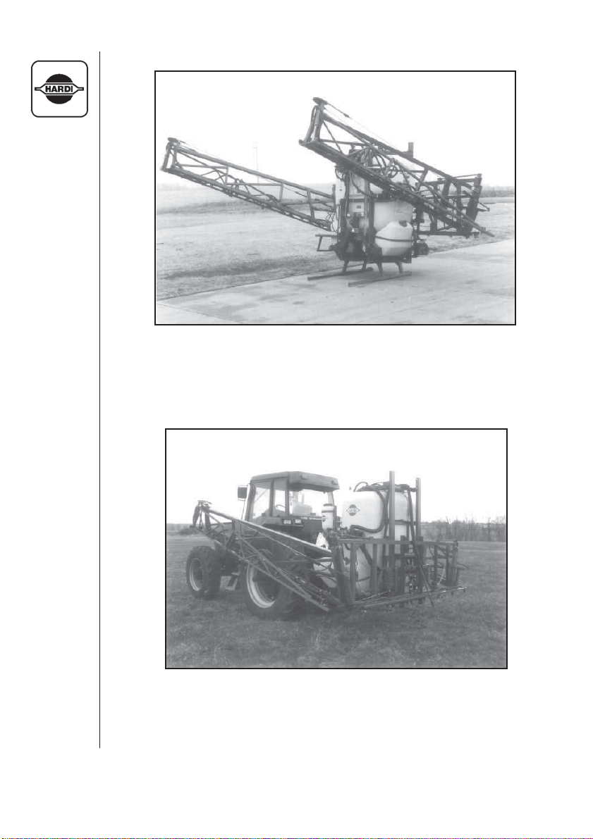
Fig. 1
MEGA 350 W/ 60' EAGLE BOOM
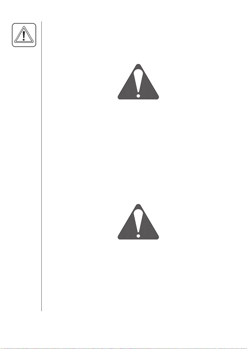
Fig. 2
MEGA 350 W/ 60' EAGLE BOOM
6
HARDI MEGA 230 / 350 CENTRIFUGAL OPERATORS MANUAL
Page 9

1.0 INTRODUCTION
The HARDI MEGA models consist of a pump, frame with a tank that has
either 230 or 350 gallon capacities, ESC-Controls (Electric Control),
Manifold system, P.T.O. shaft and a 60' hydraulic folding Eagle series
spray boom. The 230 gallon model will mount directly to a category II & III
3-point hitch as well as to a category II and category III quick hitch. The
350 gallon model will mount directly to a category III 3-point hitch and
category III & category IIIN quick hitch. A pin kit is available for mounting
the 350 gallon to category II 3-point link arms.
The tank, made of impact-proof and chemical resistant polyethylene, has
a purposeful design with no sharp corners, for easy cleaning. A large,
easy to read tank contents indicator is placed in front of the tank. A step
and platform is placed at the right hand side of the sprayer for easy
access to the tank filling hole.
The ESC (electric control) unit consists of: on/off control valve, pressure
regulating valve, pressure gauge and distribution valves with pressure
equalization feature.
The "Manifold System" features color coded three way valves on suction
and pressure sides of the liquid control system. It allows for safe and
simple use of the sprayer and accessories from one position.
The Self-Cleaning Filter screens out impurities from the spray solution
which are recirculated back to the main tank while clean solution is
constantly being supplied to the boom.
The Eagle hydraulic series boom is available with either 3(HY model) or 5
(HZ model) hydraulic cylinders. The base version being the HY model,
includes boom height adjustment and fold/unfold features all controlled
from the tractor. The HZ model has all the same features as the HY
model but also includes individual wing tilt and fold as added features.
Both versions require single and double acting hydraulic outlets on the
tractor as well as a 12V connection for the HZ model.
HARDI MEGA 230 / 350 CENTRIFUGAL OPERATORS MANUAL
7
Page 10
2.0 SAFETY INFORMATION
WARNING
ALWAYS READ OPERATORS MANUAL BEFORE
USING EQUIPMENT
DO NOT REMOVE ANY SAFETY DEVICES OR
SHIELDS. NEVER SERVICE, CLEAN OR REPAIR A
MACHINE WHILE IT IS OPERATING
WARNING
ALWAYS WATCH FOR THIS SYMBOL TO POINT OUT
IMPORTANT SAFETY PRECAUTIONS
IT MEANS ATTENTION! BECOME ALERT!
YOUR SAFETY IS INVOLVED!
8
HARDI MEGA 230 / 350 CENTRIFUGAL OPERATORS MANUAL
Page 11

RECOGNIZE SAFETY INFORMATION
This is the Safety-alert symbol. When you see
this symbol on your machine or in this manual,
be alert to the potential for personal injury.
Follow recommended precautions and safe
operating practices.
2.1 Follow Safety Instructions
- Carefully read all the safety messages in this manual and the safety
labels fitted to the machine. Keep safety labels in good condition.
Replace missing or damaged safety labels. Be sure that new
equipment components include any current safety labels. Replacement
safety labels are available from your authorized HARDI dealer.
- Learn how to operate the sprayer and how to use the controls prop
erly. Do not let anyone operate the sprayer without proper
instructions.
- Keep your sprayer in proper working condition. Unauthorized
modifications or use may impair the function and/or safety and affect
the machines life.
- If you do not understand any part of this manual and need assistance,
please contact your authorized HARDI dealer.
2.2 Operating The Sprayer Safely
1.Read the complete manual carefully and become familiar with the
operation of the equipment before initial operation in each spraying
season. Failure to do so may result in possible over or under
application of spray solution which may drastically affect crop
production and/or lead to personal injury.
2. Before starting the engine on the tractor unit, be sure all operating
controls are in the off or neutral position, including but not limited to the
P.T.O. shaft and/or spray controls. Be sure the tractor power train is
disengaged.
3.Operate spray and boom functions only when seated in the Operator’s
seat.
HARDI MEGA 230 / 350 CENTRIFUGAL OPERATORS MANUAL
9
Page 12

2.2 Operating The Sprayer Safely (cont'd)
4. One of the most frequent causes of personal injury or death results
from persons falling off or being run over. Do not permit others to
ride on or in. Only one person - the operator - should be in the
tractor when in operation.
5. Before leaving the tractor seat, stop the engine, put all controls in
neutral, and put the transmission control lever in the park position or
neutral with the brakes locked. Read the tractor operations manual for
added safety precautions.
6. PTO driven equipment can cause serious injury. Before working on or
near the P.T.O. shaft, servicing or cleaning the equipment, put PTO
lever in the DISENGAGE position and stop the engine.
7. Do not fold or unfold boom near overhead wires. Serious injury or
death could result if contact is made with electric wires.
8. Keep hands, feet & clothing away from moving parts.
9. Wear relatively tight and belted clothing to prevent from being caught
on some part of the machine.
10
10. Slow down when turning especially with boom extended.
11. Always keep children away from your sprayer and/or tractor unit.
12. Before transporting the sprayer ensure that the boom is fully folded
and fully locked into transport position. Ensure all locking
devices are fully engaged whether hydraulic or mechanical.
13. Slow moving tractors and spray equipment can create a hazard when
on public roads. Avoid personal injury or death resulting from any
accidents by using flashing lights. Local regulations may require
installation of flashing warning lights.
14. Avoid injuries from high pressure fluids penetrating the skin by
relieving system pressure before disconnecting hydraulics or other
lines. Ensure all fittings are tight before applying pressure to the
system.
HARDI MEGA 230 / 350 CENTRIFUGAL OPERATORS MANUAL
Page 13

2.2 Operating The Sprayer Safely (cont'd)
15. Understand service procedures before undertaking any
maintenance. Never lubricate, service, or adjust the machine while
its moving. Securely support any components before working on
them.
16. Keep all parts in good condition and properly installed. Fix damaged
parts immediately. Replace worn or broken parts. Remove excessive
buildup of grease, oil, or debri.
2.3 Handling Chemical Products Safely
1. Direct exposure to hazardous chemicals can cause serious injury.
These chemicals can include lubricants, coolants, paints, adhesives
and agricultural chemicals. Material safety data sheets (M.S.D.S.) are
available for all hazardous chemicals which inform the user of specific
details including, physical and health hazards, safety procedures, and
emergency response techniques.
2. Protective clothing such as rubber gloves, goggles, coveralls and
respirator must be worn while handling chemicals. All protective
clothing should be kept in excellent condition and cleaned regularly or
discarded.
3. If chemicals come in contact with any exposed skin areas, wash
immediately with clean water and detergent. Never place nozzle tips
or any other components that have been exposed to chemicals to lips
to blow out obstructions. Use a soft brush to clean spray nozzles.
4. Dedicate an area to fill, flush, calibrate and decontaminate sprayer
where chemicals will not drift or run off to contaminate people,
animals, vegetation, water supply, etc. Locate this area where there is
virtually no chance of children being in contact with this residue.
5. Decontaminate equipment used in mixing, transferring, and applying
chemicals after use. Follow the instructions on the chemical label for
the correct procedure required. Wash spray residue from outside of
the sprayer to prevent corrosion.
HARDI MEGA 230 / 350 CENTRIFUGAL OPERATORS MANUAL
11
Page 14
2.3 Handling Chemical Products Safely (cont'd)
6. Extreme care should be taken in measuring spray products. Powders
should be used in suitable sized packages or weighed accurately.
Liquids should be poured into a suitable graduated container. Keep
chemical containers low when pouring. Wear a filtered respirator and
let the wind blow away from you to avoid dust and/or splashes
contacting the skin or hair.
7. Store chemicals in a separate, plainly marked locked building. Keep
the chemical in its original container with the label intact.
8. Dispose all empty containers after rinsing in accordance with local
regulations & by-laws. Dispose of all unused chemicals and left over
fertilizer in an approved manner
9. Keep a first aid kit and fire extinguisher available at all times when
handling chemicals.
2.4 Local Poison Information Center
PHONE NO. ____ - ____ - _____
12
Find the phone number for the poison control center in your phone
book and write it in the space above.
Keep a list, in the space provided below, of all the chemicals that you
have in use.
1. ______________
2. ______________
3. ______________
4. ______________
5. ______________
6. ______________
7. ______________
8. ______________
9. ______________
10. _____________
HARDI MEGA 230 / 350 CENTRIFUGAL OPERATORS MANUAL
Page 15

3.0 GLOSSARY
RIGHT HAND and Are determined by facing the forward
LEFT HAND SIDES direction of travel.
FOLDED BOOM Refers to the boom in transport position.
UNFOLDED BOOM Refers to the boom in spray position.
WING Refers to the folding portion of the boom
CENTER Refers to the portion of the boom that
the wings attach to. The wings move up
and down with the center.
INNER WING Refers to the inner portion of the boom.
OUTER WING Refers to the outer portion of the boom.
BREAKAWAY Refers to the device between the inner
wing and the outer wing that allows the
outer wing to swing backward if an
obstacle is encountered.
HARDI MEGA 230 / 350 CENTRIFUGAL OPERATORS MANUAL
13
Page 16
4.0 ASSEMBLING THE MEGA SPRAYER
USE PROPER LIFTING EQUIPMENT
LIFTING HEAVY EQUIPMENT INCORRECTLY CAN CAUSE
PERSONAL INJURY OR MACHINE DAMAGE.
FOLLOW ALL RECOMMENDED PROCEDURES FOR REMOVAL
AND INSTALLATION OF COMPONENTS IN THE MANUAL.
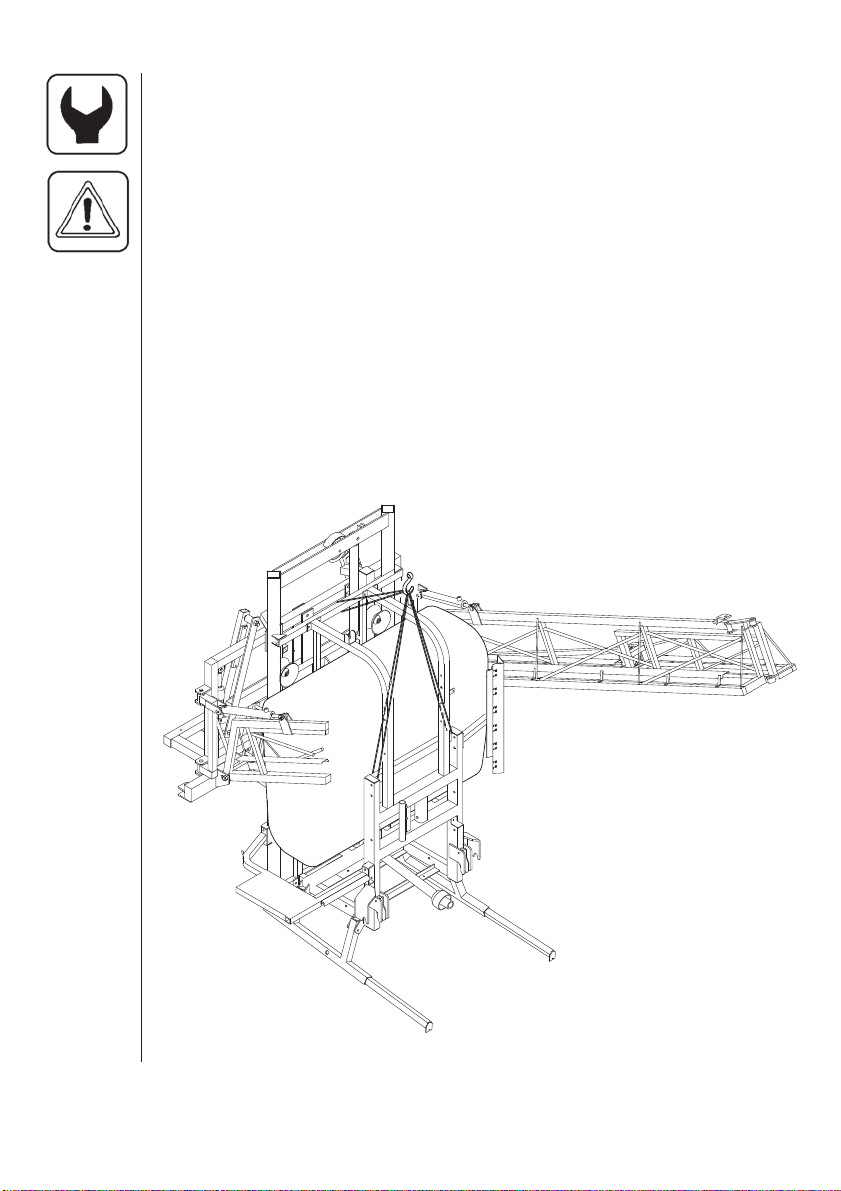
4.1 Lifting Points
When loading or unloading the sprayer from a truck or trailer use the
lifting points as shown.
The Mega Sprayer is shipped in 4 parts for ease of transportation:
1. Tank & frame assembly
2. Wing assembly RH
3. Wing assembly LH
4. Boom mount kit
14
WARNING:
NOTE CORRECT
LOCATION OF SUPPORT LEG
EXTENSIONS.
The Mega tank and frame is
delivered from the factory
with the leg extensions
facing the rear. To move
the extensions to the front of the
Fig. 3
HARDI MEGA 230 / 350 CENTRIFUGAL OPERATORS MANUAL
sprayer (fig.3), remove them
swap the right-hand side with the
left-hand side and refit.
Page 17
4.2 Preparing Wings For Installation
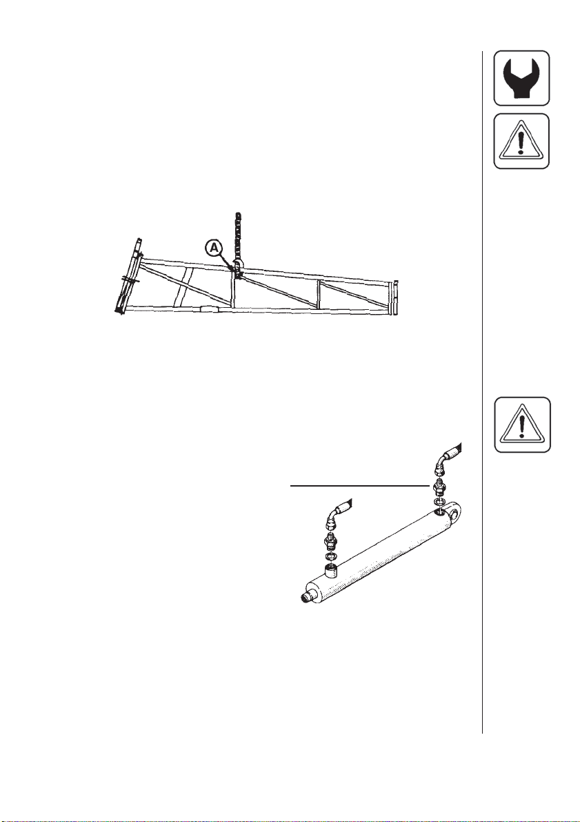
CAUTION: For safe handling, tie inner & outer boom sections
together to prevent accidental unfold during installation.
1. Tie outer boom sections to inner section.
2. Attach lifting chain at lift point (A) on inner boom section. Position
chain between vertical and angled boom members so chain does not
move from this point when boom is lifted.
Fig. 4
4.3 Installing Boom Wings
CAUTION! Before installing wings, ensure that the stands are
lowered and that the leg extensions on Mega frame are extended
forward.
RESTRICTOR
1a. HY BOOM - Fit nut (qty. 1), washers
(qty. 2), to the threaded end of the tie
rod. Fit the rod under tab on mount
plates on center frame. Fit remaining
washers and lock nut to the rods.
Fig.5
1b. HZ BOOM - Attach tilt cylinders to center frame using pins and
cotter pins. Remove plugs from cylinder ports and manually extend
cylinders to their full extension. Install o-ring washers and
restrictor fittings in both ports on hydraulic cylinders. The restrictor
with the small hole is fitted to the fixed (base) end of the hydraulic
cylinder. (Refer to fig. 5)
HARDI MEGA 230 / 350 CENTRIFUGAL OPERATORS MANUAL
15
Page 18
4.3 Installing Boom Wings (cont'd)
2. Position boom hinge on center frame with folded boom sections to
the front.
3. Attach tie rod/tilt cylinder to hinge using pin and cotter pins.
4. Line up lower hinge pin holes and insert pin. Insert threaded pin from
the front through the center frame and hinge and retain with lock nut.
5. Attach safety chain from center section to extended pin on upper
end of hydraulic cylinder - Fit locking ring to pin. This will prevent
boom sections from accidently unfolding during installation. (Refer to
fig. 6)
6. Repeat steps 3-6 for other wing.
7. Attach equalizer cables to inner boom sections using M12x50mm
bolts and lock nuts.
8. Install o-ring washers and restrictor fittings in both ports of hydraulic
fold cylinders. Restrictor with the small hole goes in the fixed (base)
end of the hydraulic cylinder. (Fig. 5)
4.4 Mounting Hydraulic Hoses
BE SURE TO HOOK UP HYDRAULIC LINES PROPERLY!
ENSURE HYDRAULIC LINES HAVE NOT BEEN DAMAGED DURING
SHIPMENT.
16
ESCAPING HYDRAULIC FLUID UNDER PRESSURE CAN
PENETRATE THE SKIN CAUSING SERIOUS INJURY. AVOID THIS
HAZARD BY RELIEVING PRESSURE BEFORE DISCONNECTING
HYDRAULIC LINES.
ENSURE ALL CONNECTIONS ARE TIGHT BEFORE APPLYING
PRESSURE, SEARCH FOR LEAKS WITH A PIECE OF CARDBOARD
NOT YOUR HANDS!
A/ FOLD CYLINDERS
1. Route hydraulic hoses to fold cylinders through the hose support
bracket A (Fig. 6). (Refer to section 11 for hydraulic schematics)
2. Attach hydraulic hoses from right hand side of hydraulic block on
center section to port on the hinge base end of hydraulic fold
cylinders.(Hy Hydraulics Only)
3. Attach hydraulic hoses from left hand side of hydraulic block on
center section to the other port on the hydraulic fold cylinders.(Hy
Hydraulics Only)
HARDI MEGA 230 / 350 CENTRIFUGAL OPERATORS MANUAL
Page 19
4.4 Mounting Hydraulic Hoses (cont'd)
A
Fig.6
4. Disconnect fold cylinder rod (adjustable eye end) from wing section.
5. Ensure cylinder is free of obstruction for retraction and extension.
6. Connect hydraulic hoses to double acting outlet on tractor. (Refer to
section 11 for hydraulic schematics)
7. Start tractor engine and cycle fold cylinders by actuating double
acting outlet 10 times to bleed air from hydraulic system.
8. Stop tractor engine, check hydraulic reservoir oil level and fill as
necessary.
9. Attach fold cylinder rods to boom sections, using previously re moved pins and cotter pins.
B/ TILT CYLINDERS
1. If hydraulic tilt cylinders are fitted to the spray boom, air should be
bled from these lines before spraying.
2. Disconnect tilt cylinder rod eyes from wing section.
HARDI MEGA 230 / 350 CENTRIFUGAL OPERATORS MANUAL
17
Page 20
4.4 Mounting Hydraulic Hoses (cont'd)
Fig. 7
CAUTION! Wing section must be supported before removal of
hydraulic cylinder rod eyes.
3. Ensure cylinder is free of obstruction for retraction and extension.
4. Start tractor engine and cycle tilt cylinder by actuating double acting
outlet 10 times to bleed air from hydraulic cylinders.
18
5. Stop tractor engine, check hydraulic reservoir oil level and fill as
necessary.
6. Reattach tilt cylinder rods to boom sections.
4.5 Installing Center Frame Spray Tube Assembly
1. Attach brackets to center frame using M6x30mm cap screws and lock
nuts.
NOTE: To gain access to mounting holes on the nozzle track,
remove plastic nozzle retaining nuts closest to mount holes
and remove tube as necessary to install cap screws from
the bottom.
2. Attach spray tube assembly using M6x20mm cap screws with lock
nuts on top. The 4 nozzle tube is to be on the right-hand side.
HARDI MEGA 230 / 350 CENTRIFUGAL OPERATORS MANUAL
Page 21
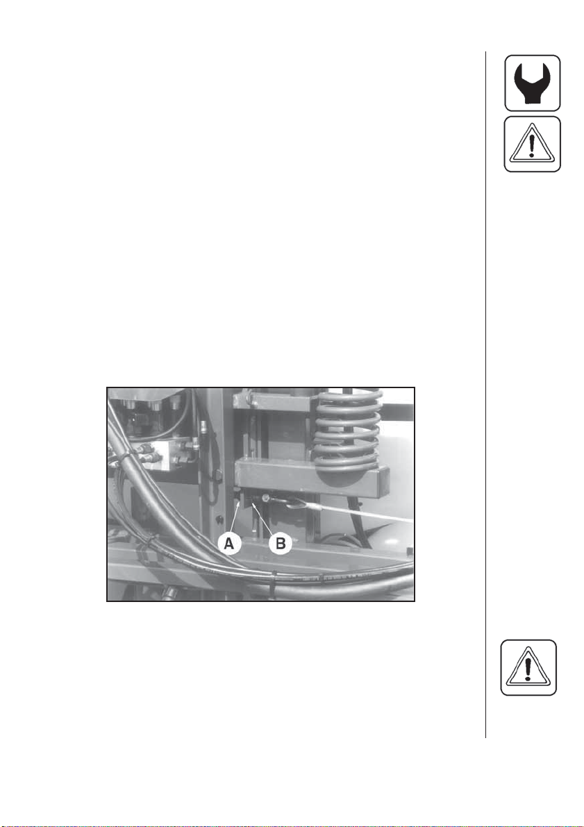
4.6 Adjusting Center Cables
NEVER ATTEMPT TO ADJUST THE CENTER CABLES WITHOUT
HAVING THE BOOM FOLDED ALL THE WAY INTO THE
TRANSPORT POSITION!
The center cables work together to keep the floating frame square to the
stationary frame, while folding the boom in for transport or when spraying
with one side raised and folded.
1. Fold boom into transport position.
2. Shut the tractor off.
3. Check that tilt cylinders are COMPLETELY EXTENDED. Adjust if
necessary.
4. Loosen jam nuts. (B).
Fig. 8
IMPORTANT: Alternate from side-to-side while making
adjustments. Adjust one cable a small amount, and
then the other, to equalize cable tension and maintain
a level center frame.
HARDI MEGA 230 / 350 CENTRIFUGAL OPERATORS MANUAL
19
Page 22
4.6 Adjusting Center Cables (cont'd)
5. Alternating from side-to-side, tighten adjustment nuts (A) so floating
frame is square with stationary frame. Properly adjusted cables will
be very tight and only deflect a small amount (fractions of an inch)
when pulled on by hand.
6. Tighten jam nuts (B).
7. Unfold boom to operating (spraying) position.
8. Fold boom and check that floating frame remains square to stationary
frame.
DO NOT overtighten cables.
4.7 Attaching Feed Hoses - Three Valve System
IMPORTANT: DO NOT use petroleum based lubricants. They will
deteriorate hoses, causing them to weaken and leak.
Lubricate hose ends with liquid dish soap to make
installation easier.
To avoid rework, be sure of fitting locations prior to
attaching hoses. Plastic fittings use a very
aggressive hose barb which makes hose removal
difficult.
20
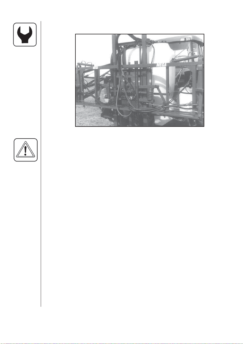
1. Route hoses from each boom section to control valve.
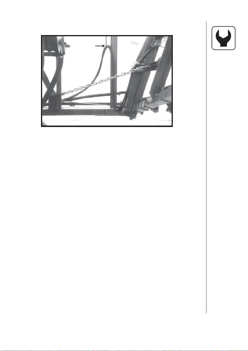
IMPORTANT: Ensure feed hoses have sufficient slack around hinge
to prevent hose binding when boom is folded. Feed
hoses should be routed over the H-frame and
strapped to the support bracket with enough slack to
ensure that there is no binding when boom is
lowered or raised. (Fig. 9)
2. Connect feed hoses to control valves. Right hand feed hose goes to
right hand section control valve.
3. Retain all hoses with tie straps.
HARDI MEGA 230 / 350 CENTRIFUGAL OPERATORS MANUAL
Page 23
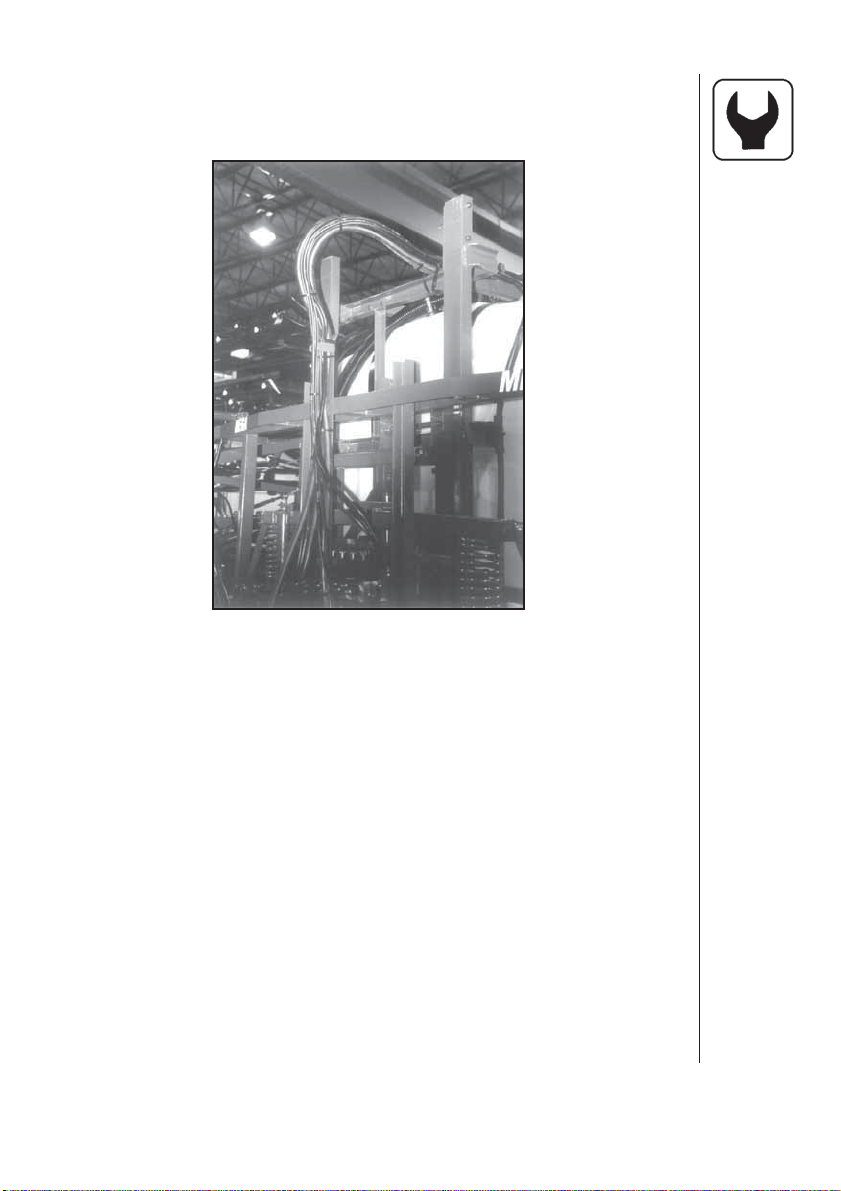
4.7 Attaching Feed Hoses (cont'd)
Fig. 9
4.8 Performing Final Inspection
1. Check hydraulic system for leaks.
2. Check hydraulic hoses for clearance and freedom of movement
throughout entire range of operation.
3.Check feed hoses for freedom of movement through out range of
operation
4. Lubricate all machine lubrication points. (Refer to section 7)
5. Adjust machine for field operation. (Refer to section 8)
6. Ensure all fasteners are tightened correctly.
HARDI MEGA 230 / 350 CENTRIFUGAL OPERATORS MANUAL
21
Page 24
5.0 Mounting The Mega Sprayer
The sprayer is designed for three point mounting on a tractor and will fit
category II & III hitch depending on the sprayer model purchased. The
frame has support legs (for use when the sprayer is free standing) that
can be folded up to minimize crop damage.
Caution!
To
mount
the sprayer
proceed as
follows:
1. Connect lift arms or
quick hitch to sprayer.
2. Lift the sprayer, checking
that no part of the sprayer
contacts the tractor.
3. Adjust the three point lift so the boom
is at 18" to 20" above ground when the
boom lift cylinder is at it's minimum height.
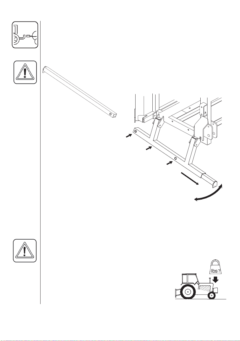
4. Retract the support leg extensions(A) and fold
the legs up under the sprayer frame.
5. Adjust the top link bar so that the sprayer frame and
tank are perpendicular to the ground.
6. Do not connect P.T.O. shaft until operating shaft clearance
has been determined (Refer to section 5.2)
The retractable support legs (F) are spring-loaded, to
avoid injury be careful during folding/unfolding of the support
legs.
E
B
F
C
D
A
Fig. 10
22
WARNING:
OMMENDATION ARE AS FOLLOWS:
Add ballast weights to front of the tractor.
•
Increase tyre pressure if necessary(see tractor
•
instruction book)
Be careful when filling/lifting the sprayer for the
•
first time.
Ensure that any part of the sprayer and tractor
•
do not touch.
Travel at slower speeds when driving with a full
•
tank. (The tractor braking effect will be reduced.)
NOTE THE WEIGHT OF THE SPRAYER. GENERAL REC-
HARDI MEGA 230 / 350 CENTRIFUGAL OPERATORS MANUAL
Page 25

5.1 Dismounting The Mega Sprayer
To dismount the sprayer, proceed as follows:
The retractable support legs must be folded down and extended before
lowering and dismounting the sprayer. Proceed as follows:(fig. 10)
1. Swing support legs down.
2. Push the black button B in.
3. Extend the legs A until the black button clicks out in location hole C.
WARNING!
SIONS
When the boom is folded in transport position the support leg extensions must be placed and extended at the front of the sprayer D.
When the boom is unfolded, the support leg extensions must be placed
and extended at the back of the sprayer E.
4. Lower the sprayer (Be aware of P.T.O. Shaft angle)
5. Disconnect top bar, stop engine and disconnect PTO-shaft, hydraulics
and electric cables.
6. Disconnect lower link arms or remove quick hitch from sprayer.
NOTE CORRECT LOCATION OF SUPPORT LEG EXTEN-
HARDI MEGA 230 / 350 CENTRIFUGAL OPERATORS MANUAL
23
Page 26
5.2 P.T.O. Shaft Operator Safety
WARNING:
ALWAYS STOP ENGINE BEFORE ATTACHING THE
TRANSMISSION SHAFT TO TRACTOR P.T.O. - MOST TRACTOR
P.T.O. SHAFTS CAN BE ROTATED BY HAND TO FACILLITATE
SPLINE ALIGNMENT, WHEN ENGINE IS STOPPED.
When attaching the shaft, make sure that the snap lock is FULLY
ENGAGED - push and pull shaft until it locks.
WARNING:
ROTATING TRANSMISSION SHAFTS WITHOUT PROTECTION GUARDS ARE FATAL.
Always keep protection guards and chains intact and make sure that it
covers all rotating parts, including CV-joints at each end of the shaft.
Do not use without protection guard.
Do not touch or stand on the transmission shaft when it is rotating safety distance: min 5' (1.5 meters).
Prevent protection guards from rotating by attaching the chains allowing sufficient slack for turns.
Make sure that protection guards around tractor P.T.O. and implement
shaft is intact.
Always STOP ENGINE and remove the ignition key before carrying out
maintenance or repairs to the transmission shaft or implement.
5.3 Installation Of P.T.O. Shaft
24
WARNING:
THE P.T.O. SHAFT ANGLE WILL CHANGE CONSIDERABLY WHAN RAISING AND LOWERING THE SPRAYER ON THE 3POINT LINKAGE.
TO PREVENT EXCESSIVE LOADING AND BINDING ON THE P.T.O.
SHAFT, IT MAY BE ADVISABLE TO LEAVE THE P.T.O. SHAFT
DISCONNECTED UNTIL PUMP OPERATION IS REQUIRED.
HARDI MEGA 230 / 350 CENTRIFUGAL OPERATORS MANUAL
Page 27
Initial installation of the shaft is done as follows:
1. Attach sprayer to tractor and set sprayer in the position with short-
est distance between the tractor and sprayer pump P.T.O. shafts.
2. Stop engine and remove ignition key.
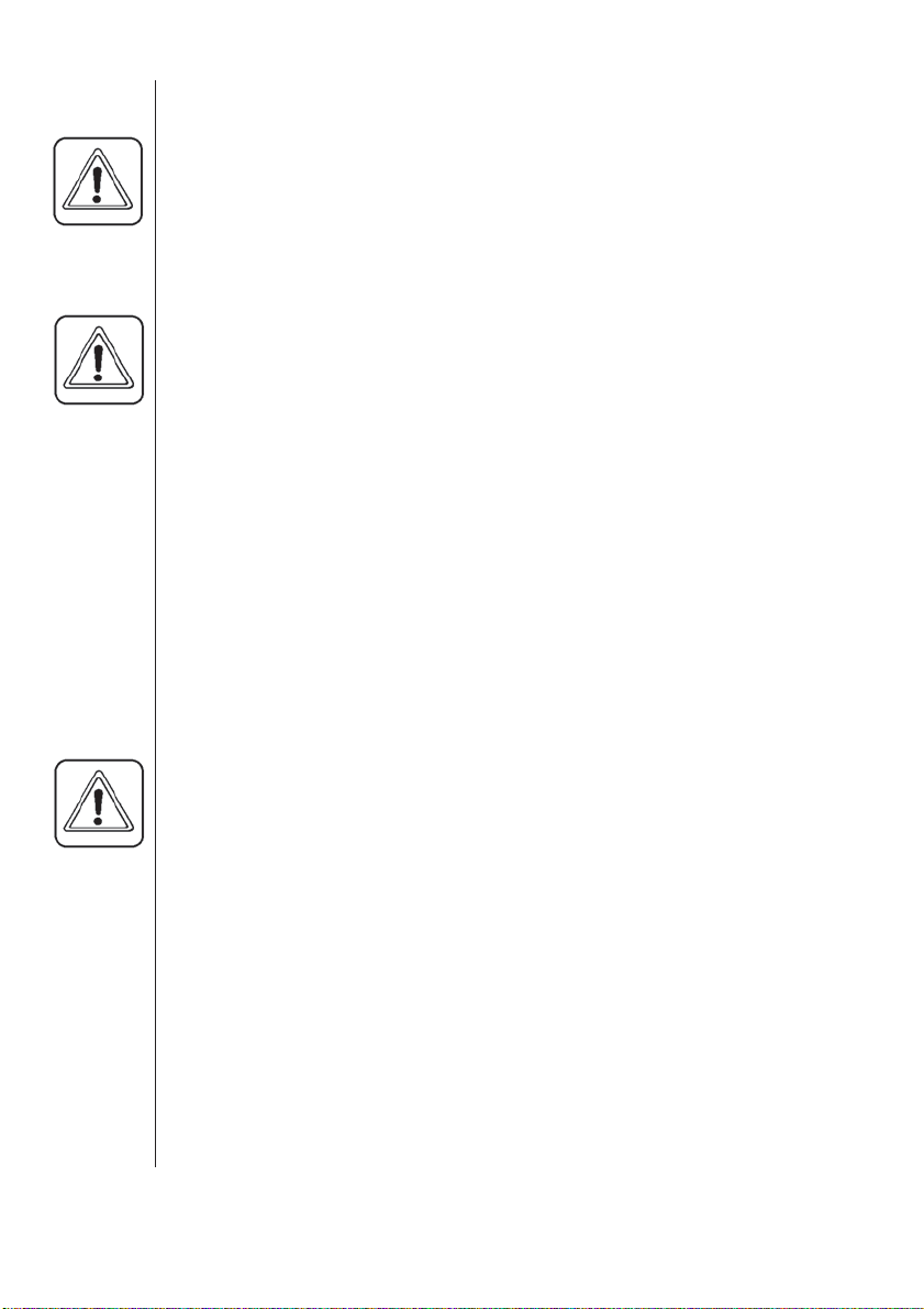
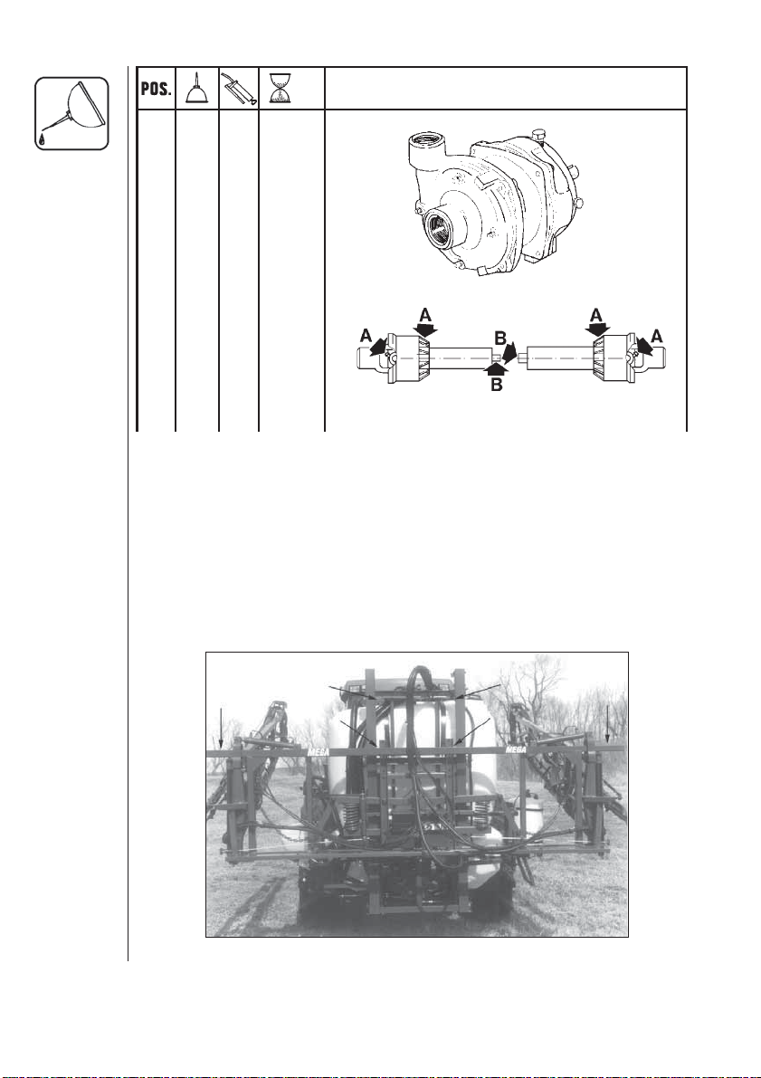
3. If P.T.O. shaft must be shortened, the shaft is pulled apart. Fit the
two shaft parts at tractor and sprayer pump and measure how much
it is necesary to shorten the shaft. Mark the protection guards.
min. 3/4" (20 mm)
Fig. 11
NOTE:
The shaft must always have a minimum overlap of 6"
(150 mm.)
min. 6" (150 mm)
Fig. 12
4. The two parts are shortened equally. Use a saw, and file the profiles
afterwards to remove burrs.
5. Grease the profiles, and assemble male and female parts again.
min. 3/4" (20mm)
Fig. 13
HARDI MEGA 230 / 350 CENTRIFUGAL OPERATORS MANUAL
25
Page 28

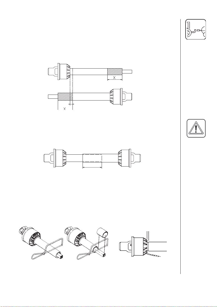
6. Fit the shaft to tractor and sprayer pump.
NOTE: Female part towards tractor.
Fit the chains to prevent the protection guards to rotate with the shaft.
7. To ensure long life of the P.T.O. shaft, try to avoid working angles
greater than 15°.
26
Fig. 14
HARDI MEGA 230 / 350 CENTRIFUGAL OPERATORS MANUAL
Page 29

5.4 Hydraulic Requirements with Eagle Boom
Hydraulic booms need one single outlet for the lift function of the spray
boom and one double outlet for the folding function. Note that the
hydraulic system requires an oil capacity of approximately .8 GPM (3
litres/min.)and a minimum pressure of 1,950 PSI (130 bar).
5.5 Hydraulic Hook-up
BE SURE TO HOOK UP HYDRAULIC LINES PROPERLY!
ENSURE HYDRAULIC LINES HAVE NOT BEEN DAMAGED DURING
SHIPPING.
ESCAPING HYDRAULIC FLUID UNDER PRESSURE CAN
PENETRATE THE SKIN CAUSING SERIOUS INJURY. AVOID THIS
HAZARD BY RELIEVING PRESSURE BEFORE DICONNECTING
HYDRAULIC LINES.
ENSURE ALL CONNECTIONS ARE TIGHT BEFORE APPLYING
PRESSURE, SEARCH FOR LEAKS WITH A PIECE OF CARDBOARD
NOT YOUR HANDS!
IMPROPER HOOK-UP CAN CAUSE DANGEROUS BOOM
MOVEMENTS AND/OR DAMAGE TO THE SPRAYER HYDRAULICS.
DO NOT ALLOW ANYONE NEAR A HYDRAULIC BOOM IN
OPERATION.
ALWAYS SHUT TRACTOR OFF WHEN CONNECTING, SERVICING
OR ADJUSTING BOOM.
1. Attach the heavier (3/8") hydraulic hose for the boom lift to the tractor's
single acting outlet.
2. Attach the lighter (1/4") hydraulic hoses for boom folding & HZ tilt to
the tractor's double acting outlet.
HARDI MEGA 230 / 350 CENTRIFUGAL OPERATORS MANUAL
27
Page 30

5.6 HZ HYDRAULICS
A
FOLD SWITCHES
B
D
TILT SWITCHES
C
E
HYDRAULIC LEVER
ON TRACTOR
F
G
H
Fig. 15
5.7 Installation of Handle
The control handle should be attached to the hydraulic lever that operates the double acting outlet you intend to use. The universal mounting
bracket "E" is very flexible and a number of different mounting positions
can be used.Fig. 15 shows an example of how this may be done.
28
5.8 Electric Hook-up of Handle
1. Connect plug "F" to the tractor's 12 volt power system.
Note: Check with your dealer or tractor operators manual for the best
location to hook up the 12 volt system.
Try to connect the power cable as close as possible to the battery or the
starter of the tractor for a better power supply.
Brown wire on control handle is positive (+).
Blue wire on control handle is negative (-).
2.Connect electric plug "H" from sprayer hydraulics to plug "G" on
handle.
HARDI MEGA 230 / 350 CENTRIFUGAL OPERATORS MANUAL
Page 31

5.9 Control Box for ESC-Controls
The control box for ESC-Controls should be mounted at a convenient
place in the tractor cab. The control box has 4 screw holes in the back
cover, which need to be drilled out for mounting on a flat surface, using
the mount plate, bracket, and hardware furnished with the sprayer.
Power requirement is 12V DC. There should be a 8amp fuse protecting
this circuit. Note polarity.
Brown pos. (+), Blue neg. (-)
Fig. 16
(12-volt junction box for 12-volt hook-up for ESC controls, foam marker,
boom hydraulic controls, etc)
Use the optional HARDI Electric 12 volt outlet box (No. 817925) if more
than one power outlet is required.
HARDI MEGA 230 / 350 CENTRIFUGAL OPERATORS MANUAL
29
Page 32

6.0 OPERATING INSTRUCTIONS
6.1 Filling the Main Tank
Water is filled into the tank by removing the tank lid located at right hand
side of sprayer tank. It is recommended to use water as clean as possible
for spraying purposes. Always fill water through the strainer basket to
prevent foreign particles from entering the tank.
WARNING:
the tank, pointing towards the filling
hole (fig. 17). If the hose is lead into
the tank and the water pressure
drops at the water supply plant,
chemicals may be syphoned back
and contaminate the water supply
lines, plant and well.
Do not let the filling hose enter the tank. Keep it outside
Fig. 17
6.2 Filling the Flush Tanks (if fitted)
Remove the tank lid, fill with clean water and replace lid.
6.3 Standard Sprayer Plumbing Diagram (Shown with
optional Chemical Filler, Flush & RinseTM System and
Agitation shutoff valve)
Review and study the following diagram (Fig. 18). Following the flow
through the system will help you better understand the various functions
of the sprayer system.
30
Fig. 18
HARDI MEGA 230 / 350 CENTRIFUGAL OPERATORS MANUAL
Page 33

6.4 Operating The Mega Boom
ALWAYS OPERATE BOOM ON LEVEL GROUND. BEFORE UNFOLDING THE BOOM ENSURE THAT THE SPRAYER IS HITCHED
TO THE TRACTOR UNIT.
ENSURE THAT THERE ARE NO OBSTRUCTIONS OR PERSONS IN
THE PATH OF TRAVEL BEFORE FOLDING OR UNFOLDING THE
BOOM.
ENSURE THAT THE SAFETY CHAINS ARE FITTED BETWEEN THE
CENTER FRAME AND WING SECTIONS BEFORE TRANSPORTING
AND STORING THE MEGA BOOM.
6.5 Unfolding & Folding The Boom (HY-Hydraulics)
1. Start tractor and bring engine to operating RPM.
2. Activate the single acting outlet to lift the boom.
Note: The boom has a rear transport configured as a hook in the
center of the H-frame. This hook has to be released by lifting the
boom with the single acting outlet until the control arm of the hook
appears between the two flat bars of the hook guide.
Be careful not to bring the control arm past the opening on the hook
guide. See fig. 19
3. Disconnect safety chains from wings.
4. Activate the tractors double acting hydraulic lever to unfold the boom.
Both wings will unfold simultaneously.
5. When boom is completely unfolded, it can
be raised or lowered to desired spray
height by activating the single acting
hydraulic outlet.
6. Before attempting to fold boom back into
transport position, it should be raised all the
way to the top by activating the single acting
outlet.
Note: This time the control arm on the hook
should be raised past the opening of the
hook guide. See fig. 19
HOOK GUIDE
OPENING
HOOK
Fig. 19
7. To fold the boom, actuate the double acting hydraulic lever.
HARDI MEGA 230 / 350 CENTRIFUGAL OPERATORS MANUAL
31
Page 34

When boom has been raised high enough for the control arm to go past
the opening on the hook guide, the wings can be folded into transport
position.
The boom is folded in by activating the double acting outlet. Ensure that
the hook engages on the crossbar on the ‘H-frame’ (rear transport).
8. Reconnect the safety chains from the center section to the wing
sections.
6.6 Unfolding and Folding Boom (HZ-Hydraulics)
1. Depress switches "A" & "B" (See fig. 15) and move hydraulic handle
forward or rearward to activate oil flow.
Switch positions of the hoses in the double acting outlet if the direction
required to activate the boom needs to be reversed.
2. "One side folding" can be achieved by following the above procedure
except that only one of the switches is depressed.
ALWAYS PUT WING IN THE HORIZONTAL POSITION PRIOR TO
FOLDING.
NEVER ATTEMPT TO FOLD BOOM TO TRANSPORT POSITION
WHEN WINGS ARE TILTED. UNEXPECTED BOOM MOVEMENTS
MAY OCCUR IF WINGS ARE TILTED WHEN FOLDING.
32
6.7 Tilting Boom (HZ-Models Only)
1. Depress switch "C" or "D" depending on what side needs to be tilted
and move hydraulic handle forward or rearward to activate oil flow.
HARDI MEGA 230 / 350 CENTRIFUGAL OPERATORS MANUAL
Page 35

6.8 Operation Of The ESC Controls
Fig. 20
1. Adjust screw for constant boom pressure
2. Distribution valve
3. Pressure regulating valve
4. Control unit pressure gauge
5. Pressure filter
Fig. 21
A. Master operating switch for on-off of valves
B. Operating switches for distribution valves
C. Pressure regulating switch (-) lower
D. Pressure regulating switch (+) raise
HARDI MEGA 230 / 350 CENTRIFUGAL OPERATORS MANUAL
33
Page 36

6.8 Operation of the ESC- Controls (cont'd)
(Fig. 20,21)
1. Choose the correct nozzle (Section 6.15). Make sure that all the
nozzles are the same type and capacity.
2. Put the tractor in neutral and adjust the P.T.O. RPM's until the number
of revolutions of the pump corresponds to the intended traveling
speed. Remember the number of revolutions on the P.T.O. must be
kept between 300-600 rpm.
3. Open or close knob 5 depending on whether pressure agitation is
required. (Remember pressure agitation takes 5% to 10% of pump
output).
4. On-off switch A is "ON" against green dot.
5. All distribution valves switch B are also "ON" against green dot.
6. Hold pressure regulating switch C to the (-) until handle 3, stops
rotating, this will be the "minimum pressure" setting.
7. Hold pressure regulating switch D (+) until desired pressure is shown
on the pressure gauge.
Note: Adjust the constant distribution boom pressure one section at a
time as follows: (Start with the valve turned closed before adjusting).
8. Shut-off the first boom distribution valve switch B. (Fig. 21)
34
9. Turn the adjusting screw 1 until the control unit pressure gauge (7)
again shows the same pressure as set in step 6 above. (Turn the
screw clockwise for higher pressure, counterclockwise for lower
pressure).
10. Turn the first boom distribution valve switch B back on.
11. Repeat steps 7 through 9 for the two remaining boom distribution
valves.
Note: Hereafter adjustment of the constant boom pressure will only be
needed if you change to nozzles with other capacities, but not required if
only changing pressure or application rate using the same nozzles.
12. Operating the control unit while driving: In order to shut off the entire
boom activate on-off switch A (Fig. 21). This returns all the pump
outputs to the tank through the return system. The diaphragm antidrip valves ensures instantaneous closing of all nozzles.
HARDI MEGA 230 / 350 CENTRIFUGAL OPERATORS MANUAL
Page 37
In order to shut off one or more sections of the boom, switch one or more
unneeded boom distribution valves B to off position. The constant
pressure device ensures that the pressure does not increase in the
sections which are still operating.
In case of electrical failure it is still possible to manually overide all
functions of the operating unit. To operate manually, disconnect the
multiplug from the ESC control box first and operate the handles by hand.
It is possible to change pressure, turn boom sections on or off, or shut off
the complete control unit manually.
IMPORTANT:
When the sprayer is stored, the EC control box and the
multiplug must be protected against moisture and dirt. A plastic bag
may be used to protect the multiplug. Store the control box in a
clean dry place.
6.9 Agitation Adjustment (Agitation nozzles only)
Agitation is necessary to keep the solution in your tank properly mixed.
Consult your chemical
supplier for the recommended amount of
agitation.
In general, maximum
agitation is required but
some products tend to
foam easily. To reduce
foaming in some instances
anti-foaming agents
may be added to the
tank (Refer to chemical
label). When running
low liquid levels in the tank, agitation may be reduced to facilitate pump
priming and avoid pressure fluctuations. Make sure that you have adjusted the agitation properly before sprayer calibration.
Fig. 22
Turning the Agitation Valve A clockwise will reduce the agitation flow.
Turning the valve counter clockwise will increase the agitation flow.
HARDI MEGA 230 / 350 CENTRIFUGAL OPERATORS MANUAL
35
Page 38

6.10 Manifold System
Pressure Manifold
Suction Manifold
Fig. 23
Standard Manifold Fittings
The "Manifold System" is located at the left hand side of the sprayer
permitting operation of most of the (fitted) accessories from one position.
The modular design of the Manifold system allows the easy addition of
many accessories to the plumbing system of the sprayer. The system can
be expanded to a maximum of 4 valves on the pressure side and 2
valves on the suction side. The system can also be fitted with an agitation
bypass valve which ensures more complete drainage of the sprayer
before cleaning or refilling.
The Manifold valve faces are colored discs for easy identification. The
green face identifies the pressure manifold, the black disc identifies the
suction manifold and a blue disc indicates the agitation bypass valve
when fitted.
The green pressure valves and the black suction valves have 4 positions.
Two positions are for options indicating that the valve will be open in this
position. The other two are marked “O” indicating that the valve is closed.
The blue return valve only has 2 positions. The arrow on the handle
indicates which position is selected.
36
Symbols are fitted to the faces of the 3 way valves indicating direction of
flow of the liquid.
An explanation of the symbols is as follows:
HARDI MEGA 230 / 350 CENTRIFUGAL OPERATORS MANUAL
Page 39

6.10 Manifold System (cont'd)
Green Disk= Pressure Valve
• TO ESC Control • To Tank Rinse
nozzle
• To Chemical Filler
Black Disk= Suction Valve
• From Flush
Tank
Blue Disk= Agitation Bypass Valve
• Return to
Pump
• To Hose reel
/spray gun
• From Main tank
• Return to Tank
HARDI MEGA 230 / 350 CENTRIFUGAL OPERATORS MANUAL
37
Page 40

6.11 Manifold System Operating Instructions
For normal operation of the sprayer the first pressure manifold valve A
handle is turned toward the ESC control symbol and the suction manifold
valve B handle is turned toward the main tank symbol. On a standard
Manifold system these will be the only symbols fitted on the valves.
When accessories are fitted (i.e. chemical filler, Flush & Rinse
TM
etc.)
operation of these accessories is achieved by turning the relevant valve
handle to the required symbol. All the other handles on the same
manifold must be turned to the off-position (handle placed horizontal).
Example:
To operate Chemical Filler
1. Ensure other pressure manifold valves are in the off position.
2. Turn handle of pressure manifold valve from ESC control symbol to
Chemical Filler symbol. This directs flow of liquid from Pump to
the Chemical Filler.
3. Operate the Chemical Filler as per pages 16 & 17 in the HARDI-
Chemical Filler Operators Manual.
4. Return the pressure manifold valve to it's previous position on
completion of use of Chemical Filler.
Note: If all the pressure valves are closed, the safety valve will open
inside the tank.
38
Fig. 24
HARDI MEGA 230 / 350 CENTRIFUGAL OPERATORS MANUAL
Page 41

6.12 Agitation Bypass Valve Operation (Optional)
The optional agitation bypass valve is fitted when it is desired to cut the
by-pass liquid to the tank at low tank levels and achieve more complete
drainage of the tank. The by-passed liquid is directed back to the suction
manifold and therefore is recirculated back through the pump.
This valve, when fitted, must have the handle positioned in either
the "Tank" position or the "Pump" position. There is no "Off"
position indicated on this valve.
Fig. 25
6.13 Operation of the Tank Drain Valve
WARNING: BEFORE USING THE TOP DRAIN VERIFY THAT DISPOSAL OF WASTE IS DONE ACCORDING TO CHEMICAL LABEL
INSTRUCTIONS AND LOCAL REGULATIONS.
The tank is drained through the suction manifold valves on the lower left
hand side of the tank frame.
To drain the tank proceed as follows:
1. Ensure that the handle on the valve under the tank is turned to a
horizontal position with the arrow on the handle facing up.(Fig. 26)
2. Ensure that the handle on the suction manifold valve is placed in a
vertical position.
HARDI MEGA 230 / 350 CENTRIFUGAL OPERATORS MANUAL
39
Page 42
6.13 Operation of the Tank Drain Valve (cont'd)
3. Remove the stain less steel fork that
retains the 90°hose
fitting to the bottom
of the tee piece on
the suction mani fold.
4. Remove the 90°
hose fitting from
the valve. (Fig. 27)
5. Turn the valve
handle on the
valve under the
tank back to a
horizontal position.
WARNING: WEAR PROTECTIVE CLOTHING WHEN SERVICING AND
HANDLING COMPONENTS THAT HAVE BEEN IN CONTACT WITH
SPRAY LIQUID.
6. Turn the handle on
the suction mani fold valve back so
that the arrow on
the handle is fac ing the symbol for
the main tank.
Fig. 26
40
7. The tank will now
drain. Be aware of
splashing. If drain ing residues (eg.
liquid fertilizer) into
a reservoir, a
coupler with hose can rapidly be connected to the suction manifold tee
piece and the liquid safely drained.
HARDI MEGA 230 / 350 CENTRIFUGAL OPERATORS MANUAL
Fig. 27
Page 43

6.14 Nozzle Selection
Correct selection of nozzle and calibration of the sprayer are critical to
achieve accurate and cost effective use of farm crop protection products.
Your HARDI sprayer has been supplied with 110° flat spray Green Color
Tips™ that will apply approximately 20 U.S. GPA at 30 PSI and 5 MPH.
The 110° flat spray nozzle was chosen rather than the 80 degree nozzle
for two reasons: 1- It may be used at a lower minimum height which
reduces the risk of wind drift; 2- It's greater overlap permits better uniformity of spray distribution, particularly if boom height varies on rough
ground. Normal boom height setting with 110° nozzles is 18" to 20" above
the crop or weeds, whichever is taller.
Should you wish a different application rate or different type of nozzle,
HARDI manufactures a nozzle for virtually every need.Refer to the Hardi
Nozzle Catalog for the complete range of Hardi Nozzles.
ALWAYS CONSULT YOUR CHEMICAL SUPPLIER FOR RECOMMENDED CHEMICAL RATE AND WATER APPLICATION RATE.
ALWAYS WEAR PROTECTIVE GLOVES WHEN HANDLING
NOZZLES.
The following tables show what types of spray nozzles are suitable for
different applications. Refer to the HARDI nozzle catalogue to find the
coorrect nozzle for each spraying application.
COLOR TIPS™ 110 degree flat
fan,one piece cap and nozzle;
color coded for flow rate selection.
For herbicides, insecticides, and
fertilizer applications. 50, 80, and
100 mesh screens are normally
used.
FLAT SPRAY NOZZLES in 65
degree, 80 degree, and 110
degree spray angles. For
herbicides, insecticides, and
fertilizer applications. 50, 80, and
100 mesh screens are normally
used.
HARDI MEGA 230 / 350 CENTRIFUGAL OPERATORS MANUAL
S4110
4665-65 degree
2080-80 degree
4110-110 degree
41
Page 44

6.14 Nozzle Selection (cont'd)
FLOOD NOZZLES set at 40"
spacing. Designed for high
volume application.
HOLLOW CONE NOZZLES for
high pressure and high volume
insecticide application in row
crops. 1553 nozzles are ALWAYS
used with swirl plates shown
below EXCEPT when used as
solid stream nozzles. 50,80, or
100 mesh screens are normally
used with these nozzles.
SWIRL PLATE used in
conjunction with cone nozzle to
create desired spray pattern.
These swirls work with 1553
series cone nozzles. Grey, blue,
or black swirls are used to create
hollow cone effect. White swirls
are used to create full cone effect.
HOLLOW CONE CERAMIC
NOZZLES for high pressure and
high volume fungicide and
insecticide application.
4598
1553
Must add swirl to
produce hollow
cone pattern
Grey
Blue
Black
White
1299
42
LARGE DROPLET HOLLOW
CONE NOZZLE for use where
drift must be kept to a minimum.
These nozzles must always be
fitted with 1553 nozzles and grey
swirl plates. 50,80 or 100 mesh
screens are normally used with
these nozzles.
HARDI MEGA 230 / 350 CENTRIFUGAL OPERATORS MANUAL
371077
Page 45

6.14 Nozzle Selection (cont'd)
LARGE DROPLET FLAT SPRAY
TIP IN 150 DEGREE SPRAY
ANGLE. Always used in
conjunction with 1553-14-16-18 or
20 cone nozzle. 50,80 or 100
mesh screens are normally used
with these nozzles.
SOLID STREAM NOZZLE for high
volume liquid fertilizer application.
In this application, the 1553
nozzle is always used with
330013 o-ring and 50,80 or 100
mesh screens.
3-HOLE NOZZLE-SYNTAL/
CERAMIC this nozzle disperses
the spray liquid in three solid
streams, thereby reducing the
number of plants at risk of
scorching by the application of
liquid fertilizer.
371551
1553 less swirl
371537
thru
371543
HARDI MEGA 230 / 350 CENTRIFUGAL OPERATORS MANUAL
43
Page 46

6.15 Calibration
WARNING: ALWAYS CALIBRATE YOUR SPRAYER WITH CLEAN
WATER ONLY! IN ADDITION, WEAR PROTECTIVE
CLOTHING WHEN CALIBRATING YOUR SPRAYER!
Why must you calibrate a sprayer?
A nozzle selection chart will tell you what application rate you should
expect. Variations due to nozzle wear, errors in pressure adjustment, and
tractor speedometer can result in a possible error in application rate.
How do you calibrate a sprayer?
Calibration kits are available from HARDI, #818103 for US gallons &
#818104 for metric calibration.
Following are some tips to remember when using the calibration kit
method:
• When determining the length of time required to drive the recommended distance, drive in actual field conditions with a half-full tank.
• Repeat the test several times, each time avoiding the tracks from the
previous test. Take the average of the times recorded.
• Calibration of the sprayer should be completed at the beginning of the
season and repeated after every 2 to 3 full days of spraying, and every
time you change volume rate or use new nozzles.
44
• Before you calibrate, check the flow of each nozzle. If it puts out more
than 10% of its original volume, replace it.
HARDI MEGA 230 / 350 CENTRIFUGAL OPERATORS MANUAL
Page 47

6.15 Calibration (cont'd)
Select your calibration method- Ounce method or Formula method.
Then follow the steps described below:
Ounce Method
1. Determine how long it takes you to cover the test strip.
Use the following chart to determine the length of your test strip.
Row width for broadcast application is equal to your nozzle spacing.
For your drop nozzle or band application, use row spacing.
Row width or nozzle spacing (in.) Distance (ft.)
40 102
38 107
36 113
34 120
32 127
30 136
28 146
26 157
24 170
22 185
20 204
18 227
16 255
14 291
2. Measure the amount of time it takes you to travel the test strip when
throttle is set at spraying speed.
3. In a container (with oz. measurements), catch the spray from one
nozzle for that amount of time. For drop or band nozzles, catch the
spray from all nozzles for the row.
4. Read the ounces in the container. That is the actual GPA applied.
(ounces - GPA)
HARDI MEGA 230 / 350 CENTRIFUGAL OPERATORS MANUAL
45
Page 48

6.15 Calibration (cont'd)
Formula Method
1. Check your spraying speed.
Measure a test strip of at least 200 feet (300 feet is ideal). Travel the
distance at the speed you plan on spraying and record the time it takes
to travel the distance. Read from the chart or use the formula to find
your exact travel speed.
Formula:
distance (ft.) x 0.68
seconds
= MPH
Speed in MPH 200 ft. 300 ft.
3.0 45 68
3.5 39 58
4.0 34 51
4.5 30 45
5.0 27 41
6.0 23 34
7.0 19 29
7.5 18 27
8.0 17 26
9.0 15 23
2. Calculate the required nozzle output. Use either the nozzle wheel (if
nozzle spacing is 20 inches), or this formula:
Travel Time (in seconds)
46
Formula:
GPM =
GPA x MPH x W (in.)
5940
Formula:
GPM =
10 x 7 x 20
5940
= .24 GPM
Note: W= • Nozzle spacing (in inches) for broadcast
application.
• Row spacing (in inches) divided by number of
nozzles per row for drop nozzle application.
• Sprayed band width or swath width (in inches)
for band application divided by number of nozzles
per band.
• Note that on the nozzle wheel, W = 20 inches.
3. Set correct pressure.
Read the required pressure from the nozzle table in the nozzle
catalogue or nozzle wheel. With clean water in the tank and line, turn
on the sprayer and set the target pressure. Collect the spray from one
nozzle for one minute in a container. Adjust pressure until you collect
the precise GPM called for.
HARDI MEGA 230 / 350 CENTRIFUGAL OPERATORS MANUAL
Page 49

6.15 Calibration (cont'd)
Calibration for carriers other than water
Use the following water rate conversion chart to determine the right
conversion factor. When you've determined the new converted GPM or
GPA, you can follow the steps on either the pressure or ounce method of
calibration.
Weight of solution Specific Gravity Conversion Factors
7.00 lbs/gal .84 .92
8.00 lbs/gal .96 .98
8.34 lbs/gal-water 1.00 1.00
9.00 lbs/gal 1.08 1.04
10.00 lbs/gal 1.20 1.10
10.65 lbs/gal-28% N 1.28 1.13
11.00 lbs/gal 1.32 1.15
12.00 lbs/gal 1.44 1.20
14.00 lbs/gal 1.68 1.30
Example: 20 GPA of 28% N
Then GPA (solution) x conversion factor = GPA (water)
20 GPA (28% N) x 1.13 = 22.6 GPA (water)
Calibrate for 22.6 GPA of water
For conversion to Imperial gallons per acre, multiply U.S. GPA by .833
For conversion to liters per hectare, multiply U.S. GPA by 9.34
For conversion to liters per acre, multiply U.S. GPA by 3.78
Formula for tractor speed:
Distance (in feet) x .682 = MPH
Second
HARDI MEGA 230 / 350 CENTRIFUGAL OPERATORS MANUAL
47
Page 50

7.0 MAINTENANCE
ALWAYS CLEAN BOOM AT THE END OF YOUR WORKDAY OR
BEFORE SERVICING IS DONE TO AVOID UNNECESSARY CONTACT
WITH CHEMICALS.
In order to derive full benefit from the sprayer for many years the following few but important rules should be kept:
7.1 Cleaning the Sprayer
Guidelines
Read the whole label of the chemical. Take note of any particular instructions regarding recommended protective clothing, deactivating agents,
etc. Read the detergent and deactivating agent labels. If cleaning procedures are given, follow them closely.
Be familiar with local legislation regarding disposal of pesticides
washings, mandatory decontamination methods, etc. Contact the appropriate body, eg. Dept of Agriculture.
Cleaning starts with the calibration, as a well calibrated sprayer will ensure the minimal amount of remaining spray liquid.
It is good practice to clean the sprayer immediately after use thereby
rendering the sprayer safe and ready for the next pesticide application.
This also prolongs the life of the components.
48
It is sometimes necessary to leave spray liquid in the tank for short periods, eg. overnight, or until the weather becomes suitable for spraying
again. Unauthorized persons and animals must not have access to the
sprayer under these circumstances.
The Hardi Flush & Rinse
TM
system is available for the Mega sprayer that
offers both the flushing of internal components and also a highly effective
internal rinsing system of the sprayer tank.
If the product applied is corrosive, it is recommended to coat all metal
parts of the sprayer before and after use with a suitable rust inhibitor.
Remember: Clean sprayers are safe sprayers.
Clean sprayers are ready for action.
Clean sprayers can not be damaged by pesticides and their
solvents.
HARDI MEGA 230 / 350 CENTRIFUGAL OPERATORS MANUAL
Page 51

Cleaning
1. Dilute remaining spray liquid in the tank with at least 10 parts water
and spray the liquid out in the field you have just sprayed.
NOTE: It is advisable to increase the forward speed (double if pos-
sible) and reduce the pressure. For S4110 nozzles, pressure
may be reduced to 22psi (1.5 bar).
2. Select and use the appropriate protective clothing. Select detergent
suitable for cleaning and suitable deactivating agents if necessary.
3. Rinse and clean sprayer and tractor externally. Use detergent if necessary.
4. Remove tank and suction filters and clean. Be careful not to damage
the mesh. Replace suction filter top. Replace filters when the sprayer
is completely clean.
5. With the pump running, rinse the inside of the tank. Remember the
tank roof. Rinse and operate all components and any equipment that
has been in contact with the chemical.
6. After spraying the liquid out again in the field, stop the pump and fill at
least 1/5 of the tank with clean water. Note that some chemicals require the tank to be completely filled. Add appropriate detergent and/
or deactivating agent, eg. Washing soda or Triple ammonia.
NOTE: If a cleaning procedure is given on the chemical label, follow
it closely.
7. Start the pump and operate all controls enabling the liquid to come in
contact with all the components. Leave the distribution valves until last.
Some detergents and deactivating agents work best if left in the tank
for a short period. Check the label.
8. Drain the tank and let pump run dry. Rinse inside of tank, again letting
the pump run dry.
9. Stop the pump. If the pesticides used have a tendency to block nozzles
and filters, remove and clean them now.
10. Replace all the filters and nozzles and store the sprayer. If, from
previous experiences, it is noted that the solvents in the pesticide are
particularly aggressive, store the sprayer with the tank lid open.
NOTE: If the sprayer is cleaned with a high pressure cleaner we
recommend lubrication of the entire machine.
HARDI MEGA 230 / 350 CENTRIFUGAL OPERATORS MANUAL
49
Page 52

7.2 Filters
WARNING:
components that have been in contact with spray liquid.
Clean filters ensure :
Sprayer components such as valves, diaphragms and operating unit
•
are not hindered or damaged during operation.
Nozzle blockages do not occur while spraying.
•
Long life of pump. A blocked suction filter will result in pump cavit-
•
ation.
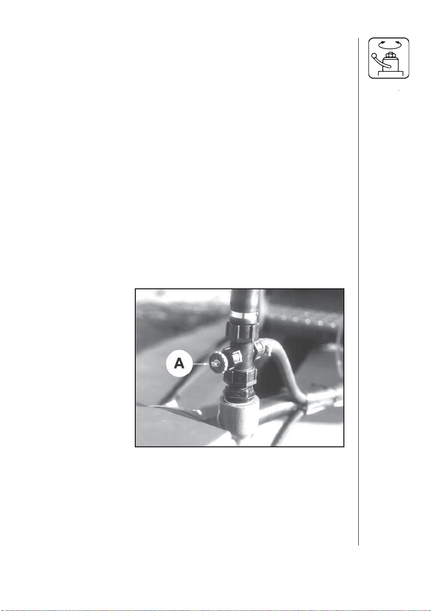
Suction filter
The optional suction filter is
located at the back of the
pump, check it regularly.
Ensure the o-ring A (fig. 17)
on the filter housing and it is
in good condition and
lubricated.
Wear protective clothing when servicing & handling
Fig. 28
50
Suction FilterNozzle Size
Pressure Filter
80
60
100
40
150
20
PSI
0
200
H A R D I
Lilac (08)
Brown (10)
Yellow (12)
50
100
Orange (14)
Red (16)
White (18)
Green (20)
& Larger
50
30*
80
50*
Fig. 29
* Standard Equipment
HARDI MEGA 230 / 350 CENTRIFUGAL OPERATORS MANUAL
Nozzle Screen
100
80
50*
Page 53

7.3 Lubrication
Recommended lubrication is shown in following tables.
Use ball bearing grease (lithium grease No. 2)
Note: If the sprayer is cleaned with a high pressure cleaner or
fertilizer has been used, we recommend lubrication of all sections.
Position on
sprayer
Oil
Grease
Operation
hours
Fig. 30
Mega 350
HARDI MEGA 230 / 350 CENTRIFUGAL OPERATORS MANUAL
51
Page 54
X 1000
AX8
BX40
7.4 Greasing the H-Frame and Center Frame
Every 8 hours new grease should be applied to the wear surfaces on the
H-frame and center frame.
Every 50 hours the grease on the H-frame and center frame should be
completely cleaned off with a degreasing solvent and new grease
applied.
52
Fig. 31
HARDI MEGA 230 / 350 CENTRIFUGAL OPERATORS MANUAL
Page 55

7.5 Greasing the Boom
Every 10 hours the grease zerts indicated in the following pictures
should be greased.
Fig. 32
Fig. 33
HARDI MEGA 230 / 350 CENTRIFUGAL OPERATORS MANUAL
53
Page 56

7.6Lubrication of Chain and Sprocket
Every 25 hours the chain and sprocket at the hinge point of the intermediate and outer wing sections should be lubricated with a chain lubricant.
7.7 Greasing the Breakaway Clutch
NEVER PLACE FINGERS INTO OPEN BREAKAWAY CLUTCH OR
YOU MAY BE INJURED SHOULD CLUTCH SNAP CLOSED.
1. Unfold the boom into spray position.
2. Standing in front of the outer wing, snap the breakaway open by
quickly pushing the boom away from you.
3. With the two clutches opened up, stick the nozzle of grease gun into
the clutch and apply a generous amount of grease. This should be
done every 8 hours. (Refer to fig. 34)
4. Apply oil to top of breakaway section hinge to lubricate bushing.
A. RETORQUE FASTENERS
40 Hrs
40 ft/lbs
55 N•m
B. GREASE
8 Hrs
A
B
105192
54
Fig. 34
HARDI MEGA 230 / 350 CENTRIFUGAL OPERATORS MANUAL
Page 57

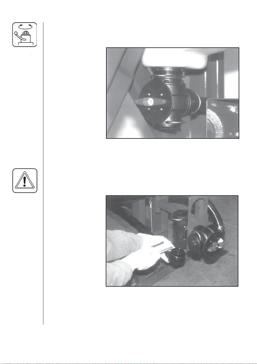
7.8 Maintenance of Triplets (When Fitted)
Every 40 hours the triplets should be disassembled removed and
cleaned. This is done by pulling out the stainless clip on the side of the
triplet assembly.
Clean the bottom part as well as the top part throughly.
Coat o-ring surface with a light film of vegetable oil, if unit is to be stored
for a long period of time.
If the triplets are not cleaned regularly they may become hard to turn,
with possible damage to them as a result.
Fig. 35
WARNING:NEVER SERVICE YOUR CONTAMINATED NOZZLES
WITHOUT WEARING CHEMICAL RESISTANT GLOVES AND
SAFETY GOGGLES.
HARDI MEGA 230 / 350 CENTRIFUGAL OPERATORS MANUAL
55
Page 58

8.0 ADJUSTMENTS
HARDI CANNOT ASSUME RESPONSIBILITY OR BE HELD LIABLE
FOR ANY LOSS OR DAMAGE THAT OCCURS DUE TO LACK OF
ADJUSTMENTS OR MAINTENANCE.
WE URGE YOU TO FOLLOW THE ADJUSTMENT AND
MAINTENANCE RECOMMENDATIONS FOR EVERYONES SAFETY.
MAKE IT A DAILY HABIT TO INSPECT YOUR BOOM FOR NEED OF
ADJUSTMENT OR MAINTENANCE.
IMMEDIATELY REPLACE ANY PARTS ON THE BOOM THAT ARE
WORN OR BROKEN.
ALWAYS CLEAN YOUR BOOM BEFORE ADJUSTING IT TO AVOID
UNNECCESARY CONTACT WITH CHEMICALS.
The boom wing sections on the Mega Sprayer have been preassembled,
adjusted and tested in the factory. The boom however, will require
additional adjustments shortly after being taken into use (10 hours) and
thereafter at a minimum an annual basis to perform at its maximum
levels.
56
To further insure the booms proper performance, the Mega boom also
has to be maintained on a regular basis. Please follow the suggested
maintenance intervals.
Perform the adjustment procedures in the same sequence as they are
written in this manual.
8.1 Adjustment and Maintenance Intervals
IMPORTANT: To maximize boom life and performance, retighten all
boom fasteners and inspect boom for proper adjustment
after the first 10 hours of use.
Lubricating of the boom should be done daily to ensure
maximum performance and life.(Refer to maintenance
section 7)
HARDI MEGA 230 / 350 CENTRIFUGAL OPERATORS MANUAL
Page 59

8.2 Checking and Adjusting Sprocket Timing
1. With boom unfolded in the working position, check to ensure that the
seventh pin connection (A) in the timing chain is aligned with the
center line between the sprocket cap screws (B).
2. To adjust timing, loosen turnbuckles on the front and rear cables until
slack.
3. Standing on the front side of the boom, position the seventh pin (A) of
the timing chain on the sprocket as indicated in step 1.
4. Adjust front and rear cable tension. (Refer to sections 8.5 & 8.10)
A
B
Fig. 36
8.3 Aligning Wing Assemblies
(Fig. 37)
1. With boom unfolded and in the working position, check alignment of
the intermediate section with the center frame.
2. With fold cylinder pressurized, determine if the intermediate section
needs to be adjusted to the front or rear to come into alignment with
center frame.
NOTE: Because of adjustments made later, it is better to start with the
wing assemblies angled slightly to the rear.
3. Relieve pressure from cylinder by folding boom in a few inches.
NOTE: Cylinder rods have a machined flat which, if visible, can be used
for adjustments. If using machined flat for adjustment, leave rod
eye pinned to boom and loosen jam nut
HARDI MEGA 230 / 350 CENTRIFUGAL OPERATORS MANUAL
57
Page 60

8.3 Aligning Wing Assemblies (cont'd)
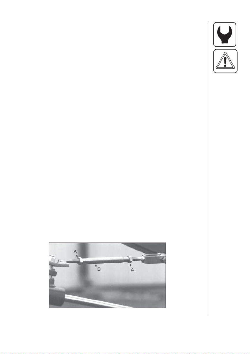
4. Disconnect cylinder rod eye (B) from the intermediate boom section.
5. Loosen jam nut (A) and adjust rod eye (B) IN to move boom forward
or OUT to move boom rearward. Tighten jam nut (A).
6. Reattach cylinder rod to boom and pressurize cylinder to check boom
alignment.
Fig. 37
58
8.4 Aligning Intermediate and Outer Boom Sections
1. Unfold boom into operating (spraying) position.
2. Hold M12x100 adjusting bolt, loosen lock nut, and turn nut so cap
screw head contacts top stop with outer and intermediate boom sections
aligned.
3. Check to ensure that lock nut is tight.
HARDI MEGA 230 / 350 CENTRIFUGAL OPERATORS MANUAL
Page 61
8.5 Adjusting Front Fold Cables
(Fig. 38)
CAUTION: REAR CABLE CAN SNAP AND INJURE YOU OR SOMEONE ELSE IF TENSIONED WHEN THE BOOM IS UNFOLDED.
ALWAYS ADJUST FRONT CABLE FIRST WITH THE BOOM UNFOLDED AND REAR CABLE LAST WITH THE BOOM FOLDED IN
TRANSPORT POSITION.
1. Unfold boom into operating (spraying) position.
2. Shut the tractor off.
3. Slide a straight edge down the underside of intermediate boom
section until it just contacts the front cable.
4. Suspend a 10lb (4.5kg) weight from the straight edge-to-cable contact
point and check deflection by measuring the distance from the straight
edge to the cable. Cable should deflect .50-.75in.(13-20 mm).
5. Loosen jam nuts (A) on the turnbuckle assembly and adjust turnbuckle
(B) for proper cable deflection. (Fig. 38).
6. Tighten jam nuts (A) and remove weight.
IMPORTANT: Check boom alignment again. If front cable was
tightened, the wing assembly will move forward; or
if loosened, wing will move rearward. Adjust fold
cylinder (if necessary) as described in Aligning
Wing Assemblies.
Fig. 38
HARDI MEGA 230 / 350 CENTRIFUGAL OPERATORS MANUAL
59
Page 62
8.6 Adjusting Breakaway Clutch Tension
(Fig. 39)
CAUTION!
Never place fingers into open breakaway clutch or you
may injured should clutch snap closed.
NOTE: Spring pressure from tensioned breakaway clutch assists in
returning outer boom section to alignment.
1. Loosen jam nut C.
2. Tighten nut D to stiffen clutch action. Clutch is properly tensioned
when breakaway boom section returns to alignment with outer boom
section after breaking away. Tighten jam nuts after adjustment.
IMPORTANT: Properly lubricate clutch assembly before adjusting
the tension.
Breakaway clutch cap screws (A) must be torqued to
55 N-m (40lb-ft) every week (40 hours) to prevent
boom damage. Lubricate every day (8 hours) to
ensure maximum performance and life.
A. RETORQUE FASTENE RS
40 Hrs
40 ft/lbs
55 N•m
B. GREASE
A
C
D
60
8 Hrs
B
105192
Fig. 39
HARDI MEGA 230 / 350 CENTRIFUGAL OPERATORS MANUAL
Page 63

8.7 Adjusting Boom Wing To Be Level To Ground
HY-BOOMS
Fig. 40
1. Loosen jam nut A
2. Adjust nut B in or out until wing is level to ground.
3. Secure jam nut A
Same procedure applies to both sides.
HARDI MEGA 230 / 350 CENTRIFUGAL OPERATORS MANUAL
61
Page 64

8.7 Adjusting Boom Wing To Be Level To Ground
(cont'd)
HZ-BOOMS
Fig. 41
62
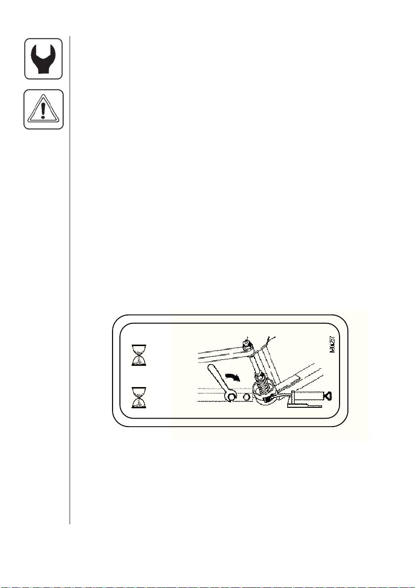
1. Loosen jam nut A.
2. Apply an adjustable wrench to the machined surface at B.
3. Turn the cylinder rod until boom is level to the ground.
4. Secure jam nut A.
Same procedure applies to both sides.
HARDI MEGA 230 / 350 CENTRIFUGAL OPERATORS MANUAL
Page 65
8.8 Adjusting Floating Frame Pivot
NOTE: Lubricate pivot linkage (7 places) and grease skid plates prior
to adjustment.
1. Park machine on level surface.
2. Manually lift one outer boom end approximately 20 in. (490mm)
above horizontal.
3. Release boom end. Boom should smoothly return to horizontal or near
horizontal position.
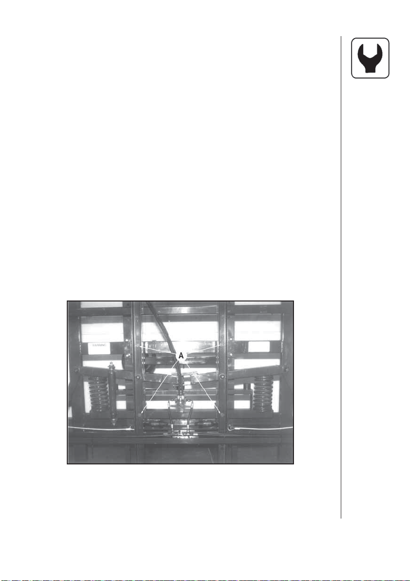
4. If boom does not return to horizontal, loosen each adjustment cap
screw A 1/2 turn and check again. (Fig. 42 )
If boom pivots too freely, tighten adjustment cap screws 1/2 turn and
check again.
Boom is properly adjusted when it returns to horizontal position.
Fig. 42
HARDI MEGA 230 / 350 CENTRIFUGAL OPERATORS MANUAL
63
Page 66

8.9 Adjusting Boom Transport Position
1. Fold boom into transport position. With fold cylinder pressurized,
determine if boom sections need to be adjusted inwards or outwards.
Ensure boom wings will not interfere with tractor wheels or
structure.
2. Relieve pressure from cylinder by unfolding boom a few inches.
3. Loosen jam nut A and adjust collar B IN to move boom out away
from cab or OUT to move boom in toward cab. (See fig. 43)
4. Secure jam nut A.
5. Pressurize cylinder to see if boom is properly adjusted. If not repeat
the above procedure until it is correctly adjusted.
B
A
Fig. 43
8.10 Adjusting Rear Cable
64
CAUTION: REAR CABLE CAN SNAP AND INJURE YOU OR SOME
ONE ELSE IF TENSIONED WHEN THE BOOM IS
UNFOLDED.
ALWAYS ADJUST FRONT CABLE FIRST WITH
THE BOOM UNFOLDED INTO SPRAYING POSITION.
(SECTION 8.5)
1. Raise boom to its highest position. Fold boom to transport position
with tilt cylinders fully extended. Make sure fold cylinders are
pressurized and that boom is folded all the way in.
2. Shut the tractor off.
3. Loosen the jam nuts on the turnbuckle. Adjust (tighten) the turnbuckle
so that the outer wing section contacts the boom transport stop
bracket. Tighten the turnbuckle another three complete turns and
retighten the jam nuts.
HARDI MEGA 230 / 350 CENTRIFUGAL OPERATORS MANUAL
Page 67

9.0 WINTER STORAGE
When the spraying season is over you should devote some extra time to
the sprayer before it is stored.
Hoses
Check that none of the hoses are caught or have sharp bends.
A leaky hose can give an annoying delay in the middle of the spraying
job. Therefore check all the hoses and change if there is any doubt about
the durability.
Paint
Some chemicals are very hard on paints. It is therefore recommended to
remove rust, if any, and then touch up the paint.
Tank
Check that no chemical residues are left from the last spray job. Chemical residues must not be left in the tank for a long time. This will reduce
the life of the tank. See section on cleaning the sprayer.
ESC Controls
When storing the sprayer, the control box and the multiplug must be
protected against moisture and dirt. A plastic bag can be used around the
plug.
P.T.O. shaft
It is important that the push pins are clean and well lubricated, to ensure
safe function.Every 40 hours: Inspection of protection guards, function
and condition. Replace possible damaged parts.Every 1000 hours:
Check condition of protection guards and replace nylon bearings.
Check general condition of cross journals and push-pin/quick release replace if necesary.
Anti-freeze precaution
If the sprayer is not stored in a frost free place you should take the following precautions: Drain as much water as possible from sprayer. Pour in a
mixture of ethylene glycol base anti-freeze and water at the ratio for the
desired temperature protection. (Volume of mixture should be about 1%
of tank volume) Run the sprayer and circulate the anti-freeze in to the
pump, controls and boom lines.
NOTE: NEVER USE OIL OR DIESEL FUEL IN A SPRAYER
The anti-freeze solution also prevents the O-rings and gaskets from
drying out.
Remove the glycerine filled pressure gauge and store it in a frost free and
vertical position.
Remove nozzles & screens. Clean and store in a safe, dry location.
Turn pressure regulator valve counter-clockwise until all spring tension is
released. Turn boom section valves off.
Store sprayer in a safe, dry location away from children and animals.
Protect from direct sunlight.
HARDI MEGA 230 / 350 CENTRIFUGAL OPERATORS MANUAL
65
Page 68

10.0 OPERATIONAL PROBLEMS
In cases where breakdowns have occurred the same factors always
seem to come into play:
Minor leaks on the suction side of the pump will reduce the pump
•
capacity or stop the suction completely.
A clogged suction filter will hinder or prevent suction so that the pump
•
does not operate satisfactorily.
Clogged up pressure filters will result in increasing pressure at the
•
pressure gauge but lower pressure at the nozzles.
Poorly reassembled pumps, and pump fittings, will allow the pump to
•
suck air resulting in reduced or no pumping capacity.
Electrical and hydraulic components that are contaminated will result
•
in poor connections and rapid wear to the hydraulic system.
Therefore ALWAYS check:
1. Suction, pressure and nozzle filters are clean.
2. Hoses for leaks and cracks, paying particular attention to suction
hoses.
3. Gaskets and O-rings are present and in good condition.
4. Pressure gauge is in good working order. Correct dosage depends on
it.
5. Operating unit functions properly. Use clean water to check.
6. Electrical and hydraulic components are maintained clean.
10.1 Nozzle Tubes and Fittings
66
Poor seals are usually caused by;
• Missing O-rings or gaskets
• Damaged or incorrectly seated O-rings
• Dry or deformed O-rings or gaskets
• Foreign materials
In case of leaks; DO NOT overtighten any fittings.(Fig. 44). Disassemble,
check the condition and position of any O-ring or gasket, clean, lubricate
and then reassemble.
For radial connections (Fig. 44) only hand tighten them.
HARDI MEGA 230 / 350 CENTRIFUGAL OPERATORS MANUAL
Page 69

10.1 Nozzle Tubes and Fittings (cont'd)
The O-rings need to be lubricated ALL THE WAY AROUND before fitting
on to the nozzle tube.
Fig. 44
HARDI recommends using a vegetable based oil to prolong the life of the
O-ring.
10.2 Checking the Valve Cone in Distribution Valves
Periodically check the distribution valves for proper
sealing.
Flush the sprayer with clean water and open
master on/off and all distribution valves. (Shut
sprayer off)
Remove clip A (Fig. 46) and remove hose B for
the constant pressure device. When the housing is
drained make sure everything is clear from part B
then start sprayer, there should not be any flow of
liquid through the constant pressure passage. If
there is any leakage, the valve cone E must be
changed. (Shut sprayer off.)
Remove clip C, and pull the EC-motor off the valve
housing. Then remove D screw and replace the
valve cone E. Reassemble in opposite sequence.
HARDI MEGA 230 / 350 CENTRIFUGAL OPERATORS MANUAL
Fig. 45
67
Page 70

10.3 Emergency Operation of ESC Control
In case of power failure it is possible to operate
all functions of the operating unit manually. First
disconnect the multiplug from the control box.
Now manually turn the emergency control
knobs.
The problem may be due to a blown fuse. The
fuses are placed in the control box and are
marked according to functions. Fuses 7 and 8
are spare fuses.
Fuse type T 500 mA HARDI ref. no.
261125
B
10.4 Level indicator
The level indicator should be
checked regularly. When the tank is
empty, the floater should rest on
the stop pin on the rod and the
O-ring at the indicator should be
positioned at the top position line A.
A
Fig. 46
68
If any deviation is found, pull out
the plug B, loosen the screws C
and adjust the length of the cord.
HARDI MEGA 230 / 350 CENTRIFUGAL OPERATORS MANUAL
C
Fig. 47
Page 71

11.0 TROUBLESHOOTING
11.1 General Spray Systems
Problem Cause
1. No liquid getting to the pump.
2. Lack of pressure.
3. Pressure jumping.
A. Bottom of Suction Tube plugged.
B. Valve on Suction Manifold not in
correct position.
C. Suction filter O-ring air leak.
A. Bottom of suction tube plugged.
B. Motor shaft coupling loose or fork
pin missing.
C. Bad seat on spool valve for boom
section control.
D. PTO speed not fast enough.
E. Valve on Suction Manifold not in
correct position.
F. Bad suction valve or suction side
air leak.
G. PTO not engaged.
H. Valves on Pressure Manifold not in
correct position.
I. Agitation nozzles worn or missing.
A. Output from by-pass lines causing
a disturbance around suction
hose.
B. Small tear or pin hole in suction
hose.
C. PTO shaft slipping on pump
shaft.
D. Bad suction valve or suction side
air leak.
E. Valves on Pressure Manifold not
in correct position.
HARDI MEGA 230 / 350 CENTRIFUGAL OPERATORS MANUAL
69
Page 72

11.1 General Spray Systems (cont'd)
Problem Cause
4. Pressure dropping.
5. Liquid leaking from pump.
6. Electric control not
functioning.
7. Less spray out of one boom
section than others.
A. Output from By-pass Lines
causing a disturbance around
suction tube inside tank.
B. Suction filter plugging.
C. Bad seat on spool valve for boom
section control.
D. Suction Manifold valve or
suction side air leak.
E. Nozzles worn.
A. Damaged pump seal.
A. Fuse blown.
B. Motor bad or micro-switch plate
loose.
C. Bad seat on spool valve.
D. Bad switch or plug on control box.
E. Print board at back of control
corroded or damaged.
F. Check polarity (Brown: Positive)
(Blue: Negative)
A. Bad seat on spool valve for Boom
Section Control.
70
8. Poor agitation.
9. Excessive vibrations in hoses.
HARDI MEGA 230 / 350 CENTRIFUGAL OPERATORS MANUAL
A. Agitation valve not open.
B. Agitation nozzle plugged.
C. Agitation nozzle missing.
A. Bottom of suction tube plugged.
B. PTO shaft slipping on pump crank
shaft.
C. Bad Suction Mainfold valve or
suction side air leak.
D. Valves on Pressure Manifold not
in correct position.
Page 73

General Spray Systems (cont'd)
Problem Cause
10. Can't get tank empty.
11. Boom nozzle leaking.
11.2 Foam Marker
Problem Cause
1. Compressor will not run.
2. Compressor runs but will
not make foam.
3. Will not make enough foam.
A. Output from by-pass lines causing
a disturbance around suction tube.
B. Crack or pin hole in suction tube.
C. Tank is not level.
A. Seat on master shut-off valve worn
or cracked.
B. Bad seat on spool valve.
A. Short in electrical system or bad
compressor.
B. 12 volt supply not connected.
C. Bad printboard.
D. Defective switch in control box.
A. Bad Printboard
B. Not enough Foam Concentrate
C. Solenoid valve plugged.
D. Solenoid not working
A. Line leak or line pinched
B. Solenoid valve plugged
C. Weak Foam Concentrate mixture.
D. Water too hard (add water
softener).
4. Foam drops will not last.
5. Keeps blowing fuses.
HARDI MEGA 230 / 350 CENTRIFUGAL OPERATORS MANUAL
A. Not enough foam concentrate.
B. Frequency valve not opened
enough.
C. Weak Foam Concentrate.
D. Water too hard (Add water
softener)
A. Short in electrical system or bad
compressor.
B. Bad relay on printboard.
C. Tank filter plugged.
71
Page 74

11.3 Flush & Rinse™
Problem Cause
1. System will not flush (pump,
control, and boom)
2. System will flush but not rinse
3. Rinse nozzle has poor
output.
11.4 Chemical Filler
Problem Cause
1. Filler tank will not empty.
2. Filler tank empties too slow.
A. Suction Manifold valve not in
correct position.
B. PTO not engaged.
A. Pressure Manifold valve not in
correct position. Arrow on handle
should point towards rinse nozzle
symbol.
A. Bad Suction Manifold valve or
suction side air leak.
B. Pressure Manifold valve not in
correct position.
C. Chemical filler Pressure Manifold
valve in correct position. (if so
equipped)
A. Pressure Manifold valve not in
correct position.
B. Sprayer pump not running.
A. Bottom tank discharge valve not
open all the way.
B. Restrictor cone from pump supply
not the correct size.
White-9016/9018 Pump
72
3. Filler tank backfills when
bottom tank discharge valve
open.
HARDI MEGA 230 / 350 CENTRIFUGAL OPERATORS MANUAL
A. Restrictor cone from pump supply
line not the correct size (White -
9016/9018 Pump).
B. Restrictor cone missing.
C. Restictor cone on wrong side of
the valve.
Page 75

11.5 Hydraulics
HY/HZ-Model Won't Fold
PROBLEM SOLUTION
Hydraulic lines not hooked- Check the lines for proper
up properly hook-up
Dirt in the restrictors on the Remove restrictors and
cylinders clean them
Restrictor
Fig. 48
HZ-Model Won't Fold
PROBLEM SOLUTION
Hydraulic lines not hooked- Check the lines for proper
up properly hook-up
Switches for hydraulic functions Tun the proper switches on
not turned on
Cable from sprayer not attached Attach cable to control box
to control box
No power supply to control Check all connections and
box cables in power supply
Cable from control box to Replace cable
hydraulic manifold is damaged
HARDI MEGA 230 / 350 CENTRIFUGAL OPERATORS MANUAL
73
Page 76

BOOM WINGS
PROBLEM SOLUTION
Boom won’t fold completely Adjust the fold cylinder
in or out
Boom won’t stay in spray Shut switches off after unfolding
position boom
Boom folds when activating Shut switches not used off
tilt or vice versa. (HZ-models only)
Wing to be kept folded swings Boom must be completely
out, when unfolding other side. unfolded, then fold the desired
wing in
Breakaway won’t hold outer Adjust breakaway, replace
wing stable clutches if worn
Boom won’t go up or down H-frame needs to be greased
Grease on H-frame is dry and
dirty, needing to be replaced
Center is too tight to H-frame.
11.6 HY-Schematic
Readjust center to H-frame
74
L=3100
(10’-2“)
LEFT FOLD
RIGHT FOLD
L=3100
L=3000
L=3000
(9’-10”)
(10’-2”)
(9’-10”)
L=170
(6-11/16 “)
L=170
(6-11/16 “)
L=5000
(16’-5“)
TO TRACTOR
Fig. 49
HARDI MEGA 230 / 350 CENTRIFUGAL OPERATORS MANUAL
Page 77

11.7 HZ-Schematic
TO TRACTOR
L= 5000 (16'5")
RIGHT FOLD
L= 3000 (9'10") L= 3000 (9'10") L= 3100 (10'2")
L= 3100 (10'2")
LEFT FOLD
RIGHT TILT
L= 2300 (7'7") L= 2300 (7'7")
L= 2450 (8') L= 2450 (8')
LEFT TILT
Fig. 50
HARDI MEGA 230 / 350 CENTRIFUGAL OPERATORS MANUAL
75
Page 78

12.0 ACCESSORIES
12.1 Chemical Filler
Fig. 51
Chemical Filler Installed
Will inject all types of chemical formulations, liquid, powder or granules,
into the bottom of the tank near the agitation flow. A cleaning ring
ensures that chemical residue is removed from the tank.
12.2 Chemical Filler Rinse Kit
76
Fig. 52
Chemical-Filler Rinse Kit
A container rinse kit for liquid containers or plastic bags is also available
for installation into the chemical filler hopper. Refer to the Chemical Filler
Operators Manual for instructions.
HARDI MEGA 230 / 350 CENTRIFUGAL OPERATORS MANUAL
Page 79

12.3 Flush System
Fig. 53
Flush & Rinse Tank 1 (22 GAL.)
Flush system provides a means to be able to flush the pump, controls,
boom feed lines and complete boom and nozzles with clean water from
an 80 gal. tank. Refer to the Flush & Rinse System™ Operators Manual
for complete operational instructions.
Fig. 54
Flush & Rinse Tank 2 (22 GAL.)
HARDI MEGA 230 / 350 CENTRIFUGAL OPERATORS MANUAL
77
Page 80

12.4 Tank Rinse System
Rinse Valve & Gauge
Fig. 55
78
Fig. 56
Rinse Nozzle on Top of Tank
The Rinse system can be added to the flush system which provides a
means to rinse the main tank using pressurized water to spray the inside
of the tank through specially designed spinning nozzles. See the Flush &
Rinse™ System Operator Manual for complete operational instructions.
HARDI MEGA 230 / 350 CENTRIFUGAL OPERATORS MANUAL
Page 81

12.5 Foam Marker System
Foam Marker Tank & Compressor
Fig. 57
Fig. 58
Foam Marker Drop Assembly
The Foam Marker helps prevent skipping or over lapping during spray
application of solution, both which can be costly. HARDI Foam Marker
features a sprayer mounted compressor, poly tank, extruded foamer
hoses and in-cab electrical controls providing right or left drop selection
and the rate of foam droplets.
HARDI MEGA 230 / 350 CENTRIFUGAL OPERATORS MANUAL
79
Page 82

12.6 Nurse Tank Quick Fill
Fig. 59
Nurse Tank Quick Fill
A quick attach hook-up for filling the sprayer tank from a nurse tank.
Liquid is fed into the top of the tank through a one-way valve providing a
better mix of water and chemical . The quick fill is equipped with a handy
1/4 turn shut-off valve.
12.7 Front Tank
80
Fig. 60
Front Tank
A front tank is available in either 250 or 350 gallon sizes with a full range
of options and accessories.
HARDI MEGA 230 / 350 CENTRIFUGAL OPERATORS MANUAL
Page 83
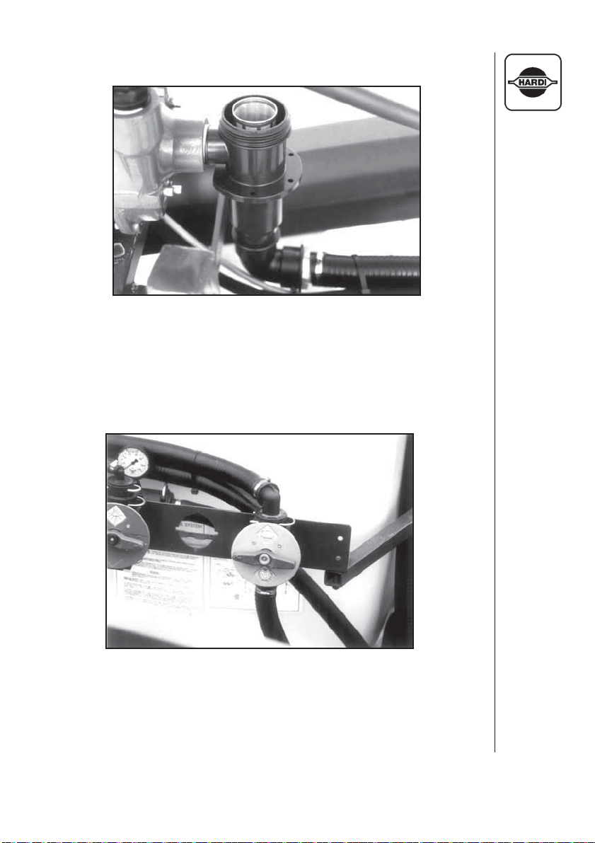
12.8 Suction Filter
Fig. 61
Suction Filter
The suction filter screens out impurities from the spray solution. It is
easily maintained and a variety of screens are available.
12.9 Agitation Shut-Off Valve
Fig. 62
Agitation Bypass Valve
This valve directs either return liquid from the E.C. control to the tank or
back to the pump allowing for more complete draining of the tank before
cleaning.
HARDI MEGA 230 / 350 CENTRIFUGAL OPERATORS MANUAL
81
Page 84

13.0 WARRANTY POLICY AND CONDITIONS
HARDI INC. , 1500 West 76th Street, Davenport, Iowa USA and 290 Sovereign Road, London, Ontario, Canada
hereinafter called "HARDI", offers the following limited warranty in accordance with the provisions below to each
original retail purchaser of HARDI new equipment of its own manufacturer, from an authorized HARDI dealer,
that such equipment is at the time of delivery to such purchaser, free from defects in material and workmanship
and that such equipment will be warranted for a period of one year from the date of delivery to the end user
providing the machine is used and serviced in accordance with the recommendations in the Operators Manual
and is operated under normal farm conditions.
1. This limited warranty is subject to the following exceptions:
a) Parts of the machine are not manufactured by HARDI, (i.e. engines,
b) This warranty will be withdrawn if any equipment has been used for
2. We cannot be held responsible for loss of livestock, loss of crops, loss because of
3. The customer will be responsible for and bear the costs of:
4. Parts defined as normal wearing items, (i.e. tires and V-belts) are not in any way covered
5. This warranty will not apply to any product which is altered or modified without the express
6. Warranty is dependent upon the strict observance by the purchaser of the following
delays in harvesting or any expense or loss incurred for labor, supplies, substitute
machinery, rental for any other reason, or for injuries either to the owner or to a
third party, nor can we be called upon to be responsible for labor charges, other
than originally agreed, incurred in the removal or replacement of components.
a) Normal maintenance such as greasing, maintenance of oil levels, minor
b) Transportation of any HARDI product to and from where the warranty
c) Dealer travel time to and from the machine or to deliver and return the machine
d) Dealer traveling costs.
under this warranty.
written permission of HARDI and/or repaired by anyone other than an Authorized Service
Dealer.
provisions:
a) That this warranty may not be assigned or transferred to anyone.
b) That the Warranty Registration Certificate has been correctly completed by dealer
tires, tubes, electronic controls, and other components or trade accesories, etc.) are not covered by this warranty but are subject to the
warranty of the original manufacturer. Any claim falling into this category will be taken up with the manufacturer concerned.
purposes other than for which it was intended or if it has been misused,
neglected, or damaged by accident, let out on hire or furnished by a
rental agency. Nor can claims be accepted if parts other than those
manufactured by HARDI have been incorporated in any of our equipment. Further, HARDI shall not be responsible for damage in transit
or handling by any common carrier and under no circumstances within
or without the warranty period will HARDI be liable for damages of loss
of use, or damages resulting from delay or any consequential damage.
adjustments, etc.
work is performed.
from the service workshop for repair.
and purchaser with their names and addresses, dated, signed and returned to
the appropriate address as given on the Warranty Registration Certificate.
82
HARDI MEGA 230 / 350 CENTRIFUGAL OPERATORS MANUAL
Page 85

13.0 Warranty Policy and Conditions (continued)
c) That all safety instructions in the operators manual shall be followed and all safety
7. No warranty is given on second-hand products and none is to be implied.
8. Subject to the following terms, conditions and contributions, HARDI extends the warranty on
9. Subject to the following terms, conditions, contributions, HARDI extends the warranty on
10. HARDI reserves the right to incorporate any change in design in its products without
11. The judgement of HARDI in all cases of claims under this warranty shall be final and
12. No employee or representative is authorized to change this warranty in any way or grant any
13. Any warranty work performed which will exceed $400.00
14. Any pump replacement must be approved in advance by the Service Manager.
15. Claims under this policy must be filled with HARDI within thirty (30) days of work performed or
16. Parts requested must be returned prepaid within thirty (30) days for warranty settlement.
17. Warranty claims must be COMPLETELY filled out properly or will be returned.
DISCLAIMER OF FURTHER WARRANTY
THERE ARE NO WARRANTIES, EXPRESSED OR IMPLIED, EXCEPT AS SET FORTH ABOVE. THERE IS NO
WARRANTY OR MERCHANTABILITY. THERE ARE NO WARRANTIES WHICH EXTEND BEYOND THE
DESCRIPTION OF THE PRODUCT CONTAINED HEREIN. IN NO EVENT SHALL THE COMPANY BE LIABLE
FOR INDIRECT, SPECIAL OR CONSEQUENTIAL DAMAGES (SUCH AS LOSS OF ANTICIPATED PROFITS)
IN CONNECTION WITH THE RETAIL PURCHASER'S USE OF THE PRODUCT.
polyethylene tanks (excluding fittings, lids and gaskets) to FIVE YEARS. To qualify for this
extended warranty, the tank must be drained and flushed with fresh water after each day of
use. HARDI's liability is limited to replacement of the tank, FOB our plant at no cost to the
purchaser during the first twelve months; at 20% of the then current price during the second
year ; at 40% during the third year ; at 60% during the fourth year ; and at 80% during the fifth
year. This five year extended warranty is subject, in each instance, to the tank being
inspected and approved for replacement or repair by HARDI personnel before HARDI will
accept any liability hereunder.
HARDI diaphragm pumps (excluding wearing parts such as diaphragms, valves, etc.) to
FIVE YEARS. To qualify for this extended warranty, the pump must be drained and flushed
with fresh water after each day of use. Hardi's liability is limited to replacement of defective
parts, FOB our plant in London, Ontario, Canada at no cost to the purchaser during the first
twelve months after date of purchase, at 20% of the then current retail price during the
second year ; at 40% during the third year ; at 60% during the fourth year ; and at 80% during
the fifth year. This five year extended warranty is subject, in each instance, to the tank being
inspected and approved for replacement or repair by HARDI personnel before HARDI will
accept any liability hereunder.
obligation and to make such changes on units previously manufactured.
conclusive and the purchaser agrees to accept its decisions on all questions as to defect and
to the exchange of any part or parts.
other warranty unless such change is made in writing and signed by an officer of HARDI at its
head office.
by the Service Manager.
warranty shall be void.
guards regularly inspected and replaced where necessary.
MUST be approved IN ADVANCE
HARDI MEGA 230 / 350 CENTRIFUGAL OPERATORS MANUAL
83
Page 86

Notes:
84
HARDI MEGA 230 / 350 CENTRIFUGAL OPERATORS MANUAL
Page 87

WARRANTY REGISTRATION CERTIFICATE
In order to qualify for HARDI warranty, this certificate MUST be completely filled in, signed and mailed to HARDI INC. within 30 days of
delivery of the sprayer.
SPRAYER MODEL:
(Full Description)
SPRAYER ORDER NO. SERIAL NO.
We, the undersigned dealer and purchaser, hereby certify that the above
machine was purchased on the date indicated below.
DEALER NAME
ADDRESS PHONE:
CITY STATE ZIP CODE
PURCHASER NAME
ADDRESS PHONE:
CITY STATE ZIP CODE
NO. OF ACRES FARMED MAJOR CROPS
PURCHASER SIGNATURE
DEALER SIGNATURE
DATE OF PURCHASE
**********************************************************************
FOR OFFICE USE:
REGISTRATION DATE:
CERTIFICATE #
HARDI MEGA 230 / 350 CENTRIFUGAL OPERATORS MANUAL
85
Page 88

86
HARDI MEGA 230 / 350 CENTRIFUGAL OPERATORS MANUAL
Page 89

Page 90

For Product, Service or Warranty Information:
- Please contact your local HARDI® dealer.
To contact HARDI® directly:
- Please use the HARDI® Customer Service number: 1-866-770-7063
- Or send your email to: CUSTSERV@hardi-us.com
HARDI® INC.
HARDI® MIDWEST
1500 West 76th St.
Davenport, Iowa 52806
Phone: (563) 386-1730
Fax: (563) 386-1710
Visit us online at: www.hardi-us.com
®
HARDI
290 Sovereign Rd.
London, Ontario N6M 1B3
Phone: (519) 659-2771
Fax: (519) 659-2821
GREAT LAKES
®
HARDI
5646 W. Barstow, Suite 101
Fresno, California 93722
Phone: (559) 271-3106
Fax: (559) 271-3107
WEST COAST
 Loading...