

Page 1

MASTER
VPZ
Original
Instruction book
67040200-100, version 1.00
GB - 12.2014
www.hardi-international.com
Page 2

We congratulate you for choosing a HARDI plant protection product. The reliability and
efficiency of this product depend upon your care. The first step is to carefully read and pay
attention to this instruction book. It contains essential information for the efficient use and
long life of this quality product.
The original instruction book is approved and published in English. All other languages are translations of the
original. In the event of any conflicts, inaccuracies or deviations between the English original and other languages
the English version shall prevail.
Illustrations, technical information and data in this book are to the best of our belief correct at the time of printing.
As it is HARDI INTERNATIONAL A/S policy permanently to improve our products, we reserve the right to make
changes in design, features, accessories, specifications and maintenance instructions at any time and without
notice.
HARDI INTERNATIONAL A/S is without any obligation in relation to implements purchased before or after such
changes.
HARDI INTERNATIONAL A/S cannot undertake any responsibility for possible omissions or inaccuracies in this
publication, although everything possible has been done to make it complete and correct.
As this instruction book covers more models and features or equipment, which are available in certain countries
only, please pay attention to paragraphs dealing with precisely your model.
Published and printed by HARDI INTERNATIONAL A/S
Page 3

3
1 - EC Declaration
EU Declaration of Conformity
As manufacturer:
HARDI INTERNATIONAL A/S
Herthadalvej 10
4840 Nørre Alslev
DENMARK
hereby declare that the following product
* Further data for this sprayer are shown on its type sign.
fulfils all the relevant provisions of the following Directives of the European Parliament and of the Council:
• 2006/42/EC, regarding the Machinery Directive (CE marking).
• 2009/127/EC and later amendments, regarding machinery for pesticide application.
• 2014/30/EU, regarding electromagnetic compatibility (EMC). Electronic components on the machine are tested and
installed according to the requirements of the EMC Directive.
as well as the following ISO standard:
• ISO 14982, regarding test methods and acceptance criteria for electromagnetic compatibility for agricultural
machinery.
Field sprayer:
Identification number*:
HARDI INTERNATIONAL A/S
Nørre Alslev, Denmark
Date:
Signature:
Name:
Job title:
Page 4

1 - EC Declaration
4
Page 5

Table of Contents
5
Table of Contents
1 - EC Declaration
EU Declaration of Conformity ................................................................................................................3
2 - Safety Notes
Operator Safety .....................................................................................................................................9
Symbols ........................................................................................................................................................................................................................ 9
Precautions ................................................................................................................................................................................................................ 9
Label Explanation ................................................................................................................................................................................................ 11
3 - Description
General info .........................................................................................................................................13
Overview .................................................................................................................................................................................................................. 13
Roadworthiness ................................................................................................................................................................................................... 16
Sprayer Use ............................................................................................................................................................................................................. 16
Frame .......................................................................................................................................................................................................................... 16
Identification Plates ........................................................................................................................................................................................... 16
Tanks ........................................................................................................................................................................................................................... 16
Liquid system ......................................................................................................................................17
Pump .......................................................................................................................................................................................................................... 17
Valves and Symbols ........................................................................................................................................................................................... 17
Control Unit ............................................................................................................................................................................................................ 18
EVC Control Unit .................................................................................................................................................................................................. 18
Clean Water Tank ................................................................................................................................................................................................ 19
Filters ........................................................................................................................................................................................................................... 19
Self-Cleaning Filter ............................................................................................................................................................................................. 19
TurboFiller ................................................................................................................................................................................................................ 20
Diagram - Basic Liquid System ................................................................................................................................................................... 22
Diagram - Liquid System with Options ................................................................................................................................................. 23
BoomPrime ............................................................................................................................................................................................................. 24
Dilution Kit (optional) ....................................................................................................................................................................................... 25
Spray Boom .........................................................................................................................................26
Boom and Terminology .................................................................................................................................................................................. 26
Equipment ...........................................................................................................................................27
Nozzle Pressure Gauge .................................................................................................................................................................................... 27
Footboard ................................................................................................................................................................................................................ 27
Safety Locker .......................................................................................................................................................................................................... 27
Canister for Pesticide Information ............................................................................................................................................................ 28
Tank Level Indicator ........................................................................................................................................................................................... 28
External Cleaning Device (optional) ........................................................................................................................................................ 28
Grip Controls .......................................................................................................................................................................................................... 29
4 - Sprayer Setup
General info .........................................................................................................................................31
Before Putting the Sprayer into Operation ......................................................................................................................................... 31
Unloading the Sprayer from the Truck .................................................................................................................................................. 31
Checking the Suitability of the Tractor ................................................................................................32
General Info ............................................................................................................................................................................................................ 32
Calculating Actual Weights and Loads .................................................................................................................................................. 32
Data Required for the Calculation ............................................................................................................................................................ 33
Calculation of Required Minimum Front Weight ............................................................................................................................ 33
Calculation of Actual Front Axle Load [T3] of the Tractor .......................................................................................................... 34
Calculation of Actual Total Weight [W] of the Combined Tractor and Sprayer(s) ...................................................... 34
Calculation of Actual Rear Axle Load [T2] of the Tractor ............................................................................................................ 34
Calculation Compared to Permissible Values .................................................................................................................................... 34
Transmission shaft ..............................................................................................................................35
Operator Safety .................................................................................................................................................................................................... 35
PTO Installation ..................................................................................................................................................................................................... 35
Mechanical connections ......................................................................................................................36
Quick Hitch .............................................................................................................................................................................................................. 36
Page 6

Table of Contents
6
Hydraulic systems ...............................................................................................................................37
General Info ............................................................................................................................................................................................................ 37
Requirements for Tractor ............................................................................................................................................................................... 37
Closed Centre Hydraulics ............................................................................................................................................................................... 37
Open Centre Hydraulics .................................................................................................................................................................................. 38
Electrical Connections .........................................................................................................................39
Installation of Control Unit Brackets ........................................................................................................................................................ 39
Power Supply ......................................................................................................................................................................................................... 39
Speed Transducer for Tractor ...................................................................................................................................................................... 40
Road Safety Kit ...................................................................................................................................................................................................... 40
Liquid system ......................................................................................................................................41
Self-Cleaning Filter - Choice of Restrictor ............................................................................................................................................ 41
Adjustment of EVC Operating Unit .......................................................................................................................................................... 41
BoomPrime Adjustment ................................................................................................................................................................................. 42
Spray Boom .........................................................................................................................................43
Suspension Effect Adjustment ................................................................................................................................................................... 43
5 - Operation
Spray Boom .........................................................................................................................................45
Safety Info ................................................................................................................................................................................................................ 45
Manoeuvring of the Boom ............................................................................................................................................................................ 46
Manoeuvring of the Boom ............................................................................................................................................................................ 47
Liquid System ......................................................................................................................................48
Filling/Washing Location Requirements .............................................................................................................................................. 48
Filling of Water ...................................................................................................................................................................................................... 48
Filling Through Tank Lid ................................................................................................................................................................................. 49
Filling of Rinsing Tanks .................................................................................................................................................................................... 49
Filling of Clean Water Tank ............................................................................................................................................................................ 49
Safety Precautions - Crop Protection Chemicals ............................................................................................................................. 51
Filling Liquid Chemicals by using HARDI TurboFiller .................................................................................................................... 52
Filling Powder Chemicals by using HARDI TurboFiller ................................................................................................................ 53
TurboFiller Rinsing .............................................................................................................................................................................................. 55
Operating the Control Unit While Spraying - Spray Box III ........................................................................................................ 56
Dilution of Spray Liquid ................................................................................................................................................................................... 57
Before Returning to Refill the Sprayer .................................................................................................................................................... 57
Agitation Before Resuming a Spray Job ............................................................................................................................................... 58
Parking the Sprayer ............................................................................................................................................................................................ 58
BoomPrime ............................................................................................................................................................................................................. 58
Quick Reference - Operation ....................................................................................................................................................................... 59
Cleaning ...............................................................................................................................................60
General Info ............................................................................................................................................................................................................ 60
Quick Reference - Cleaning .......................................................................................................................................................................... 61
Cleaning the Tank and Liquid System ................................................................................................................................................... 62
Cleaning and Maintenance of Filters ...................................................................................................................................................... 62
Use of Rinsing Tank(s) and Rinsing Nozzles ........................................................................................................................................ 63
Use of Detergents ............................................................................................................................................................................................... 64
Technical Residue ............................................................................................................................................................................................... 64
Using the Drain Valve ....................................................................................................................................................................................... 65
Operating Limits .................................................................................................................................................................................................. 66
Liquid Fertilizer ..................................................................................................................................................................................................... 67
Additional Information .................................................................................................................................................................................... 67
6 - Maintenance
Lubrication ..........................................................................................................................................69
General Info ............................................................................................................................................................................................................ 69
Recommended Lubricants ........................................................................................................................................................................... 69
Grease Gun Calibration ................................................................................................................................................................................... 70
Lubrication & Oiling Plan - PTO .................................................................................................................................................................. 70
Boom Lubrication & Oiling Plan ................................................................................................................................................................. 71
Lift Lubrication & Oiling Plan ....................................................................................................................................................................... 71
Page 7

Table of Contents
7
Service and Maintenance Intervals .....................................................................................................72
General Info ............................................................................................................................................................................................................ 72
10 Hours Service - Spraying Circuit .......................................................................................................................................................... 72
10 hours service - Self-Cleaning Filter .................................................................................................................................................... 73
10 Hours Service - InLine Filter (optional) ............................................................................................................................................ 73
50 Hours Service - Transmission Shaft ................................................................................................................................................... 74
250 Hours Service - Hydraulic Circuit ...................................................................................................................................................... 74
250 Hours Service - Hoses and Tubes .................................................................................................................................................... 74
250 Hours Service - Readjustment of the Boom ............................................................................................................................. 74
Occasional Maintenance ......................................................................................................................75
Pump Valves and Diaphragms Renewal ............................................................................................................................................... 75
Pump Valves and Diaphragms Renewal ............................................................................................................................................... 76
Cone Check/Renewal for EVC Distribution Valve ............................................................................................................................ 78
Cone Check/Renewal for Pressure Regulation Valve .................................................................................................................... 78
Level Indicator Adjustment .......................................................................................................................................................................... 79
Level Indicator Cord Renewal ..................................................................................................................................................................... 79
Drain Valve Seal Replacement .................................................................................................................................................................... 79
Adjustment of 3-Way Valve .......................................................................................................................................................................... 80
BoomPrime One-Way Valve ......................................................................................................................................................................... 80
Safety Valve Activation .................................................................................................................................................................................... 80
Feed Pipe Clamp Assembly .......................................................................................................................................................................... 80
Feed Pipe Snap-Lock Assembly ................................................................................................................................................................. 81
Nozzle Tubes and Fittings ............................................................................................................................................................................. 81
Shield Replacement on Transmission Shaft ....................................................................................................................................... 82
Replacement of Transmission Shaft Cross Journals ...................................................................................................................... 82
Change of Light Bulb ........................................................................................................................................................................................ 82
Change of Tyre ..................................................................................................................................................................................................... 82
Readjustment of Boom - General Info ................................................................................................................................................... 83
Boom Lift Adjustment ...................................................................................................................................................................................... 83
Boom Adjustment Order ................................................................................................................................................................................ 84
Trapeze Locking Device .................................................................................................................................................................................. 84
Glide Shoes - Yaw Damping ......................................................................................................................................................................... 84
Horizontal Alignment of Center and Inner Sections ..................................................................................................................... 85
Horizontal Alignment of Inner and Outer Sections ....................................................................................................................... 85
Vertical Alignment of Inner and Outer Sections .............................................................................................................................. 86
Over-Centre Boom Lock Adjustment ..................................................................................................................................................... 87
Off-Season Storage ..............................................................................................................................89
Off-Season Storage Program ....................................................................................................................................................................... 89
After storage ........................................................................................................................................................................................................... 89
7 - Fault Finding
Operational Problems .........................................................................................................................91
General Info ............................................................................................................................................................................................................ 91
Liquid System ........................................................................................................................................................................................................ 92
Hydraulic System, Z-version ......................................................................................................................................................................... 93
Mechanical Problems ...........................................................................................................................94
Emergency Operation - Liquid system .................................................................................................................................................. 94
8 - Technical specifications
Dimensions ..........................................................................................................................................95
General Info ............................................................................................................................................................................................................ 95
Overall Dimensions ............................................................................................................................................................................................ 95
Weight ....................................................................................................................................................................................................................... 96
Specifications ......................................................................................................................................97
Pump Model 363/5.5 ........................................................................................................................................................................................ 97
Pump Model 363/10.0 ..................................................................................................................................................................................... 97
Pump Model 464/5.5 ........................................................................................................................................................................................ 97
Pump Model 464/6.5 ........................................................................................................................................................................................ 97
Pump Model 464/10.0 ..................................................................................................................................................................................... 97
Page 8

Table of Contents
8
Pump Model 464/12.0 ..................................................................................................................................................................................... 97
Filters and Nozzles .............................................................................................................................................................................................. 98
Temperature and Pressure Ranges .......................................................................................................................................................... 98
Power Consumption ......................................................................................................................................................................................... 98
Technical Residue ............................................................................................................................................................................................... 98
Airborne Noise Emission ................................................................................................................................................................................. 98
Tyre Pressure .......................................................................................................................................................................................................... 99
Materials and Recycling .................................................................................................................... 100
Disposal of the Sprayer ..................................................................................................................................................................................100
Electrical Connections ...................................................................................................................... 101
Rear Lights .............................................................................................................................................................................................................101
Electrical Connections for Spraybox II and III ...................................................................................................................................101
EVC Junction Box ...............................................................................................................................................................................................102
Diagrams .......................................................................................................................................... 103
Electrical Specifications for Boom and Work Light ......................................................................................................................103
Boom hydraulics, Z-type ...............................................................................................................................................................................104
Index
Index ................................................................................................................................................. 105
Page 9

9
2 - Safety Notes
Operator Safety
Symbols
These symbols are used throughout the book to designate, where the reader has to pay extra attention. The four symbols
have the following meanings.
€
This symbol means DANGER. Be very alert as your safety is involved!
±
This symbol means WARNING. Be alert as your safety can be involved!
μ
This symbol means ATTENTION. This guides to better, easier and more safe operation of your sprayer!
÷
This symbol means NOTE. Extra information is provided.
Precautions
Please note the following recommended precautions and safe operating practices, before using the sprayer.
General Info
€
DANGER! Read and understand this instruction book before using the equipment. It is equally important, that other
operators of this equipment read and understand this book.
If any portion of this instruction book remains unclear after reading it, contact your HARDI dealer for further
explanation before using the equipment.
€
DANGER! Local law may demand, that the operator is certified to use spray equipment. Adhere to the local law.
€
DANGER! The tractor driver seat is the intended working place during operation.
€
DANGER! When driving on public roads, always ensure that there is no hydraulic pressure to the sprayer.
€
DANGER! Wear protective clothing. Clothing may differ depending on the chemical being sprayed. Adhere to the
local law. Wash and change clothes after spraying. Wash tools if they have become contaminated.
€
DANGER! Do not eat, drink or smoke while spraying or working with contaminated equipment.
In case of poisoning, immediately seek medical advice. Remember to identify the chemicals used.
Filling and Spraying
€
DANGER! No persons are allowed in the operation areas of the sprayer. Be careful not to hit people or surroundings
when manoeuvring the sprayer, especially when reversing.
€
DANGER! Slow down when driving in uneven terrain, as the machine might be in risk of turning over.
€
DANGER! Keep children and animals away from the equipment!
€
DANGER! Do not attempt to enter the tank.
€
DANGER! Do not walk under any part of the sprayer, unless it is secured. The boom is secured when placed in the
transport brackets.
Page 10

2 - Safety Notes
10
Environment
±
WAR NING! I t is e sse nti al to reduce the environmental impact of plant protection chemicals to a minimum. Particularly
the soil, subsoil water, streams, lakes, flora and fauna must be in focus. Contamination of subsoil water must be
prevented by paying particular attention to avoidance of spot contamination of the soil in connection with filling and
washing and parking of the sprayer.
±
WARNING! If any concentrated chemicals are spilled on the soil, the contaminated soil should be removed and sent
for cleaning at a capable facility. This to avoid seepage of chemicals to the subsoil waters. Avoid spillage - use the
chemical filling device for filling the sprayer with chemicals.
μ
ATTENTION! Before filling the sprayer with plant protection chemicals, the sprayer must be calibrated to apply the
precise dose rate selected. The important input sensors are the flowmeter and the speed sensor.
μ
ATTENTION! It is recommended to establish a proper filling and washing location with hard, impenetrable surface
drained to a receptacle if the sprayer is always filled or cleaned on the same spot at the farm. If a washing/filling
location is NOT available, the following precautions should be taken:
μ
ATTENTION! The sprayer should only be filled with clean water at the farm and the plant protection chemicals must
be added and mixed in the field that is going to be sprayed. Select a different location each time the sprayer is refilled.
Service
€
DANGER! Pressure test with clean water prior to filling with chemicals. Never dismount the hoses if the machine is in
operation.
Do not exceed the maximum recommended speed (rpm) for the Power Take-Off (PTO).
€
DANGER! Never service or repair the equipment while it is operating. Always reassemble all safety devices or shields
immediately after servicing.
€
DANGER! Disconnect electrical power before servicing and depressurize equipment after use and before servicing.
€
DANGER If arc welding is used on the equipment, or anything connected to the equipment, disconnect power leads
before welding. Remove all inflammable or explosive material from the area.
€
DANGER! The External Cleaning Device should not be used, if important parts of the equipment have been damaged,
including safety devices, high pressure hoses etc.
±
WARNING! Rinse and wash equipment after use and before servicing.
Page 11
2 - Safety Notes
11
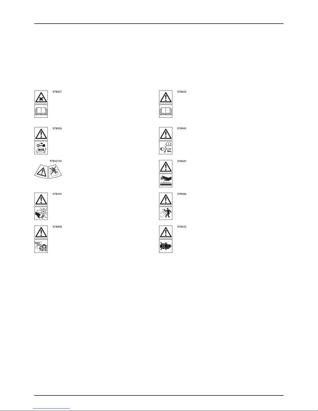
Label Explanation
The labels are designating potential dangerous places on the machine. Anybody working with or being in close range of
the sprayer must respect these labels!
The labels should always be clean and readable! Worn or damaged labels must be replaced with new ones. Contact your
local dealer for new labels.
÷
Note that not all labels shown hereafter will apply to your sprayer.
Chemical handling!
Carefully read the informations about
chemical preparation before handling the
machine. Observe instructions and safety
rules when operating.
Service!
Carefully read operators instruction book
before handling the machine. Observe
instructions and safety rules when operating.
Service!
Shut off the engine and remove ignition key
before performing maintenance or repair.
Service!
Tighten to the torque according to instruction
book.
Risk of death!
Do not attempt to enter tank.
Risk of burn!
Stay clear of hot surfaces.
Risk of injury!
Do not open or remove safety shields while
engine is running.
Risk of injury!
Flying objects - keep a safe distance from the
machine, as long as the engine is running.
Risk of injury!
Keep sufficient distance away from electrical
power lines.
Risk of injury!
Keep hands away.
Page 12
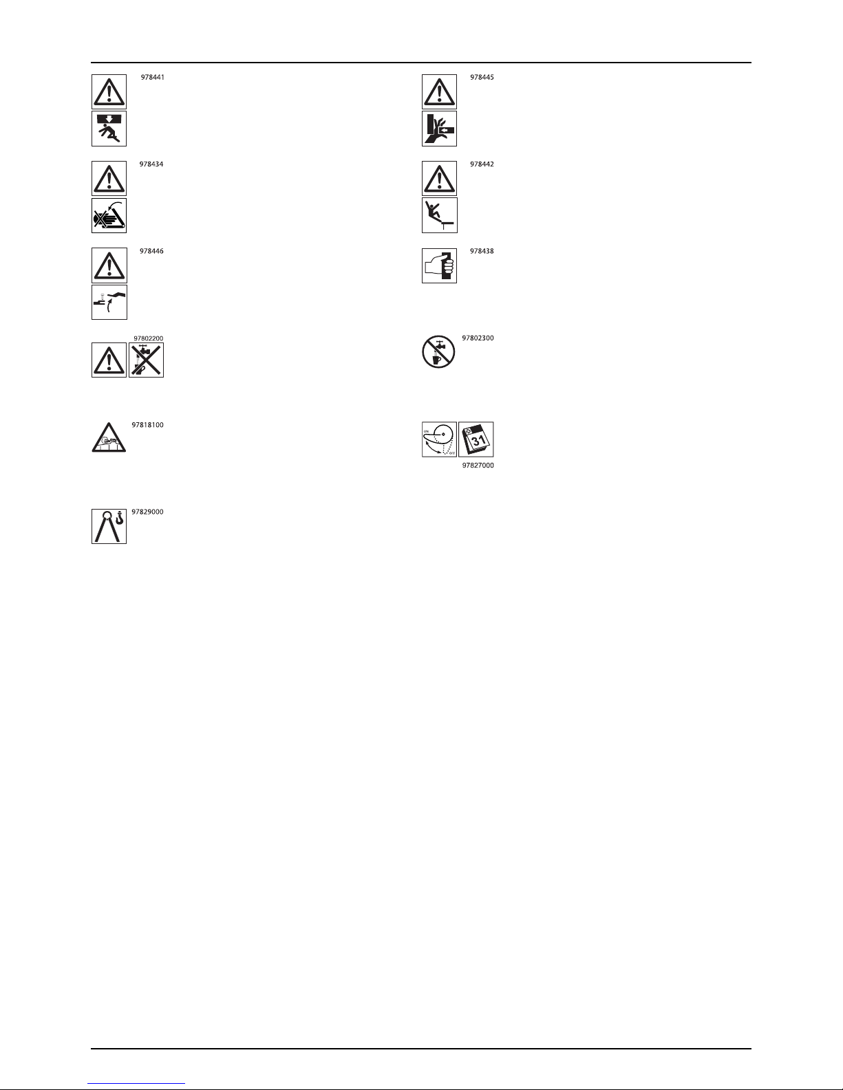
2 - Safety Notes
12
Risk of squeezing!
Stay clear of raised and unsecured loads.
Risk of squeezing
Never reach into the crushing danger area as
long as parts are moving.
Risk of squeezing!
Keep hands away, when parts is moving.
Risk of falling off!
Do not ride on platform or ladder.
Risk of sprayer tipping over!
Be aware when disconnecting the sprayer.
Grapping area!
Manual handling of the boom etc.
Not for drinking!
This water must never be used for drinking.
Not for drinking!
This water must never be used for drinking.
Tank under pressure!
Beware when moving lid.
EasyClean filter service!
Open and clean filter monthly.
Lifting point!
Page 13
13
3 - Description
General info
Overview
An overview of where tanks and equipment are fitted to the sprayer.
Some items are optional - so depending on your purchased sprayer, they might not be included.
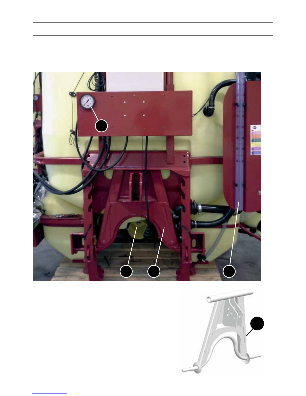
Front view
1. Quick hitch.
2. Power take-off (PTO).
3. Tank level indicator for main tank.
4. Pressure gauge for spray boom (combined with item15).
μ
ATTENTION! Mount the quick hitch on the tractor first
for easy hook-up of the sprayer.
3
2
4
1
1
1
Page 14
3 - Description
14
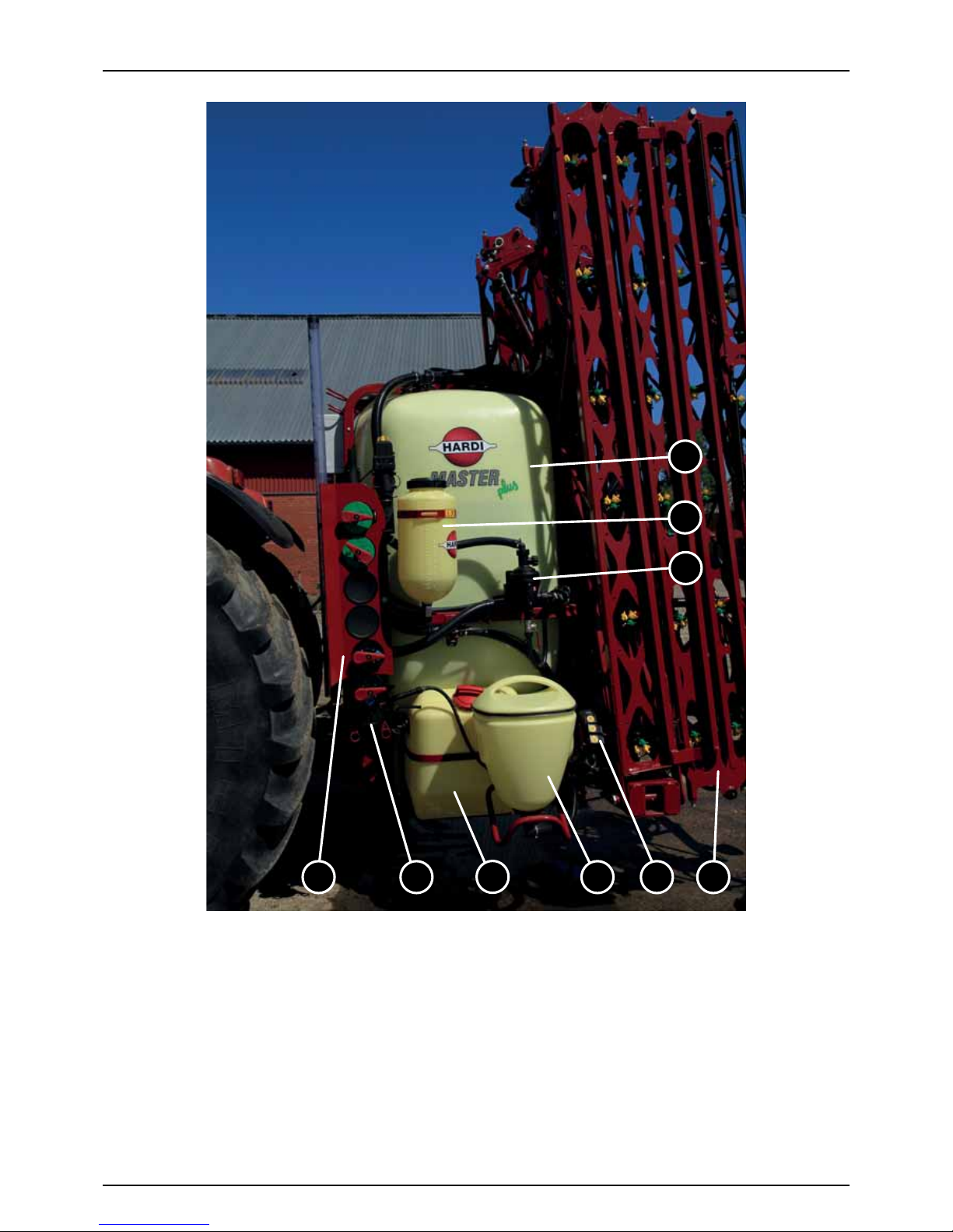
Side view
5. Main tank.
6. Spray boom.
7. Self-cleaning filter.
8. Clean water tank 15 litres.
9. Filling device for main tank.
10. Controls for TurboFiller. Manual valve control.
11. TurboFiller. Device for filling chemicals into the tank.
12. Manifold valve system. Valves to operate the liquid system.
13. Rinsing tank 80 litres. There is one tank on both sides of the sprayer.
11 10
13
12 9
7
8
5
6
Page 15
3 - Description
15
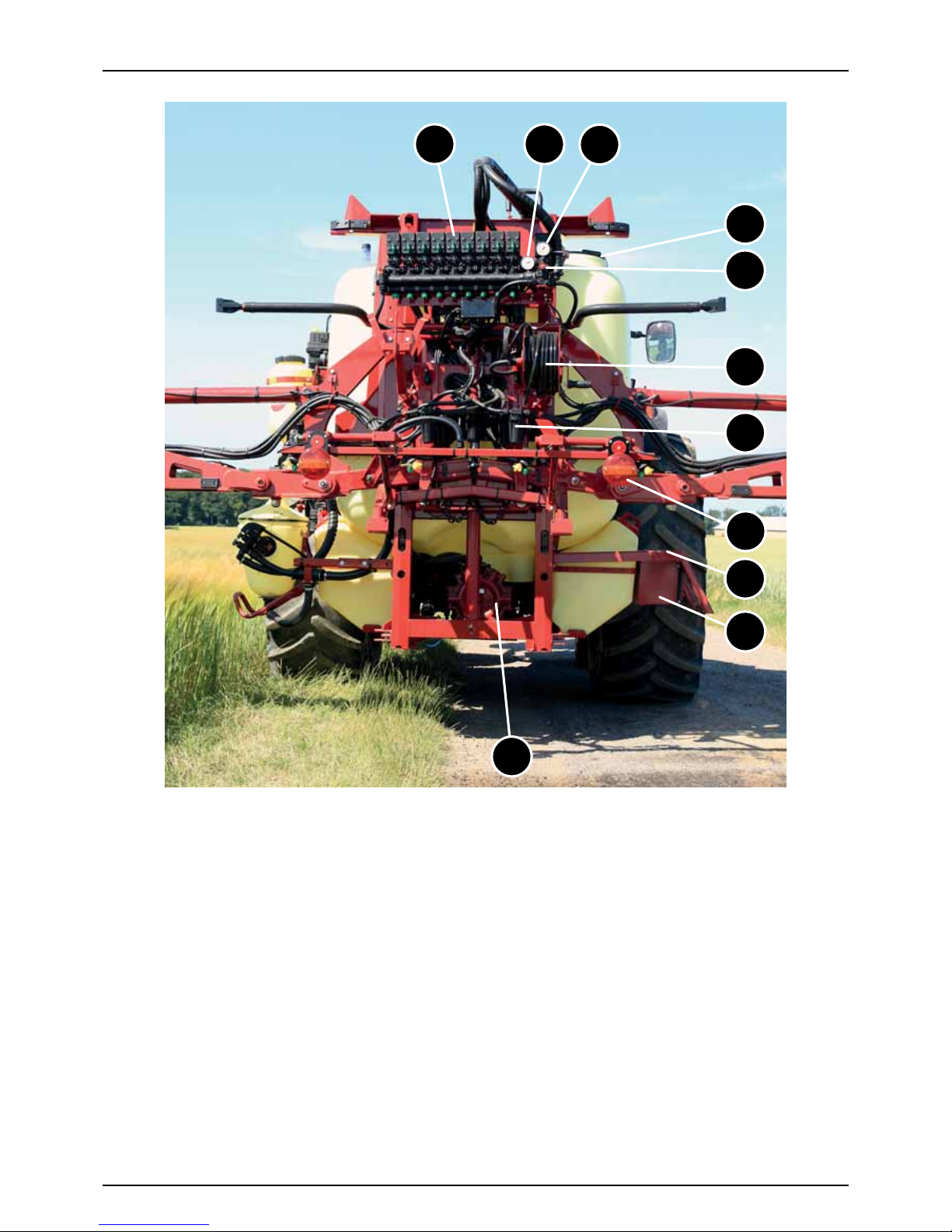
Rear view
14. Pump for liquid system.
15. Hose reel and spray gun for cleaning.
16. Adjuster screw for BoomPrime system.
17. Pressure gauge for BoomPrime system.
18. Operating unit. Electric valve control (EVC).
19. Safety locker. Two-room storage for safety gear.
20. Traffic lights. For connection to tractor’s 7-pin socket.
21. Footboard. Easy access for filling, cleaning of tank, etc.
22. Pressure gauge for spray boom (combined with item 4).
23. InLine filters. Minimize stoppage of spraying due to nozzle blockages.
24. Lid for main tank. The filling hole is placed, so that it can be accessed from the footboard.
20
18
22
24
16
17
15
23
21
19
14
Page 16
3 - Description
16
Roadworthiness
When driving on public roads and in other areas, where the highway code applies, or in areas with special rules and
regulations for marking and lights on implements, you should observe these and equip implements accordingly.
Sprayer Use
The HARDI sprayer is for the application of crop protection chemicals and liquid fertilizers. The equipment must only be used
for this purpose. It is not allowed to use the sprayer for any other purposes. If no local law demands that the operator must
be certified to use spray equipment, it is strongly recommended to be trained in correct plant protection and in safe
handling of plant protection chemicals to prevent unnecessary risk for persons and the environment, when carrying out
your spray job.
Frame
Very strong and compact steel frame with a strong chemically resistant and weatherproof electrostatic lacquer coat. Screws
and bolts etc. have been Delta/Magni treated to be resistant to corrosion.
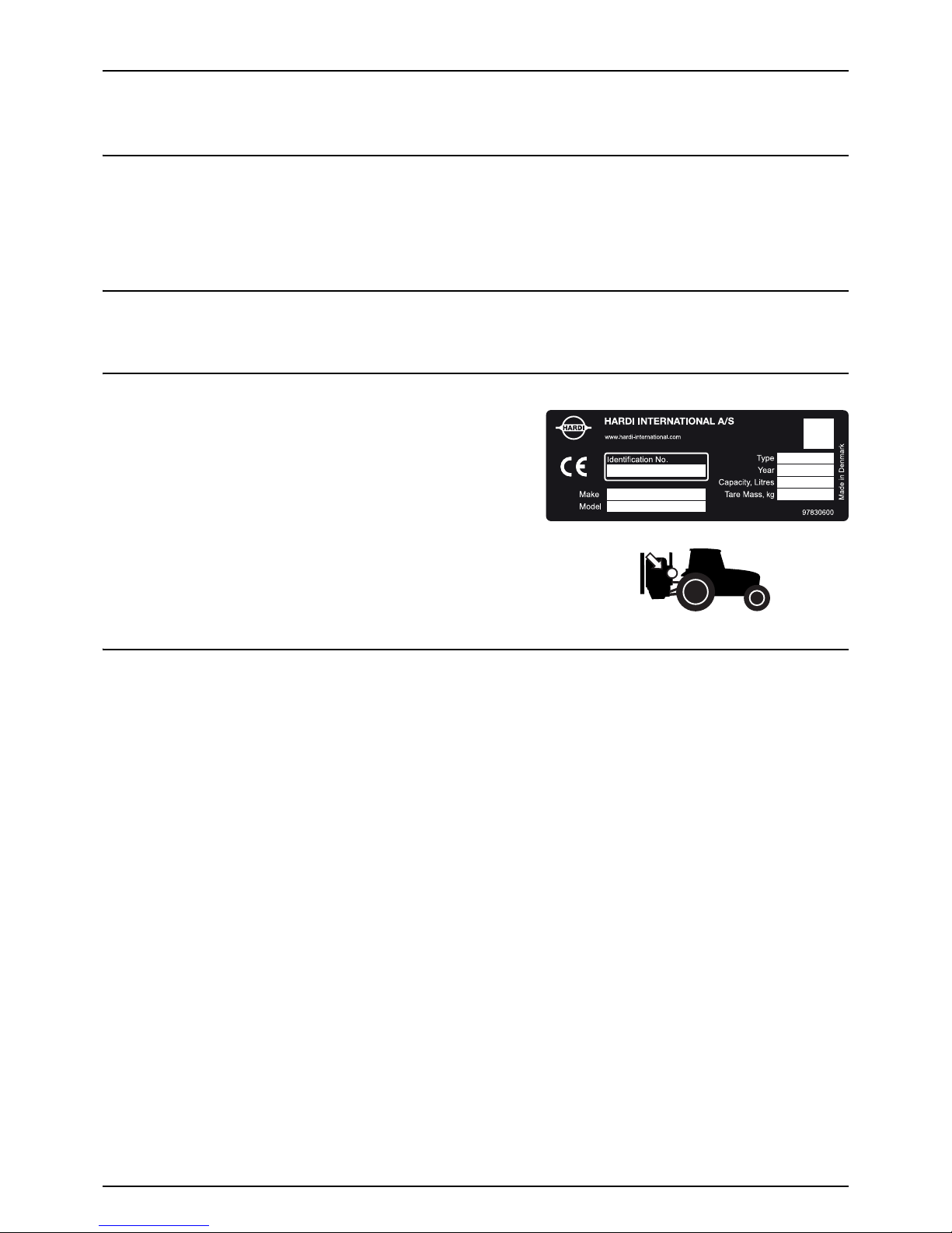
Identification Plates
CE identification plate fitted on the frame indicates producer name,
identification no., make, model, type, production year, tank capacity and
tare mass for the sprayer.
This plate is located on the front side of the sprayer.
Ta nk s
The tanks are made of impact-proof polyethylene, resistant to UV radiation and chemicals. The main tank has a purposeful
design with no sharp corners for easy cleaning. The filling hole is placed so it can be accessed from the platform. This ensures
an easy access for the filling of sprays, cleaning of the tank etc. The sprayer may also be equipped with two rinsing tanks and
a clean water tank.
Nominal tank contents are 1200, 1500 or 1800 litres.
-1-
-2-
-3-
-4-
-5-
-6-
-7-
-8-
Herthadalvej 10 - 4840 Nørre Alslev - Denmark
Page 17
3 - Description
17
Liquid system
Pump
Diaphragm pump with 3 diaphragms, model 1303 or diaphragm pump
with 6 diaphragms, model 363 or 364 or 464.
Standard = 540 rpm (6 splines shaft). The design of the diaphragm pump
is simple, with easily accessible diaphragms and valves, which ensure
that liquid does not contact the vital parts of the pump.
Pump model 363 is shown on the picture.
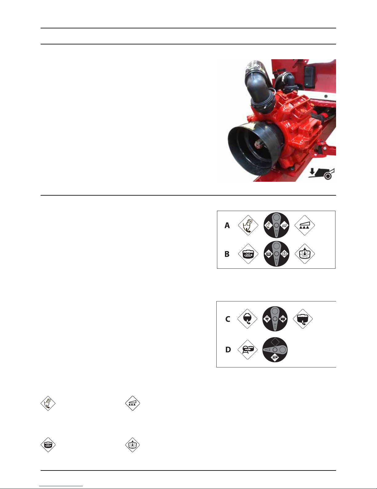
Valves and Symbols
The valves of the valve system are distinguished by coloured
identification on the function labels. Symbols corresponding to every
possible function of use are located on the discs for easy identification
and operation. The modular manifold system facilitates the addition of
optional extras on both pressure side and suction side.
Furthermore the suction manifold can be fitted with a return valve,
which ensures better draining of the sprayer before cleaning.
A function is activated by turning the handle towards the desired
function. If the handle is turned to a label-free position (unused
function), the valve is closed. The valves are:
A. Agitation Valve
B. Pressure Valve
C. Suction Valve
D. External Filling Valve (optional equipment)
A - Pressure valve
With this valve you can select where to direct pressurized liquid.
B - Agitation valve
With this valve you can select between agitation in the tank or tank cleaning using the rinsing nozzle.
Filling of main tank from
TurboFiller
Spraying
Adjustable agitation Tank rinsing nozzle
Page 18
3 - Description
18
C - Suction valve
With this valve you can select suction from main tank (for spraying) or from rinsing tank.
D - External Filling Device valve (optional)
This valve is used, when filling from an external tank or reservoir.
Activating the valve starts/stops the filling process. Note that the suction valve must be closed for maximum filling capacity.
μ
ATTENTION! If a valve is too tight to operate - or to loose (= liquid leakage), the valve needs to be serviced. Please see
the section ‘Maintenance’ for further information.
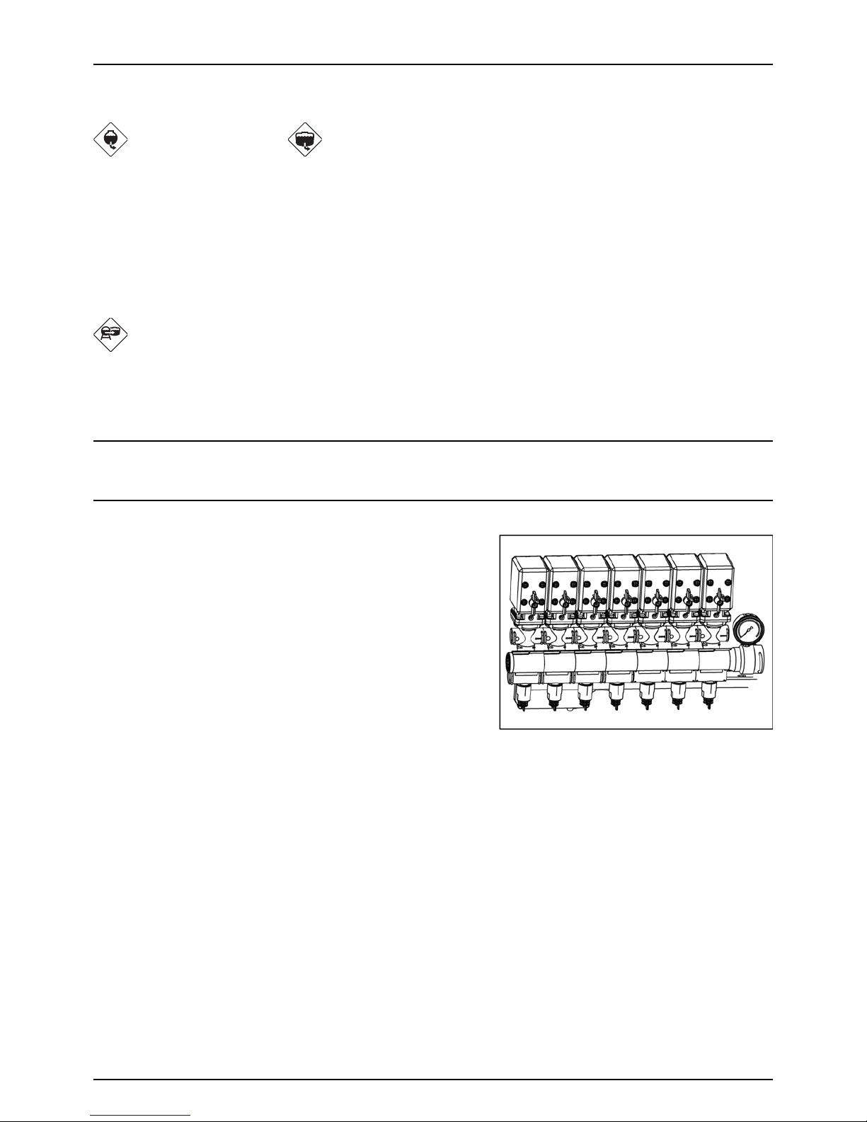
Control Unit
The sprayer is equipped with an EVC control unit.
EVC Control Unit
The system is based on EVC - Electrical Valve Control. The ON/OFF is
linked to the section valves (one valve for each spray boom section),
which results in a quick response to ON/OFF. The operating unit is of
modular design, and it is electrically controlled by a remote control box.
The section valves are fitted with a constant pressure device and a
pressure drop line.
These features allows the operator to shut off individual boom sections.
The unit has a built-in HARDI-MATIC system. This system ensures a
constant liquid volume per hectare (l/ha) when driving forward at
varying speed within the same gear, as long as the number of PTO
revolutions are kept between 300-600 rpm.
Suction from rinsing tank Suction from main tank
Suction from external tank
Page 19
3 - Description
19
Clean Water Tank
The water in this tank is for hand washing, for cleaning of clogged
nozzles etc. Only fill this tank with clean water from the well.
The clean water tank is placed on the sprayer’s left side, right behind the
manifold valves.
Capacity: approximately 15 litres.
±
WARNING! Although the clean water tank is only filled with clean
water, this water must NOT be used for drinking.
Filters
A suction filter is fitted at the top of the tank. It is indicated with a red
hose tail.In-line pressure filters can be fitted at each boom section as an
option(J). However, it is standard equipment on this sprayer.
Nozzle filters are fitted at each nozzle.
All filters should always be in use and their function should be checked
regularly. Pay attention to the correct combination of filter and mesh
size. For more, see “Technical Specifications” in this book.
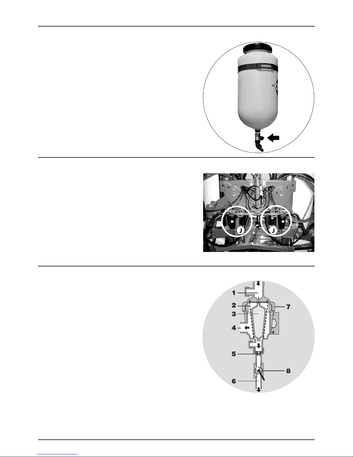
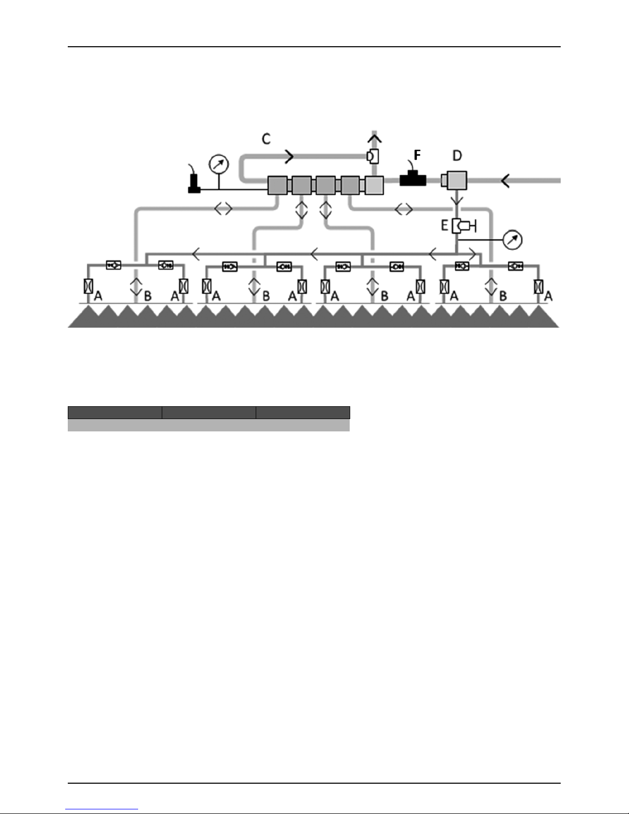
Self-Cleaning Filter
With the self-cleaning filter, the impurities that exist in the spray liquid
will be filtered out and returned to the tank via the return flow.
Function diagram:
1. From pump
2. Double filter screen
3. Guide cone
4. To operating unit
5. Exchangeable restrictor
6. Return to tank
7. Screw joint
8. Ball valve
Ball valve (8) should normally be open, but it may be closed in situations,
where return flow is to be avoided, e.g. flushing of spray lines without
diluting the spray liquid in the main tank.
μ
ATTENTION! If the ball valve is closed, the self-cleaning function is inoperative!
Page 20
3 - Description
20
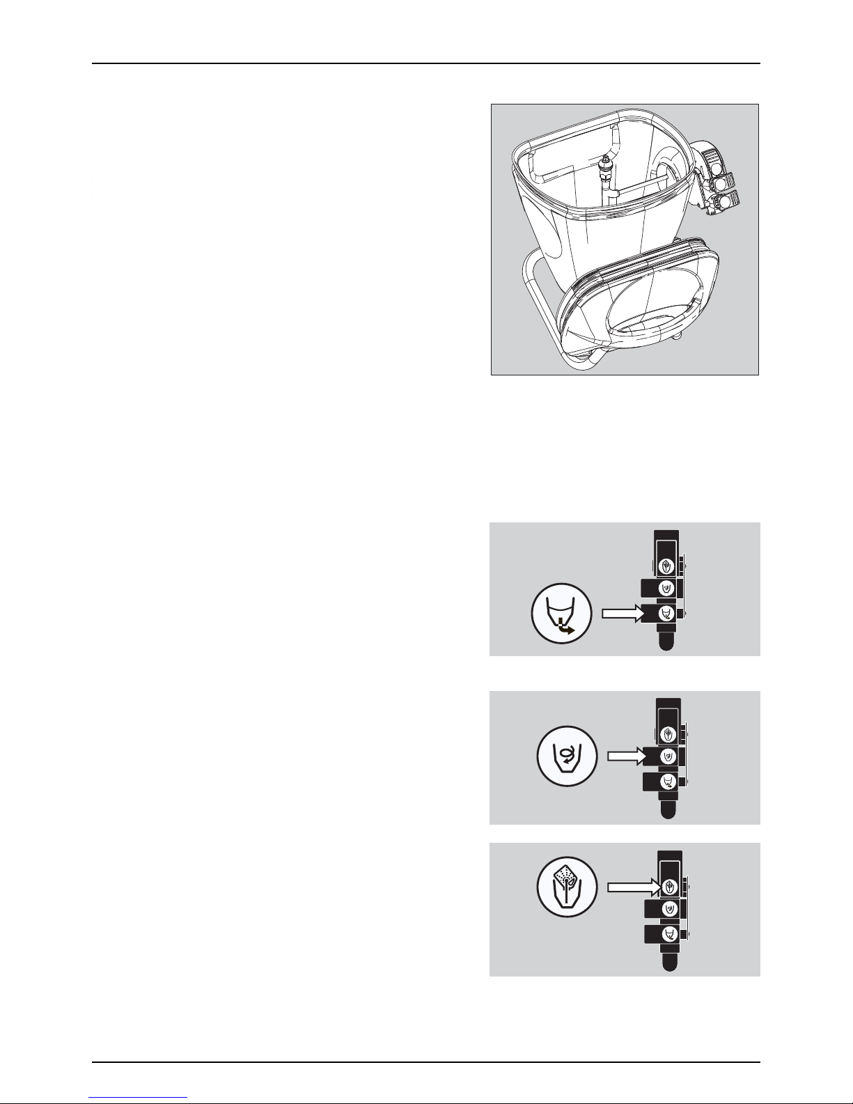
TurboFiller
•
•
TurboFiller Suction Valve
The valve is used simultaneously with the TurboFiller. The valve has 2
settings: Continuously open or spring loaded normally closed. Open the
valve when chemicals are to be filled into the TurboFiller and transferred
to main tank.
TurboDeflector Valve
This TurboDeflector valve activates the vortex flushing of the TurboFiller.
Lift the lever to lock it in open position for continuous liquid rotation in
the hopper.
Chemical Container Rinsing Lever
The upper lever is used for two purposes.
When the TurboFiller lid is open:
For rinsing empty containers. Place the container over the rotating
flushing nozzle in the middle of the TurboFiller to rinse the inside of the
container.
When the TurboFiller lid is closed:
Suction from TurboFiller
Start TurboDeflector
Page 21

3 - Description
21
Use the Chemical Container Rinsing lever to rinse the hopper, when the filling of chemicals is completed.
€
DANGER! Do not press the lever, unless the multi-hole nozzle is covered by a container, as spray liquid may otherwise
hit the operator.
Chemical Container Rinsing
Page 22
3 - Description
22
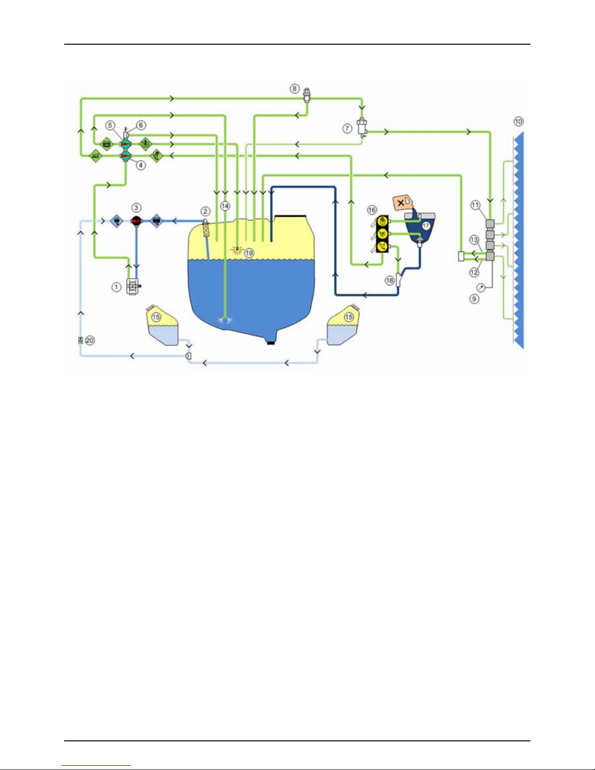
Diagram - Basic Liquid System
1. Pump
2. Suction Filter
3. Suction Valve
4. Pressure Valve
5. Agitation Valve
6. Safety Valve
7. Self-Cleaning Filter
8. Pressure Regulation
9. Pressure Gauge
10. Spray Boom
11. Distribution Valves
12. Return - Pressure Drop
13. Return - Pressure Equalization
14. Agitation Tube
15. RinseTank
16. Valve Block for TurboFiller
17. TurboFiller
18. Ejector for TurboFiller
19. Tank Rinsing Nozzle
20. One-Way Valve
Page 23
3 - Description
23
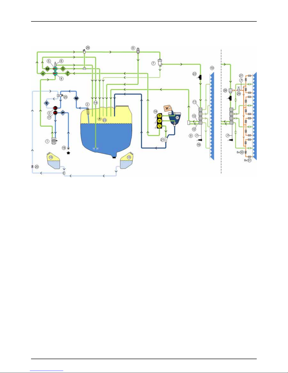
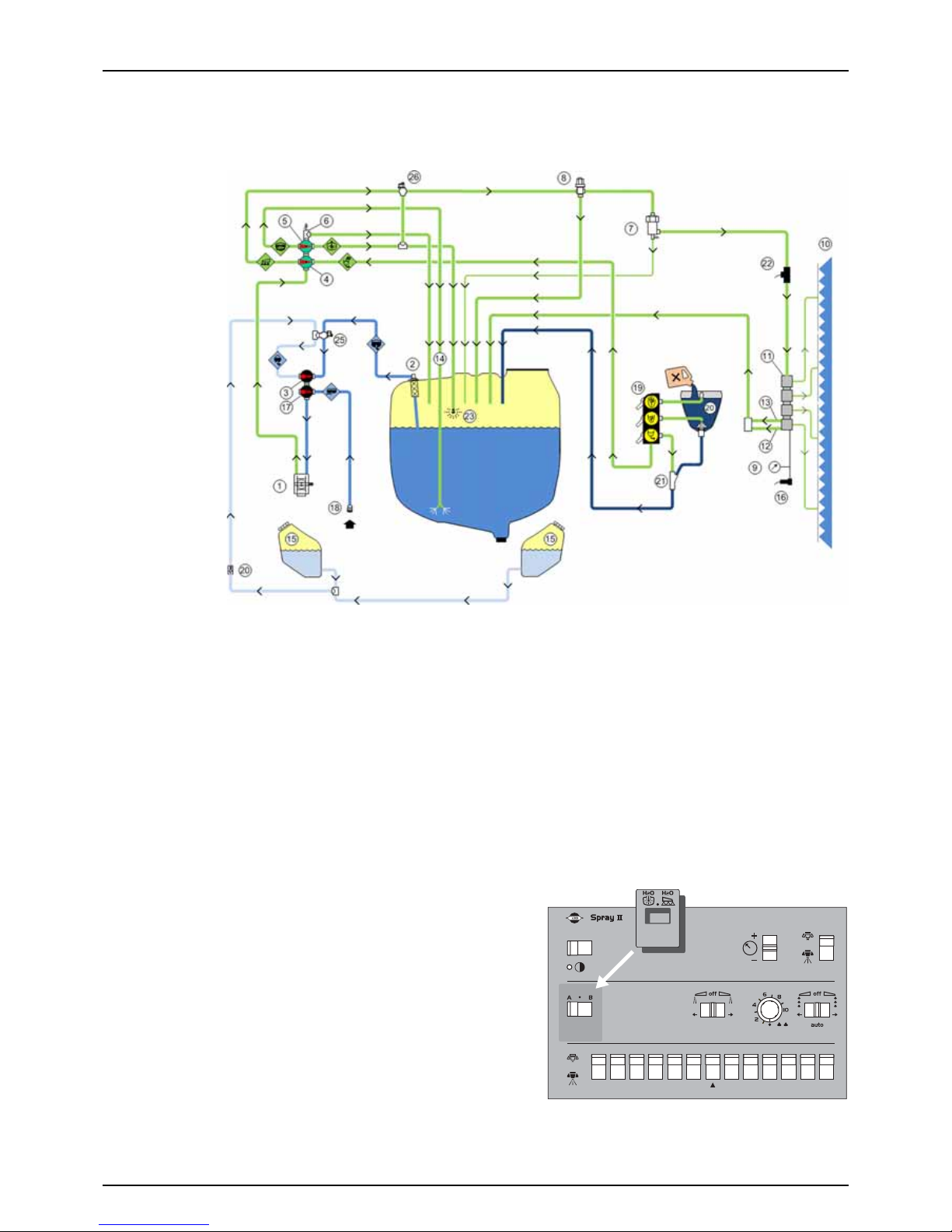
Diagram - Liquid System with Options
BoomPrime system
1. Pump
2. Suction Filter
3. Suction Valve
4. Pressure Valve
5. Agitation Valve
6. Safety Valve
7. Self-Cleaning Filter
8. Pressure Regulation
9. Pressure Gauge
10. Spray Boom
11. Distribution Valves
12. Return - Pressure Drop
13. Return - Pressure Equalization
14. Agitation Tube
15. RinseTank
16. Pressure Sensor
17. Filling Valve
18. Filling Coupler
19. Valve Block for TurboFiller
20. TurboFiller
21. Ejector for TurboFiller
22. Flowmeter
23. Tank Rinsing Nozzle
24. One-Way Valve
25. Dilution Valve for Suction
26. Dilution Valve for Rinsing
27. Pressure Gauge
28. Bypass Valve
29. Pressure Control Valve
30. One-Way Valve
31. Restrictor
Page 24
3 - Description
24
BoomPrime
BoomPrime is a low pressure circulation system, which primes the spray boom tubes prior to spraying, ensuring a
homogenous fluid in the boom tubes and in the main tank. Below the illustration shows the BoomPrime system for the
boom. Components are explained in the diagrams for the liquid systems.
•
The BoomPrime system is attached to each end of a boom section (A).
• The boom spray sections are fed into the middle of each section (B).
Liquid for BoomPrime is taken through a bypass valve (D) just before the flowmeter. This valve operates in opposite phase:
When priming, the direction of liquid flow will be reversed. The liquid will be fed into the nozzle tubes from each end, and
they will then return any water back to the main tank through the EFC section valves return line (C).
The BoomPrime pressure is adjusted by the handle on the control valve (E), which comprises a pressure gauge.
For adjustment, see the section “BoomPrime Adjustment”.
Operating state Section valves Bypass valve
Spraying Open Closed
Not spraying Closed Open
Page 25
3 - Description
25
Dilution Kit (optional)
The dilution kit is a built-in system consisting of the two valves (no. 25 and 26 below) added to the liquid system, enabling
the liquid to be redirected from the rinsing tanks into the main tank and piping to dilute the spray liquid residues.
The dilution kit will ease diluting of chemicals in main tank or boom piping done from the drivers seat, while driving in the
field. This can be useful when interrupting a spray job, e.g. because of rain or before the tank has to be refilled at the farm.
The dilution kit has two functions which are selected from the optional function switch on the Spray Box in the tractor.
• Tank dilution: Dilute boom piping and the main tank at the same time.
• Boom dilution: Dilute the boom piping only.
÷
NOTE! The dilution kit is NOT a rinsing device. For rinsing the sprayer, please see the section “Cleaning” in this book.
÷
NO TE! Dilu tion of che mical resi dues m ay be req uire d by la w in c er tai n situ atio ns bef ore ret urning to th e farm f or f illin g
or cleaning. Please familiarize with applicable rules and follow these.
Dilution kit label
As the Dilution kit uses the optional function switch on the Spray Box, a
label (HARDI item no. 97617800) has to be fitted before use. The label is
to easily recognize, which function of the Dilution kit is to be selected.
Place the label around the switch used for optional functions, as shown
on the picture.
Page 26
3 - Description
26
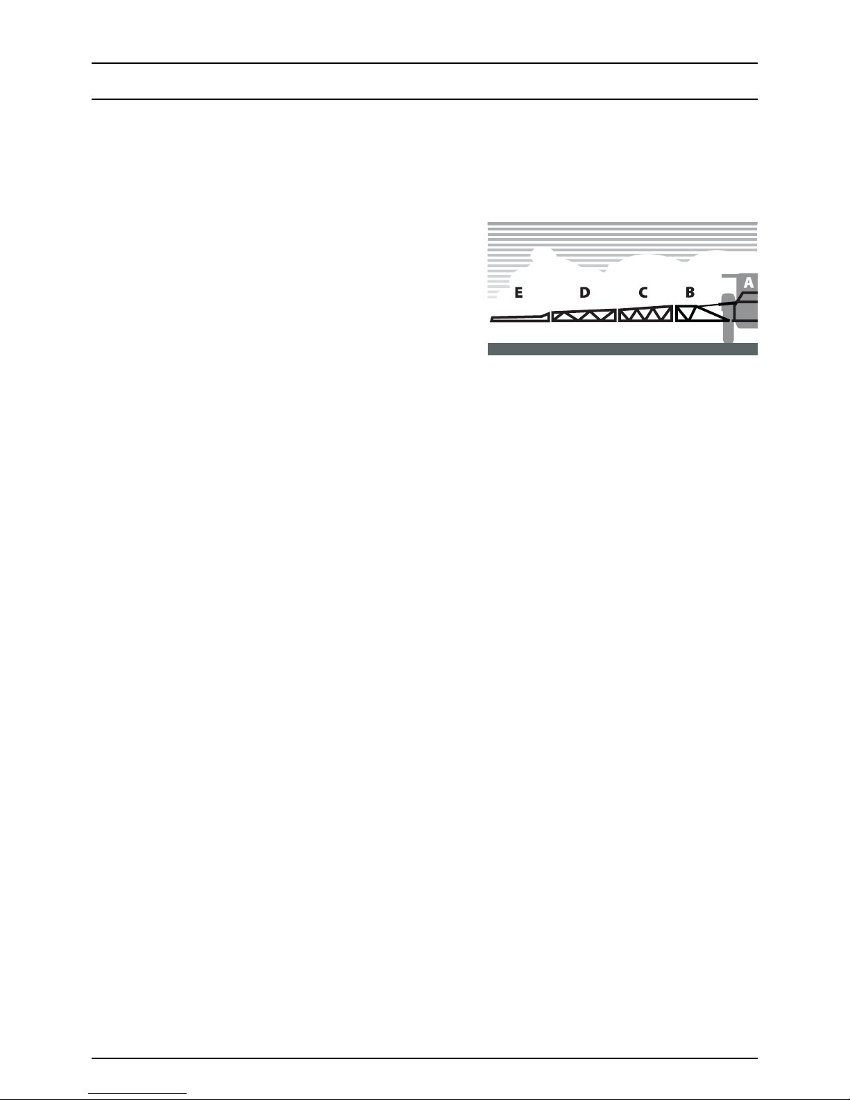
Spray Boom
Boom and Terminology
The sprayer is fitted with a VPZ boom. The boom is supported by a trapeze fitted to the tank frame.
The trapeze helps the boom to stay horizontal when unfolded, and it protects the boom against vibrations and shocks, when
driving on uneven ground. This ensures longer boom life and improves boom stability for better spray distribution.
Booms are available in 20, 21, 24, 27 and 28 m working width. All booms are provided with spring loaded breakaway.
For 3-folded booms, the terminology is as follows:
A - Centre section
C - Middle section
D - Outer section
E - Breakaway section
Page 27
3 - Description
27
Equipment
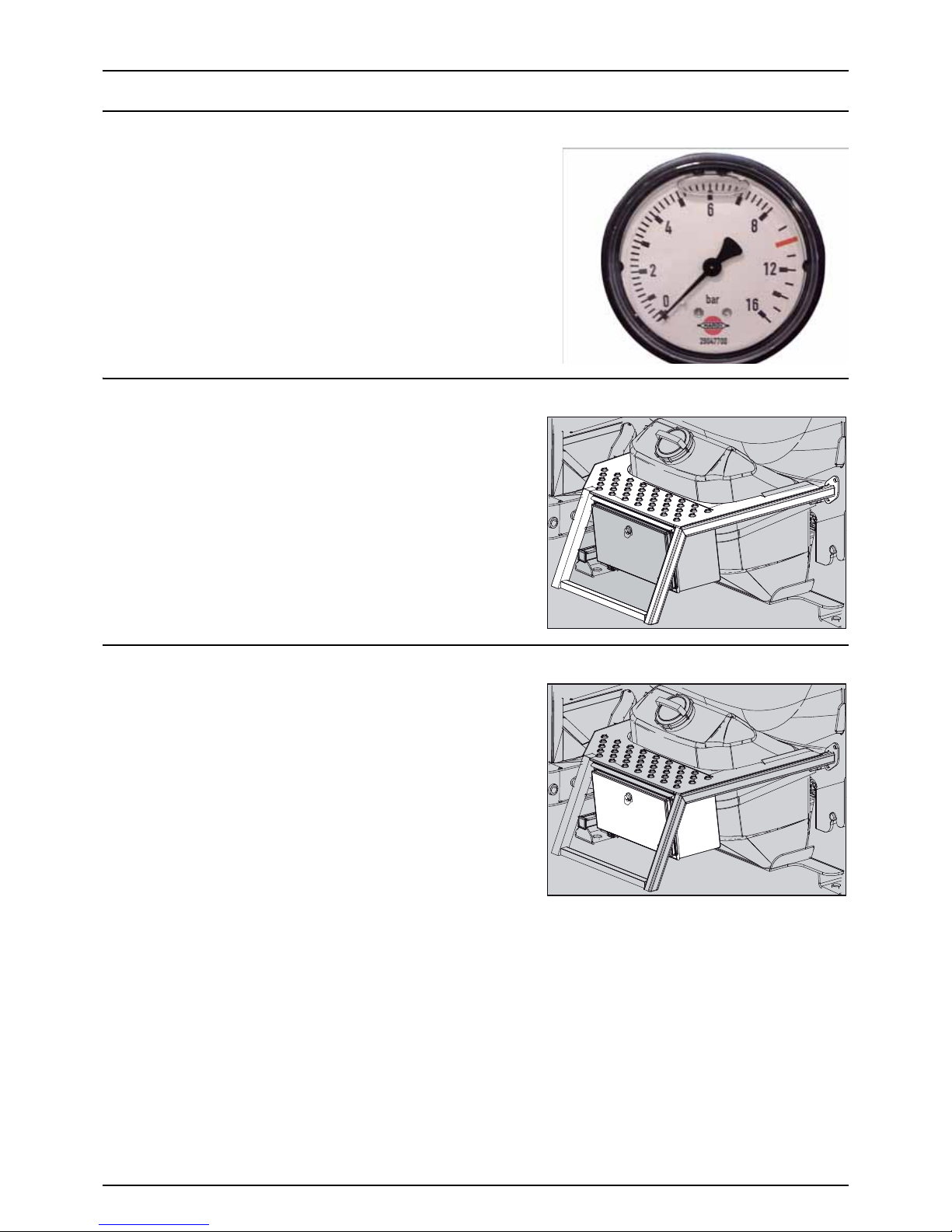
Nozzle Pressure Gauge
The remote pressure gauge is integrated at the front of the sprayer. This
gauge measures the working pressure in the boom tubes as close to the
nozzles as possible.
The outputs stated in the nozzle charts are always based on the pressure
measured at the nozzle. Both when calibrating and spraying, the
pressure must be adjusted according to the readings of this pressure
gauge.
Footboard
The footboard gives access to the main tank lid. It ensures easy access
for filling of sprays, cleaning of tank, etc.
Safety Locker
The safety locker is for storage of safety gear such as non-contaminated
protective gear, soap for hand washing etc. The locker is split in two
compartments for the separation of clean clothes and contaminated
equipment.
±
WARNING! Although this locker is meant for the storing of noncontaminated items, it must never be used for the storing of food,
beverage or other items meant for human consumption.
Page 28
3 - Description
28
Canister for Pesticide Information
This canister is for storing information about the present pesticide
product in the tank - such as labels, instructions and safety data sheet
(SDS) from the pesticide supplier.
The canister is placed on the side of the footboard.
Unscrew the lid and store this information inside the canister at all times
when using the sprayer.
μ
ATTENTION! Although this canister is meant for the storing of
non-contaminated items, it must never be used for the storing of
food, beverage or other items meant for human consumption.
Tank Level Indicator
The actual tank level in the main tank can be observed on the tank level
indicator. The scale is displayed in litres (or Imp. gal/US gal. for certain
countries).
External Cleaning Device (optional)
This equipment comprises a hose reel for cleaning the complete sprayer
externally in the field with clean water. The External Cleaning Device is
located on the boom centre section at the back.
±
WARNING! The cleaning device produces a high water pressure.
Incorrect use may result in injuries!
€
DANGER! Never work in bare feet or sandals. It is recommended
to wear goggles during the cleaning work. It is recommended
that the user, or anyone near the cleaning place, protects himself
against particles bouncing up during the cleaning.
€
DANGER! For the safety of yourself and others, the following rules should always be observed:
Never point the water jet at people, animals, electrical installations or other sensitive objects.
Never try to clean clothing or footwear which you or other people are wearing.
Page 29
3 - Description
29
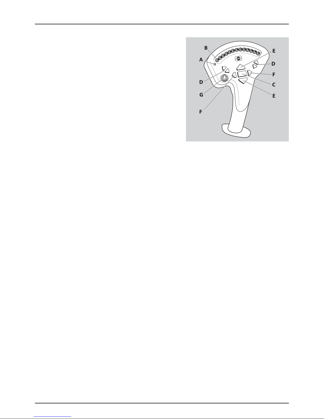
Grip Controls
The grip controls the following:
A. Status light (LED)
B. Boom section controls
C. Main ON/OFF for spraying
D. Boom tilt
E. Boom height
F. Boom slant
G. Option selection switch
÷
Grip controls are not available for HARDI Controller 5500 (HC
5500).
Page 30

3 - Description
30
Page 31

31
4 - Sprayer Setup
General info
Before Putting the Sprayer into Operation
Although the sprayer has been supplied with a strong and protective surface treatment on steel parts, bolts etc. in the
factory, it is recommended to apply a film of anti-corrosion oil (e.g. CASTROL RUSTILO or SHELL ENSIS FLUID) on all metal
parts in order to avoid chemicals and fertilizers discolouring the enamel.
If this is done before the sprayer is put into operation for the first time, it will always be easy to clean the sprayer and keep
the enamel clean for many years. This treatment should be carried out every time the protection film is washed off.
Unloading the Sprayer from the Truck
For the unloading of the sprayer, you need a crane. When unloading
with a crane, please observe the lifting points as shown in the picture,
and make sure that the straps or belts used for lifting are strong enough.
μ
ATTENTION! Only lift the sprayer when the tanks are empty!
Page 32

4 - Sprayer Setup
32
Checking the Suitability of the Tractor
General Info
Before connecting the sprayer to your tractor, you must check the suitability of the tractor. Only connect a tractor which is
suitable for the purpose.
Perform a brake test to check whether the tractor achieves the required braking rate with the sprayer connected.
€
DANGER! An unsuitable tractor, or improper use of the tractor, causes a risk of:
• insufficient tractor stability, steering and braking power
• severe or fatal injuries
• the sprayer being damaged during operation
Requirements for the suitability of a tractor are, in particular:
• Permissible total weight
• Permissible approved axle loads
• Load capacity of the tyres fitted
• Approved front weights must be sufficient
You can find this data on the rating plate of the tractor or in the tractor’s instruction manual or documentation. Ask your
tractor dealer if in doubt.
The front axle of the tractor must always be subjected to at least 20% of the total weight of the vehicle.
The tractor must achieve the braking rate specified by the tractor manufacturer, even with the sprayer connected.
Calculating Actual Weights and Loads
The permissible total tractor weight, specified in the tractor documentation, must be greater than the sum of the:
• Tractor’s tare weight
• Tractor’s ballast and weights
• Sprayer’s total weight
Page 33

4 - Sprayer Setup
33
Data Required for the Calculation
Calculation of Required Minimum Front Weight
To ensure the tractor’s steering capability, the minimum front weight [W2
min
] is calculated:
T1 (kg) Tractor empty weight.
See tractor’s instruction book or documentation.T2 (kg) Rear axle load of the empty tractor.
T3 (kg) Front axle load of the empty tractor.
W1 (kg) Total weight of rear-mounted sprayer with a full tank. See the section “Technical Specifications” in this
instruction book and add the weight of your spray liquid
for a full tank.
W2 (kg) Total weight of front weights or front-mounted sprayer with a full
tank.
Front weights: Total weight of all front weights.
Front-mounted sprayer: See technical data for this
equipment and add the weight of your spray liquid for a
full tank.
A (m) Distance between the centre of gravity of the front weights, or front-
mounted sprayer with a full tank, and the centre of the front axle
(total A1 + A2).
See tractor’s instruction book or documentation, or data
for front weights, or perform a measurement.
A1 (m) Distance from the centre of the front axle to the centre of the lower
link connection.
See tractor’s instruction book or documentation, or
perform a measurement.
A2 (m) Distance between the centre of the lower link connection point and
the centre of gravity of the front weights, or front-mounted sprayer
with a full tank (centre of gravity distance).
Front weights: See technical data for front weights.
Front-mounted sprayer: See technical data for this
equipment and add the weight of your spray liquid for a
full tank.
Or perform a measurement.
B (m) Tractor wheel base. See tractor’s instruction book or documentation, or
perform a measurement.
C (m) Distance between the centre of the rear axle and the centre of the
lower link connection.
See tractor’s instruction book or documentation, or
perform a measurement.
D (m) Distance between the centre of the lower link connection point and
the centre of gravity of the rear-mounted sprayer with a full tank
(centre of gravity distance).
0.7
A1
A2
A
B
C
D
W2
W1
T1
T3
T2
W2
min
W1 CD+()T3 B 02, T1 B××+×–×
AB+
-----------------------------------------------------------------------------------------------=
Page 34

4 - Sprayer Setup
34
Calculation of Actual Front Axle Load [T3] of the Tractor
Calculation of Actual Total Weight [W] of the Combined Tractor and Sprayer(s)
Calculation of Actual Rear Axle Load [T2] of the Tractor
Calculation Compared to Permissible Values
÷
NOTE! Fill in the values in the fields above. You can find the permissible values for the total tractor weight, axle loads
and load capacities in the tractor’s registration papers or in the tractor documentation.
μ
ATTENTION! Add weights to your tractor at the front or rear, if the tractor axle load is exceeded on only one axle.
μ
ATTENTION! If you do not achieve the minimum weight at the front (W2
min
) from a front-mounted sprayer alone, you
must add front weights to the tractor.
€
DANGER! It is forbidden to couple the sprayer to the tractor, if one of the actual calculated values is greater than the
permissible value, or if there is no front ballast (if required) mounted on the tractor.
€
DANGER! When driving on hilly ground, the centre of gravity can change significantly for the combined tractor and
sprayer - allow for this when calculating the minimum ballast for the tractor as well as driving carefully. Risk of the
tractor turning over resulting in the driver being crushed or trapped. Risk of impact with the sprayer through
insufficient stability of the tractor and insufficient steering abilities and braking power.
Actual value according to
calculation
Permi ssible v alue ac cording t o
the tractor’s instruction book
or documentation.
Minimum weight front / rear / kg --
Total weight kg is less than kg
Front axle load kg is less than kg
Rear axle load kg is less than kg
T3
W2 AB+()T3 BW1 CD+()×–×+×
B
------------------------------------------------------------------------------------------------=
WW2 T1 W1++=
T2 WT3–=
Page 35

4 - Sprayer Setup
35
Transmission shaft
Operator Safety
1. Always STOP THE ENGINE before attaching the transmission shaft to the tractor power take-off (PTO) - most tractor PTO
shafts can be rotated by hand to facilitate spline alignment, when the engine is stopped.
2. When attaching the shaft, make sure that the snap lock is FULLY ENGAGED - push and pull the shaft until it locks.
3. Always keep protection guards and chains intact and make sure that it covers all rotating parts, including CV-joints at
each end of the shaft. Do not use without protection guard.
4. Do not touch or stan d on the tr ansmissi on sha ft, wh en it i s rot ating - keep your safet y distance at 1.5 m eter. Also NEVER
cross over a rotating PTO shaft to reach the other side of the sprayer.
5. Prevent protection guards from rotating by attaching the chains allowing sufficient slack for turns.
6. Make sure that protection guards around the tractor PTO and the implement shaft are intact.
7. Always STOP THE ENGINE and remove the ignition key, before carrying out maintenance or repairs to the transmission
shaft or implement.
€
DANGER! A ROTATING TRANSMISSION SHAFT WITHOUT PROTECTION GUARDS IS FATAL!
PTO Installation
€
DANGER! As PTO shafts are dangerous in operation, always read
the manufacturer’s instruction book before applying any
changes to the transmission shaft!
First installation of the transmission shaft is done in the following way:
1. Attach the sprayer to the tractor and set the sprayer height in the
position with the shortest distance between the tractor and the
sprayer pump PTO shafts.
2. Stop the engine and remove the ignition key.
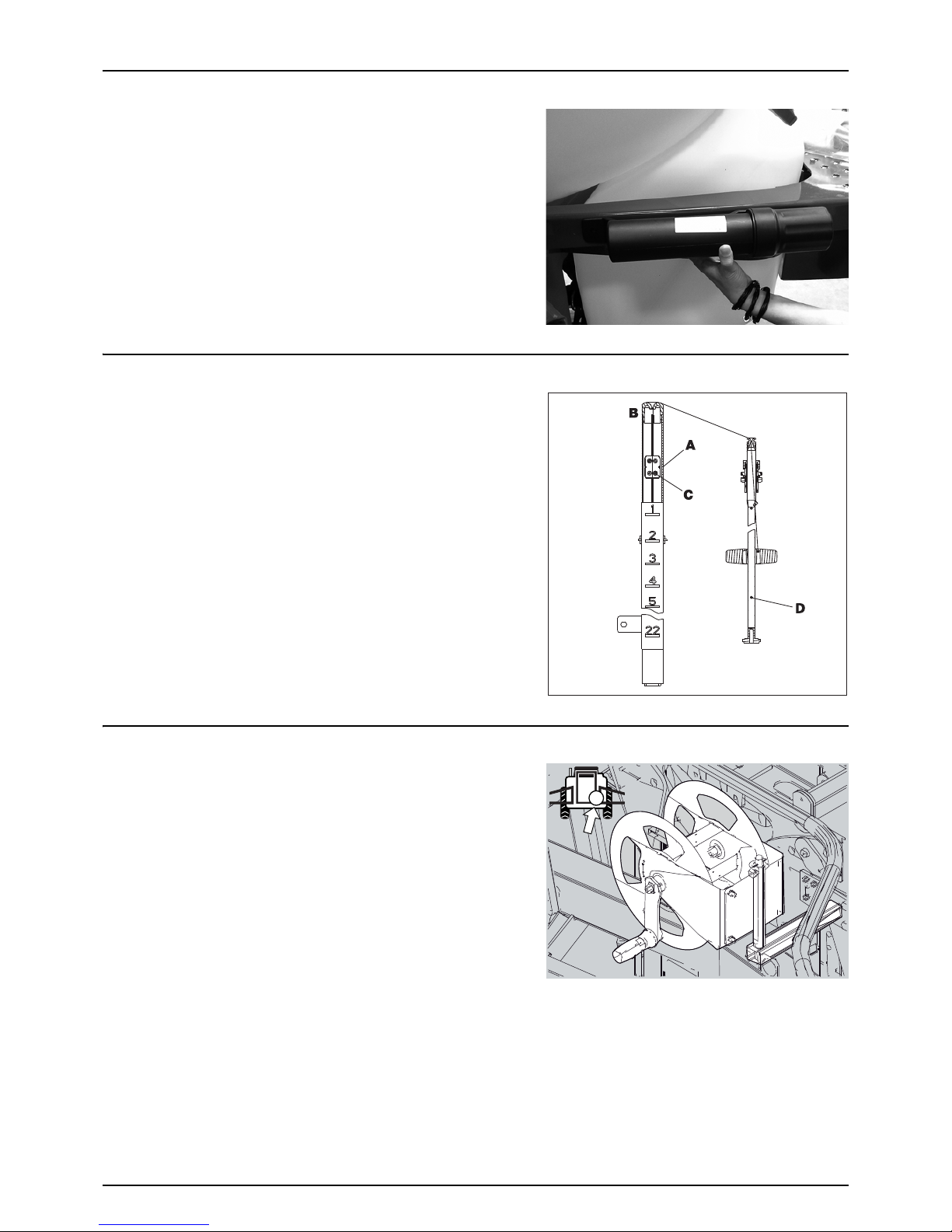
3. If the transmission shaft needs to be shortened, pull the shaft
apart. Fit the two shaft parts to the tractor and the sprayer pump
and measure how much the shaft needs to be shortened. Also
mark the protection guards with the same length to be shortened.
±
WARNING! Only shorten the shaft if it is absolutely necessary!
±
WARNING! The shaft must always have minimum overlap of half a shaft length!
The recommended overlap (A) of the two shaft parts is 2/3 of the length.
The shaft must always have minimum overlap (A) of 1/2 of the length.
Page 36

4 - Sprayer Setup
36
Mechanical connections
Quick Hitch
The sprayer is designed for a three point suspension (Category II). A quick hitch is supplied with the sprayer. Fit the quick
hitch to the tractor for easy hook-up of the sprayer.
±
WARNING! When hooking up the sprayer, ensure that the safety hooks are fully engaged before driving.
Page 37

4 - Sprayer Setup
37
Hydraulic systems
General Info
Ensure that the snap couplers are clean before connection!
After having operated the boom and the system has been filled with oil, check the tractor’s hydraulic oil level and top up, if
necessary.
€
DANGER! Test of the hydraulic system should be done very cautiously. There may be air trapped in the system which
can cause violent movements of the boom.
€
DANGER! Hydraulic leaks: Never use your fingers to locate a leakage in any part of the hydraulic system. Due to high
pressure, hydraulic oil may penetrate the skin.
Requirements for Tractor
The hydraulic system requires:
• One double-acting outlet for the electro-hydraulic operation of the boom functions.
Models without electrical activated boom lift also require:
• One single-acting outlet to raise and lower the boom.
μ
ATTENTION! The hydraulic hoses are marked with arrows to indicate the direction of oil flow.
μ
ATTENTION! The hydraulic system requires an oil flow between 25 and 130 l/min and a minimum pressure of 180 bar.
±
WARNING! All hoses MUST be connected. Ensure snap couplers are thoroughly clean before connection. Failure to do
so will cause premature wear to the blower hydraulics.
Closed Centre Hydraulics
The sprayer is delivered for use with open centre hydraulic
systems. If the tractor is equipped with closed centre (load sensing)
hydraulics, the bypass on the hydraulic valve block on the sprayer
needs to be blocked off.
The sprayer is supplied
with an extra 1/2” brass nipple with no
perforation.
To convert the sprayer for closed centre hydraulics:
1. Disconnect hydraulic hose A
2. Swap standard 1/2” black nipple B with brass nipple C
3. Connect hydraulic hose A.
Page 38

4 - Sprayer Setup
38
Open Centre Hydraulics
The open centre hydraulics block is necessary, if the tractor uses open centre hydraulics and/or load sensing.
Model without electrical activated boom lift
The valve is factory set for open centre hydraulics, but if closed centre
hydraulics is used (also in combination with load sensing), screw in the
valve (clockwise).
±
WARNING! Before operating the hydraulics, the valve should be
set according to the specific tractor model. If you are unsure of
the type of hydraulic system in your tractor, please contact your
tractor dealer.
±
WARNING! Always be sure to fully open or close the open/closed centre selection valve. Failure to do so may cause
damage to vital pump parts.
Load sensing hydraulics
Certain tractor models are able to use Load Sensing using an external sensing line (1/4” hose) directly from the tractor to the
boom hydraulic block. If fitted, the LS outlet on the boom hydraulic block must be restricted using an 1/4” nipple with an
0.7 mm orifice (HARDI item no. 146851).
Model with electrical activated boom lift
The valve (1) is factory set for open centre hydraulics, but if closed centre
hydraulics is used (also in combination with load sensing) then screw in
the valve (clockwise).
Certain tractor models are able to use Load Sensing without connecting
an external sensing line. But if optimal sensing control pressure cannot
be obtained, an external sensing line needs to be connected (3). Please
consult your tractor dealer for correct setup and correct connection.
Before operating the hydraulics, the valve should be adjusted according
to the specific tractor model. If you have doubt about which type of
hydraulic system your tractor is equipped with, please consult your
tractor dealer.
Combinations of settings for flow element and circuit value:
*if the tractor requires pressure relief, contact your tractor dealer for further advice.
±
WARNING! Always be sure to fully open or close the open/closed centre selection valve (1). Failure to do so may cause
damage to vital pump parts.
WARNING! It is essential that connectors on the sensing line are kept totally clean. Failure to do so may result in impurities
entering the pump and causing damage to vital pump parts.
Valve no. 123 (LS port)
Open centre Out Out Not connected
Closed centre In In Not connected
Load sensing (LS) In Out* Connected
L
Page 39

4 - Sprayer Setup
39
Electrical Connections
Installation of Control Unit Brackets
Find a suitable place in the tractor cabin to mount the control units. Best
recommended position is to the right of the driver seat.
The supplied tractor pillar bracket (A) has a hole spacing of 100 and 120
mm, which fits most tractors. Threaded mounting holes may be hidden
behind front corner cover. Check the tractor’s instruction book for
information regarding attachment points.
Three mounting tubes (B) are supplied. One, two or all three may be
used. They can be bent and shortened. A spacer (C) is also supplied to
allow further attachment possibilities. Find the best solution for your
tractor or vehicle.
Tube (B) plate is staggered so that, if correctly orientated, all boxes will
line up.
μ
ATTENTION! See also the controllers instruction book for further
details of fitting the controller equipment.
Power Supply
Power requirement is 12V DC. Always note polarity! For proper function
of the electric equipment, the wires must have the following
recommended cross sectional areas and correct fuses to ensure a
sufficient power supply.
The delivered power connectors follows the standard of most modern
tractors. If you have a tractor with another power connector, it is
necessary to disassemble the connector and fit it to the actual tractor
connector.
The number and the type of connectors may vary on the specific
sprayer, depending on its equipment.
Cigar connector
Spray control unit requires:
Wire 2.5 mm
2
, Fuse 10 Amp
Hydraulic control unit requires:
Wire 4.0 mm
2
, Fuse 16 Amp
7-Pole traffic light connector
100 -120mm
A
B
C
Page 40

4 - Sprayer Setup
40
Speed Transducer for Tractor
Note the following if the speed transducer is fitted to the tractor.
The speed transducer (A) and the speed ring should be located at the
inside of the tractor’s right wheel. The sensor is an inductive type that
requires a metallic protrusion (e.g. a bolt head) passing by in order to
trigger a signal. It should be adjusted, so that the transducer is placed to
the centre of the holes in the speed ring (vertical direction).
Recommended distance between protrusion and transducer (A) is 3 to
6 mm. Check this in the entire circumference.
Correct fitting is indicated by a constant flashing of the transducer, when
the wheel is rotating.
Road Safety Kit
The sprayer can be equipped with rear lights. Connect the plug for rear lights to the tractor’s 7-pin socket and check the
function of rear lights, stop lights, side lights and direction indicators on both sides before driving.
The wiring is in accordance with ISO 1724. See the section “Technical Specifications”.
μ
ATTENTION! Turn OFF all work lights when driving on public roads!
Page 41

4 - Sprayer Setup
41
Liquid system
Self-Cleaning Filter - Choice of Restrictor
It is important to have a large flow through the filter. This is achieved by
choosing the restrictor size in relation to the liquid consumption of the
spray boom. 4 restrictors are supplied. Use the green one with largest
orifice (A) first.
Remove the hose (N) from the filter. Be careful not to loosen the seal.
Place the restrictor in the hose and mount the hose again.
If the required working pressure cannot be obtained, the restrictor is too
large. Choose a smaller restrictor. Start with a black one, then a white and
finally a red one.
When cleaning the filter, remove the hose (N) and the hose at the safety
valve and check that there are no residues.
Standard filter size is 80 mesh. Filters of 50 and 100 mesh are available
and can be changed by opening the filter top.
Check the condition of the O-rings before reassembly and replace them
if damaged.
Adjustment of EVC Operating Unit
Adjust the EVC operating unit before spraying, using only clean water
(without chemicals).
1. Choose the correct nozzle for the spray job by turning the TRIPLET
nozzle bodies. Make sure that all nozzles are of the same type and
capacity. See the “Spray Technique” book.
2. Set the main ON/OFF switch to ON at the spray control unit.
3. Turn all distribution valve switches ON at the spray control unit.
4. Press down the pressure regulation switch at the spray control unit
until the emergency handle on the valve stops rotating (minimum
pressure).
5. Put the tractor in neutral and adjust the PTO and thereby the
number of revolutions of the pump corresponding to the intended travelling speed. Remember to keep the number
of revolutions of the PTO between 300-600 rpm (pump 540 rpm) or 650-1100 rpm (pump 1000 rpm).
6. Push up the pressure regulation switch at the spray control unit, until the required spray pressure is shown on the
pressure gauge.
Adjustment of pressure equalization:
7. Close the first section valve on the spray control unit.
8. Turn the adjusting screw for the corresponding valve, until the pressure gauge shows the same pressure as when all
sections were open.
9. Open the section valve again.
10. Adjust the next section valves in the same way.
μ
ATTENTION! Hereafter adjustment of pressure equalization will only be needed when:
• you change to nozzles with other capacities
• the nozzle output increases, as the nozzles wear out
Page 42

4 - Sprayer Setup
42
BoomPrime Adjustment
The BoomPrime system (optional) works within a fixed pressure range of around 3 bar, but it must be adjusted for the specific
spray job (different choice of nozzles etc.):
1. Unfold the boom and start the PTO.
2. Set pressure valve to “Spraying”, suction valve to “Main tank” and
agitation valve to “Agitation”.
3. Adjust the spray pressure to what will be used when spraying.
4. Turn the BoomPrime adjuster screw (A) to increase the BoomPrime
pressure to 3 bar or until the nozzles start to leak.
5. If nozzles leak, then lower the BoomPrime pressure by 1 bar on the
adjuster screw (A).
μ
ATTENTION! If not adjusted correctly, nozzles will not close (i.e.
will leak) when the spraying is stopped or it will not prime the
tubes.
The possible priming circulation speed of BoomPrime relies on the nondrip valves to keep the nozzles closed. If an extended amount circulation
may be necessary, the non-drip valves can be changed to a version with
higher pressure setting (later opening time).
Non-Drip Valve Open (bar)
Green (standard) 0.5
Yellow 0.7
A
Page 43

4 - Sprayer Setup
43
Spray Boom
Suspension Effect Adjustment
In order to adjust the behaviour of the boom, the trapeze has 4 settings.
How to change the setting
1. Unfold and support the centre section (X).
2. Loosen the locking bolt (A).
3. Remove the cross pin + split pin (B).
€
DANGER! Do not remove the cross pin, unless the boom is fully
supported in a safe way!
4. Place (B) in new setting position (1-4).
5. Fasten bolt in locking hole (A) again.
μ
ATTENTION! The locking bolt is mounted in the opposite hole
from the cross pin + split pin. Locking bolt in position A, when
using hole 1 or 2, and locking bolt in position C, when using hole
3 or 4.
Carry out similar adjustments to both sides of the trapeze.
Setting Behavior
1 For use on uneven ground with many obstacles.
2 All-round standard setting (Factory setting).
3 Slightly slower moving trapeze. Good at following slopes, but less
compensating for obstacles.
4 Very slow moving trapeze. For use on even ground and slopes where
there are no obstacles.
Page 44

4 - Sprayer Setup
44
Page 45

45
5 - Operation
Spray Boom
Safety Info
The boom must not be folded/unfolded while driving! Never use the folding/unfolding functions before the sprayer has
been stopped! Failure to do so will damage the boom.
€
DANGER! Before unfolding the boom it is important to connect the sprayer to the tractor to prevent overbalancing
of the sprayer.
€
DANGER! When folding or unfolding the boom, make sure that no persons or objects are within the operating area
of the boom.
€
DANGER! Always follow the guidelines listed below when driving in areas with overhead power lines:
Never use the folding/unfolding functions in areas with overhead power
lines.
Unintended boom movements may cause contact with overhead
power lines.
μ
ATTENTION! A label (HARDI item no. 978448) follows the sprayer.
This label must be placed in the cabin visible from the operator’s
seat.
μ
ATTENTION! Only unfold and fold the boom on level ground.
Page 46

5 - Operation
46
Manoeuvring of the Boom
÷
NOTE! Manoeuvring instructions for booms WITHOUT electrically activated boom lift.
The switches on the hydraulic control box control the following
functions:
1. Power ON/OFF
2. Trapeze lock
3. Boom tilt left
4. Boom tilt right
5. Boom slanting
6. Boom folding left
7. Boom folding right
±
WARNING! Ensure that the trapeze lock is locked before using the folding functions.
±
WARNING! The folding functions must only be operated when the sprayer is stationary! Failure to do so will damage
the boom.
±
WARNING! Do not tilt the boom to vertical without folding. Neither during normal folding procedure. This may cause
damage to the boom.
To unfold the boom do the following in consecutive order:
1. Check that the trapeze lock (2) is locked.
2. Activate the tractor’s hydraulic control lever to lift the boom clear of the transport brackets.
3. Push the switches (3) and (4) downwards to lower individual tilt rams.
4. Push the switches (6) and (7) outwards to unfold the boom.
5. Activate the tractor’s hydraulic control lever to lower the boom to correct height above crop or ground level.
To fold the boom do the following in consecutive order:
1. Push switch (5) to set neutral slant angle (no slant).
2. Check that the trapeze lock (2) is locked.
3. Activate the tractor’s hydraulic control lever to raise the boom to the highest possible position.
4. Push switch (6) to the right and switch (7) to the left to fold the boom, i.e. against each other.
5. Push the switches (3) and (4) upwards to raise the individual tilt rams. Make sure to fold the boom against the slide
pads.
6. Activate the tractor’s hydraulic control lever to lower the boom until it rests on the transport brackets.
Page 47

5 - Operation
47
Manoeuvring of the Boom
÷
NOTE! Manoeuvring instructions for booms WITH electrically activated boom lift.
The switches on the hydraulic control box control the following
functions:
1. Power ON/OFF
2. Trapeze lock
3. Boom tilt left
4. Boom raise/lower
5. Boom tilt right
6. Boom slanting
7. Boom folding left
8. Boom folding right
±
WARNING! Ensure that the trapeze lock is locked before using the folding functions.
±
WARNING! The folding functions must only be operated when the sprayer is stationary! Failure to do so will damage
the boom.
±
WARNING! Do not tilt the boom to vertical without folding. Neither during normal folding procedure. This may cause
damage to the boom.
To unfold the boom do the following in consecutive order:
1. Check that the trapeze lock (2) is locked.
2. Push switch (4) upwards to lift the boom clear of the transport brackets.
3. Push the switches (3) and (5) downwards to lower individual tilt rams.
4. Push the switches (7) and (8) outwards to unfold the boom.
5. Push switch (4) downwards to lower the boom to the correct height above crop or ground level.
To fold the boom do the following in consecutive order:
1. Push switch (6) to set neutral slant angle (no slant).
2. Check that the trapeze lock (2) is locked.
3. Push switch (4) upwards to raise the boom to the highest possible position.
4. Push switch (7) to the right and switch (8) to the left to fold the boom, i.e. against each other.
5. Push the switches (3) and (5) upwards to raise the individual tilt rams. Make sure to fold the boom against the slide
pads.
6. Push switch (4) downwards to lower the boom until it rests on the transport brackets.
1
3
4
5
6
78
2
Page 48

5 - Operation
48
Liquid System
Filling/Washing Location Requirements
When filling the sprayer with chemicals and water, it is important to avoid spot contamination by spraying chemicals in
order to protect the subsoil water resources.
At a dedicated filling site
If the sprayer is always filled on the same location, a special filling/washing location should be established. This should have
a hard, liquid-impenetrable surface (e.g. concrete) securing against seepage, together with edges securing against run-off
to the surrounding areas. The location should be drained to an adequate receptacle (e.g. slurry tank or similar).
Any spillage or washings should be retained and diluted in order to be distributed in a larger area. This is to ensure minimal
environmental impact and avoid build-up of larger chemical concentrations at one spot.
If no other requirements of distances exist, the following general recommendation of distance can be used. Filling location
must be no closer than:
1. 50 metres from public water supplies for drinking purposes, and
2. 25 metres from non-public water supplies for drinking purposes and from treatment sumps and cesspools of drainage
systems, and
3. 50 metres from surface water (watercourses, lakes and coastal waters) and from nature reserves.
In the field
Alternatively the sprayer can be filled in the field, where the spraying is to take place. If so, choose a different location for
each refilling.
If no other requirements of distances exist, the filling should not take place closer than:
1. 300 metres from public or non-public water supplies for drinking purposes, and
2. 50 metres from surface water (watercourses, lakes and coastal waters), treatment sumps, cesspools of drainage
systems, and nature reserves.
μ
ATTENTION! Legislation and requirements vary from country to country. Always follow local legislation in force.
μ
ATTENTION! It is the responsibility of the sprayer owner/operator to comply with all relevant legislation. HARDI cannot
undertake any responsibilities for incorrect operation and use.
Filling of Water
The tank should normally be filled 1/3 with water before adding
chemicals. Always follow the instructions given on the chemical
container!
±
WARNING! If the sprayer is put aside with liquid in the main tank,
all manifold valves must be closed.
Page 49

5 - Operation
49
Filling Through Tank Lid
Water is filled into the tank by removing the big tank lid, which is located at the top of the tank on the sprayer’s right side.
The tank lid is accessible from the optional footboard. It is recommended to use as clean water as possible for spraying
purposes. Always fill water through the strainer basket to prevent foreign particles from entering the tank. An overhead tank
can be used in order to obtain high filling capacity.
±
WARNING! Do not let the filling hose enter the tank. Keep it
outside the tank, pointing towards the filling hole. If the hose is
led into the tank, and the water pressure drops at the water
supply plant, chemicals may be sucked back and contaminate
the water supply lines, supply plant and supply well.
±
WARNING! The water supply line should be provided with a check
valve as additional safety precaution. Follow local legislation in
force at any time.
±
WARNING! The water supply should be provided with a water meter to avoid spillage by overfilling. Follow local
legislation in force at any time.
Filling of Rinsing Tanks
Two rinsing tanks are fitted to the sprayer, they are filled via the lid on the
top of the tanks:
1. Remove the filler lid of the tank to be filled.
2. Fill water into the tank. Keep an eye on the tank opening in order
not to overfill the tank.
3. Stop filling and refit the lid.
Volume: approximately 80 litres each.
μ
ATTENTION! Only fill rinsing tank with clean water! To avoid algae
developing in the rinsing tank, always drain this tank, if the
sprayer is not in use for a longer period of time.
Filling of Clean Water Tank
To fill the clean water tank:
1. Remove the tank lid
2. Fill with clean water
3. Reposition the tank lid.
For use of water:
• Turn the ball valve lever to open (arrow).
The water from this tank is for hand washing, cleaning of clogged
nozzles etc.
μ
ATTENTION! Only fill this tank with clean water! To avoid algae
developing in the clean water tank, always drain this tank, if the
sprayer is not in use for a longer period of time.
±
WARNING! Although the clean water tank is only filled with clean
water, this water must NOT be used for drinking.
Page 50

5 - Operation
50
External Filling Device (optional)
The External Filling Device is operated as follows:
1. Remove cover and connect suction hose to the suction manifold.
2. Turn pressure valve to ” Spraying”, and, if the blue return valve is
mounted, turn it to “Main tank”.
3. Close suction valve for Main tank/RinseTanks.
4. Turn handle on External Filling Device valve towards Filling Device.
5. Engage diaphragm pump and set PTO revolutions at 540 rpm.
6. The tank is now filled with water. Keep an eye on the liquid level
indicator.
7. Turn handle on suction manifold away from Filling Device to discontinue filling process. Now disengage the pump.
8. Disconnect suction hose and replace cover.
€
DANGER! Prevent contamination or injury. Do not open suction valve towards Filling Device, unless the pump is
running and the filling hose is connected. If this valve is opened without the pump running, liquid will stream out of
the coupler.
±
WARNING! Do not leave the sprayer while filling the tank, and keep an eye on the level indicator in order NOT to
overfill the tank.
μ
ATTENTION! Observe local legislation regarding use of filling device. In some areas, it is prohibited to fill from open
water reservoirs (lakes, rivers etc.). It is strongly recommended only to fill from closed reservoirs (mobile water tanks
etc.) to prevent contamination.
1.
2.
3.
4.
Page 51

5 - Operation
51
Safety Precautions - Crop Protection Chemicals
Always be careful when working with crop protection chemicals!
±
WARNING! Always wear proper protective clothing before handling chemicals!
Personal protection
Depending on chemical type, protective gear/equipment should be worn to avoid contact with the chemicals, such as:
• Gloves
• Waterproof boots
• Headgear
• Respirator
• Safety goggles
• Coverall with chemical resistance
±
WARNING! Protective clothing/equipment should be used, when preparing the spray liquid, during the spray job and
when cleaning the sprayer. Follow the chemical manufacturer’s instructions given on the chemical label and/or local
legislation.
±
WARNING! It is always advisable to have clean water available, especially when filling the sprayer with chemicals.
±
WARNING! Always clean the sprayer carefully and immediately after use.
±
WARNING! Only mix chemicals in the tank according to directions given by the chemical manufacturer.
±
WARNING! Always clean the sprayer before changing to another chemical.
Page 52

5 - Operation
52
Filling Liquid Chemicals by using HARDI TurboFiller
1. Fill the main tank at least 1/3 with water (unless otherwise stated
on the chemical container label).
2. Turn the handle of the suction valve towards “suction from Main
tank”. Turn pressure valve to“TurboFiller”. Close the AgitationValve.
μ
ATTENTION! If filling water from an external tank, this can be
continued while doing the next steps.
3. Engage the pump and set PTO speed at 540 rpm.
4. Open TurboFiller lid. Measure the correct quantity of chemical and
fill it into the hopper.
€
DANGER! Always wear face shield and other appropriate personal
safety equipment, when filling chemicals.
μ
ATTENTION! The scale in the hopper can only be used, if the sprayer is parked on level ground! It is recommended to
use a measuring jug for best accuracy.
5. Engage the hopper transfer device by opening the TurboFiller suction valve to transfer chemicals to the main tank.
The TurboFiller suction valve must be open for at least 20 seconds after the chemical is no longer visible in the hopper,
in order to empty the transfer hoses completely into the main tank.
€
DANGER! If the TurboFiller and the transfer hoses are not completely emptied, there is a risk of chemicals being
sucked out of the main tank!
6. If the chemical container is empty, it can be rinsed by the Chemical Container Cleaning device. Place the container
over the multi-hole nozzle and push the container for cleaning.
€
DANGER! In order to avoid spray liquid hitting the operator, do not press the lever, unless the multi-hole nozzle is
covered by a container, as spray liquid may otherwise hit the operator!
μ
ATTENTION! The rinsing device uses spray liquid to rinse containers for concentrated chemicals. Before disposal,
always rinse the chemical containers with clean water several times, until they are clean.
7. Flush the TurboFiller with clean water from the rinsing tank or from an external tank by shifting to suction. The
TurboFiller suction valve must be open for at least 20 seconds after the rinse water is no longer visible in the hopper,
in order to empty the transfer hoses completely into the main tank.
μ
ATTENTION! If not flushed with clean water, the hopper rinsing device uses spray liquid for rinsing the hopper!
Cleaning the TurboFiller must always be done, when the spray job is ended, and together with cleaning the entire
sprayer. A cleaning after the last filling, and before spraying, does not ensure a clean TurboFiller!
8. Close the TurboFiller suction valve, when the hopper has been rinsed. Close the lid.
9. Turn the AgitationValve towards “Agitation”.
Page 53

5 - Operation
53
10. When the spray liquid is well agitated, turn handle of the pressure
valve towards “Spraying” position. Keep PTO engaged, so that the
spray liquid is continuously agitated, until it has been sprayed on
the crop.
μ
ATTENTION: If foaming is a problem, turn down the agitation.
Filling Powder Chemicals by using HARDI TurboFiller
1. Fill the main tank at least 1/2 with water (unless otherwise stated
on the chemical container label). See section “Filling of water”.
2. Turn the handle of the suction valve towards “suction from Main
tank”. Turn pressure valve to“TurboFiller”. Turn the AgitationValve
towards “Agitation” if required. Close remaining valves.
μ
ATTENTION! For increased suction from the TurboFiller the
AgitationValve can be kept closed.
μ
ATTENTION! If filling water from an external tank, this can be
continued while doing the next steps.
3. Engage the pump and set PTO speed at 540 rpm.
4. Open TurboFiller lid. Open TurboDeflector valve and TurboFiller suction valve.
5. Measure the correct amount of powdered chemical and sprinkle it into the hopper as fast as the transfer device can
flush it down. The TurboFiller suction valve must be open for at least 20 seconds after the chemical is no longer visible
in the hopper in order to completely empty the transfer hoses into the main tank.
€
DANGER! If the TurboFiller and the transfer hoses are not completely emptied, there is a risk of chemicals being
sucked out of the main tank!
€
DANGER! Always wear face shield and other appropriate personal safety equipment, when filling chemicals.
6. If the chemical container is empty, it can be rinsed by the Chemical Container Cleaning device. Place the container
over the multi-hole nozzle and push the upper lever to the left of the TurboFiller.
€
DANGER! In order to avoid spray liquid hitting the operator, do not press lever unless the multi-hole nozzle is covered
by a container, as spray liquid may otherwise hit the operator!
μ
ATTENTION! The rinsing device uses spray liquid to rinse containers for concentrated chemicals. Always rinse the
chemical containers with clean water several times, until they are clean before disposal.
Page 54

5 - Operation
54
7. Flush the TurboFiller with clean water from the rinsing tank or from an external tank by shifting to suction. The
TurboFiller suction valve must be open for at least 20 seconds after the rinse water is no longer visible in the hopper,
in order to completely empty the transfer hoses into the main tank.
μ
ATTENTION! If not flushed with clean water, the hopper rinsing device uses spray liquid for rinsing the hopper!
Cleaning the TurboFiller must always be done, when the spray job is ended, and together with cleaning the entire
sprayer. A cleaning after the last filling, and before spraying, does not ensure a clean TurboFiller!
8. Close TurboFiller suction valve, when the hopper has been rinsed. Close the lid.
9. If closed, turn the AgitationValve towards “Agitation”.
10. When the spray liquid is well agitated, turn handle of the pressure
valve towards “Spraying” position. Keep PTO engaged, so that the
spray liquid is continuously agitated, until it has been sprayed on
the crop.
μ
ATTENTION! If foaming is a problem, turn down the agitation.
Page 55

5 - Operation
55
TurboFiller Rinsing
÷
NOTE! It is important to suck from the rising tank or an external
tank with clean water.
Rinse the TurboFiller and chemical containers as follows:
Cleaning empty containers - TurboFiller lid is open
1. Put container over the rotating flushing nozzle in the middle of the
TurboFiller, so that the nozzle is inside the container.
2. Simultaneously press the Chemical Container Cleaning lever and
the TurboFiller suction valve. This rinses the chemical container
with the flushing nozzle, while the rinsing liquid is emptied out of the TurboFiller.
TurboFiller rinsing - TurboFiller lid is closed
1. Close TurboFiller lid.
2. Turn the suction SmartValve towards “Rinsing tank” or “External Filling Device”, if clean water is available here.
3. Open the Turbo Deflector Valve for 1 minute to get plenty of clean water through the hoses.
4. Simultaneously press the Chemical Container Cleaning lever and the TurboFiller suction valve. This rinses the hopper
with the flushing nozzle, while the rinsing liquid is emptied out of the TurboFiller.
5. Rinse the hopper for 30-40 seconds.
6. Open the lid to inspect if the TurboFiller is empty. If not, close the lid again and press the TurboFiller suction valve, until
the TurboFiller is empty.
7. After the last flushing, the TurboFiller suction valve must be open for at least 20 seconds, after the rinse water is no
longer visible in the hopper, in order to completely empty the transfer hoses into the main tank.
μ
ATTENTION! The TurboFiller needs to be cleaned thoroughly after finishing spraying. This is to ensure that it is clean,
before spraying other crops that may be sensitive to the chemicals just used. See section “Cleaning” on page 60 for
details.
Page 56

5 - Operation
56
Operating the Control Unit While Spraying - Spray Box III
The switches of the spray control unit (Spray Box) control the following functions:
1. Power ON/OFF. Turns the Spray Box power on or off.
2. Spray pressure regulation. Regulates the main spray pressure.
3. Main valve ON/OFF. Turns all sections on or off. Lever up is OFF and down is ON.
4. Optional function (A/OFF/B). If extra equipment is added, it can be controlled from here. Middle position is OFF.
5. End nozzle (Left/OFF/Right). If end nozzles are fitted, they can be turned on for each side. Middle position is OFF.
6. Foam marker blob interval. Foam marker equipment is not included from HARDI.
7. Foam marker (Left/OFF/Right). Foam marker equipment is not included from HARDI.
8. Section valves. Turns individual spray sections on or off. Lever up is OFF, and lever down is ON.
• In order to close the entire boom, switch main ON/OFF (3) to OFF position. This returns the pump output to the tank
through the return system. The diaphragm non-drip valves ensure instantaneous closing of all nozzles.
• In order to close one or more sections of the boom, switch the relevant distribution valve (7) to off position (upwards).
The pressure equalization ensures that the pressure does not rise in the sections, which remain open.
• On the sprayer the suction valve should be turned toward “Suction from Main tank” and the pressure valve should be
turned toward “Spraying”. Turn the agitation valve to “Agitation” if necessary.
1
2
3
8
7
6
5
4
Page 57

5 - Operation
57
Dilution of Spray Liquid
Use the dilution functions in the following way:
Tank dilut ion
When the main tank is empty, and the spray liquid composition is going
to be changed, the residual fluid in the tank must be diluted before
driving back to the farm for refilling.
1. Turn Off the main On/Off.
2. Flick the dilution switch to “tank dilution” (A).
3. Fill approximately 1/3 of the rinsing tank content into the main tank.
4. Flick the dilution switch back to “spraying” (B). Leave the switch here
for at least 30 seconds.
5. Turn On the main On/Off and begin driving in the field to spray out the diluted spray liquid.
6. While spraying the diluted liquid, turn the main On/Off to Off and then On again shortly. This also dilutes the boom
equalization piping.
7. Repeat step 1-6 two more times (until the rinsing tank is empty).
Boom dilution
When spraying work is being interrupted or finished, the boom piping
must be diluted before driving back to the farm.
1. Continue driving in the field while leaving the main On/Off On.
2. Flick the dilution switch to “boom dilution” (C).
3. Empty out approximately 1/2 of the rinsing tank content into the
field through the boom.
4. Turn off the PTO to stop the dilution of the boom piping.
5. Flick the dilution switch back to “spraying” (B) to be ready for resuming spraying later.
6. Turn main On/Off to Off and drive home.
÷
Do not turn the main On/Off to Off while diluting the boom piping, as the remaining spray liquid in the main tank
will then be diluted.
Before Returning to Refill the Sprayer
If the sprayer is to be refilled at the farm, or at a fixed filling place without a filling space with hard surface and drain to a
closed reservoir, the sprayer should be rinsed before returning to refill.
Dilute the residues of the spraying circuit, and spray it on the crop. Now rinse the sprayer on the outside with the External
Cleaning Device (optional equipment), before returning to the farm.
±
WARNING! Always follow local legislation in force at any time.
A
B
C
A
B
C
Page 58

5 - Operation
58
Agitation Before Resuming a Spray Job
If a spray job has been interrupted for a while, severe sedimentation may
occur depending on the chemicals being used. Before resuming the
spray job, it might be necessary to agitate sediment material.
1. Turn the handle at the suction valve towards “Suction from main
tank”. Turn the pressure valve to closed position and turn the
agitation valve towards “Agitation”. Other valves are closed.
2. Engage the pump and set PTO speed to 540 rpm.
3. Agitation has started and should be continued for at least 10
minutes.
€
The spray job can now be resumed. Turn pressure valve towards
“Spraying” and start spraying.
Parking the Sprayer
To avoid spot contamination, the sprayer should always be parked at either the washing/filling location or under roof.
This prevents rainfall from washing down chemical residues from the sprayer's surfaces.
• Parking at the washing/filling location will retain residues.
• Always park the machine out of reach of children, animals and unauthorized persons.
BoomPrime
The BoomPrime system works automatically, and it is activated, when a spray job is prepared:
1. Unfold the boom and turn on the PTO.
2. Set pressure valve to “Spraying”, suction valve to “Main tank” and
agitation valve to “Agitation”, if needed.
3. Adjust the spray pressure to what will be used when spraying.
4. The boom will then be fully primed within 1-2 minutes.
If the nozzles start to leak, when closing one or more sections during a
spray job, proceed as follows:
1. Adjust the pressure on the BoomPrime pressure regulation.
2. Turn pressure valve to “Main tank”.
3. Disconnect the PTO.
If adjustment of the BoomPrime system might be necessary, please refer to “BoomPrime Adjustment” on page 42.
Page 59

5 - Operation
59
Quick Reference - Operation
In the following diagrams the handle positions for different options are described.
1
2
3
4
Page 60

5 - Operation
60
Cleaning
General Info
In order to derive full benefit from the sprayer for many years, the following service and maintenance program should be
followed.
μ
ATTENTION! Always read the individual paragraphs. Read instructions for service/maintenance jobs carefully before
starting on the job. If any portion remains unclear, or if it requires facilities which are not available, then please leave
the job to your HARDI dealer’s workshop for safety reasons.
μ
ATTENTION!
Clean sprayers are safe sprayers.
Clean sprayers are ready for action.
Clean sprayers cannot be damaged by pesticides and their solvents.
Guidelines
• Read the whole chemical label. Take note of any particular instructions regarding recommended protective clothing,
deactivating agents, etc. Read the detergent and deactivating agent labels. If cleaning procedures are given, follow
them closely.
• Be familiar with local legislation regarding disposal of pesticides washings, mandatory decontamination methods, etc.
Contact the appropriate authority if you are in doubt.
• Pesticide washings can usually be sprayed out on the field just sprayed or at a suitable cultivated area. Avoid emptying
the washings at the same spot every time and keep sufficient distance to the water environment. You must prevent
seepage or runoff of residue into streams, watercourses, ditches, wells, springs, etc. The washings from the cleaning
area must not enter sewers. Alternatively the washings can be retained in an appropriate receptacle, diluted and
distributed over a larger cultivated area - see also “Filling/Washing Location Requirements” on page 48.
• Cleaning starts with the calibration, as a well calibrated sprayer will ensure the minimal amount of remaining spray
liquid.
• It is good practice to clean the sprayer immediately after use, and thereby rendering the sprayer safe and ready for the
next pesticide application. This also prolongs the life of the components. It is strongly advised to perform an internal
cleaning of the sprayer, when high concentrations of acids or chloride are present in the active ingredients, or if the
spray liquid is corrosive. For the best result, use a cleaning agent recommended by HARDI, e.g. AllClearExtra.
• It is sometimes necessary to leave spray liquid in the tank for short periods, e.g. overnight, or until the weather becomes
suitable for spraying again. Unauthorized persons, children and animals must not have access to the sprayer under
these circumstances.
• If the product applied is corrosive, it is recommended to coat all metal parts of the sprayer before and after use with a
suitable rust inhibitor.
• The sprayer must always be parked under roof to avoid rain washing off pesticides as well as build-up of spot
contamination in the soil. If parked outside, the sprayer should be parked on the filling/washing location in order to
retain possible pesticides.
Page 61

5 - Operation
61
Quick Reference - Cleaning
In the following diagrams handle positions for different options are described.
Page 62

5 - Operation
62
Cleaning the Tank and Liquid System
μ
ATTENTION! Thorough cleaning of the sprayer is to be carried out when shifting to crops, which are very sensitive to
chemicals just sprayed, or prior to storage for a longer period of time.
÷
NOTE! Prior to the described cleaning, a standard cleaning should be carried out.
• Select and use the appropriate protective clothing. Select detergent suitable for cleaning and suitable deactivating
agents if necessary.
• Rinse and clean sprayer and tractor externally. Use detergent if necessary.
1. Remove tank filters and suction filters and clean the sprayer. Be careful not to damage the filter mesh. Put back the
suction filter top. Put back all filters, when the sprayer is completely clean.
2. With the pump running, rinse the inside of the tank. Do not forget to clean the tank roof. Rinse and operate all
components and any equipment, which have been in contact with the chemical. Before opening the distribution
valves and spraying the liquid out, decide whether this should be done in the field or on the seepage location.
3. After spraying the liquid out, stop the pump and fill at least 1/5 of the tank with clean water. Note that some chemicals
require the tank to be completely filled. Add appropriate detergent and/or deactivating agent, e.g. washing soda or
triple effect ammonia. Special detergents for sprayer cleaning is recommended as some also lubricate ball valves etc.
4. Start the pump and operate all controls enabling the liquid to come into contact with all the components. Operate
the distribution valves as the last thing. Some detergents and deactivating agents work best, if they are left in the tank
for a short period. Check the label.
5. Drain the tank and let the pump run dry. Rinse inside of the tank, again letting the pump run dry.
6. Stop the pump. If the pesticides used have a tendency to block nozzles and filters, remove and clean them
immediately.
7. Put back all the filters and nozzles and store the sprayer. If it is noted, from previous experiences, that the solvents in
the pesticides are particularly aggressive, store the sprayer with the tank lid open.
μ
ATTENTION! It is advisable to increase the forward speed (double, if possible) and reduce the spraying pressure to 1.5
bar, when spraying diluted remaining liquid in the field just sprayed.
μ
ATTENTION! If a cleaning procedure is given on the chemical label, follow it closely.
μ
ATTENTION! If the sprayer is cleaned with a high pressure washer, lubrication of the entire machine is recommended.
Cleaning and Maintenance of Filters
Clean filters ensure:
• Sprayer components such as valves, diaphragms and operating units are not hindered or damaged during operation.
• Nozzle blockades do not occur whilst spraying.
• Long life of the pump. A blocked suction filter will result in pump cavitation. The main filter protecting sprayer
components is the suction filter. Check it regularly.
Page 63

5 - Operation
63
Use of Rinsing Tank(s) and Rinsing Nozzles
The integrated rinsing tank(s) can be used for two different purposes.
μ
ATTENTION! If a cleaning procedure is given on the chemical label, follow it closely.
In-field diluting before cleaning
In-field diluting of remaining spray liquid residue in the spraying circuit should be carried out, before cleaning the sprayer.
Rinsing the main tank and liquid system:
1. Empty the sprayer as much as possible. Close the AgitationValve (no agitation) and spray until air comes out of all
nozzles.
2. Turn suction valve towards and pressure valve towards . Set blue return valve to .
3. Engage the pump. Set the pump speed to approximately 300 rpm and increase the spraying pressure to 6 bar.
4. When 1/3 of the contents in the rinsing tank(s) is used, turn suction valve towards and operate all valves on the
pressure side of the system in the following order, so that all hoses and components are rinsed:
A. Turn the pressure valve towards to activate the ejector and open the TurboFiller suction valve.
B. Open the TurboDeflector valve and close it again, when clean water comes out of nozzles.
C. Close the TurboFiller lid. and squeeze the Chemical Container Cleaning grip to clean this device.
D. Open the TurboFiller lid again, and make sure that the TurboFiller is empty.
E. When empty, close the TurboFiller suction valve again. Take care that the External fast filling connection and the
line are not contaminated with chemicals.
5. Turn the suction valve towards and the pressure valve towards , and spray the liquid in the field just sprayed.
Cleaning of Main Tank:
6. Turn the suction valve towards and the pressure valve towards . Remove the filling strainer to avoid any
cleaning shadows behind it.
7. When another 1/6 of the contents in the rinsing tank(s) is used, turn the suction valve towards .
8. Turn pressure valve towards , and spray the liquid in the field just sprayed.
9. Repeat step 6 - 8 one more time.
±
WARNING! When critical chemicals (like sulphonylurea) have been used, or a cleaning detergent is recommended, do
an extra cleaning:
10. Fill the rinsing tank(s) again.
11. Fill the main tank to 1/3 of capacity (up to 500 litres) of clean water. See section “Suction filling Device” for filling
procedure.
12. Add the cleaning detergent to the main tank by using the TurboFiller. Follow instructions on the label of the cleaning
agent.
13. Clean the whole system again.
14. To get the best cleaning effect, the Self-Cleaning Filter and the Suction Filter sieves should be washed with clean water.
15. Rinse the sprayer with clean water afterwards.
μ
ATTENTION! The rinsing nozzles cannot always guarantee a 100% cleaning of the tank. Always clean manually with a
brush afterwards, especially if crops, which are sensitive to the chemical just sprayed, are to be sprayed afterwards!
Page 64

5 - Operation
64
Rinsing when main tank is not empty
Rin sing t he pum p, o perat ing u nits, spra y lin es, e tc. in cas e of st op in spray ing (e.g . bec ause of rai n), be for e mai n tank is em pty.
Cleaning of the liquid system:
1. Turn suction valve towards . (Keep pressure valve in -position). Close Self-Cleaning filter, if possible.
2. Close AgitationValve (no agitation).
3. Engage the pump. Set the pump speed to approximately 300 rpm and increase the spraying pressure to 6 bar. Spray
the water from the rinsing tank into the field, until all nozzle tubes and nozzles have been flushed with clean water.
4. Disengage the pump.
μ
ATTENTION! It is advisable to increase the forward speed (double, if possible) and reduce the spraying pressure to 1.5
bar, when spraying diluted remaining liquid in the field just sprayed.
Cleaning the sprayer on the outside
±
WARNING! Ex ternal cleaning with a spray gun is only possible with emptied and cleaned main tank. Do a complete
main tank cleaning, before attempting to use the spray gun!
1. Turn suction valve towards and pressure valve towards . Keep other valves closed.
2. When another 1/3 of the contents in the rinsing tank(s) is used, turn the suction valve towards . Adjust the spraying
pressure to 8 - 10 bar.
3. Open the manual valve at the operating unit and wash the sprayer with the cleaning device located on sprayer’s rear
side. If neccessary, the pressure can be adjusted on the pressure regulation valve.
4. Disengage pump again.
μ
ATTENTION! If the sprayer is cleaned with a high pressure washer, lubrication of the entire machine is recommended.
Use of Detergents
It is recommended to use an appropriate cleaning detergent suitable for cleaning agricultural sprayers.
• Cleaning detergents containing a suitable lube or conditioner are recommended.
• If for some reasons this is not available, and e.g. triple ammonia water is used, it is important to rinse the spray circuit
immediately after and add some lubricant to the rinsing water to prevent ball valves etc. seizing up.
• Use of automotive antifreeze/radiator coolant (ethylene glycol) will protect valves and seals from drying or seizing up.
Technical Residue
An amount of spray liquid will inevitably remain in the system. It cannot be sprayed properly on the crop, as the pump takes
in air, when the tank is just about empty.
This technical residue is defined as the remaining amount of liquid in the system, when the first clear pressure drop appears
on the pressure gauge.
The residual dilutable volume is approx. 16 litres. See the section “Technical Specifications” for more details.
The residues in the tank should be diluted immediately in a ratio of 1:10 with clean water. Afterwards it should be sprayed
on the crop just sprayed with increased driving speed. In addition, also pump, linkage and armature can be separately rinsed
with water from the rinsing tank. However, it must be ensured that the liquid in the spray lines are in unchanged
concentration. Therefore there should be an untreated field area available to spray this liquid out.
Page 65

5 - Operation
65
Using the Drain Valve
The drain valve is operated from the right side of the sprayer’s front.
1. Pull the string to open the drain valve.
2. The valve is spring-loaded, but can be kept open by pulling the
string upwards in the V-shaped slit.
3. To release, pull the string downward and the valve will close
automatically.
If draining residues, e.g. liquid fertilizer into a reservoir, a snap coupler
with hose can rapidly be connected to the drain valve, and the liquid is
safely drained.
Page 66

5 - Operation
66
Operating Limits
The following things are important when considering the performance of the sprayer.
• Maximum driving speed
• Pressure setting
• Minimum / maximum flow rate
The operating limits for your sprayer are closely related to:
4. Pump size
5. Boom width
6. Nozzle size
In the table below, the operating limits for volume rate are calculated, when driving at different speeds.
÷
NOTE! The specified nozzle type is a standard flat fan nozzle. Other special nozzle types will show different results. Ask
your HARDI dealer if in doubt.
μ
ATTENTION! It is recommended not to drive faster than 16 km/h when spraying.
μ
ATTENTION! The pressure range for the nozzles are 1.5 - 5 bar (except for HARDI INJET nozzles, which are ranging from
3-8 bar). The spraying pressure should be within these limits.
μ
ATTENTION! In the table below, the specified combination of nozzle size and sprayer setup is not suitable, as the full
pressure range of 5 bar for the nozzle cannot be reached, when spraying the maximum volume rate (l/ha) on the crop.
This is due to the nozzle design.
÷
According to the standard for environmental requirements for sprayers, ISO 16119 / EC Directive 2009/127/EC
(amending 2006/42/EC), the farmer shall be able to use the full pressure range.
Nozzle size,
type HARDI ISO
F-110
Min. volume
ra te ( l/ h a) a t 4
km/h
Max. volume
ra te ( l/ h a) a t 4
km/h
Min. volume
ra te ( l/ h a) a t 8
km/h
Max. volume
ra te (l /h a ) at 8
km/h
Min. volume
rate (l/ha) at 12
km/h
Max. volume
rate (l/ha ) at 12
km/h
Min. volume
rate (l/ha) at 1 6
km/h
Max. volume
rate (l/ha) a t 16
km/h
02 (yellow) 171 309 86 155 57 103 43 77
025 (purple) 213 387 107 194 71 129 53 97
03 (blue) 255 465 128 233 85 155 64 116
04 (red) 339 621 170 311 113 207 85 155
05 (brown) 423 774 212 387 141 258 106 194
06 (grey) 510 930 255 465 170 310 128 233
08 (white) 678 1239 339 620 226 413 170 310
10 (light blue) 849 1548 425 774 283 516 212 387
Pump model Boom width Nozzle size
363 20 m 06 (grey)
363 20 m 08 (white)
363 20 m 10 (light blue)
363 21 m 08 (white)
363 21 m 10 (light blue)
363 24 m 06 (grey)
363 24 m 08 (white)
363 24 m 10 (light blue)
463 24 m 10 (light blue)
463 27 m 10 (light blue)
463 28 m 10 (light blue)
Page 67

5 - Operation
67
Liquid Fertilizer
Spraying pressure
If you are spraying with liquid fertilizer instead of pesticides, the spraying pressure must be increased in comparison to
pesticide spraying to get the desired output (l/ha).
The density for liquid fertilizer is normally higher than for water and spray liquids - so to get the correct output (l/ha), the
spraying pressure must be adjusted.
Example:
Nozzle output is 2.40 l/min at 3.0 bar pressure. Density of liquid fertilizer is 1.20 g/cm³.
Multiply the pressure value with the density value: 3.0 x 1.2 = 3.6; the adjusted pressure is then 3.6 bar for spraying the liquid
fertilizer.
In the table below, adjusted pressure values can be found for different densities of liquid fertilizers.
μ
ATTENTION! Pressure values below 1.5 bar or above 5.0 bar are considered to be out of range for the nozzles.
÷
NOTE! Find the density for your liquid fertilizer on the packaging or on the material safety data sheet (MSDS) included.
Additional Information
See the other book delivered from HARDI - Spray Technique - to get further information about:
• Calibration of the sprayer
• Nozzle Choice
• Nozzle Wear
• Spray Distribution
• Spray Pressure
• Water Volume Rates
• Weather Influence on Spraying
• Useful Formulae
For Optional Extras - see other books delivered or contact HARDI.
Density (g/cm³) for liquid fertilizer
1.10 1.15 1.20 1.30 1.40
Calibrated pressure (bar)
[Spraying with pesticides]
Adjusted pressure (bar)
[Spraying with liquid fertilizer]
1.5 1.7 1.7 1.8 2.0 2.1
2.0 2.2 2.3 2.4 2.6 2.8
2.5 2.8 2.9 3.0 3.3 3.5
3.0 3.3 3.5 3.6 3.9 4.2
3.5 3.9 4.0 4.2 4.6 4.9
4.0 4.4 4.6 4.8 5.2 5.6
4.5 5.0 5.2 5.4 5.9 6.3
5.0 5.5 5.8 6.0 6.5 7.0
Page 68

5 - Operation
68
Page 69

69
6 - Maintenance
Lubrication
General Info
Always store lubricants clean, dry and cool - preferably at a constant temperature - to avoid contamination from dirt and
condensed water. Keep oil filling jugs, hoppers and grease guns clean, and clean the lubricating points thoroughly before
lubricating. Avoid skin contact with oil products for longer periods.
Always follow the quality and quantity recommendations. If no quantity is recommended, feed the lubricator until new
grease becomes visible.
Pictograms in lubrication & oiling plans designate:
1. Lubricant to be used (see “Recommended lubricants” below).
2. Recommended intervals. Shown in hours or with a symbol for
occasional maintenance.
3. Amount to be used. Only shown if an amount is specified.
μ
ATTENTION! If the sprayer has been cleaned with a high pressure
washer, lubrication of the entire machine is recommended.
Recommended Lubricants
What to Lubricate? Lubricant Type Factory Use Recommended Alternatives
BALL BEARINGS and PUMP Lithium based grease
Consistency NLGI grade 2
Viscosity (@40°C) > 460 cSt
SHELL Gadus S3 V550L 1
Hardi pump grease cartridge
(400g): Item no. 28164600
MOBIL grease XHP 462
TOTAL Multis Complex SHD 460
SLIDE BEARINGS Lithium based grease
Consistency NLGI grade 1/2
Viscosity (@40°C) > 200 cSt
MOBIL XHP 222 SHELL Gadus S3 V220C 2
TOTAL Multis Complex SHD 220
OIL LUBRICATION POINTS Engine or transmission oil
Viscosity 20W-50 or 80W-90
OK Tractor UTTO GL 4 80W SHELL Spirax S4 TXM
CASTROL ACT EVO 4T
MOBIL Mobilube HD 80W/90
BOLTS Anti-corrosive wax PAVA PV 700 TECTYL 506 WD
VALVES and SEALS (O-RINGS) NSF 51, NSF 61 silicone compound DOW CORNING MOLYKOTE 111
Compound
Page 70

6 - Maintenance
70
Grease Gun Calibration
Before lubricating the sprayer, you must calibrate your grease gun to ensure that the correct amount of grease is applied to
each lubrication point. The correct amount of grease applied will prolong the lifetime of the sprayer.
Calibration example
1. Insert the correct grease cartridge in your grease gun.
2. Apply grease onto a tissue or a piece of paper. Complete 10 full
strokes of the grease gun.
3. Place the paper with grease on a scale (A).
4. If your grease pile weighs for example 10 grams, then 1 stroke
equals 1 gram of grease.
When calibrated, you can count how many strokes to complete, when
lubricating the different grease points on the sprayer according to the
specifications.
Alternative method
1. Count the strokes, until you have 10 grams of grease piled up on
the scale (A).
2. Now you can figure out how many strokes to use for applying a
certain amount of grease to a lubrication point.
Lubrication & Oiling Plan - PTO
μ
ATTENTION! The correct amount of grease applied at the intervals is important. Too little or too much grease will
shorten the lifetime of the PTO.
The amount of grease to be applied is mentioned in grams (g). Test your grease gun to see how many grams it provides, for
example after 5 strokes.
The grease points and amount of grease to be applied are shown in the pictures below together with the intervals.
Standard PTO for tractor and sprayer
A-50
A-50B-50 C-50C-50
Tractor
Sprayer
Page 71

6 - Maintenance
71
Boom Lubrication & Oiling Plan
Lift Lubrication & Oiling Plan
10
Page 72

6 - Maintenance
72
Service and Maintenance Intervals
General Info
National or regional laws may require periodic inspection of the sprayers in use. See the following section for more details.
The subsequent periodic service and maintenance work may be carried out by the user. Contact your HARDI dealer if in
doubt. If this work is completed correctly, the sprayer will run efficiently and its lifetime will be prolonged.
10 Hours Service - Spraying Circuit
Fill with clean water and operate all functions. Check for leaks using a higher spray pressure than normal. Check nozzle spray
patterns visually using clean water.
10 Hours Service - Nozzle Filters
The filters are located inside the nozzles. Check and clean.
10 hours Service - Suction Filter
To service the suction filter:
1. Pull out the steel clip (A).
2. Lift the suction hose fitting (B) from housing.
3. Filter guide and filter (C) can now be removed.
To reassemb l e :
4. Press the guide onto filter end.
5. Place the filter into housing with guide facing up.
6. Ensure the O-ring (D) on the hose fitting is in good condition and
lubricated.
7. Refit the suction hose (B) and steel clip (A).
±
WARNING! Always wear protective clothing and gloves before
opening the filter!
Page 73

6 - Maintenance
73
10 hours service - Self-Cleaning Filter
This filter should be cleaned every 10 hours.
1. Unscrew the union nut (A) and open filter.
2. Check filter gauze (B), clean if necessary.
3. Grease the O-ring (C) on the filter lid.
To reassemb l e :
4. Assemble all filter parts in the order shown on the picture.
5. Turn union nut (A) clockwise to close filter.
±
WARNING! Always wear protective clothing and gloves before
opening the filter!
10 Hours Service - InLine Filter (optional)
If the boom is equipped with In-Line Filters, unscrew the filter bowl to
inspect and clean the filter. When reassembling, the O-ring should be
greased.
Alternative filter meshes are available. See section “Technical
specifications” - Filters and nozzles.
±
WARNING! Be careful not to splash out liquid, when unscrewing
the filter bowl.
±
WARNING! Always wear protective clothing and gloves, before
servicing the filter!
Page 74

6 - Maintenance
74
50 Hours Service - Transmission Shaft
Check function and condition of the transmission shaft protection guard. Replace any damaged parts.
250 Hours Service - Hydraulic Circuit
Check the hydraulic circuit for leaks and repair, if needed.
±
WARNING! Hoses for boom lifting device must be changed after every 5 years of use.
250 Hours Service - Hoses and Tubes
Check all hoses and tubes for possible damage and proper attachment. Replace damaged hoses or tubes.
250 Hours Service - Readjustment of the Boom
See the section “Occasional Maintenance”.
Page 75

6 - Maintenance
75
Occasional Maintenance
General Info
The maintenance and service intervals for the following components will depend very much on the conditions, under
which the sprayer is operated, and therefore it is almost impossible to specify the intervals.
Pump Valves and Diaphragms Renewal
Pump model: 363 and 463.
Diaphragm pump overhaul kit (valves, seals, diaphragms etc.) can be
ordered. Detect the pump model - the overhaul kit can be ordered by
your local dealer.
Model 363: Item no. 75073700.
Model 463: Item no. 75073900.
Val ves
Remove valve cover (1) before changing the valves (2) - note their
orientation, so that they are replaced correctly!
μ
ATTENTION! A special valve with white flap (2A) is used at the two
upper side inlets. It has to be placed in the valve openings as
shown. All others are the type with black flap. It is recommended
to use new gaskets (3), when changing or checking the valves.
Diaphragms
Remove the diaphragm cover (4). The diaphragm (5) may then be
changed. If fluids have reached the crankcase, re-grease the pump
thoroughly. Also check that the drain hole at the bottom of the pump is
not blocked.
Reassemble the pump with the following torque setting.
Diaphragm cover: 90 Nm.
Diaphragm bolt: 90 Nm.
μ
ATTENTION! Before tightening the 4 bolts for the diaphragm
cover (B), the diaphragm must be positioned between centre
and top to ensure correct sealing between diaphragm pump
housing and diaphragm cover. Turn the crank shaft if necessary.
Page 76

6 - Maintenance
76
Pump Valves and Diaphragms Renewal
Pump model: 364 and 464.
1. Li ft off t he plas tic co ver s (C) wit h your hands (A) by pulli ng wi th the
finger tips while pushing with the thumbs in the centre, as shown
in (B).
Val ves
2. Loosen the 4 head bolts (1).
3. Remove the head (2).
4. Change the valves (3) - note their orientation, so that they are
replaced correctly!
μ
ATTENTION! It is recommended to use new gaskets (4), when
changing or checking the valves.
Diaphragms
5. Loosen the diaphragm bolt (5).
6. Remove the diaphragm washer (6).
7. The diaphragm (7) may then be changed.
8. Check that the drain hole (8) at the bottom of the pump is not
blocked.
9. Apply a small amount of pump grease on the underside of the
diaphragms (between diaphragm and conrod washer).
10. Reassemble the pump with the following torque setting.
• Diaphragm head bolts (1): 90 Nm.
• Diaphragm bolt (5): 90 Nm.
11. Refit the plastic covers (C).
÷
NOTE! The diaphragm bolt on 1000 rpm pumps must be secured with locking compound.
C
C
1
2
3
3
3
4
4
5
6
7
8
Page 77

6 - Maintenance
77
μ
ATTENTION! Before tightening the 4 bolts for the head (2), the
diaphragm must be positioned between centre and top to
ensure correct sealing between diaphragm pump housing and
diaphragm cover. Turn the crank shaft if necessary.
Re-lubrication after assembly
After disassembling the pump (diaphragm renewal, etc.) the pump
MUST be lubricated with 200 g grease into each lubrication point.
HARDI pump grease cartridge (400g): HARDI item no. 28164600
Overhaul Kit
Pump model: 364 and 464.
Diaphragm pump overhaul kit (valves, seals, diaphragms etc.) can be
ordered. Detect the pump model - the overhaul kit can be ordered by
your local dealer.
Model 364: HARDI item no. 75585900.
Model 464: HARDI item no. 75586000.
Page 78

6 - Maintenance
78
Cone Check/Renewal for EVC Distribution Valve
Periodically check the distribution valves for proper sealing. Do this by
running the sprayer with clean water and open all distribution valves.
Cautiously remove the clip (A) and pull out the hose (B) for the return
line. When the housing is drained, there should be no liquid flow
through the return line.
If there is any leakage, the valve cone (E) must be changed.
1. Remove the clip (C)
2. Lift the motor housing off the valve housing.
3. Unscrew the screw (D) and replace the valve cone (E).
4. Reassemble in reverse order.
μ
ATTENTION! Follow this procedure if you are having problems
maintaining the chosen application rate.
Cone Check/Renewal for Pressure Regulation Valve
If it becomes difficult to build up sufficient pressure or if pressure
fluctuations occur, it may be necessary to renew cone and cylinder.
1. Remove 4 screws (A) and remove the housing.
2. Remove 4 screws (B).
3. Replace cylinder (C) and O-ring (D).
4. Loosen the nut (E), remove and replace the cone (F).
5. Reassemble in reverse order.
Page 79

6 - Maintenance
79
Level Indicator Adjustment
The level indicator reading should be checked regularly. When the tank
is empty, the float should lie on the stop pin (D) of the rod, and the Oring on the indicator should be positioned at the top position line (A).
If any deviation is found, do the following:
1. Pull out the plug (B).
2. Loosen screws (C).
3. Adjust the length of the cord, until it reads correctly.
4. Push the plug (B) back into place.
÷
NOTE! To obtain the best accuracy, the adjustment shall be done
with the sprayer attached to the tractor normally used.
Level Indicator Cord Renewal
If the cord on the level indicator has to be changed, the float guide pole is removed.
1. Remove the tank drain valve (see the following section “Drain Valve Seal Replacement”) and loosen the fitting holding
the pole in position.
2. Pull the pole down through the drain valve hole, until it is free in the top of the tank.
3. The pole can now be taken out of the tank through the filling hole.
€
DANGER! Do not enter the tank inside - the parts can be changed from the outside of the tank!
Drain Valve Seal Replacement
If the main tank drain valve leaks, the seal and seat can be changed in
the following way.
€
DANGER! Do not enter the inside of the tank - the parts can be
changed from the outside of the tank!
±
WARNING! Use eye / face protection mask, when dismantling the
tank drain valve!
1. Make sure that the tank is empty and clean.
2. The valve must be closed and the string must be loose.
3. Pull out the clip (A) and pull down the connecting piece (B). The
entire valve assembly can now be pulled out.
4. Check cord and valve flap assembly (C) for wear, replace seal (D)
and reassemble.
5. Reassemble the valve using a new valve seat (E). Lubricate O-rings (F) before assembly.
6. Fit clip (A) again.
μ
ATTENTION! Check the valve function using clean water, before filling chemicals into the tank.
Page 80

6 - Maintenance
80
Adjustment of 3-Way Valve
The large ball valve (type s93) can be adjusted, if it is too tight to
operate - or if it is too loose (= liquid leakage).
• Correct setting is when the valve can be operated smoothly by one
hand.
Use a suitable tool and adjust the toothed ring inside the valve as shown
on the drawing.
μ
ATTENTION! The small ball valves (type s67) cannot be adjusted.
BoomPrime One-Way Valve
If the one-way valves for the BoomPrime system are clogged, they must
be cleaned.
1. Disassemble the two parts.
2. Clean the parts as needed and check the black O-ring.
3. Assemble the parts again and tighten with a torque of 1 Nm.
μ
ATTENTION! If any par t is worn o r dama ged, it shoul d be replaced.
Safety Valve Activation
To make the fluid system work perfectly over time, it is good practice to regularly provoke opening of the safety valve.
This prevents clogging and ensures proper function of the safety valve. Opening of the valve is done by turning the pressure
valve to an unused function, when the pump is running. This is good practice for all sprayers; particularly for sprayers without
optional equipment.
Feed Pipe Clamp Assembly
A feed pipe can be removed from the pipe clamps the following way:
1. Use a flat bladed screwdriver to prize the cover off the first corner
(A).
2. Hold the clamp top with your hand and prize off the opposite
corner (B) with the screwdriver.
3. Prize off the other side of the pipe clamp with the screwdriver.
4. Take out the feed pipe.
Page 81

6 - Maintenance
81
Feed Pipe Snap-Lock Assembly
Disassembly
1. Screw the union nut (A) completely off.
2. Pull the feed piping and hose barb apart.
3. Take out the O-ring (B).
4. Inspect and oil O-ring (B). Change the O-ring (B) if worn, before
reassembly.
Reassembly
1. Check that the barbed lock ring (C) is fitted to the feed pipe with
barb pointing away from pipe opening.
2. Fit the oiled O-ring (B) on top of the lock ring (C).
3. Push the feed pipe and hose barb together.
4. Screw the union nut (A) on the hose barb and tighten union nut
(A) by hand.
Initial assembly of fittings
μ
ATTENTION! This method can only be used for pipes not fitted
into pipe clamps.
1. Fit the barbed lock ring (C) to the feed pipe with barb pointing
away from pipe opening.
2. Fit the oiled O-ring (B) on top of the lock ring.
3. Screw the union nut (A) partly on the hose barb.
4. Press the feed pipe and hose barb together.
5. Tighten the union nut (A) by hand.
Nozzle Tubes and Fittings
Poor sealings are usually caused by:
• Missing O-rings or gaskets
• Damaged or incorrectly seated O-rings
• Dry or deformed O-rings or gaskets
• Foreign objects
In case of leaks:
DO NOT overtighten. Disassemble, check condition and position of Oring or gasket. Clean, lubricate and reassemble.
The O-ring must be lubricated ALL THE WAY AROUND, before fitting it
on to the nozzle tube. Use a non-mineral lubricant.
For AXIAL connections, a little mechanical leverage may be used.
For RADIAL connections, only tighten by hand.
Page 82

6 - Maintenance
82
Shield Replacement on Transmission Shaft
• See the manufacturer’s instruction book.
Replacement of Transmission Shaft Cross Journals
• See the manufacturer’s instruction book.
Change of Light Bulb
1. Switch off the light.
2. Loosen the screws on the lamp and remove the cover or lens.
3. Remove the bulb.
4. Fit a new bulb, refit the cover and tighten the screws.
μ
ATTENTION! If halogen bulbs are used, never touch the bulb with your fingers. Natural moisture in the skin will cause
the bulb to burn out, when the light is switched on. Always use a clean cloth or tissue when handling halogen bulbs.
Change of Tyre
€
DANGER! If it is time to change tyres, it is recommended to leave this job to a specialist and follow the rules below.
Some mounting instructions are usually printed on the tyre itself.
• Always clean and inspect the rim before mounting a new tyre.
• Always check that the rim diameter corresponds exactly to the rim diameter moulded on the tyre.
• Always inspect the tyre inside for cuts, penetrating objects or other damages. Repairable damages should be repaired
before installing the tube. Tyres with non-repairable damages must never be used.
• Also inspect the tyre inside for dirt or foreign objects. Remove this before installing the tube.
• Always use tubes of recommended size and in good condition. When fitting new tyres, always fit new tubes.
• Before mounting, always lubricate both tyre beads and rim flange with approved lubricating agent or equivalent
anticorrosion lubricant. Never use petroleum based greases and oils, because they may damage the tyre. Using the
appropriate lubricant will prevent the tyre from slipping on the rim.
• Always use specialised tools for mounting the tyres as recommended by the tyre supplier.
• Make sure that the tyre is centred, and that the beads are perfectly seated on the rim. Otherwise tearing of the bead
wire may occur.
• Inflate the tyre to 1-1.3 bar (14.5-19 psi), then check whether both beads are seated perfectly on the rim. If any of the
beads do not seat correctly, deflate the assembly and re-centre the beads, before starting inflation of the tyre. If the
beads are seated correctly on the rim at 1-1.3 bar (14.5-19 psi), inflate the tyre to a maximum of 2.5 bar (36 psi), until
they seat perfectly on the rim.
• Never exceed the maximum mounting pressure moulded on the tyre!
• After mounting tyres adjust inflation pressure to operation pressure recommended by the tyre manufacturer.
• Do not use tubes in tubeless tyres.
€
DANGER! No observance of mounting instructions will result in a bad seating of the tyre on the rim, and it could cause
the tyre to burst leading to serious injury or death! DANGER! Never mount or use damaged tyres or rims! Use of a
damaged, ruptured, distorted, welded or brazed rim is not allowed!
Page 83

6 - Maintenance
83
Readjustment of Boom - General Info
Before commencing adjustment jobs, please go through this check list.
1. The sprayer must be well lubricated (see the section “Lubrication”).
2. Connect the sprayer to the tractor.
3. Place tractor and sprayer on level and solid ground.
4. Activate parking brake for tractor.
5. Put wedges under the wheels to prevent rolling.
6. Unfold the boom.
7. Place strong supports below the centre section and all boom sections to relieve the load from the hydraulic cylinders.
If you have a lifting crane, support the centre sections as a minimum, as this is the heaviest boom part (up to 1000 kg).
8. Set slanting angle to neutral position (horizontal).
±
DANGER! No one is allowed under the boom, while the adjustment is carried out.
±
DANGER! Adjustment of hydraulic cylinders is to be carried out without pressure in the system.
μ
ATTENTION! For information on boom terminology, “Boom and Terminology” on page 26
μ
ATTENTION! To check the boom alignment, you can use a spirit level, or you can measure the distance to the ground
from similar points in both ends of the boom wing (this method is used for horizontal alignment and only on level
ground). When using the latter method, both distances should be equal to obtain a horizontal boom.
μ
ATTENTION! Boom sections, which are not support during adjustment jobs, might fall down or be difficult to adjust.
μ
ATTENTION! Adjustments are to be completed equally for both right and left boom wings.
μ
ATTENTION! The following types of arrows are used when describing the different boom adjustments:
Boom Lift Adjustment
If slack occurs (= backward and forward movements of the boom), the
slide arrangements (A) should be adjusted.
1. If there is too much space between the slide block (B) and the steel
frame, extra shims (C) should be mounted in between.
2. If the slide block (B) or the shims (C) are worn, they should be
replaced.
3. Loosen the bolts and nuts to separate the parts. Replace parts as
needed and tighten the bolts and nuts again.
4. Each slider arrangement should be adjusted, until the same
clearance has been reached at all 4 sliders.
μ
ATTENTION! It is very important that the boom carrier does not
run unequally in the H-frame. It is important that there is no play
in any of the sliders.
Point of adjustment Boom is adjusted upwards Boom is adjusted downwards Boom is adjusted away from you Boom is adjusted towards you
Page 84

6 - Maintenance
84
Boom Adjustment Order
Carry out adjustments in the following order:
1. Trapeze suspension and center section.
2. Inner wing sections.
3. Outer wing section.
4. Breakaway section.
Trapeze Locking Device
The trapeze helps the boom to stay horizontal when unfolded and it protects the boom against vibrations and impacts.
In order to lock the boom during folding, the chains must be tight. If this is not the case even when the cylinder is fully
retracted, the chains must be tightened.
Glide Shoes - Yaw Damping
If slack occurs (backward and forward movements of the boom),
adjustment of yaw damping is needed.
This is done by slightly tightening the bolts (A).
Be careful not to overtighten or squeeze the rubber bushings (B). Only
tighten until there is no more play!
1
2
3
4
Page 85

6 - Maintenance
85
Horizontal Alignment of Center and Inner Sections
1. Loosen the nut (A).
2. Adjust the screw (B) with an Allen key. There should be 10 mm
thread visible on the outside of the nut (A).
3. Tighten the nut (A) against the plate again.
Horizontal Alignment of Inner and Outer Sections
μ
ATTENTION! This alignment must be done before attempting to
do the “Over-Centre Boom Lock Adjustment” on page 87.
÷
NOTE! This instruction applies for the connection between inner
and intermediate sections as well as for the connection between
intermediate and outer sections.
1. Loosen the lock nuts (A).
2. Adjust the screws (B).
3. Tighten the lock nuts (A).
4. Fold the boom to see if it hits and rests correctly in the transport
brackets.
Page 86

6 - Maintenance
86
Vertical Alignment of Inner and Outer Sections
μ
ATTENTION! This alignment must be done before attempting to
do the “Over-Centre Boom Lock Adjustment” on page 87.
÷
This instruction applies for the connection between inner and
intermediate sections as well as for the connection between
intermediate and outer sections.
1. Unfold the boom.
2. Slightly loosen the nuts (A) and (C).
3. Begin with turning the eccentric bolts (B) and (D) so that their
punch mark in the side of the bolt head points outwards, i.e. it
points at the breakaway section on the boom.
4. Turn the eccentric bolts (B) and (D) the same way simultaneously
to obtain the right vertical alignment.
μ
ATTENTION! The upper eccentric bolt adjusts only half of the
adjustment, and the lower eccentric bolt adjusts the other half.
μ
ATTENTION! It is important to adjust the eccentric bolts
simultaneously and in same direction!
5. Tighten the nuts (A) and (C) again.
6. Fold the boom to see if it hits and rests correctly in the transport
brackets.
7. If necessary to adjust, slightly loosen the nuts (A) and (C) again.
8. Turn the eccentric bolts (B) and (D) simultaneously in opposite
directions, until the boom rests correctly in the transport bracket.
Bracket to boom clearance must be 8 mm.
9. Use a torque wrench to tighten the nuts (A) and (C) to 250 Nm.
Page 87

6 - Maintenance
87
Over-Centre Boom Lock Adjustment
The lock mechanism is adjusted as follows:
1. The “Horizontal Alignment of Inner and Outer Sections” on page 85 and “Vertical Alignment of Inner and Outer
Sections” on page 86 must be done correctly first!
2. Remove the hydraulic cylinder arm (A) from the lock arm bracket
(B) - remove the bolt.
3. Retract the stop screw (D). Also loosen the counter nuts on the
turnbuckle (C).
4. Adjust the lock mechanism so that it will lock by the force of a
hand. The force is adjusted by the length of the turnbuckle (C)
below the lock bracket (B). Adjust the turnbuckle (C) in steps of
approximately a quarter turn, until the lock force is correct.
5. Mount the cylinder arm (A) to see that it does not touch the boom
parts. Readjust lock mechanism, if necessary.
±
WARNING! The lock bracket (B) must be adjusted, so that the
cylinder (A) does not touch any part of the boom!
μ
ATTENTION! Adjusted correctly, the lock mechanism should only unlock by applying firm hand force!
6. Tighten counter nuts on the turnbuckle (C) again.
7. Extend the cylinder (A) to its maximum.
8. Loosen the counter nut and turn the piston rod end to be aligned
with centre of hole at the lock bracket (B).
Page 88

6 - Maintenance
88
9. Adjust the piston rod end (A) further out with one turn
(approximately 2 mm). Tighten the counter nut again.
10. After adjustment, looking through the hole, it should look like this.
The piston rod is a little too long when fully extracted.
11. Fit cylinder arm (A) to the lock bracket again (B).
12. After adjustment, the lock mechanism should be in locked
position, when the cylinder (A) is fully extracted.
13. Fold the boom to horizontal transport position (half the folding
procedure).
14. Adjust the cylinder stop (E), so that it is just touching the cylinder
housing.
Page 89

6 - Maintenance
89
Off-Season Storage
Off-Season Storage Program
To preserve the sprayer intact and to protect its components, the following off-season storage program is carried out.
Before storage
When the spraying season is over, you should devote some extra time to the sprayer.
If chemical residues are left over in the sprayer for longer periods, it may reduce the life of its individual components.
1. Clean the sprayer completely - inside and outside - as described under “Cleaning” on page 60. Make sure that all valves,
hoses and auxiliary equipment have been cleaned with detergent and flushed with clean water afterwards, so that no
chemical residues are left in the sprayer.
2. Replace any damaged seals and repair any leaks.
3. Empty the sprayer completely, and let the pump work for a few minutes. Operate all valves and handles to drain as
much water off the spraying circuit as possible. Let the pump run until air comes out of all nozzles. The rinsing tank is
also drained.
4. Pour approximately 50 litres of antifreeze mixture, consisting of 1/3 anti-freeze and 2/3 water, into the tank.
5. Engage the pump and operate all valves and functions, operating unit, chemical inductor etc., allowing the antifreeze
mixture to be distributed around the entire circuit. Open the operating unit main valve ON/OFF and distribution valves,
so that the antifreeze is sprayed through the nozzles as well. The antifreeze will also prevent O-rings, seals, diaphragms
etc. from drying out. On sprayers with a FlexCapacity pump, this must also be engaged and flushed.
6. Lubricate all lubricating points according to the lubricating intervals.
7. When the sprayer is dry, remove rust from scratches or damage in the paint, if any, and touch up the paint.
8. Remove the glycerine-filled pressure gauges and store them frost-free in vertical position.
9. Apply a thin layer of anti-corrosion oil (e.g. SHELL ENSIS FLUID, CASTROL RUSTILO or similar) on all metal parts. Avoid
oil on rubber parts, hoses and tyres.
10. Fold the boom in transport position and relieve pressure from all hydraulic functions.
11. All electric plugs and sockets are to be stored in a dry plastic bag to protect them against moisture, dirt and corrosion.
12. Remove the control boxes and computer display from the tractor. Store them dry and clean (indoor) in a non-
condensing environment.
13. Wipe hydraulic snap couplers clean and fit the dust caps.
14. Apply grease to all hydraulic ram piston rods, which are not fully retracted in the housing, to protect against corrosion.
15. To protect against dust, the sprayer can be covered by a tarpaulin. Ensure ventilation to prevent condensation.
After storage
After a storage period, the sprayer should be prepared for the next season the following way:
1. Remove the tarpaulin.
2. Wipe off the grease from hydraulic ram piston rods.
3. Fit the pressure gauges again. Seal with Teflon tape.
4. Connect the sprayer to the tractor, including hydraulics and electrics.
5. Check all hydraulic and electric functions.
6. Empty the tank for remaining antifreeze.
7. Rinse the entire liquid circuit of the sprayer with clean water.
8. Fill with clean water and check all functions.
Page 90

6 - Maintenance
90
Page 91

91
7 - Fault Finding
Operational Problems
General Info
Operational incidents are often due to the same reasons:
• A suction leakage reduces the pump pressure and may interrupt suction completely.
• A clogged suction filter may damage suction or interrupt and prevent the pump from running normally.
• A clogged pressure filter increases pressure in the fluid system in front of the pressure filter. This may blow the safety
valve.
• Clogged in-line filters or nozzle filters increase pressure in the pressure gauge, but it decreases pressure at the nozzles.
• Impurities sucked in by the pump may prevent the valves from closing correctly, thus reducing the pump flow.
• A bad reassembly of the pump elements, especially the diaphragm covers, causes air intakes or leaks and reduces the
pump flow.
• Rusted or dirty hydraulic components cause bad connections and early wears.
• A poorly charged or faulty battery causes failure and misbehaviour in the electrical system.
Therefore ALWAYS check that
• Suction and pressure filters, as well as nozzles, are clean.
• Hoses are free of leaks and cracks, especially suction hoses.
• Gaskets and O-rings are present and in good condition.
• Pressure gauges are in good working order. Dosage accuracy depends on it.
• Operating unit functions properly. Use clean water to check.
• Hydraulic components are clean.
• The tractor battery and its connectors are in good condition.
Page 92

7 - Fault Finding
92
Liquid System
FAULT PROBABLE CAUSE CONTROL/REMEDY
No spray from boom when turned on. SmartValve/Pressure valve positions are wrong. Set correct valve positions for spraying.
Suction/pressure filters are clogged. Clean suction and pressure filters.
No suction from tank. See if suction fitting in main tank sump is free of
sedimentation. Clean if needed.
Lack of pressure. Incorrect assembly. Boost valve is open (located at the bottom of the
pressure filter).
Air in system. Fill suction hose with water for initial priming.
Too much agitation. Close the agitation valve.
Pump valves are blocked or worn. Check for obstructions and wear.
Blocked filters Clean all filters.
Defective pressure gauge. Check for dirt at inlet of pressure gauge.
Pressure dropping. Filters are clogging. Clean all filters. Fill with cleaner water. If using
powders, make sure agitation is on.
Nozzles are worn. Check flow rate. Replace nozzles, if it exceeds 10%.
Sucking air towards end of tank load. Lower pump speed (rpm).
Pressure increasing. Pressure filters beginning to clog. Clean all filters.
Formation of foam. Air is being sucked into system. Check tightness/gaskets/O-rings of all fittings on
suction side.
Excessive liquid agitation. Lower pump speed (rpm).
Check safety valve is tight.
Ensure returns inside the tank are present.
Use a foam damping additive.
Liquid leaks from bottom of the pump. Damaged diaphragm. Replace diaphragm. See relevant section.
Vibrations in system and unpleasant noise from the
pump.
Air is being sucked into system. Check for leaks, holes in hoses, tightness/gaskets/O-
rings of all fittings on the suction side.
Operating unit is not functioning, or it is having a
malfunction.
Blown fuse(s). Check mechanical function of micro switches. Use
cleaning/lubricating agent if the switch does not
operate freely.
Check motor current, max. 450-500 mA. If over,
change the motor.
Wrong polarity. Brown to positive (+). Blue to negative (-).
Valves not closing properly. Check valve seals for obstructions.
Check micro switch plate position. Loosen the screws
holding the plate a 1/2 turn.
No power. Wrong polarity. Check that brown is positive (+), blue
is negative (-).
Check print plate for dry solders or loose connections.
Check fuse holder is tight around fuse.
Pump
Liquid leaks from the bottom of the pump. Damaged diaphragm. Replace diaphragm. See relevant section in this book.
Grease leaks from the bottom of the pump. Grease used has too low viscosity. Change to recommended grease type.
Grease leaks from the shaft grease seals. Grease used has too low viscosity. Change to recommended grease type.
Bearings worn/too high friction. Replace pump bearings and grease seals.
Lack of pressure. Pump valves are blocked or defect. Check for obstructions or, if needed, replace valves.
Plugged filters in fluid system. Clean filters.
Vibrations in system and unpleasant noise from the
pump.
Pump valves are blocked or defect. Check for obstructions or, if needed, replace valves.
Air is being sucked into system. Check for leaks, pinholes in suction hoses, tightness/
gaskets/O-rings of all fittings on the suction side.
Lack of flow/capacity. Internal wear on conrod and conrod ring. Poor greasing. Replace parts as needed and observe
proper grease quality and intervals.
Pump valves are blocked or defect. Check for obstructions or, if needed, replace valves.
Extreme internal erosion on diaphragm covers and
housing.
Too high vacuum caused by clogged suction filter or
excessive pump speed (rpm).
Replace affected pump parts.
Clean suction filter and observe maximum pump
speed (rpm).
Lack of internal cleaning. Use recommended cleaning procedures and add
extra cleaning agents (e.g. AllClearExtra or similar).
Lack of conservation of the fluid system during
storage.
Always use a proper mixture of antifreeze during
storage.
Short lifetime for diaphragm. Overspeeding of the pump. Observe maximum pump speed (rpm).
Page 93

7 - Fault Finding
93
Hydraulic System, Z-version
* Depending on scope of supply.
FAULT PROBABLE CAUSE CONTROL/REMEDY
No boom movements when activated. Insufficient hydraulic pressure. Check oil pressure.
Check tractor hydraulic oil level.
Insufficient oil supply. Oil flow must be 15 - 80 l/min.*
Check tractor hydraulic oil level.
Blown fuse(s). Check / replace fuse in junction box.
Bad / corroded electrical connections. Check / clean connections, multi plugs etc.
Insufficient power supply. Voltage on activated solenoid valve must be more
than 8 volts.
Use wires of at least 4 mm for power supply.
Defective relay / diodes in junction box. Check relays, diodes and soldering at PCB in junction
box. LED diodes indicate boom functions.
Clogged restrictors in bypass block. Remove and clean restrictors in bypass block (See
hydraulic diagram). Change hydraulic oil + filter.
Wrong polarity. Check polarity. Red positive (+), black negative (-).
ParaLift lock does not lock.
Boom lift raises to max. position, when tractor
hydraulics are engaged.
Back pressure in return line exceeds 15 bar. Connect the return line with a free flow to hydraulic oil
reservoir.
Divide return line in two and lead return oil back to
reservoir via two spool valves.
Oil heats up in Closed Centre systems. Bypass valve does not close properly. Check / close (screw in) by-pass valve.
Internal leaks in flow regulator. Replace flow regulator O-rings and backup rings.
Replace flow regulator.
Individual hydraulic piston does not move. Clogged restrictor. Dismantle and clean restrictor.
Page 94

7 - Fault Finding
94
Mechanical Problems
Emergency Operation - Liquid system
In case of power failure, it is possible to operate all functions of the operating unit manually. First disconnect the multi-plug
from the control box. Now manually turn the emergency control knobs.
The problem may be due to a blown fuse. A fuse is placed inside the control box. Fuse type: Thermo.
Page 95

95
8 - Technical specifications
Dimensions
General Info
All dimensions, values and weights are depending on mounted options and specific adjustments.
Overall Dimensions
÷
The sprayer equipment shown on the illustration above might differ slightly from the actual sprayer.
Tank 1200 litres:
Tank 1500 litres:
Tank 1800 litres:
Boom width A - Total length, mm B - Total width, mm C - Total height, mm
20 m 2200 2500 2900
21 m 2200 2500 2900
24 m 2200 2500 3250
Boom width A - Total length, mm B - Total width, mm C - Total height, mm
20 m 2380 2500 2900
21 m 2380 2500 2900
24 m 2380 2500 3250
27 m 2380 2500 3260
28 m 2380 2500 3260
Boom width A - Total length, mm B - Total width, mm C - Total height, mm
20 m 2380 2500 2900
21 m 2380 2500 2900
24 m 2380 2500 3250
27 m 2380 2500 3260
28 m 2380 2500 3260
Page 96

8 - Technical specifications
96
Weigh t
Total weight for a standard sprayer. Optional equipment adds to the specified weight.
* Weight with empty tank
** Weight with full main tank and full rinsing tanks
Boom width Tank 1200 litres Tank 1500 litres Tank 1800 litres
20 m 1405 kg*
2825 kg**
1480 kg*
3215 kg**
1505 kg*
3555 kg**
21 m 1415 kg*
2835 kg**
1490 kg*
3225 kg**
1515 kg*
3565 kg**
24 m 1435 kg*
2855 kg**
1510 kg*
3245 kg**
1535 kg*
3585 kg**
27 m Not applicable 1715 kg*
3450 kg**
1740 kg*
3790 kg**
28 m Not applicable 1725 kg*
3460 kg**
1750 kg*
3800 kg**
Page 97

8 - Technical specifications
97
Specifications
Pump Model 363/5.5
Pump Model 363/10.0
Pump Model 464/5.5
Pump Model 464/6.5
Pump Model 464/10.0
Pump Model 464/12.0
Page 98

8 - Technical specifications
98
Filters and Nozzles
*depending on selected nozzles
**not with PrimeFlow system
Temperature and Pressure Ranges
Spray Liquid System
Power Consumption
Technical Residue
Residue in the dilutable volume is mentioned in the table below.
The non-dilutable volume varies depending on the boom width and installed options in the fluid system.
Airborne Noise Emission
Airborne noise emission from operating the sprayer relates to the two defined operator positions (in the tractor cab or
operating the chemical incorporator/filling device/TurboFiller). Reference measurements indicate only in the latter case
(operating the chemical filling device) a contribution from the sprayer of additionally 4 dB(A).
Filter
Mesh Gauze width Colo r To p - mo u nt e d Self-cleaning In-line** Ta nk s tra in er Nozzle
18 1.00 mm White - - - Ye s -
300.58 mmGreenYes---50 0.30 mm Blue Yes, standa rd - Ye s* - Yes*
80 0.18 mm Red Yes Yes Yes* - Yes*
100 0.15 mm Ye llo w - - Yes* - Yes *
Operating temperature range 2 - 40 °C
Operating pressure for the safety valve 15 bar
Max. pressure on the pressure manifold 20 bar
Max. pressure on the suction manifold 1.5 bar
Sprayer tank volume Output Output
1200 litres 115 hp 86 kW
1500 litres 132 hp 99 kW
1800 litres 152 hp 114 kW
Sprayer combination Dilutable volume for tank and fluid system
Main tank: 1000 litres
Boom width: 12 meters
16 litres
Page 99

8 - Technical specifications
99
Tyre Pressure
Tyre pressure depends on:
• Actual axle load.
• Tyre size.
• Actual speed of the sprayer.
This means that it is often not possible to drive a fully loaded sprayer at maximum speed, when having narrow wheels
mounted.
±
WARNING! Never inflate tyres to more than the pressure specified in the table. Over-inflated tyres can explode causing
severe injuries! See the section “Change of Tyre”.
±
WARNING! If changing tyres, always use tyres with minimum load index as specified.
μ
ATTENTION! Legislation and requirements regarding maximum allowable axle load, when driving on public roads,
may vary from country to country. Always follow local legislation in force at any time.
÷
NOTE! Be aware of the specific data for your sprayer.
Speed 10 km/h Speed 25 km/h Speed 40 km/h Speed 50 km/h
Tyr e siz e (“) Load index Max. axle
load (kg)
Tyre pressure
(bar)
Max. axle
load (kg)
Tyre pressure
(bar)
Max. axle
load (kg)
Tyre p ressu re
(bar)
Max. axle
load (kg)
Tyre pressure
(bar)
11.2x38 139 A8 7290 4.4 5395 3.6 4860 3.6 N/A N/A
11.2x48 142 A8 7950 4.4 5883 3.6 5300 3.6 N/A N/A
12.4x46 147 A8 9225 4.4 6827 3.6 6150 3.6 N/A N/A
12.4x52 147 B 10125 4.4 7493 3.6 6750 3.6 6143 3.9
13.6x48 151 A8 10350 4.4 7659 3.6 6900 3.6 N/A N/A
16.9x38 138 B 7725 2.0 5717 1.6 5150 1.6 4687 1.6
18.4x38 143 B 9000 2.0 6660 1.6 6000 1.6 5460 1.6
20.8x38 150 B 10950 2.0 8103 1.6 7300 1.6 6643 1.6
20.8x42 152B 11630 2.0 8603 1.6 7750 1.6 7053 1.6
520/85x46 173 A8* 19500 3.0 14430 2.5 13000 2.5 N/A N/A
650/65R42 158B 12750 2.0 9435 1.6 8500 1.6 7735 1.6
900/50x42 168 A8* 17000 1.9 12440 1.6 11200 1.6 N/A N/A
* Limited by the wheel rim
N/A: not applicable
Page 100

8 - Technical specifications
100
Materials and Recycling
Disposal of the Sprayer
When the equipment has completed its working life, it must be thoroughly cleaned. The tanks, hoses and synthetic fittings
can be incinerated at an authorized disposal plant. The metallic parts can be scrapped. Always follow local legislation
regarding disposal.
Materials used:
Tanks: Plastic (HDPE)
Chassis, frame: Steel (various types)
Boom: Steel (various types)
Pump housing: Grey cast iron (GG200)
Pump diaphragms: Plastic (PUR)
Hoses (suction): Plastic (PVC)
Hoses (pressure): Rubber (EPDM)
Valves: Glass reinforced plastic (PA)
Hose and pipe fittings: Glass reinforced plastic (PA)
Filter housings: Plastic (PP)
Nozzles: Plastic (POM)
 Loading...