

Page 1

Contents
EC Declaration of Conformity.................................................... 2
Operator safety ......................................................................... 3
Description ................................................................................ 4
Function diagram ...................................................................... 5
Connecting the sprayer............................................................. 6
Operating instructions ............................................................... 8
Adjustment of the controls .................................................. 11
Maintenance............................................................................ 14
Cleaning the sprayer .......................................................... 14
Lubrication .......................................................................... 17
Re-adjustment of the Boom................................................ 21
Changing of valves and diaphragms .................................. 26
Changing of ball seat in operating unit ............................... 27
Check of valve cone in distribution valves.......................... 27
Off-season storage ............................................................. 28
Operational problems.............................................................. 29
Technical specifications........................................................... 33
Assembly................................................................................. 39
LZ
Instruction book
674892-GB-04/2002
HARDI INTERNATIONAL A/S reserve the right to make changes in design or to add
new features without any obligation in relation to implements purchased before or after
such changes.
1
Page 2
EC Declaration of Conformity
Manufacturer,
HARDI INTERNATIONAL A/S
Helgeshøj Allé
DK 2630 Taastrup
DENMARK
Importer,
declare that the following product;
○○○○○○○○○○○○○○○○○○○○○○○○○○○○○○○○○○○○○○○○
○○○○○○○○○○○○○○○○○○○○○○○○○○○○○○○○○○○○○○○○
Adhere extra shipping package labels to inside cover.
A. was manufactured in conformity with the provisions in the COUNCIL
DIRECTIVE of 14 June 1989 on mutual approximation of the laws of the
Member States on the safety of machines (89/392/EEC as amended by
directives 91/368/EEC and 93/368/EEC) with special reference to Annex
1 of the Directive on essential safety and health requirements in relation
to the construction and manufacture of machines.
B. was manufactured in conformity with the standards current at that
time that implements a harmonised standard in accordance with Article 5
(2) and other relevant standards.
Taastrup 19.04.2002
Lars Bentsen
Product Development Manager
HARDI INTERNATIONAL A/S
2
Page 3
We congratulate you for choosing a HARDI plant protection product.
The reliability and efficiency of this product depend on your care. The
first step is to carefully read and pay attention to this instruction
book. It contains essential information for the efficient use and long life
of this quality product.
As the instruction book covers all LZ models, please pay attention to
the paragraphs dealing with precisely your model. This book is to be
read in conjunction with the “Spray Technique” book.
Operator safety
Watch for his symbol . It means WARNING, CAUTION,
NOTE. Your safety is involved so be alert!
Note the following recommended precautions and safe operating
practices.
Read and understand this instruction book before using the
equipment. It is equally important that other operators of this
equipment read and understand this book.
Pressure test with clean water prior to filling with chemicals.
Wear protective clothing.
Rinse and wash equipment after use and before servicing.
Depressurize equipment after use and before servicing.
Never service or repair the equipment whilst it is operating.
Disconnect electrical power before servicing.
Always replace all safety devices or shields immediately after
servicing.
If an arc welder is used on the equipment or anything connected
to the equipment, disconnect power leads before welding.
If any portion of this instruction book remains unclear after read-
ing it, contact your HARDI dealer for further explanation before
using the equipment.
Keep children away from the equipment.
3
Page 4

Description
The HARDI LZ models are designed for the application of crop protection chemicals and liquid fertilizers.
They consist of a pump, frame with 800, 1000 or 1200 litre tanks, SelfCleaning Filter, EC operating unit, LHZ 12, 15, 16, 18, 20, 21 or 24
metre fully hydraulic operated spray boom and transmission shaft.
The design of the diaphragm pump is simple, with easily accessible
diaphragms and valves that ensures liquid does not contact the vital
parts of the pump.
The tank, made of impact-proof and chemical resistant polyethylene,
has a purposeful design with no sharp corners, for easy cleaning.
The EC operating unit consists of: on/off valve, pressure control valve
with built-in HARDI-MATIC, pressure gauge and distribution valves
with pressure equalization.
HARDI-MATIC ensures a constant volume per ha of the liquid at
varying speed in the same gear. The number of revolutions on the
P.T.O. must be kept between 300-600 r/min.
With the Self-Cleaning Filter the impurities that exist in the spray liquid
will by-pass the filter and be recirculated back to the tank via the return
to tank.
The LHZ spray boom is fully hydraulic folded and operated. Individual
folding of right and left outer sections enable alternative boom widths.
Individual boom tilt function for right and left side adapts boom height
to slopping terrain. Slanting control for trapeze suspension compensates for driving on hillsides. All functions are controlled by Direct
Acting Hydraulic system (D.A.H.). The outer sections incorporate
spring loaded breakaway.
Identification plates
An identification plate fitted on the frame and pump is to indicate
model, year of production with serial number and country of origin.
Boom centre frame, and inner/outer sections also have identification
plates indicating boom type and part no. of steel parts. If ordering
spare parts, inform your dealer of these so the right model and version
are described.
4
Page 5
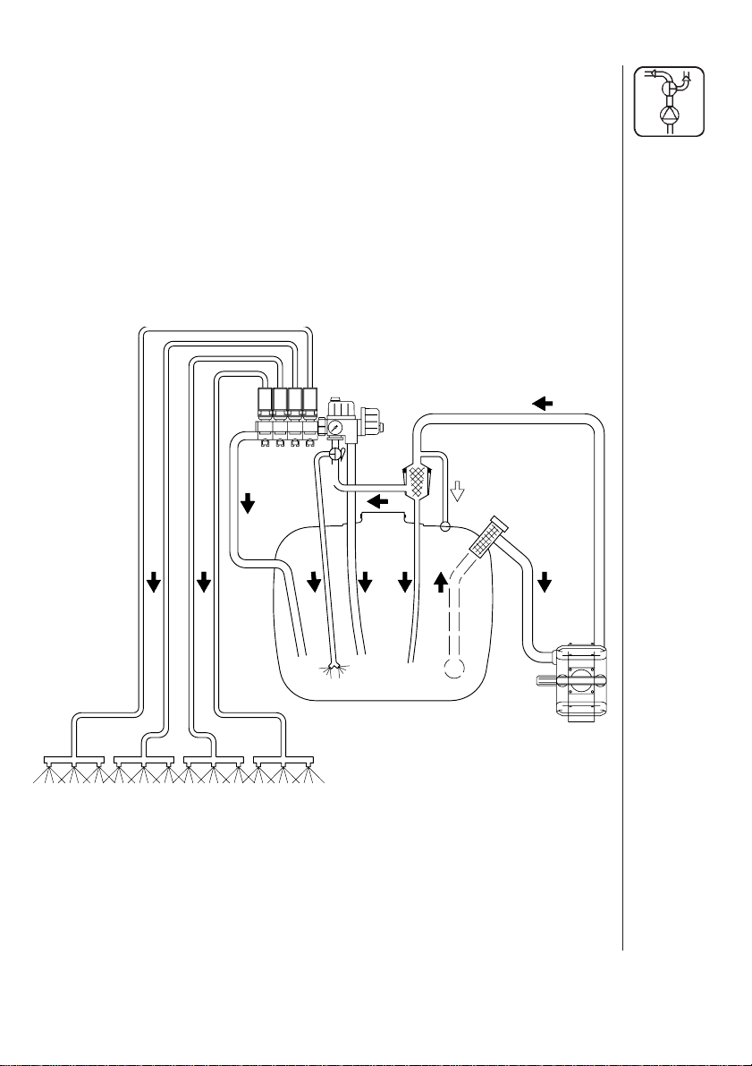
Function diagram
1. Suction filter
2. Pump
3. Self-Cleaning Filter
4. Safety valve
5. Pressure agitator
6. On/off valve with pressure gauge
7. Pressure control valve with HARDI-MATIC
8. Distribution valve with pressure equalization.
9. Sprayer boom.
8
6
7
5
3
4
1
2
9
5
Page 6
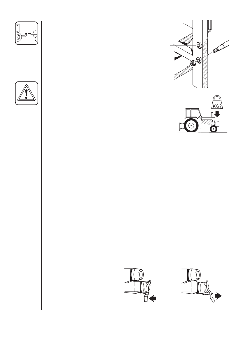
Connecting the sprayer
The sprayer is designed for three point
suspension and is equipped with 28 mm
pivots (cat. II). Pivots can be relocated to
suit the tractor.
WARNING: Note the weight of the sprayer.
Generally it is recommended to:
1. Add ballast to front of tractor.
2. Travel at slower speeds when driving
with a full tank. (The tractor braking
effect will be reduced.)
4. Be careful when filling / lifting the sprayer
for the first time.
Hydraulics
Hydraulic connection requires one double acting outlet for the D.A.H.
system. A single outlet and return can also be used. The hydraulic
hoses are marked with an arrow to indicate direction of oil flow.
The D.A.H. system requires an oil flow between 10 to 90 litres per
minute and a min. pressure of 130 bar. The system has a built-in flow
regulator that maintains constant speed on hydraulic movements.
120mm
Before operating the hydraulics, the clip at the distribution valve
(situated at front of tank) should be set for OPEN or CLOSED CENTRE tractor hydraulics.
Most tractors have OPEN CENTRE hydraulics and the valve must be
open for continuous oil circulation. For CLOSED CENTRE hydraulics
(e.g. JOHN DEERE) the clip must hold the valve closed so oil only
circulates when hydraulic movements are required.
Setting of distribution valve.
CLOSED CENTRE
6
OPEN CENTRE
Page 7
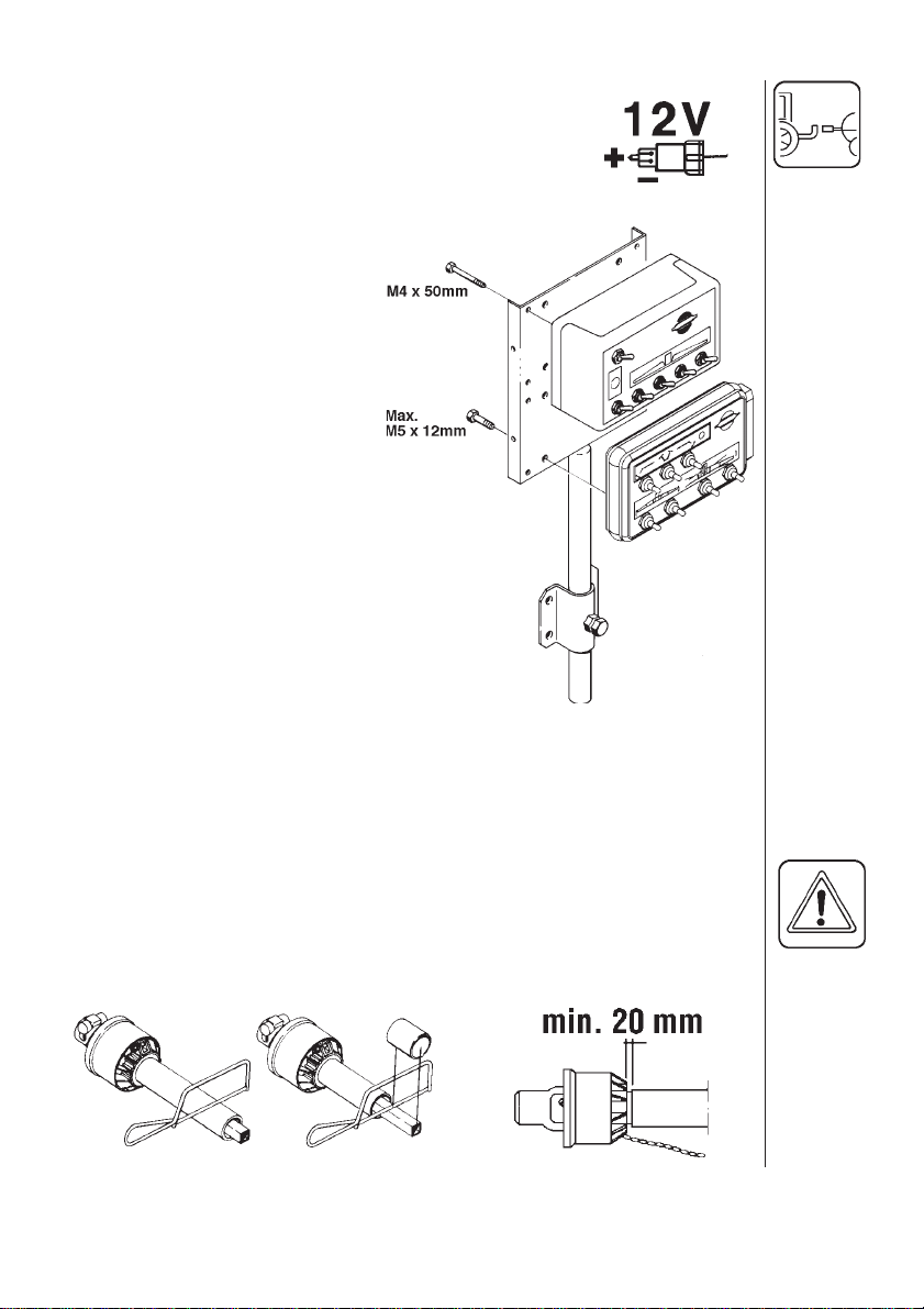
Control boxes and power supply
Power requirement is 12 V DC. Note polarity!
For EC: Brown pos. (+), Blue neg. (-).
For D.A.H.: White pos. (+), Black neg. (-).
The control boxes for ECoperating unit and for D.A.H.
are fitted in the tractor cabin at
a convenient place. See
section on Assembly for initial
mounting.
The wires must have a crosssectional area of at least 4.0
mm2 to ensure sufficient power
supply.
For the EC-operating unit the
tractor circuit should have a 8
Amp fuse and for the D.A.H. a
16 Amp fuse.
Use the HARDI Electric distribution box (No. 817925) if the
tractor has a doubtful power
supply.
Rear lights (if fitted)
Connect plug for rear lights to the tractors 7-poled socket and check
that rear lights, stop lights and turning indicators function.
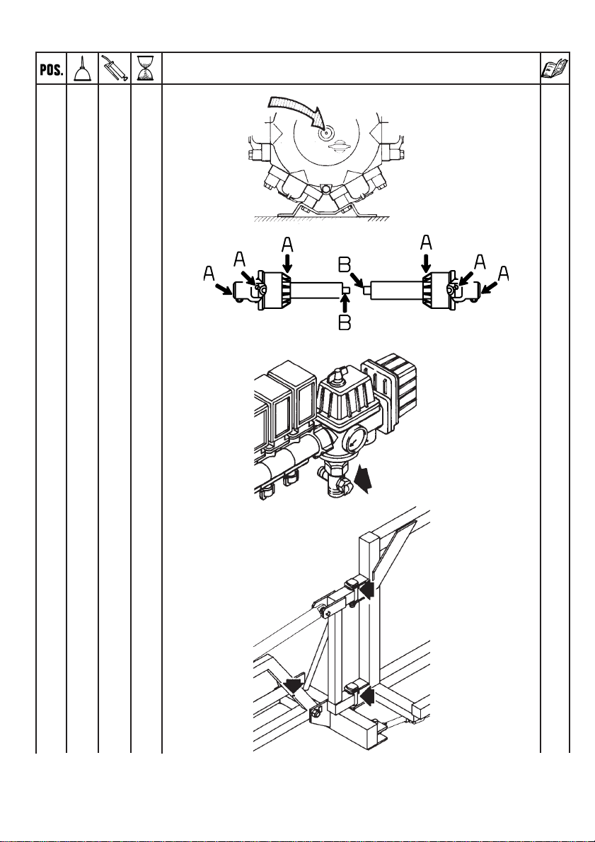
Transmission shaft
When connecting the sprayer to the tractor the length of the transmission shaft should be checked and if necessary shortened. There
should be at least 20 mm free play between the male and female parts
when the shaft is horizontal.
7
Page 8
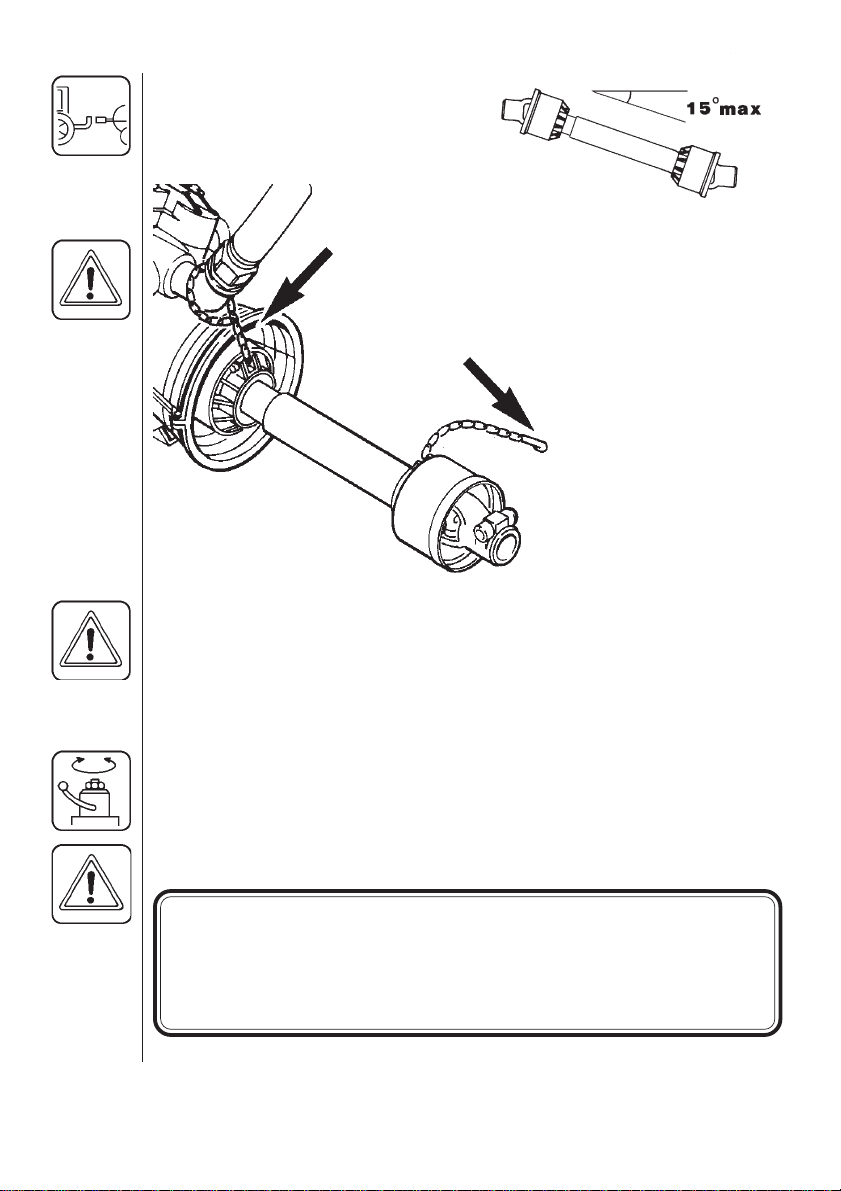
To ensure long life of the transmission shaft, try to avoid working
angles greater than 15°.
It is important for the
personal safety of the
operator that the
transmission shaft is
intact.
The protection guards
must cover the whole
shaft. This includes the
universal cross covers
at each end of the
shaft. The chains are
connected so that the
protection guards do
not rotate with the
shaft.
Roadworthyness
When driving on public roads and other areas where the highway code
applies, or areas where there are special rules and regulations for
marking and lights on implements, you should observe these and
equip implements accordingly.
Operating instructions
Operating of the boom
WARNING: BEFORE UNFOLDING THE BOOM IT IS IMPORTANT
THAT THE SPRAYER IS CONNECTED TO THE TRACTOR TO
PREVENT OVERBALANCING.
BE CAUTIOUS WITH INITIAL USE OF THE HYDRAULIC SYSTEM; IF THERE IS AIR IN THE SYSTEM THIS MAY CAUSE VIOLENT MOVEMENTS OF THE BOOM. THEREFORE TAKE CARE
THAT NO PERSONS OR OBJECTS ARE HURT OR DAMAGED
IN THE PROCESS OF TESTING.
8
Page 9
First set the tractor’s hydraulic remote
control lever in position for correct direction of oil flow.
If the boom starts to rise either switch the
hydraulic hoses around or set the control
lever in the opposite position.
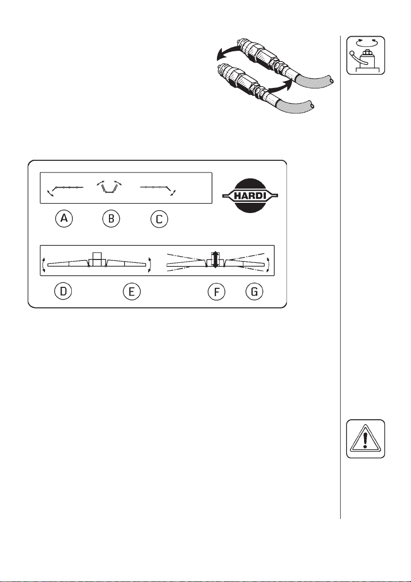
Boom manoeuvering is as follows.
A. Unfolding/folding of left outer section
B. Unfolding/folding of inner section
C. Unfolding/folding of right outer section
D. Boom tilt for left side
E. Boom tilt for right side
F. Raising and lowering of boom
G. Slanting of boom
Unfolding of boom
ENSURE THAT THE BOOMS ARE CLEAR FROM THE TRANSPORT
BRACKETS BEFORE UNFOLDING.
1. Push switch F upward to lift the boom clear of the rear transport
brackets.
2. Push switch D and E upward to ensure boom sections are clear of
the front transport brackets.
9
Page 10
3. Push switch B upward to unfold the inner sections.
4. Push switch A and C upward to unfold outer sections.
5. Push switch D and E downward to lower right and left sections.
6. Push switch F downward to lower the boom to correct height above
crop or ground level.
CAUTION
The 3 upper functions, in the red rectangle with STOP sign, must only
be operated when sprayer is stationary.
Failure to do so will damage the boom.
Folding of boom
1. Raise boom F to upper position.
2. Check the slanting function is midway G.
3. Fold outer sections, A and C.
4. Raise right and left sections D and E.
5. Fold inner sections B.
6. Lower boom F until boom rests on rear transport brackets.
7. Lower right and left boom sections until they rest the front transport
brackets D and E.
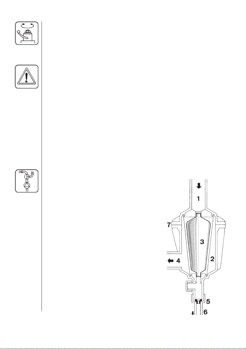
Self-Cleaning Filter
Function diagram
1. From pump
2. To safety valve (operating pressure
is 15 bar)
3. Double filter screen
4. Guide cone
5. To operating unit
6. Replaceable restrictor
7. Return to tank
8. Nut
8
10
Choice of restrictor
It is important to have a large flow through
the filter. This is achieved by choosing the
restrictor size in relation to the liquid consumption of the spray boom.
Page 11
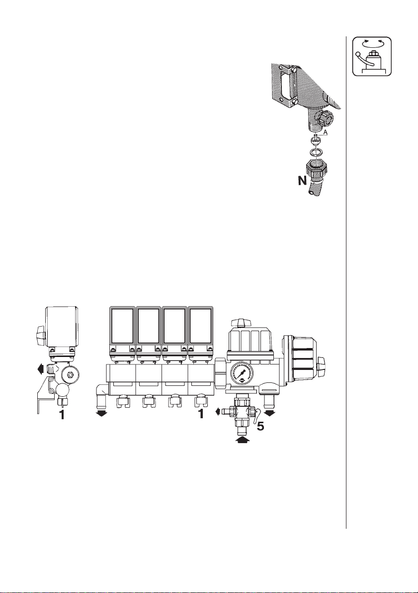
4 restrictors are supplied. Use the green one (largest orifice A) first.
The hose N is unscrewed at the Self-Cleaning Filter,
the restrictor is put in the hose and the hose is
mounted again.
If the required working pressure cannot be obtained,
the restrictor is too large. Choose a smaller
restrictor.
Start with the black one, then the white and finally
the red one.
When cleaning the filter remove hose N and the
hose at the safety valve, and check there are no
residues.
Standard filter size is 80 mesh. Sizes of 50 and 100 mesh are available
and can be changed by opening the filter top. Check the O-rings before
reassembling the filter and replace if damaged.
Adjustment of the controls
2
4
EC operating unit
1. Adjust screw for pressure equalization
2. On/off valve
3. Pressure control valve
4. Distribution valve
5. Pressure agitation valve
3
11
Page 12
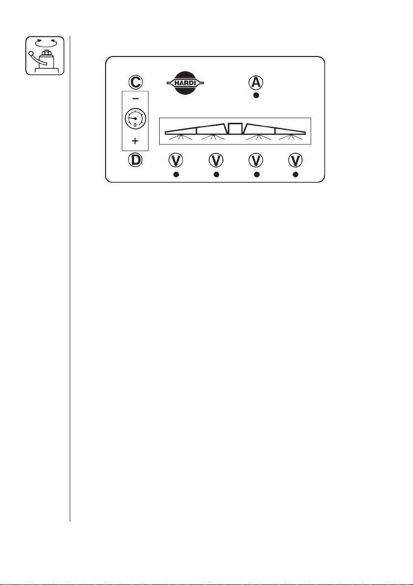
EC remote control box
A. Operating switch for on-off valve
V. Operating switch for distribution valves
C. Pressure regulation switch (to lower)
D. Pressure regulation switch (to raise)
1. Choose the correct nozzle size by turning the TRIPLET nozzle
bodies to the suitable nozzle for the spray purpose. Make sure that
all nozzles are the same type and capacity. See “Spray Technique”
book.
2. Open or close lever 5 depending on whether pressure agitation is
required. (Remember pressure agitation takes 5% to 10% of pump
output).
3. On-off switch A is activated against green.
4. All distribution valves switches V are activated against green.
5. Pressure regulation switch C is activated until emergency handle 3,
stops rotating (minimum pressure).
6. Put the tractor in neutral and adjust the P.T.O. and thereby the
number of revolutions of the pump corresponding to the intended
travelling speed.
Remember the number of revolutions on the P.T.O. must be kept
between 300-600 r/min.
7. Pressure regulation switch D is activated till the recommended
pressure is shown on the pressure gauge.
12
ADJUSTMENT OF PRESSURE EQUALIZATION:
8. Close the first distribution valve switch V.
9. Turn the adjusting screw 1 until the pressure gauge again shows
the same pressure.
Page 13
10.Adjust the other sections of the distribution valve in the same way.
NOTE: HEREAFTER ADJUSTMENT OF PRESSURE EQUALIZATION
WILL ONLY BE NEEDED IF YOU CHANGE TO NOZZLES WITH
OTHER CAPACITIES.
11.Operating the control unit while driving:
In order to close the entire boom switch on-off A to off position. This
returns the pump output to the tank through the return system. The
diaphragm anti-drip valves ensure instantaneous closing of all
nozzles.
In order to close one or more sections of the boom, switch the
relevant distribution valve V to off position. The pressure equalization ensures that the pressure does not rise in the sections which
are to remain open.
In case of power failure it is still possible to activate all functions of the
operating unit. See section “Emergency operation of the sprayer”.
When the sprayer is put aside, the control box and the multiplug must
be protected against moisture and dirt. A plastic bag may be used to
protect the multi plug.
Operation of the tank drain valve
Pull the red handle on the side of the tank to open the drain valve. The
valve is spring-loaded, but can be kept open by pulling the string out
and upwards in the V-shaped slit. To release, pull the string downwards and the valve will close automatically.
13
Page 14
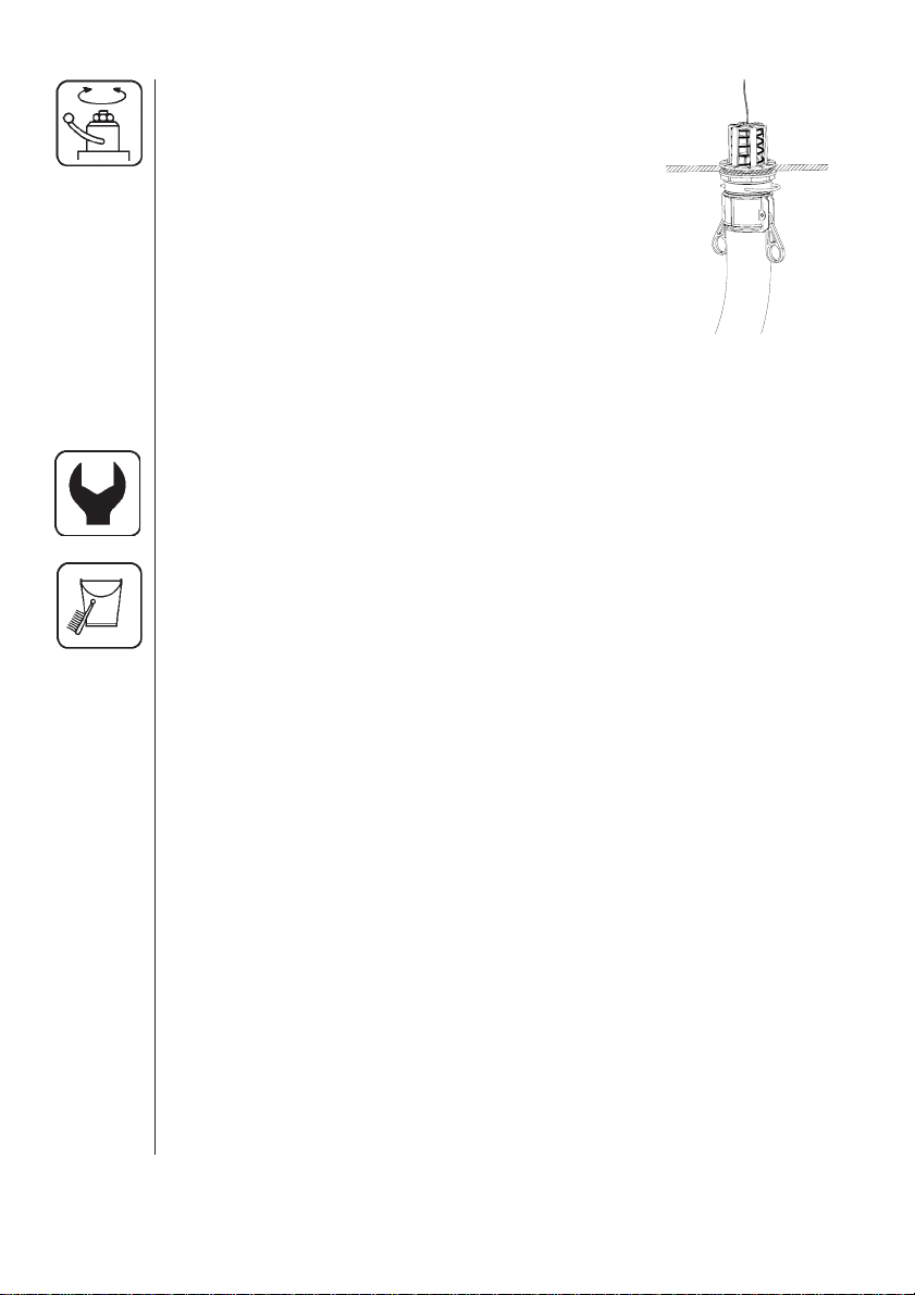
If draining residues, e.g. liquid fertilizer into a
reservoir, a snap-coupler with hose can rapidly
be connected to the drain valve and the liquid
safely drained.
Spray Technique - see separate book.
Optional Extras - see separate books.
Maintenance
In order to derive full benefit from the sprayer for many years the
following few but important rules should be kept:
Cleaning the sprayer
Guidelines
Read the whole label of the chemical. Take note of any particular
instructions regarding recommended protective clothing, deactivating
agents, etc. Read the detergent and deactivating agent labels. If
cleaning procedures are given, follow them closely.
14
Be familiar with local legislation regarding disposal of pesticides
washings, mandatory decontamination methods, etc. Contact the
appropriate body, eg. Dept of Agriculture.
Pesticide washings can usually be sprayed out on a soakaway. This is
an area of ground that is not used for cropping. You must avoid seepage or run-off of residues into streams, water courses, ditches, wells,
springs, etc. The washings from the cleaning area must not enter
sewers. Drainage must lead to a soakaway.
Cleaning starts with the calibration, as a well calibrated sprayer will
ensure the minimal amount of remaining spray liquid.
It is good practice to clean the sprayer immediately after use thereby
rendering the sprayer safe and ready for the next pesticide application.
This also prolongs the life of the components.
Page 15

It is sometimes necessary to leave spray liquid in the tank for short
periods, eg. overnight, or until the weather becomes suitable for
spraying again. Unauthorized persons and animals must not have
access to the sprayer under these circumstances.
If the product applied is corrosive, it is recommended to coat all metal
parts of the sprayer before and after use with a suitable rust inhibitor.
Remember: Clean sprayers are safe sprayers.
Clean sprayers are ready for action.
Clean sprayers can not be damaged by pesticides and
their solvents.
Cleaning
1. Dilute remaining spray liquid in the tank with at least 10 parts water
and spray the liquid out in the field you have just sprayed.
NOTE: It is advisable to increase the forward speed (double if possi-
ble) and reduce the pressure.
For 4110 nozzles: 1.5 bar minimum
For 1553 nozzles: 3.0 bar minimum
2. Select and use the appropriate protective clothing. Select detergent
suitable for cleaning and suitable deactivating agents if necessary.
3. Rinse and clean sprayer and tractor externally. Use detergent if
necessary.
4. Remove tank and suction filters and clean. Be careful not to damage
the mesh. Replace cap for suction filter. Replace filters when the
sprayer is completely clean.
5. With the pump running, rinse the inside of the tank. Remember the
tank roof. Rinse and operate all components and any equipment that
has been in contact with the chemical.
Before opening the distribution valves and spraying the liquid out,
decide whether this should be done in the field again or on the
soakaway.
6. After spraying the liquid out, stop the pump and fill at least 1/5 of the
tank with clean water. Note that some chemicals require the tank to be
completely filled. Add appropriate detergent and/or deactivating agent,
eg. Washing soda or Triple ammonia.
15
Page 16

NOTE: If a cleaning procedure is given on the chemical label, follow it
closely.
7. Start the pump and operate all controls enabling the liquid to come
in contact with all the components. Leave the distribution valves until
last. Some detergents and deactivating agents work best if left in the
tank for a short period. Check the label.
The Self-Cleaning Filter can be flushed by removing the bypass hose
from the bottom of the filter. Stop the pump and remove the hose. Start
the pump for a few seconds to flush filter. Be careful not to loose the
restrictor nozzle.
8. Drain the tank and let pump run dry. Rinse inside of tank, again
letting the pump run dry.
9. Stop the pump. If the pesticides used have a tendency to block
nozzles and filters, remove and clean them now. Check also for
sediment on the pressure side of the safety valve for the Self-Cleaning
Filter.
10. Replace all the filters and nozzles and store the sprayer. If, from
previous experiences, it is noted that the solvents in the pesticide are
particularly aggressive, store the sprayer with the tank lid open.
16
NOTE: If the sprayer is cleaned with a high pressure cleaner we
recommend lubrication of the entire machine.
Filters
Clean filters ensure;
• Sprayer components such as valves, diaphragms and operating unit
are not hindered or damaged during operation.
• Nozzle blockages do not occur whilst spraying.
• Long life of pump. A blocked suction filter will result in pump cavitation.
Page 17
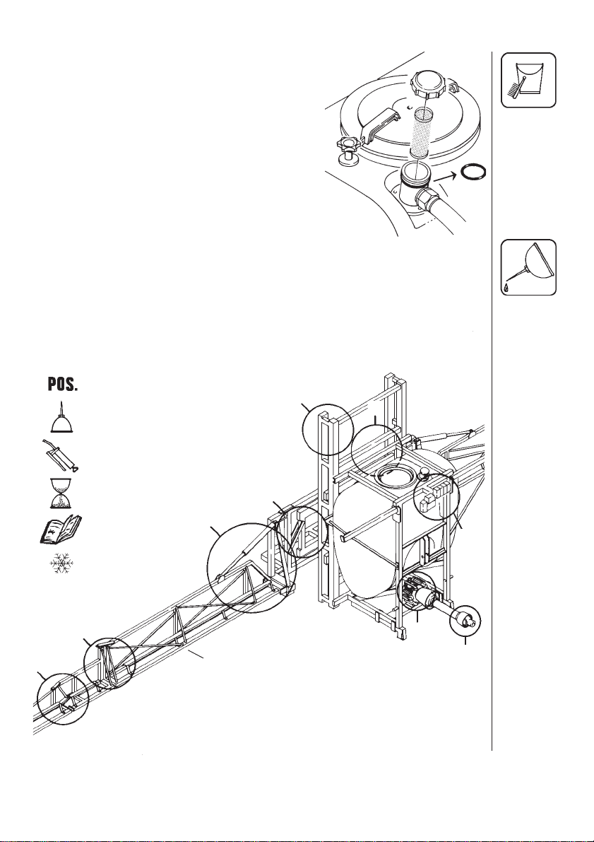
The main filter protecting sprayer components is the suction filter at the top of the
tank. Check it regularly.
Ensure the O-ring on filter housing is in
good condition and lubricated.
Lubrication
Recommended lubrication is shown in following tables.
Use ball bearing grease (lithium grease No.2).
NOTE: If the sprayer is cleaned with a high pressure cleaner or corrosive products have been sprayed out, we recommend lubrication of
all sections.
Position of the sprayer
6
Oil
Grease
6
Hours
See further details
on page:
Winter storage
4
7
8
9
5
3
1
2
17
Page 18
1x40
26
2A x 12
Bx40
3x 20
4x 40
7
8
7
11
12
27
33
22
23
18
Page 19

5x40
21
6x40
19
Page 20

7
Ax 40
Bx40
8x 20
23
9x 40
20
Page 21

Re-adjustment of the Boom
After having used the sprayer for some days the boom should be
adjusted according to the following instructions.
NOTE:Tractor and sprayer must be on level ground.
Sprayer must be lubricated. (see section “Lubrication”).
WARNING
NOBODY MUST STAND UNDER THE BOOM WHILST ADJUSTMENT IS TAKING PLACE.
Boom lift
The boom lift should
be adjusted so the
boom can freely
move up and down
when the lift ram is
actuated.
1. Unfold the boom.
2. Loosen counter
nuts K and adjust
the screws J so the
glide pads are just
touching at all
points in both
directions. Tighten
counter nuts.
K
J
M
K
M
J
N
K
J
N
K
J
M
Trapeze suspension
For the trapeze to function it must not be overtight. If it is to loose the
boom will yawn (forward and back movement). This results in a poor
spray distribution.
1. With the boom unfolded, check the tension on nuts M. They must
not be overtight.
2. The trapeze function is adjusted by tightening or loosening the 4
nuts N.
Minor adjustment in the field may be necessary.
21
Page 22

Transport position
The boom and transport brackets are to be adjusted so that boom
movement is prevented when in transport.
1. Fold the outer sections and then the inner sections until the folding
rams are at minimum length and carefully place the boom in the
transport brackets.
NOTE: The following is best done without pressure in the hydraulic
rams.
2. Loosen counter nut C and adjust the length of the rod F until the
boom rests against G at the transport bracket.
22
G
3. Now move the boom stop H on
the transport bracket up to the
boom. Tighten counter nuts.
H
Page 23

Linear adjustment of outer sections
NOTE: The following is
best done without pressure in the hydraulic
rams.
1. Unfold the boom.
2. Loosen counter nut O
and adjust the length of
the rod until the outer
and inner sections are
parallel. Tighten counter nut.
Linear adjustment of inner sections (12 to 21 m)
NOTE: The following is best done without pressure in the hydraulic
rams.
1. Unfold the boom.
2. Loosen counter nut B. Adjust the threaded bushing D until the boom
is at right angle to the tank frame. Tighten counter nut.
O
B
D
23
Page 24

Adjustment of inner and intermediate sections (24 m)
1. Unfold the boom.
2. Check that the ram rod is fully withdrawn. Adjust rigging screw if not so.
3. Midway on the wire of the inner section, check the tension. A 10 kg
force the wire should move a maximum of 3 mm. Adjust rigging
screw if necessary.
4. Midway on the wire of the intermediate section, check the tension.
A 10 kg force the wire should move a maximum of 10 mm. Adjust
rigging screw if necessary.
5. Fold the boom.
24
Page 25

6. Midway on the wire of the inner section, check the tension. A 10 kg
force the wire should move a maximum of 3 mm. Adjust rigging
screw if necessary.
7. Midway on the wire of the intermediate section, check the tension. A
10 kg force the wire should move a maximum of 20 mm. Adjust
rigging screw if necessary.
REMEMBER TO TIGHTEN ALL COUNTER NUTS AFTER
ADJUSTMENT.
25
Page 26

Changing of valves and diaphragms
Valves
Remove valve cover
1. Before changing
the valves 2 note the
orientation of the
valves so that they
are replaced correctly.
Important: Note
valve with white flap
2A is placed in the
valve opening
shown.
It is recommended to
use new O-rings 3
when changing or
checking the valves.
Diaphragms
Remove the diaphragm bolt 4 after having dismantled the valve cover
as indicated above.
The diaphragm 5 may then be changed. If fluids have reached the
crankcase, re-grease the pump thoroughly.
Reassemble with the following torque settings:
26
Pump Valve cover Diaphragm
Model Nm bolt Nm
361 70 60
1 Nm = 0.74 ft-lb
Level indicator
Depending on products used, it can become difficult
to see the red sphere inside the level indicator tube.
Note that the tube can be replaced when necessary.
Page 27

Changing of ball seat in operating unit
If problems with on/off valve occurs (e.g. dripping nozzles when on/off
valve is closed), the ball and ball seat should be checked.
Remove the 2 bolts
fixing the on/offpressure valve unit
to the bracket,
unscrew the union
nut A and pull the
on/off-pressure
valve away from the
distribution valves.
Check the ball for sharp edges and scratches and check the ball seat
for cracks and wear - replace if necessary.
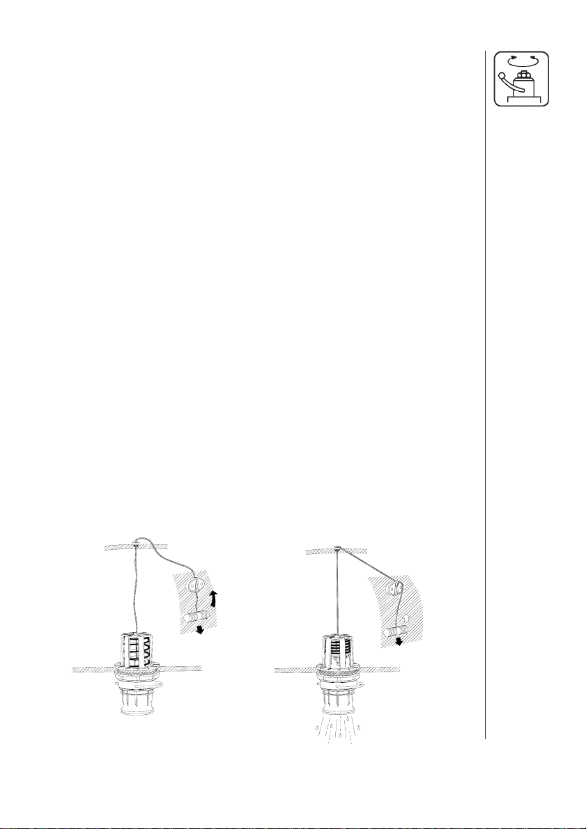
Check of valve cone in distribution valves
Periodically check the distribution valves for proper sealing.
Run the sprayer with clean water and
open on/off and all distribution valves.
Cautiously remove clip A and hose B for
the pressure equalization device. When
the housing is drained, there should be
no liquid flow through the pressure
equalization device. If there is any
leakage, the valve cone E must be
changed.
Remove the clip C, and lift the EC motor
off the valve housing. Then unscrew the
screw D and replace the valve cone E.
Reassemble in opposite sequence.
27
Page 28

Nozzle tubes and fittings
Poor seals are usually caused by;
• missing O-rings or gaskets
• damaged or incorrectly seated O-rings
• dry or deformed O-rings or gaskets
• foreign bodies
Therefore, in case of leaks: DO NOT overtighten. Disassemble, check
condition and position of O-ring or gasket, clean lubricate and reassemble.
For radial connections only hand tighten them.
The O-ring to be lubricated ALL THE WAY ROUND before fitting on to
the nozzle tube.
For axial connections, a little
mechanical leverage may be
used.
28
Off-season storage
When the spraying season is over you should devote some extra time
to the sprayer before it is stored.
Hoses
Check that none of the hoses are caught or have sharp bends.
A leaky hose can give an annoying delay in the middle of the spraying
job. Therefore check all the hoses and change if there is any doubt
about the durability.
Paint
Some chemicals are very hard on paints. It is therefore well advised to
remove rust, if any, and then touch up the paint.
Page 29

Tank
Check that no chemical residues are left from the last spraying. Chemical residues must not be left in the tank for a long time. It will reduce
the life of the tank. See section on Cleaning the sprayer.
Operating unit
When the sprayer is put away the control box and the multiplug must
be protected against moisture and dirt. Possibly use a plastic bag.
Transmission shaft
Check that the transmission shaft fulfills its security purpose, e.g. that
shields and protective tubes are intact.
Anti-freeze precaution
If the sprayer is not stored in a frost-proof place you should take the
following precautions: Put at least 10 litres of 33% anti-freeze mixture
in the tank and let the pump run a few minutes so that the entire
system including spray hose are filled. Remove the glycerine filled
pressure gauge and store it frost free in vertical position.
The anti-freeze solution also hinders the O-rings and gaskets from
drying out.
Operational problems
In cases where breakdowns have occurred the same factors always
seem to come into play:
● Minor leaks on the suction side of the pump will reduce the pump
capacity or stop the suction completely.
● A clogged suction filter will hinder or prevent suction so that the
pump does not operate satisfactorily.
● Clogged up pressure filters will result in increasing pressure at the
pressure gauge but lower pressure at the nozzles.
● Foreign bodies stuck in the pump valves with the result that these
cannot close tightly against the valve seat. This reduces pump
efficiency.
● Poorly reassembled pumps, especially diaphragm covers will allow
the pump to suck air resulting in reduced or no capacity.
● Electrical and hydraulic components that are contaminated with dirt
result in poor connections and rapid wear to the hydraulic system.
29
Page 30

Therefore ALWAYS check:
1. Suction, Self-Cleaning, pressure and nozzle filters are clean.
2. Hoses for leaks and cracks, paying particular attention to
suction hoses.
3. Gaskets and O-rings are present and in good condition.
4. Pressure gauge is in good working order. Correct dosage depends on it.
5. Operating unit functions properly. Use clean water to check.
6. Electrical and hydraulic components are maintained clean.
Fault Probable cause Control / remedy
Liquid system
No spray from
boom when
turned on.
Air leak on suction.
Check if red suction lid/O-ring are
sealing.
Check suction tube and fittings.
Check tightness of pump diaphragm
and valve covers.
Lack of
pressure.
Pressure
dropping.
Air in system.
Suction/pressure
filters clogged.
Incorrect assembly.
Pump valves blocked
or worn.
Defect pressure
gauge.
Filters clogging.
Fill suction hose with water for initial
prime.
Clean filters.
Check yellow suction pipe is not
obstructed or placed too near the
tank bottom.
Agitation nozzles not fitted.
Restrictor nozzle in Self-Cleaning
Filter not fitted.
Safety valve spring for Self-Clean-
ing Filter not tight.
Too little distance between yellow
suction pipe and tank bottom.
Check for obstructions and wear.
Check for dirt at inlet of gauge.
Clean all filters. Fill with cleaner
water.
If using powders, make sure
agitation is on.
30
Page 31

Pressure
dropping.
Nozzles worn.
Check flow rate and replace nozzles
if it exceeds 10%.
Pressure
increasing
Formation of
foam.
Liquid leaks
from bottom of
pump.
Operating unit
EC operating
unit not functioning .
Tank is airtight.
Sucking air towards
end of tank load.
Pressure filters
beginning to clog.
Agitation nozzles
clogged.
Air is being sucked
into system.
Excessive liquid
agitation.
Damaged diaphragm.
Blown fuse(s).
Check vent is clear.
Excessive agitation, turn off.
Returns inside tank need relocation.
Clean all filters.
Check by turning agitation off/on.
Check tightness / gaskets / O-rings
of all fittings on suction side.
Turn agitation off.
Reduce pump r/min.
Check safety valve for Self-Cleaning
Filter is tight.
Ensure returns inside tank are
present.
Use foam damping additive.
Replace. See Changing of valves
and diaphragms.
Check mechanical function of
microswitches. Use cleaning/
lubricating agent if the switch does
not operate freely.
Wrong polarity.
Valves not closing
properly.
No power.
Check motor. 450-500 milli-Amperes
max. Change motor, if over.
Brown - pos. (+). Blue - neg. (-).
Check valve seals for obstructions.
Check microswitch plate position.
Loosen screws holding plate
1
a
/2 turn.
Wrong polarity. Check that brown is
pos. (+), Blue is neg. (-).
Check print plate for dry solders or
loose connections.
Check fuse holders are tight around
fuse.
31
Page 32

Fault Probable cause Control / remedy
Hydraulic system
Hydraulic
movements of
boom are fast/
slow/erratic.
Air in system.
Insufficient hydraulic
pressure.
Loosen ram connections and
activate hydraulics until oil flow has
no air in it (not whitish).
Check output pressure of tractor
hydraulics. Minimum for sprayer is
130 bar.
Particular ram
not functioning.
Insufficient amount of
oil in tractor reservoir.
Restrictor blocked.
Check and top up if needed.
Place boom in transport bracket.
Dismantle and clean
Emergency operation of the sprayer
The boom
In case of power failure the boom can be
operated manually by pressing the
individual buttons on the solenoid valves.
This is done by locking the distribution
valve, as is done when using tractors
with closed centre hydraulics.
Remove the protection box of the solenoid valves at the boom. The boom can now be operated by pressing
the individual buttons on the solenoid valves.
Remember to reset the
system to open centre
hydraulic, if the tractor
has an open centre
hydraulic system.
The problem may be due
to a blown fuse. One
spare fuse is located
inside the junction box.
32
Fuse type T 10 A 250 V
HARDI ref. no. 261272
Page 33

EC operating unit
In case of power failure it is possible to operate all functions of the
operating unit manually. First
disconnect the multiplug from the
control box. Now manually turn the
emergency control knobs.
The problem may be due to a
blown fuse. The fuses are placed in
the control box and are marked
according to functions. Fuses 7 and
8 are spare fuses.
Fuse type T 500 mA
HARDI ref. no. 261125
Technical specifications
Measure and weight
Tank Spraying Measure Weight
size width a × b × ckg
lm cm
12 310 × 255 × 300 753
15 410 × 255 × 330 782
16 410 × 255 × 330 797
800 18 430 × 255 × 350 867
20 450 × 255 × 370 891
21 450 × 255 × 370 917
24 420 × 255 × 345 1010
12 310 × 255 × 300 783
15 410 × 255 × 330 812
16 410 × 255 × 330 827
1000 18 430 × 255 × 350 897
20 450 × 255 × 370 921
21 450 × 255 × 370 947
24 420 × 255 × 345 1040
12 310 × 255 × 300 833
15 410 × 255 × 330 862
16 410 × 255 × 330 877
1200 18 430 × 255 × 350 947
20 450 × 255 × 370 971
21 450 × 255 × 370 997
24 420 × 255 × 345 1090
a
c
b
33
Page 34

Power consumption and capacity
361/9.5
bar l/min kW l/min kW l/min kW l/min kW l/min kW
0 95 0,92 127 1,33 158 1,56 171 1,69 189 1,85
5 92 1,49 123 1,93 151 2,38 165 2,63 183 2,98
10 91 2,22 120 2,89 148 3,69 163 4,02 180 4,74
15 89 3,03 119 3,92 148 4,90 160 5,40 177 6,15
Rotation per min. r/min Capacity l/min Suction height 0,0 m
Power consumption kW Max. pressure 15 bar Weight 54, 0 kg
300 400 500 540 600
r/min
Filters and nozzles
Pos. Mesh/ Description
colour
1. 30 suction filter
2. 80 Self-Cleaning Filter
3. 50 blue S 4110-14 orange
4. 50 blue S 4110-16 red
5. 50 blue S 4110-20 green
34
2
1
3-4-5
Page 35

Electric and hydraulic diagram
Boom raise/lower
35
Page 36

Electric and hydraulic diagram
Distribution box
36
Page 37

Electric and hydraulic diagram
hydraulic system
37
Page 38

Pictorial symbols
EC Declaration of Conformity
Description
Function
Connection
Warning
Operation
Service/adjustment
Liquid flow
38
Pressure
Cleaning
Lubrication
Winter / off-season storage
Operational problems
Technical specifications
Page 39

Assembly
Preassembly information
The sprayer is supplied ex-works in shipping packages (SP). Number
of SP’s per sprayer varies depending on model. As this covers all LZ
models, please note the fittings covering exactly your model.
NOTE:
Removal of the plastic bag covering the tank is easiest done before
assembly.
Some components are shipped within the tank. Check inside.
Packaging information
Materials used for packaging are environmentally compatible. They
can be safely deposited or they can be burnt in an incinerator.
Recycling
Cardboard: Can recycle up to 99% and therefore should be put into
the waste collection system.
Polystyrene foam: Can be recycled. Fluorocarbons (CFC) not used in
foam production.
Polyethylene: Can be recycled.
Materials
Tank HDPE
Pressure hose PVC
Suction hose PVC
When the equipment has completed its working life, it must be thoroughly cleaned. The tank, hose and synthetic fittings can be incinerated. The metallic parts can be scrapped.
39
Page 40

40
1. Mount the boxes on the holder delivered or a suitable bracket for the
purpose.
WARNING: The screws for mounting the D.A.H. control box must not
be too long (max. 12 mm) as they may cause a short circuit!
2. Mount the boom wings. A crane or forklift will be needed. It will help
to fully extend the tilt rams so the boom wings do not have to be
raised as much.
WARNING: Remember to secure the sprayer from over-balancing.
Page 41

A
3. Nozzle tubes are supplied with one lock nozzle saddle per tube A.
The rest can slide lengthwise B allowing for extension and contraction.
4. Tubes and hoses are connected.
Fit tubes using synthetic nut.
Press down 1, turn 2.
Do not over-tighten.
Fit filter and COLOR TIPS.
Lubricate O-rings with non-mineral
oil to aid assembly.
B
41
Page 42

12 m LHZ
15 m LHZ
16 m LHZ
18 m LHZ
20 m LHZ
21 m LHZ
24 m LHZ
42
Page 43

5. Secure feed and connecting hoses with plastic straps (approx. every
30 cm). Check that the hoses do not catch or pinch during folding
and unfolding.
43
Page 44

44
A13
Page 45

B104
45
Page 46

B105
Page 47

B205
Page 48

48
C208
Page 49

C209
49
Page 50

50
D203
Page 51

D300
51
Page 52

52
D301
Page 53

D302
53
Page 54

54
D303
Page 55

D304
55
Page 56

56
D904
Page 57

E11
57
Page 58

58
E109
Page 59

K604
HELGESHØJ ALLÉ 38 • DK 2630 TAASTRUP • DENMARK
HARDI INTERNATIONAL A/
0396
EN 1152 / ISO 5674
POS.
AX 8
BX 40
rpm kW Nm
540 12 210
1000 18 172
S
HARDI
978389
59
Page 60

Notes:
60
 Loading...