

Page 1

Contents
Description .................................................................2
Operation diagram ..................................................... 4
Connecting the sprayer .............................................. 5
Operating instructions ................................................7
Operation of the MB boom....................................7
Operation of the HB boom .................................... 8
Operation of trapeze ............................................. 9
Adjustment of the operating unit ......................... 10
Drain valve operation ..........................................11
Maintenance.............................................................12
Lubrication ..........................................................12
Re-adjustment of the boom................................. 18
Changing of valves and diaphragms................... 20
Changing of ball seat in operating unit................ 22
Off-season storage .............................................23
Operational problems............................................... 24
Technical specifications ...........................................27
Pictorial symbols ......................................................29
Spare parts...............................................................30
LX -
MB/HB
Instruction book
673514-GB-92/03
HARDI INTERNATIONAL A/S reserve the right to make changes in design or to add new features without any
obligation in relation to implements purchased before or after such changes.
1
Page 2
We congratulate you for choosing a HARDI plant protection product. The reliability and efficiency of this product depend on your care.
The first step is to carefully read and pay attention to this instruction
book. It contains essential information for the efficient use and long life
of this quality product.
As the instruction book covers all LX models, please pay attention to
the paragraphs dealing with precisely your model. This book is to be
read in conjunction with the Spray Technique book.
Description
The Hardi LX models consist of a pump, frame with tank of 600, 800,
1000 or 1200 litre capacity, BK operating unit, 10, 12, 15, 16 or 18
metre trapeze suspended booms and transmission shaft.
The design of the diaphragm pump is simple, with easily accessible
diaphragms and valves that ensures liquid does not come in contact
with the vital parts of the pump.
The tank, made of impact-proof and chemical resistant polyethylene,
has a purposeful design with no sharp edges for easy cleaning and
efficient agitation. A suction filter is located at the top of the tank. This
facilitates filter inspection even if the tank is filled with spray liquid. To
ensure safe operation, the drain valve is also located at the top of the
tank.
The BK 180 K operating unit consists of; pressure agitator, safety
valve, on/off function, pressure filter with pressure gauge, distribution
valves with pressure equalization device and HARDI-MATIC.
HARDI-MATIC ensures a constant volume per hectare of the liquid at
varying speed in the same gear. The number of revolutions on the
P.T.O. must be kept between 300-600 r/min.
2
Page 3

LX-MB
LX-HB
The MB spray boom (10 or 12 metre) or the HB spray boom (12, 15,
16 or 18 metre) is fitted. The boom is supported by a trapeze which
protects the boom against vibrations and shocks when driving on
uneven ground. This ensures longer boom life and improves boom
stability for an optimal spray pattern. Height adjustment of the boom is
hydraulic. The boom is fitted with spring loaded breakaways at the
pivots.
Identification plate
An identification plate fitted on the frame indicates model, year of
production and serial number, and country of origin.
3
Page 4
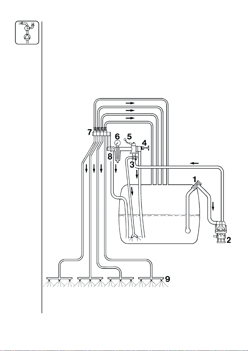
Operation diagram
1. Suction filter
2. Pump
3. Pressure agitator valve
4. Safety valve
5. On/off valve
6. Pressure filter with pressure
gauge
7. Distribution valve with pressure
equalization
MB boom - 3 sections
HB boom - 4 sections
8. HARDI-MATIC
9. Sprayer boom
4
Page 5

Connecting the sprayer
The sprayer is designed for three point
suspension and is equipped with 28
mm pivots (category II). On 600 litre
model, 22 mm (category I) pivots are
fitted.
On models 800, 1000 and 1200 l the
pivot position can be altered 120 mm.
For HB boom - For increased stability
when the sprayer is detached, retractable supports are located under the
frame. Extend before detaching.
Retract after attached.
WARNING: Note the weight of the sprayer.
See section on Technical specifications.
Generally it is recommended to:
1. Add ballast to front of tractor.
2. Increase tyre pressure (see tractor
instruction book).
3. Travel at slower speeds when driving with
a full tank.
(The tractor will have decreased braking
efficiency.)
4. Be careful when filling/lifting the sprayer the first time.
120mm
HB
When connecting the sprayer to the tractor the length of the transmission shaft should be checked and if necessary shortened. There
should be at least 10 mm free play between the male and female parts
when the shaft is horizontal.
5
Page 6
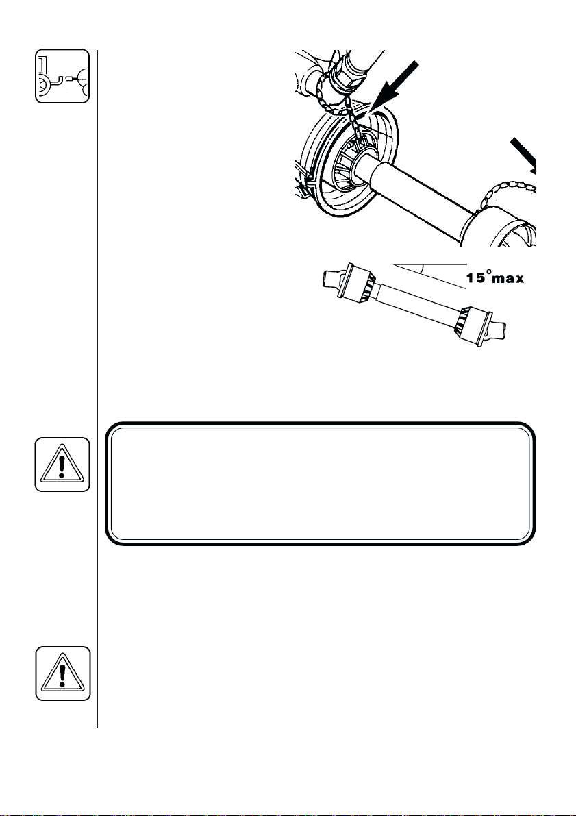
It is important for the personal
safety of the operator that the
transmission shaft is intact.
The protection guards must
cover the whole shaft. This
includes the universal cross
covers at each end of the
shaft. The chains are connected so that the protection
guards do not rotate with the
shaft.
To ensure long life of the
transmission shaft, try to avoid
working angles greater than 15°.
Hydraulics
Hydraulic connection necessitates one single acting outlet. The system
will require a capacity of approx. 2 litres and a minimum pressure of
100 bar.
WARNING
INITIAL RAISING AND LOWERING SHOULD BE DONE CAUTIOUSLY; THERE MAY BE A LITTLE AIR IN THE SYSTEM
AND THIS MAY CAUSE ERRATIC MOVEMENTS. THEREFORE TAKE CARE THAT NO PERSONS OR OBJECTS ARE
HURT OR DAMAGED IN THE PROCESS OF TESTING.
Rear lights (if fitted)
Connect plug for rear lights to the tractors 7-poled socket and check
that rear lights, stop lights and turning indicators work properly before
driving anywhere.
Roadworthyness
When driving on public roads and other areas where the highway code
applies, or areas where there are special rules and regulations for
marking and lights on implements, you should observe these and
equip implements accordingly.
6
Page 7
Operating instructions
Operation of the MB boom
Remove boom transport lock pins
A. When unfolding (or folding) the
initial force to release the spring
loaded breakaways will be higher
than the actual unfolding/folding.
CAUTION: The breakaways must
be correctly tensioned and lubricated. (see section on Re-adjustment of the boom).
A
MB
When unfolding outer sections,
ensure the outer boom locks click
into place.
Reverse procedure to fold.
7
Page 8

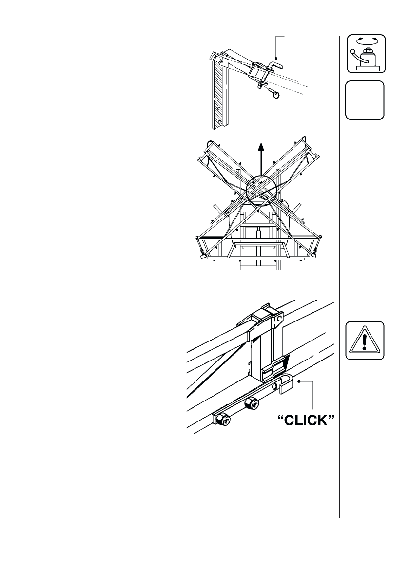
Operation of the HB boom
HB
*
➀ Remove the transport safety wire (
part. Fold arm down to tighten wire.
➁ Lift spring-loaded lock.
➂ Turn the lock 90°.
√ Lock the intermediate and central parts.
➄ Unfold outer section. Fold arm down to
tighten wire.
≈ For 16 and 18 metre unfold
breakaway ensuring the locks
click into place.
) and unfold the intermediate
*
CAUTION: The breakaways must be correctly tensioned and lubricated. (see section on Re-adjustment of the boom)
To fold the order is A - B - C - D - E - F. Remember to reattach safety
wire at transport bracket around boom.
8
Page 9
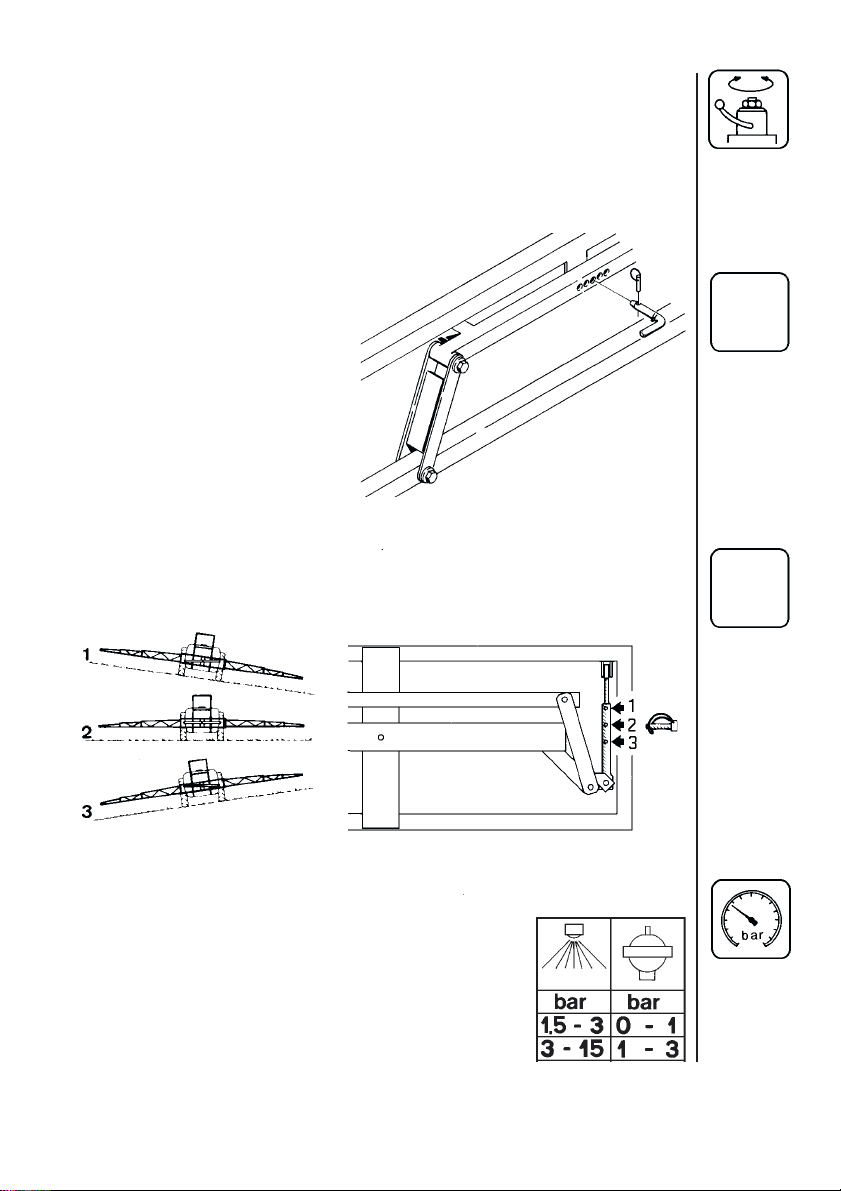
Operation of trapeze
The trapeze suspension must be correctly adjusted and regularly
lubricated, if it is going to operate satisfactorily.
The primary function of the suspension is to protect the boom against
vibrations and shocks. It also helps maintain it a uniform height above
the target.
For MB boom - Under normal
field operation, remove trapeze
lock pin C. Replace pin to block
function, for example before
folding the boom or when
spraying on sloping terrain.
For HB boom - Under normal conditions the trapeze is always active.
When spraying on flat fields, use pos. 2. On sloping terrain the boom
can be slanted (pos. 1 or 3) and still maintain an active trapeze.
C
MB
HB
Pulsation damper (if fitted)
The air pressure in the pulsation damper is preset
at the factory to 2 bar. This covers spray working
pressures between 3 and 15 bar. When using
spray pressures outside this range, the air pressure
should be adjusted as shown in the diagram. The
diagram is also embossed on the damper.
9
Page 10

Adjustment of the operating unit
10
1. Open or close lever 4 depending on whether pressure agitation is
required. (Remember pressure agitation takes 5% to 10% of pump
output).
2. Turn main on/off handle 2 to spraying position A.
3. Set all hand levers 3 on the distribution valve to spraying position A.
4. Turn the HARDI-MATIC valve 6 anti-clockwise to its extreme position.
5. Turn the safety valve 1 clockwise to maximum pressure.
6. Put the tractor in neutral and set the engine revolutions and thereby
the number of revolutions of the pump corresponding to the intended
travelling speed. Remember the number of revolutions on the P.T.O.
must be kept between 300-600 r/min.
Page 11

Adjust the HARDI-MATIC valve 6 so that the pressure gauge indicates
the recommended pressure.
ADJUST THE PRESSURE EQUALIZATION SECTIONS AS FOLLOWS:
7. Note the pressure and place the first lever 3 on the distribution valve
in position B (off position).
8. Turn the corresponding adjust screw 5 until the pressure gauge
again shows the same pressure (turn the screw clockwise for higher
pressure, anti-clockwise for lower pressure).
9. Adjust the other sections of the distribution valve in the same way.
NB: HEREAFTER ADJUSTMENT OF PRESSURE EQUALIZATION
WILL ONLY BE NEEDED IF YOU CHANGE TO NOZZLES WITH
OTHER CAPACITIES.
10. Operating the control unit while driving:
To close the entire boom, turn the handle 2 to position B. This takes
the pressure off the pump. The liquid will then return to the tank via the
return system. The diaphragm anti-drip valves ensure instantaneous
closing of all nozzles. In order to close part of the boom, move lever 3
of the distribution valve to position B (off position) for the section or
sections to be closed. The pressure equalization device ensures that
the pressure does not rise in the sections which are to remain open.
Drain valve operation
Pressure filter
The operating unit has an in-built pressure filter. It is not necessary to
dismantle the filter to clean it. When cleaning the sprayer (clean water
circulating in the tank), open the drain valve to flush the filter;
To open : A
To close : B
Tank drain
To open : A
To close : B
11
Page 12
Maintenance
In order to derive full benefit from the sprayer for many years the
following few but important rules should be kept:
Cleaning the sprayer - see Spray Technique book.
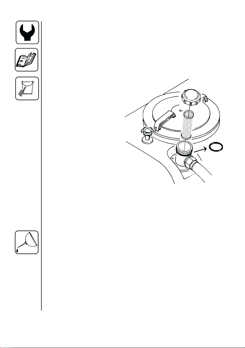
Filters
Clean filters ensure :
• Sprayer components such
as valves, diaphragms
and operating unit are not
hindered or damaged
during operation.
• Nozzle blockages do not
occur whilst spraying.
• Long life of pump. A
blocked suction filter will
result in pump cavitation.
The main filter protecting
sprayer components is the
suction filter at the top of the
tank. Check it regularly.
Ensure the O-ring on filter housing is in good condition and lubricated.
12
The operating unit has an in-built pressure filter. See section on Drain
valve operation.
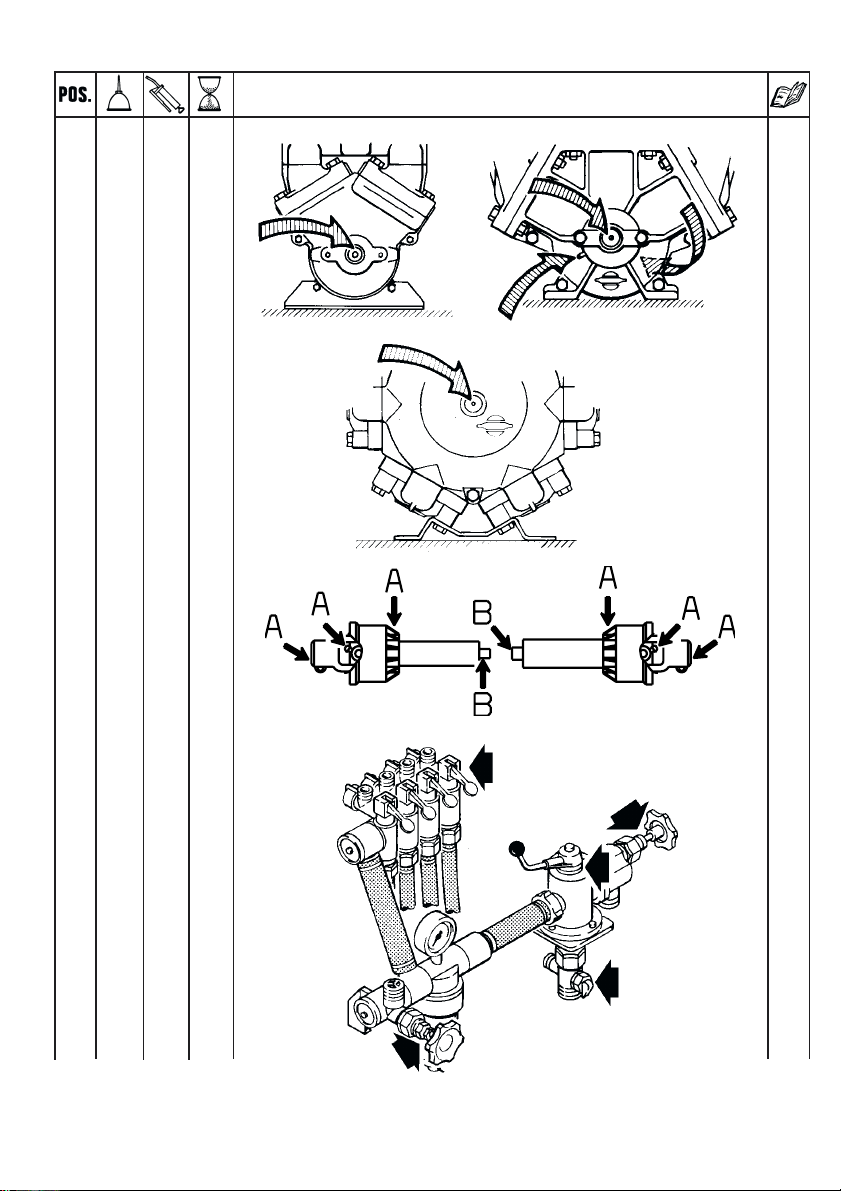
Lubrication
Recommended lubrication is shown in following tables. Use ball
bearing grease (lithium grease No.2)
NOTE: If the sprayers are cleaned with a high pressure cleaner or it
has been used to spray fertilizer, we recommend lubrication of the
entire machine.
Page 13

Position on sprayer
5
Oil
Grease
Operation hours
Page to find more
information
Winter protection or
off-season storage
8
12
11
9
3
10
1-2
13
Page 14
1X 40
1X 40
2
AX 12
BX40
3X 20
20
6
10
11
22
14
Page 15

MB
4X40
MB
5X40
MB
6X40
19
9
18
7X 40
MB
18
15
Page 16

HB
8X 40
HB
9
AX 40
BX 40
HB
19
A
B
9
A
B
A
B
A
B
19
10
AX 40
BX 40
16
B
A
B
A
B
A
Page 17

HB
11 X 40
12
AX 40
BX40
HB
19
A
A
18
B
17
Page 18

Re-adjustment of the boom
After having used the sprayer for some days the boom should be
adjusted as follows:
When adjusting the sprayer must be on level ground with unfolded
boom. For MB booms - Remove the lock pin for trapeze.
MB
HB
MB
Boom breakaway
The function of the breakaway is to prevent or reduce
boom damage if it should
strike an object or the ground.
If it is overtight, it will not
function. If it is too loose, it
will yawn (forward and back
movement) under spraying.
Lubricate coupling before
adjusting spring tension.
Slacken screw nut A to
decrease breakaway resistance. Do not overtighten;
better to loose than overtight.
Again minor adjustments in
the field may be necessary.
For MB boom - Ensure also
channel bolts B are tight.
Outer section
The hinge should be firm. If
overtight it is difficult to fold.
To adjust, tighten or loosen
nuts C.
MB
HB
MB
A
C
C
18
Page 19

Boom lift.
The boom lift should be adjusted so the boom can freely
move up and down when the lift
cylinder is actuated. Do not
tighten so much that the lift
cannot work unhindered.
For MB boom - Adjust D so the
space E is about equal at all 4
points.
MB
MB
E
D
For HB boom - Loosen lock
nuts F and adjust bolts G.
Retighten lock nuts.
Trapeze suspension
For the trapeze to function it
must not be overtight. If it is too
loose the boom will yawn. This
results in a poor spray distribution.
Adjustment is made after
having lubricated all pivot and
friction points (see section on
Lubrication).
Adjust trapeze bolts H so it is
not to tight nor to loose. Minor
adjustment in the field may be
necessary.
Wire tension - HB boom only.
Slack wires result in excessive
boom yawn. To adjust, loosen
rigging screw lock nuts and
turn. If overtightened it will not
be possible to fold arm down.
HB
MB
HB
H
H
F
G
F
HB
G
MB
HB
19
Page 20

Changing of valves and diaphragms
Valves
Dismantle valve compartment 1. Before changing the valves 2 note the
orientation of the valves so that they may be replaced correctly.
Important: For model 361 one special valve with red flap 2A is to be
placed in the valve opening shown.
It is recommended to use new gaskets 3 when changing or checking
the valves.
Diaphragms
Remove the diaphragm cover 4 after having dismantled the valve
compartment as indicated above. The diaphragm 5 may then be
changed. If fluids have reached the crankcase, re-grease the pump
thoroughly. Check also the drain hole at the bottom of the pump is not
blocked.
Model 1202
20
Page 21

Model 1302
Model 361
21
Page 22

Changing of ball seat in operating unit
If problems with on/off valve occurs (dripping nozzles when on/off
valve is closed), the ball and ball seat should be checked.
Remove the 2 bolts fixing the
on/off-pressure valve unit to
the bracket, unscrew the
union nut A and pull the on/
off-pressure valve away from
the distribution valves.
Check the ball for sharp
edges and scratches and
check the ball seat for
cracks and wear - replace if necesary.
A
Nozzle tubes and fittings
Poor seals are usually caused by;
• missing O-rings or gaskets
• damaged or incorrectly seated O-rings
• dry or deformed O-rings or gaskets
• foreign bodies
Therefore, in case of leaks: DO NOT overtighten.
Disassemble, check condition and position of Oring or gasket, clean lubricate and reassemble.
For radial connections only hand tighten them.
22
Lubricate ALL THE WAY ROUND before fitting.
For face connections, a little mechanical leverage may be used.
Page 23

Level indicator
Depending on products used, it can become difficult
to see the red sphere inside the level indicator tube.
Note that the tube can be replaced when necessary.
Off-season storage
When the spraying season is over you should devote
some extra time to the sprayer before it is stored.
Hoses
Check that none of the hoses are caught or have sharp bends.
A leaky hose can give an annoying delay in the middle of the spraying
job. Therefore check all the hoses and change if there is any doubt
about the durability.
Paint
Some chemicals are very hard on paints. It is therefore well advised to
remove rust, if any, and then touch up the paint.
Tank
Check that no chemical residues are left from the last spraying. Chemical residues must not be left in the tank for a long time. It will reduce
the life of the tank. See Spray Technique book - Cleaning the sprayer.
Operating unit
Take care that the safety valve is
completely loosened. The spring is
thereby relieved and operation difficulties are avoided at starting-up next
season.
23
Page 24

Transmission shaft
Check that the transmission shaft fulfills its security purpose, e.g. that
shields and protective tubes are intact.
Anti-freeze precaution
If the sprayer is not stored in a frost- proof place you should take the
following precautions: Put at least 10 litres of 33% anti-freeze mixture
in the tank and let the pump run a few minutes so that the entire
system including spray hose are filled. Remove the glycerine filled
pressure gauge and store it frost free in vertical position.
The anti-freeze solution also hinders the O-rings and gaskets from
drying out.
Operational problems
In cases where breakdowns have occurred the same factors always
seem to come into play:
• Minor leaks on the suction side of the pump will reduce the pump
capacity or stop the suction completely.
• A clogged suction filter will hinder or prevent suction so that the
pump does not operate satisfactorily.
• Clogged up pressure filters will result in increasing pressure at the
pressure gauge but lower pressure at the nozzles.
• Foreign bodies stuck in the pump valves with the result that these
cannot close tightly against the valve seat. This reduces pump
efficiency.
• Poorly reassembled pumps, especially diaphragm covers will allow
the pump to suck air resulting in reduced or no capacity.
24
Therefore ALWAYS check:
1. Suction, pressure and nozzle filters are clean.
2. Hoses for leaks and cracks, paying particular attention to suction
hoses.
3. Gaskets and O-rings are present and in good condition.
4. Pressure gauge is in good working order. Correct dosage depends
on it.
5. Operating unit functions properly. Use clean water to check.
Page 25

Fault Probable cause Control / remedy
Liquid system
No spray from
boom when
turned on.
Air leak on suction.
Check if red suction lid/O-ring are
sealing.
Check suction tube and fittings.
Check tightness of pump diaphragm
and valve covers.
Lack of
pressure.
Pressure
dropping.
Air in system.
Suction/pressure
filters clogged.
Incorrect assembly.
Pump valves blocked
or worn.
Defect pressure
gauge.
Filters clogging.
Nozzles worn.
Tank is airtight.
Sucking air towards
end of tank load.
Fill suction hose with water for initial
prime.
Clean filters.
Check yellow suction pipe is not
obstructed or placed too near the
tank bottom.
Agitation nozzles not fitted.
Too little distance between yellow
suction pipe and tank bottom.
Check for obstructions and wear.
Check for dirt at inlet of gauge.
Clean all filters. Fill with cleaner
water.
If using powders, make sure
agitation is on.
Check flow rate and replace
nozzles if it exceeds 10%.
Check vent is clear.
Excessive agitation, turn off.
Returns inside tank need relocation.
25
Page 26

Fault Probable cause Control / remedy
Pressure
increasing
Pressure filters
beginging to clog.
Clean all filters.
Formation of
foam.
Liquid leaks
from bottom of
pump.
Agitation nozzles
clogged.
Air is being sucked
into system.
Excessive liquid
agitation.
Damaged diaphragm.
Check by turning agitation off/on.
Check tightness / gaskets / O-rings
of all fittings on suction side.
Turn agitation off.
Reduce pump r/min.
Ensure returns inside tank are
present.
Use foam damping addative.
Replace. See Changing of valves
and diaghragms.
26
Page 27

Technical specifications
Measure and weights
LX-MB
Tank Spraying Pump Measure Weight
size width model a x b x c
lm cm kg
10 1202 160 x 226 x 220 309
600 10 1302 160 x 226 x 220 316
12 1302 160 x 226 x 220 324
10 1302 160 x 226 x 220
800 12 1302 160 x 226 x 220
12 361 160 x 226 x 220 404
1000 12 1302 176 x 226 x 220 396
12 361 176 x 226 x 220 418
1200 12 1302 185 x 226 x 220 450
12 361 185 x 226 x 220 468
LX-HB
Tank Spraying Pump Measure Weight
size width model a x b x c
lm cm kg
12 1302 245 x 248 x 215 655
12 361 245 x 248 x 215 679
800 15 1302 330 x 248 x 215 663
15 361 330 x 248 x 215 671
16 361 330 x 248 x 215 683
18 361 330 x 248 x 215 707
12 1302 245 x 248 x 215 693
12 361 245 x 248 x 215 717
1000 15 1302 330 x 248 x 215 701
15 361 330 x 248 x 215 709
16 361 330 x 248 x 215 721
18 361 330 x 248 x 215 745
12 1302 245 x 248 x 215 713
12 361 245 x 248 x 215 737
1200 15 1302 330 x 248 x 215 721
15 361 330 x 248 x 215 729
16 361 330 x 248 x 215 741
18 361 330 x 248 x 215 765
a
c
b
27
Page 28

Power consumption and capacity
1202/9.0
bar l/min kW l/min kW l/min kW l/min kW l/min kW
0 56 0,91 72 1,28 93 1,52 99 1,63 112 1,79
5 40 1,11 53 1,36 66 1,60 71 1,71 79 1,86
10 38 1,38 52 1,74 64 1,79 69 1,87 77 2,07
15 37 1,60 50 1,97 62 2,32 67 2,48 75 2,76
Rotation per min. r/min Capacity l/min Suction height 0,0 m
Power consumption kW Max. pressure 15 bar Weight 24,0 kg
1302/9.0
bar l/min kW l/min kW l/min kW l/min kW l/min kW
0 63 0,90 84 1,19 103 1,51 114 1,61 125 1,80
5 58 0,94 79 1,29 96 1,61 105 1,75 116 1,93
10 56 1,30 76 1,80 94 2,30 101 2,48 111 2,72
15 55 1,80 74 2,22 93 2,92 99 3,18 109 3,54
Rotation per min. r/min Capacity l/min Suction height 0,0 m
Power consumption kW Max. pressure 15 bar Weight 35,0 kg
361/9.5
bar l/min kW l/min kW l/min kW l/min kW l/min kW
0 95 0,92 127 1,33 158 1,56 171 1,69 189 1,85
5 92 1,49 123 1,93 151 2,38 165 2,63 183 2,98
10 91 2,22 120 2,89 148 3,69 163 4,02 180 4,74
15 89 3,03 119 3,92 148 4,90 160 5,40 177 6,15
Rotation per min. r/min Capacity l/min Suction height 0,0 m
Power consumption kW Max. pressure 15 bar Weight 54,0 kg
300 400 500 540 600
300 400 500 540 600
300 400 500 540 600
r/min
r/min
r/min
28
Page 29

Filters and nozzles
Pos. Mesh/ Description/
colour nozzle
2
Pictorial symbols
Description
Function
Connection
Warning
3 - 4
1 30 Suction filter
1
2 50 Pressure filter
3 50 blue Nozzle 4110-16
4 50 blue Nozzle 4110-20
Pressure
Cleaning
Lubrication
Winter storage
Operating
Service/adjustment
Liquid flow
MB
Operational problems
Technical
specifications
Specific boom type
29
Page 30

Page 31

Page 32

Page 33

Page 34

Page 35

Page 36

Page 37

Page 38

Page 39

Page 40

Page 41

Page 42

Page 43

Page 44

Page 45

Page 46

Page 47

Page 48

Notes:
48
32
 Loading...