

Page 1

Contents
EU Declaration of Conformity......................................... 2
Operator safety .............................................................. 3
Description ..................................................................... 4
Function diagram BK operating unit............................... 5
Connecting the sprayer .................................................. 6
Transmission shaft.................................................... 6
Rear lights (if fitted)................................................... 8
Roadworthyness ....................................................... 8
Operating instructions .................................................... 8
Filling the main tank.................................................. 8
Operation of the boom .............................................. 9
Adjustment of the BK controls ................................ 10
Drain valve operation.............................................. 11
Maintenance................................................................. 12
Cleaning the sprayer .................................................... 12
Filters ...................................................................... 14
Lubrication .............................................................. 14
Re-adjustment of the boom .................................... 16
Changing of valves and diaphragms ...................... 17
Changing the ball seat in operating unit....................... 18
Nozzle tubes and fittings......................................... 18
Replacement of transmission
shaft protection guards ........................................... 19
Replacement of transmission shaft cross journals. 19
Off-season storage....................................................... 20
Operational problems................................................... 21
Technical specifications ............................................... 22
Pictorial symbols .......................................................... 25
Spare parts................................................................... 32
JAZZ
Instruction book
674097-GB-98/4
HARDI INTERNATIONAL A/S reserve the right to make changes in design or to add new features
without any obligation in relation to implements purchased before or after such changes.
1
Page 2
EU Declaration of Conformity
Manufacturer,
HARDI INTERNATIONAL A/S
Helgeshøj Allé
DK 2630 Taastrup
DENMARK
Importer,
declare that the following product;
○○○○○○○○○○○○○○○○○○○○○○○○○○○○○○○○○○○○○○○○
○○○○○○○○○○○○○○○○○○○○○○○○○○○○○○○○○○○○○○○○
Adhere extra shipping package labels to inside cover.
A. was manufactured in conformity with the provisions in the COUNCIL
DIRECTIVE of 14 June 1989 on mutual approximation of the laws of the
Member States on the safety of machines (89/392/EEC as amended by
directives 91/368/EEC and 93/368/EEC) with special reference to Annex 1
of the Directive on essential safety and health requirements in relation to
the construction and manufacture of machines.
B. was manufactured in conformity with the standards current at that time
that implements a harmonised standard in accordance with Article 5 (2)
and other relevant standards.
Taastrup 1.4.98
Erik Holst
Managing Director
HARDI INTERNATIONAL A/S
2
Page 3
Operator safety
Watch for this symbol . It means WARNING, CAUTION, NOTE.
Your safety is involved so be alert!
Note the following recommended precautions and safe operating
practices.
Read and understand this instruction book before using the Read
and understand the instruction book before using the equipment. It is
equally important that other operators of this equipment read and
understand the book.
Local law may demand that the operator be certified to use spray
equipment. Adhere to the law.
Pressure test with clean water prior to filling with chemicals.
Wear protective clothing.
Rinse and wash equipment after use and before servicing.
Depressurize equipment after use and before servicing.
Never service or repair the equipment whilst it is operating.
Disconnect electrical power before servicing.
Always replace all safety devices or shields immediately after servic-
ing.
If an arc welder is used on the equipment or anything connected to
the equipment, disconnect power leads before welding. Remove all
inflammable or explosive material from the area.
Do not eat, drink or smoke whilst spraying or working with contaminated equipment.
Wash and change clothes after spraying.
Wash tools if they have become contaminated.
In case of poisoning, seek doctor or ambulance. Remember to
identify chemicals used.
Keep children away from the equipment.
Do not attempt to enter the tank.
If any portion of the instruction book remains unclear after reading it,
contact your HARDI dealer for further explanation before using the
equipment.
3
Page 4
We congratulate you for choosing a HARDI plant protection product. The
reliability and efficiency of this product depend on your care. The first step
is to carefully read and pay attention to this instruction book. It contains
essential information for the efficient use and long life of this quality product.
As the instruction book covers all JAZZ models, please
pay attention to the paragraphs dealing with precisely
your model. This book is to be read in conjunction with the
Spray Technique book.
Lifting points
When loading or unloading the sprayer from a truck or
lorry with a crane, use the lifting points as shown.
Description
The HARDI JAZZ tractor mounted sprayers are designed for the application of pesticides and liquid fertilizers in parks, gardens and amenity areas.
They consist of a pump, a frame with tank of 200 litre capacity, BK 180
operating unit, a 6, 8 or 10 metre SB boom, 15 litre clean water tank,
transmission shaft and calibration kit
The diaphragm pump is simple, with easily accessible diaphragms and
valves that ensures liquid does not come in contact with the vital parts of
the pump.
The tank with basket filter is made of impact-proof and chemical resistant
polyethylene. It has a purposeful design with no sharp edges for easy
cleaning. A suction filter is located inside the tank at the sump. The
standard filling hose holder reduces the risk of mishaps at filling.
The BK 180 K operating unit consists of; agitator, safety valve, on/off
function, pressure filter with pressure gauge, distribution valves with
pressure equalization device, an extra valve for lance or spray gun and
HARDI-MATIC. A constant volume per hectare of the liquid at varying
speed in the same gear is ensured with HARDI-MATIC.
The SB boom is bolted to the tank frame and is fitted with spring loaded
breakaways at the pivots. The TRIPLET nozzle holders allow for quick
nozzle selection.
4
Page 5
Identification plates
An identification plate fitted on the frame and pump is to indicate model,
serial number and country of origin. If ordering spare parts, inform your
dealer of these so the right model and version are described.
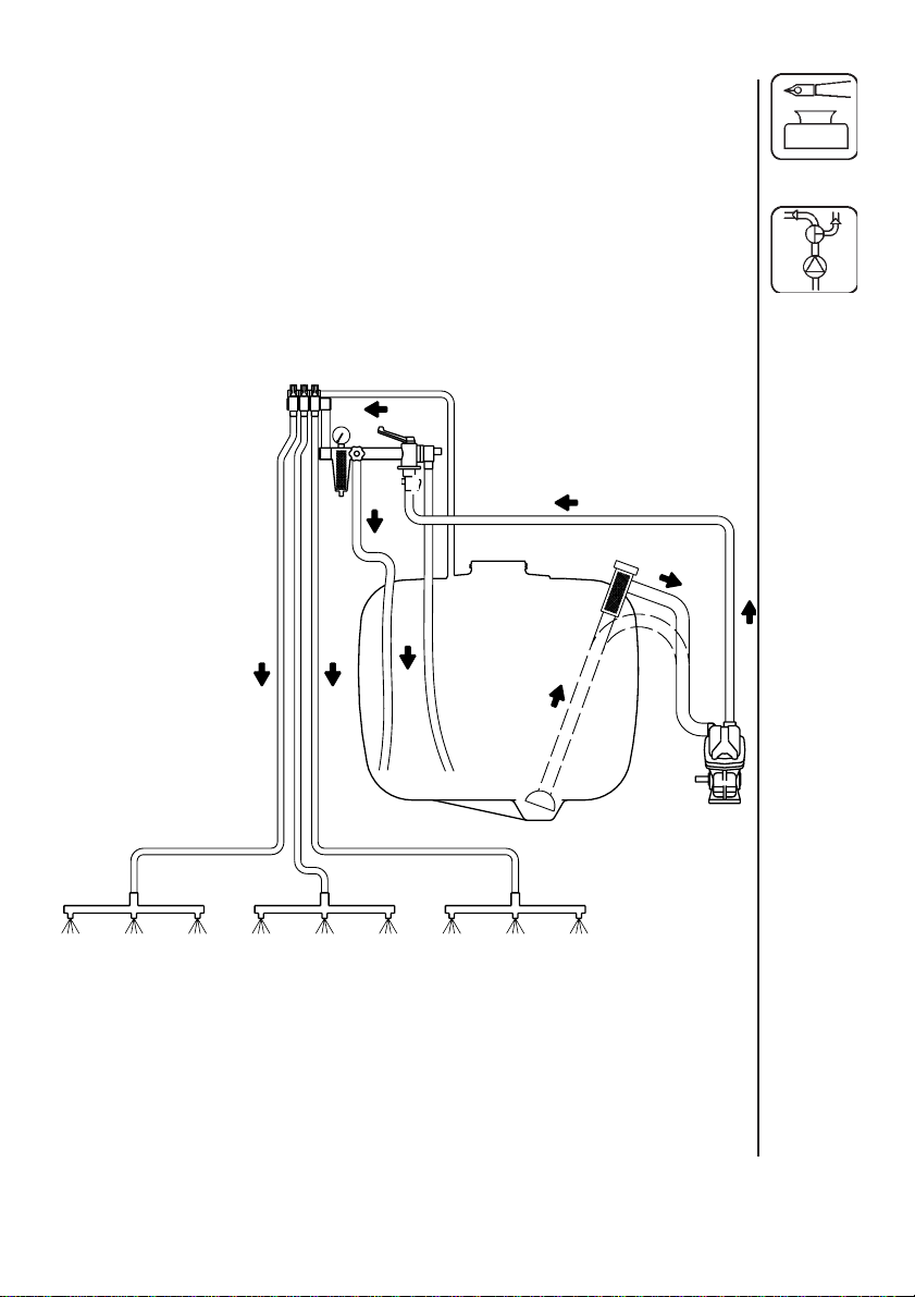
Function diagram BK operating unit
1. Suction filter
2. Pump
3. Agitator
4. Safety valve
5. On/off valve
6. Pressure filter with pressure gauge
7. Distribution valve with pressure equalization
8. HARDI-MATIC
9. Sprayer boom
7
5
4
8
6
3
1
2
9
5
Page 6
Connecting the sprayer
The sprayer is designed for three point suspension and is equipped with
22 mm pivots (category I).
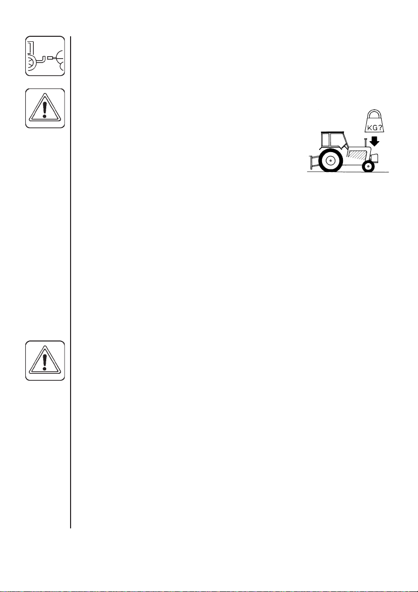
WARNING: Note the weight of the sprayer. General recommendations are
as follows:
• Add ballast to front of tractor.
• Increase tyre pressure
(see tractor instruction book).
• Be careful when filling/lifting the sprayer for
the first time.
• Ensure the operating unit and tractor do not touch.
• Travel at slower speeds when driving with a full tank.
(The tractor braking effect will be reduced.)
Transmission shaft
Operator safety
To avoid accidents and personal injuries, note the following recommended
precautions and safe operation practices.
Always STOP ENGINE before attaching the transmission shaft to tractor
P.T.O. - most tractor P.T.O. shafts can be rotated by hand to facilitate
spline alignment, when engine is stopped.
When attaching the shaft, make sure that the snap lock is FULLY ENGAGED - push and pull shaft until it locks.
WARNING: ROTATING TRANSMISSION SHAFTS WITHOUT PROTECTION GUARDS ARE FATAL
Always keep protection guards and chains intact and make sure that it
covers all rotating parts, including cross journals at each end of the shaft.
Do not use without protection guard.
Do not touch or stand on the transmission shaft when it is rotating - safety
distance: 1.5 metre.
Prevent protection guards from rotating by attaching the chains allowing
sufficient slack for turns.
Make sure that protection guards around tractor P.T.O. and implement
shaft is intact.
6
Page 7
Always STOP ENGINE and remove the ignition key before carrying out
maintenance or repairs to the transmission shaft or implement.
Installation of transmission shaft
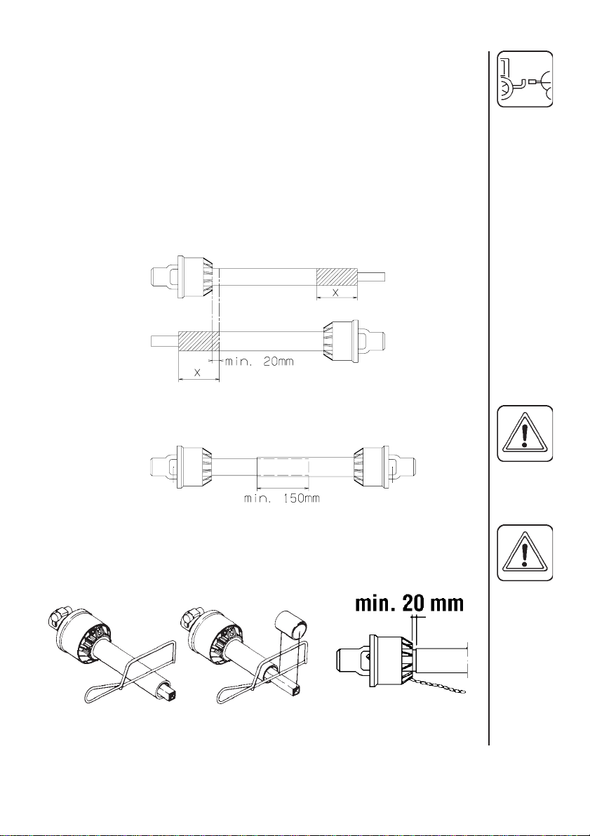
Initial installation of the shaft is done as follows:
1. Attach sprayer to tractor and set sprayer in the position with shortest
distance between the tractor and sprayer pump P.T.O. shafts.
2. Stop engine and remove ignition key.
3. If transmission shaft must be shortened, the shaft is pulled apart. Fit the
two shaft parts at tractor and sprayer pump and measure how much it
is necessary to shorten the shaft. Mark the protection guards.
Note: The shaft must always have a minimum overlap 150 mm.
4. The two parts are shortened equally. Use a saw, and file the profiles
afterwards to remove burrs.
5. Grease the profiles, and assemble male and female parts again.
7
Page 8
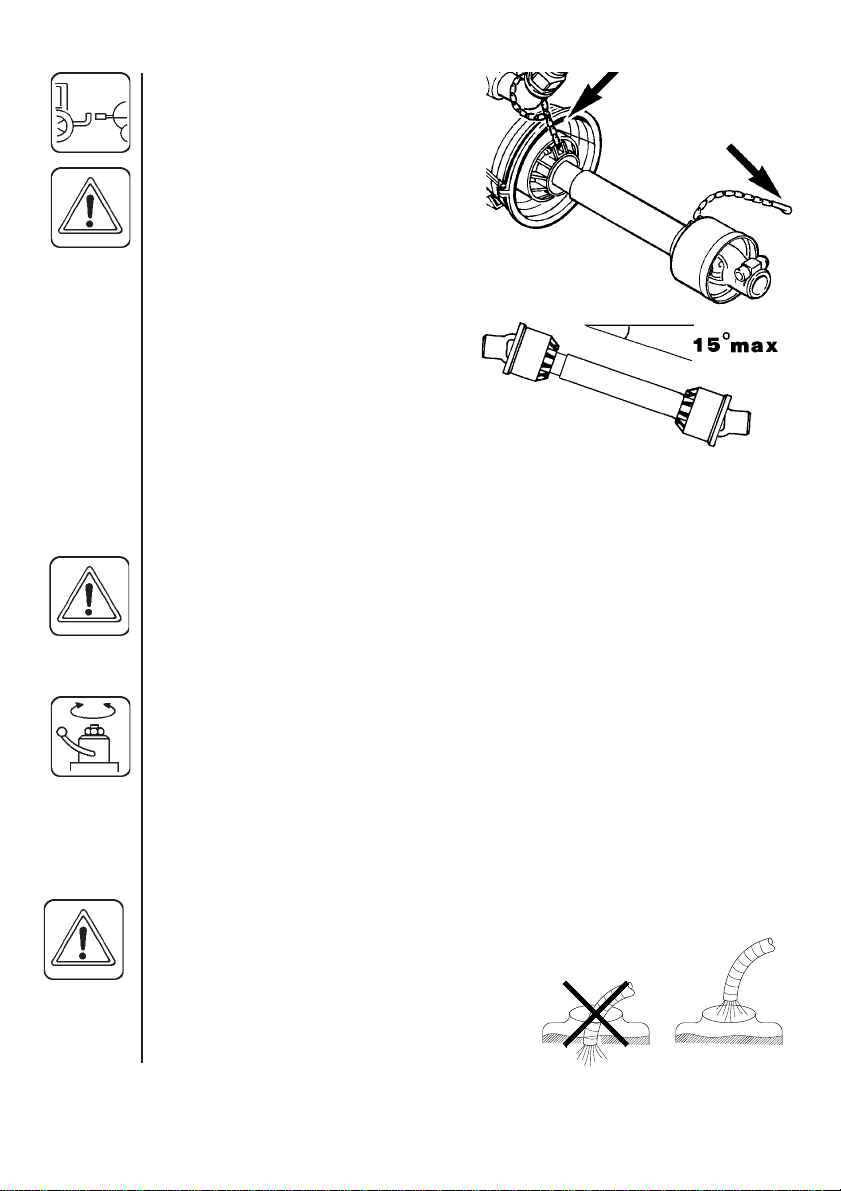
6.Fit the shaft to tractor and sprayer
pump.
NOTE: Female part towards tractor.
Fit the chains to prevent the
protection guards to rotate with the
shaft.
7.To ensure long life of the transmission shaft, try to avoid working
angles greater than 15°.
8.Transmission shafts with cone
must be fitted by tightening the
Allen screw to a torque of 40 Nm.
Check again after 2 minutes use.
Rear lights (if fitted)
Connect plug for rear lights to the tractors 7-poled
socket and check that rear lights, stop lights and direction
indicators work properly before driving anywhere.
The wiring is in ISO accordance. See section on Technical specifications.
Roadworthyness
When driving on public roads and other areas where the highway code
applies, or areas where there are special rules and regulations for marking
and lights on implements, you should observe these and equip implements
accordingly.
Operating instructions
Filling the main tank
Water is filled into the tank by removing the tank lid located at right hand
side of sprayer tank. It is recommended to use as clean water as possible
for spraying purposes. Always fill water through the strainer basket to
prevent foreign particles from entering the tank. An overhead tank can be
used in order to obtain high filling capacity.
WARNING: Do not let the filling hose enter the tank. Keep it outside the
tank, pointing towards the filling hole.
If the hose is lead into the tank and the
water pressure drops at the water supply
plant, chemicals may be siphoned back
and contaminate the water supply lines,
plant and well.
8
Page 9
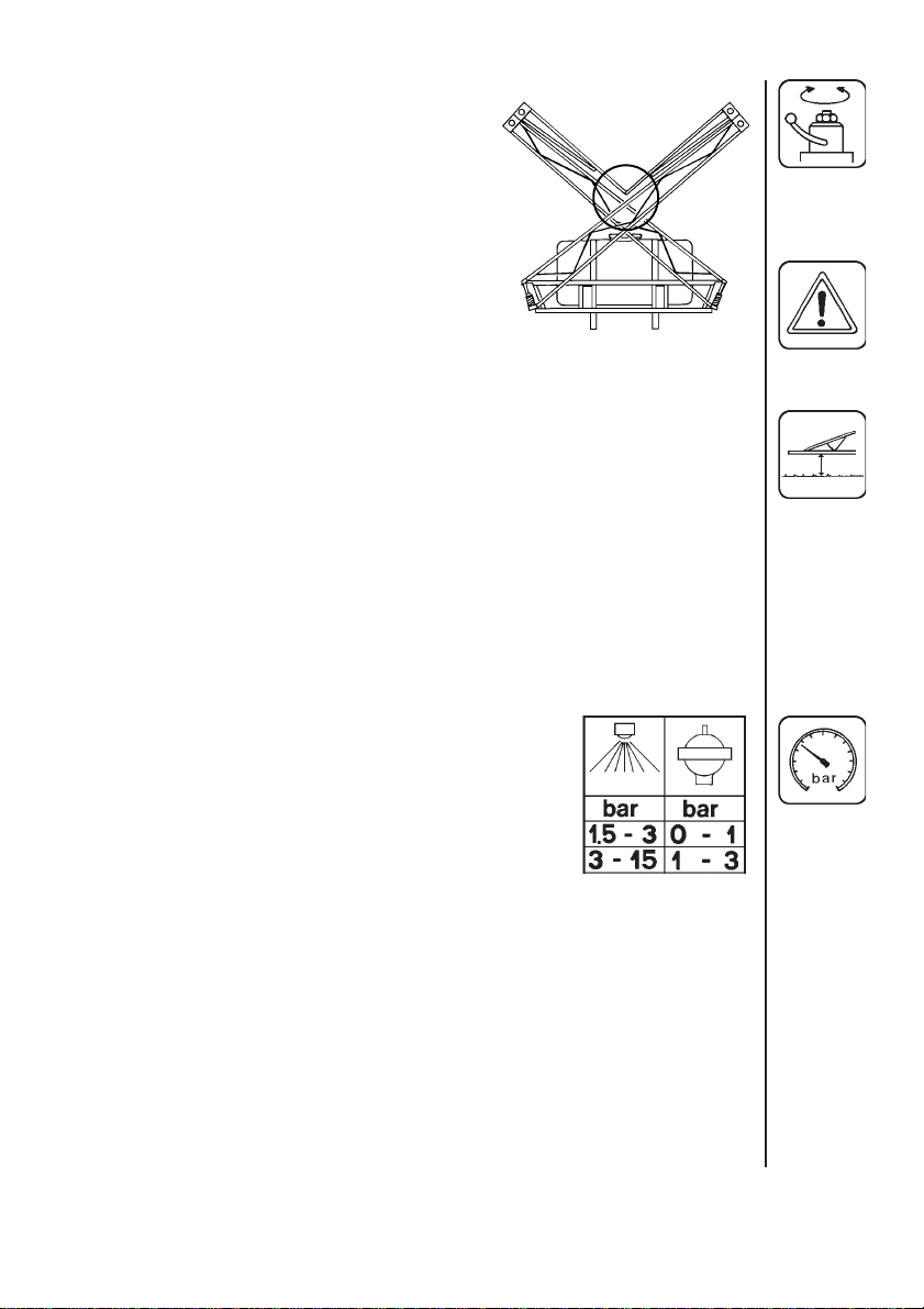
Operation of the boom
Remove boom transport lock pin if fitted.
When unfolding (or folding) the initial force
to release the spring loaded breakaways
will be higher than the actual unfolding/
folding.
CAUTION: The breakaways must be
correctly tensioned and lubricated.
(see section on Boom breakaway)
Replace boom transport lock pin when
driving with folded boom.
Boom height
Correct boom height is very important in order to achieve the most optimal
spray pattern. (See Spray Technique book).
Small adjustments of the boom height can usually be made with the 3point suspension from the tractor - raising or lowering the sprayer.
On grounds where greater adjustments are needed the boom height can
be changed manually by removing the 4 bolts holding the boom to the
frame.
Note: This is best done by 2 persons or with a mechanical hoist.
Pulsation damper
The air pressure in the pulsation damper is pre-set at
the factory to 2 bar. This covers spray working
pressures between 3 and 15 bar. When using spray
pressures outside this range, the air pressure should
be adjusted as shown in the diagram. The diagram is
also embossed on the damper.
9
Page 10
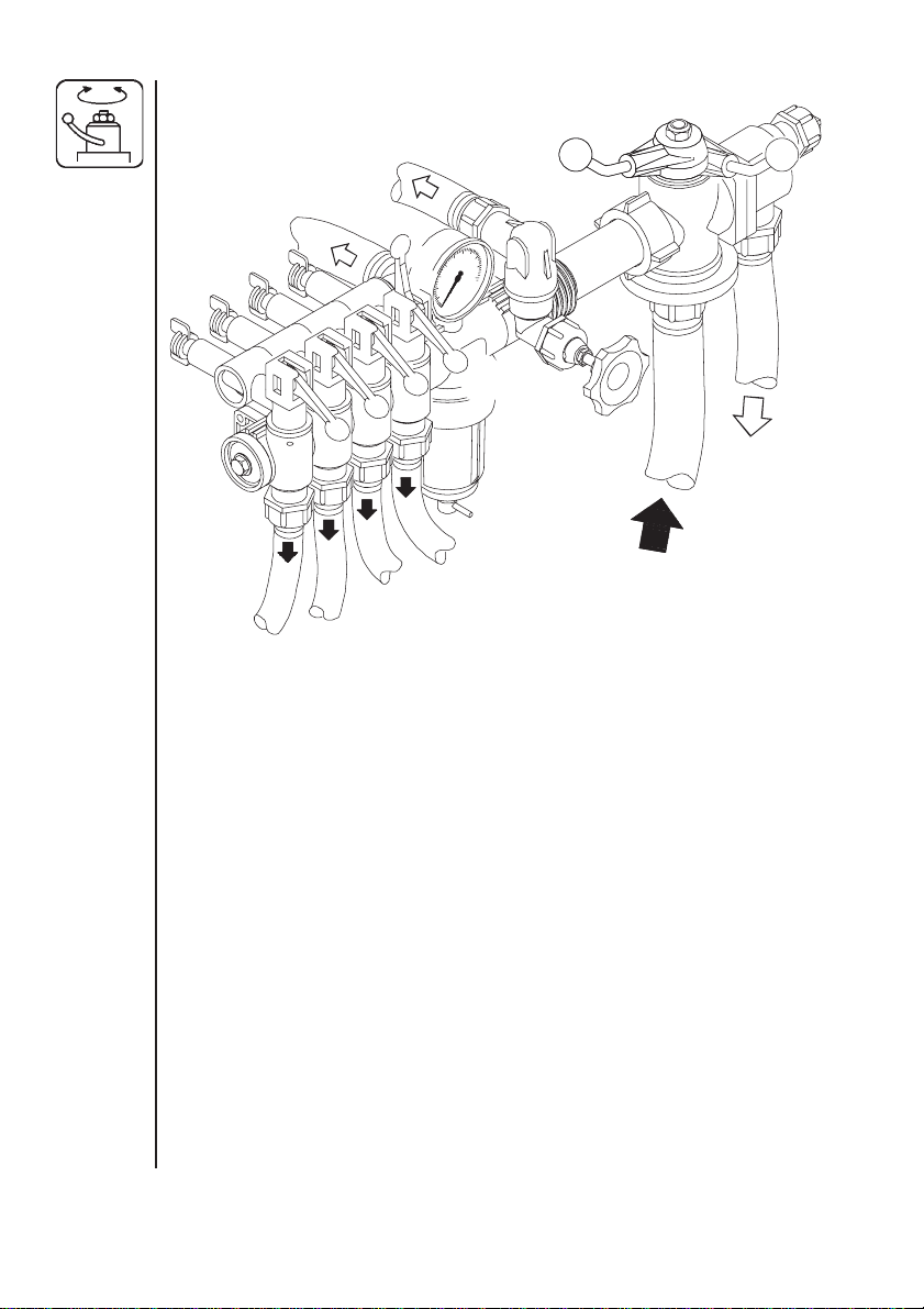
Adjustment of the BK controls
B
2
A
B
5
3
A
4
1.Choose the correct nozzle. Make sure that all nozzles are the same
type and capacity. See “Spray Technique” book.
2.Turn main ON/OFF handle 2 to ON position A.
3.Set all hand levers 3 on the distribution valve to ON position A.
4.Turn the HARDI-MATIC valve 4 anti-clockwise to its extreme position.
5.Put the tractor in neutral and adjust the P.T.O. thereby the number of
revolutions of the pump corresponding to the intended travelling speed.
Note: The P.T.O. revolutions must be kept between 300-600 r/min.
6.Adjust the HARDI-MATIC valve 4 so that the pressure gauge indicates
the recommended pressure.
10
ADJUSTMENT OF PRESSURE EQUALIZATION:
7.Place the first lever 3 on the distribution valve in OFF position B.
8.Turn the adjusting screw 5 until the pressure gauge again shows the
same pressure.
9.Adjust the other sections of the distribution valve in the same way.
Hereafter adjustment of pressure equalization will only be needed if you
change to nozzles of other capacities.
Page 11

10. Operating the control unit while driving:
To stop the liquid flow to the boom turn the ON/OFF handle 2 to OFF
position B. This returns the pump output to the tank through the return
system. The diaphragm anti-drip valves ensure instantaneous closing
of all nozzles.
To stop the liquid flow to one or more boom sections, turn lever 3 of the
distribution valve to OFF position B for the section to be closed. The
pressure equalization ensures that the pressure does not rise in the
sections which are to remain open.
Drain valve operation
A drain valve cap is located under the tank. Unscrew it to drain tank. Be
careful not to loose the seal.
Spray Technique - see separate book.
Optional Extras - see separate books.
11
Page 12

Maintenance
In order to derive full benefit from the sprayer for many years the following
few but important rules should be kept:
Cleaning the sprayer
Guidelines
Read the whole label of the chemical. Take note of any particular instructions regarding recommended protective clothing, deactivating agents, etc.
Read the detergent and deactivating agent labels. If cleaning procedures
are given, follow them closely.
Be familiar with local legislation regarding disposal of pesticides washings,
mandatory decontamination methods, etc. Contact the appropriate body,
e.g. Dept of Agriculture.
Pesticide washings can usually be sprayed out on a soakaway. This is an
area of ground that is not used for cropping. You must avoid seepage or
run-off of residues into streams, water courses, ditches, wells, springs, etc.
The washings from the cleaning area must not enter sewers. Drainage
must lead to a soakaway.
Cleaning starts with the calibration, as a well calibrated sprayer will ensure
the minimal amount of remaining spray liquid.
It is good practice to clean the sprayer immediately after use thereby
rendering the sprayer safe and ready for the next pesticide application.
This also prolongs the life of the components.
12
It is sometimes necessary to leave spray liquid in the tank for short periods, e.g. overnight, or until the weather becomes suitable for spraying
again. Unauthorized persons and animals must not have access to the
sprayer under these circumstances.
If the product applied is corrosive, it is recommended to coat all metal
parts of the sprayer before and after use with a suitable rust inhibitor.
Remember: Clean sprayers are safe sprayers.
Clean sprayers are ready for action.
Clean sprayers can not be damaged by pesticides and
their solvents.
Page 13

Cleaning
1.Dilute remaining spray liquid in the tank with at least 10 parts water and
spray the liquid out in the field you have just sprayed.
NOTE: It is advisable to increase the forward speed (double if possible)
and reduce the pressure. For S4110 nozzles, pressure may be reduced
to 1.5 bar.
2.Select and use the appropriate protective clothing. Select detergent
suitable for cleaning and suitable deactivating agents if necessary.
3.Rinse and clean sprayer and tractor externally. Use detergent if necessary.
4.Remove tank and clean. Be careful not to damage the mesh. Replace
when the sprayer is completely clean.
5.With the pump running, rinse the inside of the tank. Remember the tank
roof. Rinse and operate all components and any equipment that has
been in contact with the chemical.
Before opening the distribution valves and spraying the liquid out,
decide whether this should be done in the field again or on the
soakaway.
6.After spraying the liquid out, stop the pump and fill at least 1/5 of the
tank with clean water. Note that some chemicals require the tank to be
completely filled. Add appropriate detergent and/or deactivating agent,
e.g. Washing soda or Triple ammonia.
NOTE: If a cleaning procedure is given on the chemical label, follow it
closely.
7.Start the pump and operate all controls enabling the liquid to come in
contact with all the components. Leave the distribution valves until last.
Some detergents and deactivating agents work best if left in the tank
for a short period. Check the label.
8.Drain the tank and let pump run dry. Rinse inside of tank, again letting
the pump run dry.
9. Stop the pump. If the pesticides used have a tendency to block nozzles
and filters, remove and clean them now.
10. Replace all the filters and nozzles and store the sprayer. If, from
previous experiences, it is noted that the solvents in the pesticide are
particularly aggressive, store the sprayer with the tank lid open.
NOTE: If the sprayer is cleaned with a high pressure cleaner we
recommend lubrication of the entire machine.
13
Page 14

Filters
Clean filters ensure :
• Sprayer components such as valves, diaphragms and operating unit are
not hindered or damaged during operation.
• Nozzle blockages do not occur whilst spraying.
• Long life of pump. A blocked suction filter will result in pump cavitation.
The main filter protecting sprayer components is the suction filter inside
the tank at the sump. Check it regularly. Also regularly check nozzle filters.
BK Pressure filter / In Line Filters (if fitted)
The BK operating unit has a built-in pressure filter. Unscrew the filter bowl
to inspect and clean the filter.
The boom may be equipped with In Line Filters. Unscrew the filter bowl to
inspect and clean the filter.
Lubrication
Recommended lubrication is shown in following tables. Use ball bearing
grease (lithium grease No.2)
NOTE: If the sprayers are cleaned with a high pressure cleaner or it has
been used to spray fertilizer, we recommend lubrication of the entire
machine.
Position on sprayer
5
Operation hours
14
Oil
Grease
Page to find more
information
Winter protection/
off-season storage
Page 15

1X40
17
2
AX 12
BX40
3X40
4X40
6
7
19
10
18
8m SB
16
15
Page 16

Re-adjustment of the boom
After having used the sprayer for some days the boom should be adjusted
as follows:
When adjusting the sprayer must be on level ground with unfolded boom.
Boom breakaway
The function of the breakaway is
to prevent or reduce boom
damage if it should strike an
object or the ground. If it is overtight, it will not function. If it is
too loose, it will yawn (forward
and back movement) under
spraying.
Lubricate coupling before
adjusting spring tension. Slacken screw nut A to decrease breakaway
resistance. Do not overtighten; better to loose than over-tight. Again minor
adjustments in the field may be necessary.
Ensure also channel bolts B are tight.
16
Outer section (8m boom)
The hinge should be firm. If
overtight it is difficult to fold. To
adjust, tighten or loosen nuts C.
C
C
Page 17

Changing of valves and diaphragms
Valves
Dismantle valve compartment (1). Before changing the valves (2) note the
orientation of the valves so that they may be replaced correctly.
It is recommended to use new gaskets (3) when changing or checking the
valves.
Diaphragms
Remove the diaphragm cover (4) after having dismantled the valve compartment as indicated above. The diaphragm (5) may then be changed. If
fluids have reached the crankcase, re-grease the pump thoroughly. Check
also the drain hole at the bottom of the pump is not blocked.
Model 1202
Pump Valve cover Diaphragm cover Diaphragm bolt
Model Nm Nm Nm
1202 70 70 60
1 Nm = 0.74 ft-lb
17
Page 18

Changing the ball seat in operating unit
If the main ON/OFF valve does not seal properly (dripping nozzles when
main ON/OFF valve is closed), the ball and seat should be
checked.
Remove the 2 bolts fixing the main ON/OFFpressure valve unit to the bracket, unscrew
the union nut A and pull the valve
away from the distribution
valves.
Check the ball for
sharp edges and
scratches, and check
the ball seat for cracks
and wear - replace if
necessary.
Nozzle tubes and fittings
Poor seals are usually caused by:
• Missing O-rings or gaskets
• Damaged or incorrectly seated O-rings
• Dry or deformed O-rings or gaskets
• Foreign bodies
A
18
Therefore, in case of leaks: DO NOT over-tighten.
Disassemble, check condition and position of Oring or gasket, clean lubricate and reassemble.
For radial connections only hand tighten them.
The O-ring to be lubricated ALL THE WAY ROUND before fitting on to the
nozzle tube.
For axial connections, a little
mechanical leverage may be used.
Page 19

Replacement of transmission shaft protection guards
The replacement of defective protection guards is easy to do.
1. Remove bolt A, lock B and
grease nipple C. Twist universal
cross cover 1/4 turn and pull it
backwards.
2. Remove the synthetic bearings
and protection tube.
2a.Remove inner bush from
protection tube.
3. Assemble again in reverse
order, using new parts where
necessary. Remember to fit
chains again.
4. Grease bearings.
Use only genuine HARDI spare
parts to service the transmission shaft.
Replacement of transmission shaft cross journals.
1. Remove protection guard as
described previously.
2. Remove Seeger circlip rings
3. Press the cross journal
sidewards - use hammer and
mandrel if necessary.
4. Remove needle bearing cups
and cross journal can now be
removed.
5. Carefully remove needle bearing
cups from new cross journal and
install it in reverse order. Before
fitting the needle bearing cups
again, check that needles is
placed correctly. Avoid dust and
dirt in the new bearings.
19
Page 20

Off-season storage
When the spraying season is over you should devote some extra time to
the sprayer before it is put away.
Hoses
Check that none of the hoses are caught or have sharp bends.
A leaky hose can give an annoying delay in the middle of the spraying job.
Therefore check all the hoses and change if there is any doubt about the
durability.
Paint
Some chemicals are very hard on paints. It is therefore well advised to
remove rust, if any, and then touch up the paint.
Tank
Check that no chemical residues are left from the last spraying. Chemical
residues must not be left in the tank for a long time. It will reduce the life of
the tank. See Cleaning the sprayer.
Anti-freeze precaution
If the sprayer is not stored in a frost-proof place you should take the
following precautions: Put at least 5 litres of 33% anti-freeze mixture in the
tank and let the pump run a few minutes so that the entire system including spray hose are filled. Remove the glycerine filled pressure gauge and
store it frost free in vertical position.
The anti-freeze solution also hinders the O-rings and gaskets from drying
out.
20
Page 21

Operational problems
In cases where breakdowns have occurred the same factors always seem
to come into play:
• Minor leaks on the suction side of the pump will reduce the pump
capacity or stop the suction completely.
• A clogged suction filter will hinder or prevent suction so that the pump
does not operate satisfactorily.
• Clogged up pressure filters will result in increasing pressure at the
pressure gauge but lower pressure at the nozzles.
• Foreign bodies stuck in the pump valves with the result that these
cannot close tightly against the valve seat. This reduces pump efficiency.
• Poorly reassembled pumps, especially diaphragm covers will allow the
pump to suck air resulting in reduced or no capacity.
Therefore ALWAYS check:
1. Suction and nozzle filters are clean.
2. Hoses for leaks and cracks, paying particular attention to suction hoses.
3. Gaskets and O-rings are present and in good condition.
4. Pressure gauge is in good working order. Correct dosage depends on it.
5. Operating unit functions properly. Use clean water to check.
21
Page 22

Fault Probable cause Control / remedy
No spray from
blower when
turned on.
Lack of
pressure.
Pressure
dropping.
Air leak on suction.
Air in system.
Suction / nozzle
filters clogged.
Incorrect assembly.
Pump valves blocked
or worn.
Defect pressure gauge.
Filters clogging.
Check suction tube and fittings.
Check tightness of pump diaphragm
and valve covers.
Fill suction hose with water for initial
prime.
Clean filters.
Recheck assembly.
Check for obstructions and wear.
Check for dirt at inlet of gauge.
Clean all filters. Fill with cleaner
water.
Pressure
increasing.
Formation of
foam.
Liquid leaks
from bottom of
pump.
Nozzles worn.
Tank is airtight.
Nozzle filters begin-
ning to clog.
Air is being sucked
into system.
Excessive liquid
agitation.
Damaged diaphragm.
Check flow rate and replace nozzles
if it exceeds 10%.
Check vent is clear.
Clean all filters.
Check tightness / gaskets / O-rings
of all fittings on suction side.
Use foam damping additive.
Replace. See section Changing
valves and diaphragms.
Technical specifications
Pump power consumption and capacity
1202/9.0
bar l/min kW l/min kW l/min kW l/min kW l/min kW
0 56 0,91 72 1,28 93 1,52 99 1,63 112 1,79
5 40 1,11 53 1,36 66 1,60 71 1,71 79 1,86
10 38 1,38 52 1,74 64 1,79 69 1,87 77 2,07
15 37 1,60 50 1,97 62 2,32 67 2,48 75 2,76
Rotation per min. r/min Capacity l/min Suction height 0,0 m
Power consumption kW Max. pressure 15 bar Weight 24,0 kg
300 400 500 540 600
r/min
22
Page 23

Measure and weights
Tank Min. Max. ABCDE
size boom height boom height
l H mm H mm mm mm mm mm mm
200 180 755 680 380 588 22 26
Tank Spraying Pump Measure Weight
size width model a x b x c
lm cm kg
200 8 1202 100 × 190 × 216 170
6 1202 110 × 190 × 176 149
10 1202 100 × 190 × 216 175
c
ba
23
Page 24

Filters and nozzles
Pos. Mesh/ Description/
2
1
3 - 4
1 30 Suction filter
2 50 Pressure filter
3 50 blue Nozzle 4110-20
4 50 blue Nozzle 4110-24
Temperature and pressure ranges
Operating temperature range: 20 to 40° C.
Operating pressure for safety valve: 15 bar
Rear lights
Position Wire colour
1. LHS direction indicator Yellow
2. Free Blue
3. Frame White
4. RHS direction indicator Green
5. RHS rear position lamp Brown
6. Stop lamps Red
7. LHS rear position lamp Black
colour nozzle
50 blue Nozzle 4110-36
24
Materials and recycling
Tank HDPE
Hoses PVC
Valves mainly glass-filled PA.
Fittings PA
Disposal of the sprayer
When the equipment has completed its working life, it must be thoroughly
cleaned. The tank, hose and synthetic fittings can be incinerated at an
authorized disposal plant. The metallic parts can be scrapped. Always
follow local legislation regarding disposal.
Page 25

Pictorial symbols
Description
Function
Connection
Warning
Operating
Service/adjustment
Liquid flow
Pressure
Cleaning
Lubrication
Winter storage
Operational problems
Technical specifications
25
Page 26

26
A10 1202/foot
Page 27

Unit BK 180K (92) B9
27
Page 28

B13 Distributor BK 180K (94)
28
Page 29

Damper HJ73 B300
29
Page 30

D2 SB 6/8/10 m
30
Page 31

Boom tube SNAP FIT D903
31
Page 32

E2 BL 200/300
32
Page 33

15 l Clean water tank K107
33
Page 34

HARDI INTERNATIONAL A/
HELGESHØJ ALLÉ 38 • DK 2630 TAASTRUP • DENMARK
S
0396
EN 1152 / ISO 5674
POS.
AX 8
BX 40
rpm kW Nm
540 12 210
1000 18 172
HARDI
978389
K604 Shaft (94)
34
Page 35

Notes:36Notes:
35
Page 36

 Loading...