

Page 1

BOSS/HERON
Instruction book
673791
GB - 04.2002
www.hardi-international.com
Page 2

We congratulate you for choosing a HARDI plant protection
product. The reliability and efficiency of this product depend
upon your care. The first step is to carefully read and pay attention to this instruction book. It contains essential information
for the efficient use and long life of this quality product.
llustrations, technical information and data in this book are to the best of our belief
correct at the time of printing. As it is HARDI INTERNATIONAL A/S policy permanently to
improve our products, we reserve the right to make changes in design, features,
accessories, specifications and maintenance instructions at any time and without notice.
HARDI INTERNATIONAL A/S is without any obligation in relation to implements
purchased before or after such changes.
HARDI INTERNATIONAL A/S cannot undertake any responsibility for possible omissions
or ina ccurac ies in this pub lic ati on, alt hou gh e ver ything p oss ible has been do ne to ma ke
it complete and correct.
.As this instruction book covers more models and features or equipment, which are
available in certain countries only, please pay attention to paragraphs dealing with
precisely your model.
Published and printed by HARDI INTERNATIONAL A/S
Page 3

Contents
EC Declaration of Conformity................................................... 2
Operator safety ........................................................................ 3
Description ............................................................................... 4
Function diagram ..................................................................... 5
Connecting the sprayer............................................................5
Transmission shaft ............................................................. 6
Mechanical remote control - HR only ................................. 8
Rear lights (if fitted) ............................................................ 8
Roadworthyness ................................................................ 8
Operating instructions .............................................................. 8
Filling the tank .................................................................... 8
Unfolding and folding the boom.......................................... 9
Boom height ....................................................................... 9
Pulsation damper ............................................................... 9
Adjustment of the BK controls..........................................10
Maintenance .......................................................................... 12
Cleaning the sprayer ........................................................ 12
Filters ............................................................................... 14
Lubrication ....................................................................... 15
Re-adjustment of the boom..............................................18
Recommended tyre pressure (only HR)........................... 18
Wheel nuts and bearings (only HR) ................................. 19
Changing of valves and diaphragms................................19
Changing the ball seat in operating unit........................... 20
Nozzle tubes and fittings .................................................. 20
Off-season storage........................................................... 21
Operational problems............................................................. 22
Technical specifications.......................................................... 24
Pictorial symbols .................................................................... 26
Assembly................................................................................ 27
Spare parts ............................................................................ 45
BOSS/HERON
Instruction book
673791-GB-04/2002
HARDI INTERNATIONAL A/S reserve the right to make changes in design or to add new features without
any obligation in relation to implements purchased before or after such changes.
1
Page 4
EC Declaration of Conformity
Manufacturer,
HARDI INTERNATIONAL A/S
Helgeshøj Allé 38
DK 2630 Taastrup
DENMARK
Importer,
declare that the following product;
○○○○○○○○○○○○○○○○○○○○○○○○○○○○○○○○○○○○○○○○
○○○○○○○○○○○○○○○○○○○○○○○○○○○○○○○○○○○○○○○○
Adhere extra shipping package labels to inside cover.
A. was manufactured in conformity with the provisions in the COUNCIL
DIRECTIVE of 14 June 1989 on mutual approximation of the laws of the
Member States on the safety of machines (89/392/EEC as amended by
directives 91/368/EEC and 93/368/EEC) with special reference to Annex 1
of the Directive on essential safety and health requirements in relation to
the construction and manufacture of machines.
B. was manufactured in conformity with the standards current at that time
that implements a harmonised standard in accordance with Article 5 (2) and
other relevant standards.
Taastrup 03.04.2002
Lars Bentsen
Product Development Manager
HARDI INTERNATIONAL A/S
2
Page 5

Operator safety
Watch for this symbol . It means WARNING, CAUTION,
NOTE. Your safety is involved so be alert!
Note the following recommended precautions and safe operating
practices.
Read and understand this instruction book before using the
equipment. It is equally important that other operators of this
equipment read and understand this book.
Local law may demand that the operator be certified to use spray
equipment. Adhere to the law.
Pressure test with clean water prior to filling with chemicals.
Wear protective clothing.
Rinse and wash equipment after use and before servicing.
Depressurize equipment after use and before servicing.
Never service or repair the equipment whilst it is operating.
Disconnect electrical power before servicing.
Always replace all safety devices or shields immediately after
servicing.
If an arc welder is used on the equipment or anything connected
to the equipment, disconnect power leads before welding. Remove all inflammable or explosive material from the area.
Do not eat, drink or smoke whilst spraying or working with contaminated equipment.
Wash and change clothes after spraying.
Wash tools if they have become contaminated.
In case of poisoning, seek doctor or ambulance. Remember to
identify chemicals used.
Keep children away from the equipment.
Do not attempt to enter the tank.
If any portion of this instruction book remains unclear after read-
ing it, contact your HARDI dealer for further explanation before
using the equipment.
3
Page 6

We congratulate you for choosing a HARDI plant protection product.
The reliability and efficiency of this product depend on your care. The
first step is to carefully read and pay attention to this instruction
book. It contains essential information for the efficient use and long life
of this quality product.
As the instruction book covers all BOSS (BS) and HERON (HR) models, please pay attention to the paragraphs dealing with precisely your
model. This book is to be read in conjunction with the
“Spray Technique” book.
Description
The HARDI BS/HR sprayer is for the application of plant protection
chemicals. They consist of pump, operating unit, frame with tank and
spray boom.
The design of the diaphragm pump is simple, with easily accessible
diaphragms and valves that ensures liquid does not contact the vital
parts of the pump.
The tank, made of impact-proof and chemical resistant polyethylene,
has a purposeful design with no sharp corners, for easy cleaning.
The BK operating unit consists of; pressure agitator valve, safety valve,
main ON/OFF valve, pressure filter with pressure gauge, distribution valves
with pressure equalization and HARDI-MATIC pressure control valve.
HARDI-MATIC ensures a constant volume per hectare of the liquid
(l/ha) at varying speed in the same gear when the number of P.T.O. revolutions is between 300-600 r/min (800-1100 r/min for 1202/6.0 pumps).
The manually folded 6, 8 or 10 metre SB spray boom is fitted. It is
fitted with a spring loaded breakaway at the pivots and TRIPLET
SNAP-FIT nozzle bodies with COLOR TIP nozzles.
Identification plates
An identification plate fitted on the frame and pump is to indicate
model, year of production with serial number and country of origin. If
ordering spare parts, inform your dealer of these so the right model
and version are described.
4
Page 7

Function diagram
1a.Suction filter, BS 300
1b.Suction filter, BS/HR 800
2. Pump
3. Safety valve
4. Main ON/OFF valve
5. Pressure filter with pressure gauge
6. Distribution valves with pressure
equalization and extra valve for
spraygun
7. Pressure control valve with
HARDI MATIC
8. Sprayer boom
6
4
7
3
5
1b
1a
2
8
Connecting the sprayer
The BS 300 sprayer is designed for Cushman and Jacobsen tractors
and fitting brackets must be used. For other tractors special hitching
brackets must be manufactured.
T056-0001
The BS 800 sprayer is designed for TORO Workman 3200/3300.
The HR 800 sprayer can be connected to the tractor drawbar. The
standard drawbar is forked. Alternatively, a drawbar with ball hitch can
be supplied. Max driving speed for HR 800 is 25 km/h.
The standard pump is made for 540 r/min PTO. An alternative is model
1202 pump for 1000 r/min PTO.
5
Page 8
Transmission shaft
Operator safety
To avoid accidents and personal injuries, note the following recommended precautions and safe operation practices.
Always STOP ENGINE before attaching the transmission shaft to
tractor P.T.O. - most tractor P.T.O. shafts can be rotated by hand to
facillitate spline alignement, when engine is stopped.
When attaching the shaft, make sure that the snap lock is FULLY
ENGAGED - push and pull shaft until it locks.
WARNING: ROTATING TRANSMISSION SHAFTS WITHOUT PROTECTION GUARDS ARE FATAL.
Always keep protection guards and chains intact and make sure that it
covers all rotating parts, including CV-joints at each end of the shaft.
Do not use without protection guard.
Do not touch or stand on the transmission shaft when it is rotating safety distance: 1.5 meter.
Prevent protection guards from rotating by attaching the chains allowing sufficient slack for turns.
Make sure that protection guards around tractor P.T.O. and implement
shaft is intact.
Always STOP ENGINE and remove the ignition key before carrying out
maintenance or repairs to the transmission shaft or implement.
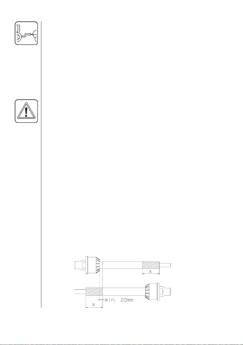
Installation of transmission shaft
Initial installation of the shaft is done as follows:
1. Attach sprayer to tractor and set sprayer in the position with short-
est distance between the tractor and sprayer pump P.T.O. shafts.
2. Stop engine and remove ignition key.
T259-0004
6
Page 9
3. If transmission shaft must be shortened, the shaft is pulled apart. Fit
the two shaft parts at tractor and sprayer pump and measure how
much it is necesary to shorten the shaft. Mark the protection guards.
T259-0004
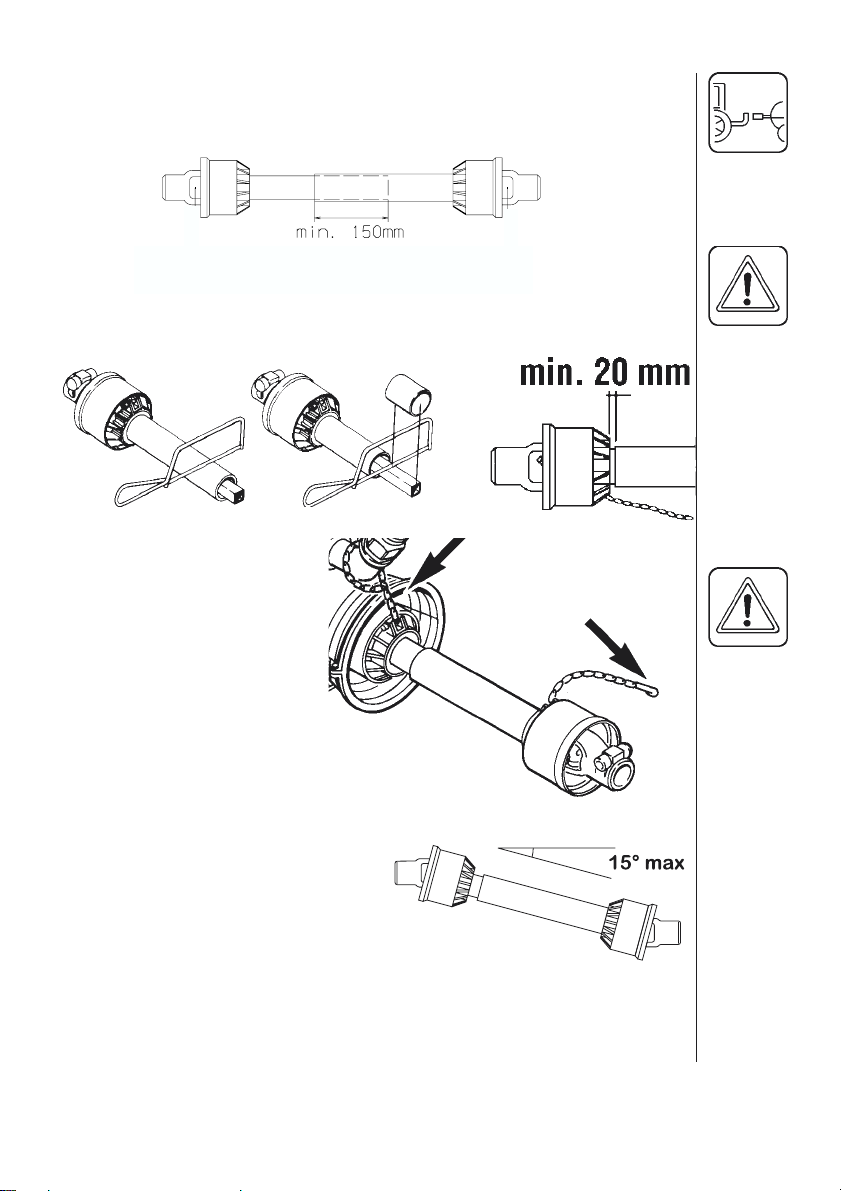
NOTE: The shaft must always have a minimum overlap 150 mm.
4. The two parts are shortened equally. Use a saw, and file the profiles
afterwards to remove burrs.
5. Grease the profiles, and assemble male and female parts again.
T259-0005
6. Fit the shaft to tractor
and sprayer pump.
NOTE: Female part
towards tractor.
Fit the chains to prevent
the protection guards to
rotate with the shaft.
7. To ensure long life of the
transmission shaft, try to
avoid working angles
greater than 15°.
8. Transmission shafts with
cone must be fitted by
tightening the Allen
screw to a torque of
40 Nm. Check again after
2 minutes use.
T259-0007
7
Page 10
Mechanical remote control - HR only
The operating unit remote control is fitted at a convenient place in the
tractor cabin.
Rear lights (if fitted)
Connect plug for rear lights to the tractors 7-poled socket and check
that rear lights, stop lights and direction indicators work properly before
driving anywhere.
The wiring is in ISO accordance. See section on Technical specifications.
Roadworthyness
When driving on public roads and other areas where the highway code
applies, or areas where there are special rules and regulations for
marking the lights on implements, you should observe these and equip
implements accordingly.
Operating instructions
Filling the tank
It is recommended to use as clean water as possible for spraying
purposes. Always fill water through the strainer basket to prevent
foreign particles from entering the tank. An overhead tank can be used
in order to obtain high filling capacity.
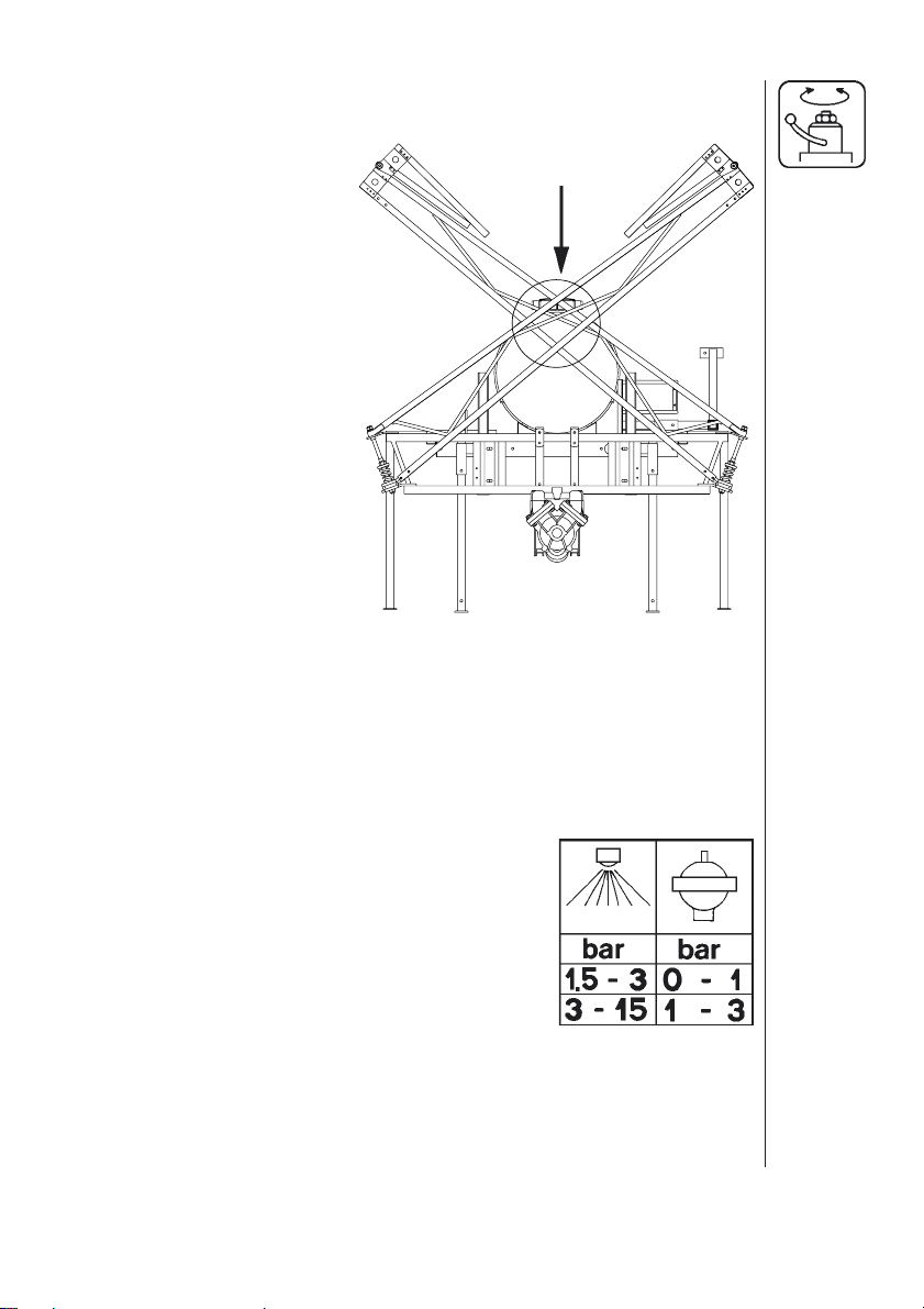
WARNING: Do not let the filling hose enter the tank. Keep it outside
the tank, pointing towards the filling hole.
If the hose is lead into the tank and the water pressure drops at the
water supply plant, chemicals may be syphoned back and contaminate
the water supply lines, plant and well.
8
Page 11
Unfolding and folding the boom
The boom is operated as follows:
1. Remove boom transport
lock pins A.
2. Swing the boom down.
When unfolding (or folding)
the initial force to release
the spring loaded breakaway will be higher than the
actual unfolding/folding.
CAUTION: The breakaway
must be correctly tensioned
and lubricated.
(See section on Re-adjustment of the boom).
3. Unfold the outer sections.
Do not let the outer sections fall into place.
4. Reverse procedure to fold.
A
Boom height
Correct boom height is very important in order to obtain optimum distribution of the liquid (see “Spray Technique” book).
The boom height can be manually adjusted by removing the 4 bolts
keeping the boom on the frame.
NOTE: This is best done by 2 persons or by means of a hoist.
Pulsation damper
The air pressure in the pulsation damper is factory preset at 2 bar to cover spray working pressures between 3 and 15 bar. When using spray
pressures outside this range, the air pressure
should be adjusted as shown in the diagram. The
diagram is also embossed on the damper.
9
Page 12
2
B
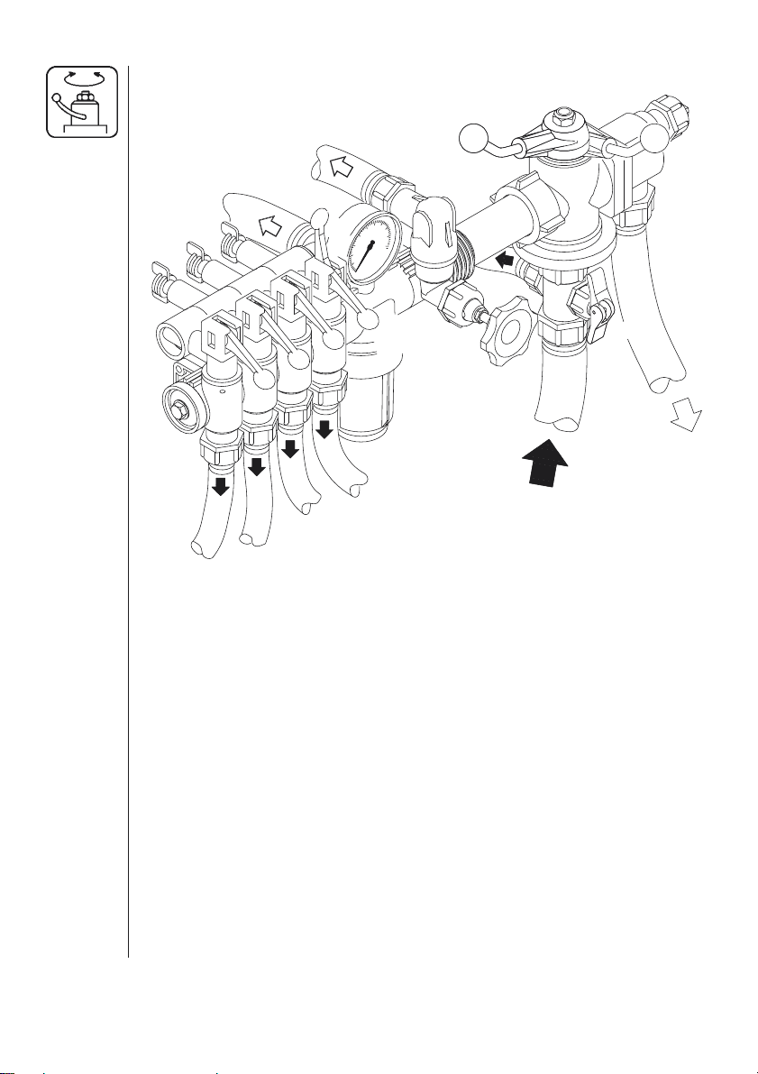
Adjustment of the BK controls
A
B
5
3
A
4
1
6
1. Choose the correct nozzle. Turn the TRIPLET nozzle bodies to the
suitable nozzle for the spray purpose. Make sure that all nozzles are
the same type and capacity. See “Spray Technique” book.
2. Open or close lever 1 depending on whether pressure agitation is
required. (Remember pressure agitation takes 5% to 10% of pump
output).
3. Turn main ON/OFF handle 2 to ON position A.
4. Set all hand levers 3 on the distribution valve to ON position A.
5. Turn the HARDI-MATIC valve 4 anti-clockwise to its extreme position.
6. Put the tractor in neutral and adjust the P.T.O. thereby the number
of revolutions of the pump corresponding to the intended travelling
speed.
NOTE: For units with 540 r/min P.T.O., the revolutions must be kept
between 300-600 r/min.
NOTE: For units with 1000 r/min P.T.O., the revolutions must be
kept between 800-1100 r/min.
7. Adjust the HARDI-MATIC valve 4 so that the pressure gauge indi-
cates the recommended pressure.
T020-0025
10
Page 13
ADJUSTMENT OF PRESSURE EQUALIZATION:
8. Place the first lever 3 on the distribution valve in OFF position B.
9. Turn the adjusting screw 5 until the pressure gauge again shows the
same pressure.
10.Adjust the other sections of the distribution valve in the same way.
Hereafter adjustment of pressure equalization will only be needed if
you change to nozzles of other capacities.
OPERATING THE CONTROL UNIT WHILE DRIVING:
11.To stop the liquid flow to the boom turn the ON/OFF handle 2 to
OFF position B. This returns the pump output to the tank through
the return system. The diaphragm anti-drip valves ensure instantaneous closing of all nozzles.
To stop the liquid flow to one or more boom sections, turn lever 3 of
the distribution valve to OFF position B for the section to be closed.
The pressure equalization ensures that the pressure does not rise in
the sections which are to remain open.
OPERATING THE EXTRA VALVE
12.A spray gun can be connected to the control unit. When using this
function, set hand levers 3 for the boom section to OFF position B.
Screw the adjusting screws 5 in to prevent liquid returing to the tank.
Set hand lever 6 to ON position A.
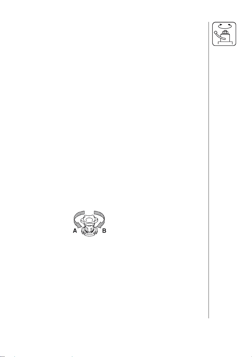
Operation of the tank drain valve (only 800 l tank)
To open: A
To close: B
Spray Technique - see separate book.
Optional Extras - see separate books.
11
Page 14

Maintenance
In order to derive full benefit from the sprayer for many years the following few but important rules should be kept:
Cleaning the sprayer
Guidelines
Read the whole label of the chemical. Take note of any particular
instructions regarding recommended protective clothing, deactivating
agents, etc. Read the detergent and deactivating agent labels. If cleaning procedures are given, follow them closely.
Be familiar with local legislation regarding disposal of pesticides
washings, mandatory decontamination methods, etc. Contact the
appropriate body, eg. Dept of Agriculture.
Pesticide washings can usually be sprayed out on a soakaway. This is
an area of ground that is not used for cropping. You must avoid seepage or run-off of residues into streams, water courses, ditches, wells,
springs, etc. The washings from the cleaning area must not enter
sewers. Drainage must lead to a soakaway.
Cleaning starts with the calibration, as a well calibrated sprayer will
ensure the minimal amount of remaining spray liquid.
It is good practice to clean the sprayer immediately after use thereby
rendering the sprayer safe and ready for the next pesticide application.
This also prolongs the life of the components.
12
It is sometimes necessary to leave spray liquid in the tank for short
periods, eg. overnight, or until the weather becomes suitable for spraying again. Unauthorized persons and animals must not have access to
the sprayer under these circumstances.
If the product applied is corrosive, it is recommended to coat all metal
parts of the sprayer before and after use with a suitable rust inhibitor.
Remember: Clean sprayers are safe sprayers.
Clean sprayers are ready for action.
Clean sprayers can not be damaged by pesticides and
their solvents.
Cleaning
1. Dilute remaining spray liquid in the tank with at least 10 parts water
and spray the liquid out in the field you have just sprayed.
Page 15

NOTE: It is advisable to increase the forward speed (double if possible) and reduce the pressure. For S4110 nozzles, pressure may
be reduced to 1.5 bar.
2. Select and use the appropriate protective clothing. Select detergent
suitable for cleaning and suitable deactivating agents if necessary.
3. Rinse and clean sprayer and tractor externally. Use detergent if
necessary.
4. Remove tank and suction filters and clean. Be careful not to damage
the mesh. Replace suction filter top. Replace filters when the
sprayer is completely clean.
5. With the pump running, rinse the inside of the tank. Remember the
tank roof. Rinse and operate all components and any equipment
that has been in contact with the chemical. Before opening the
distribution valves and spraying the liquid out, decide whether this
should be done in the field again or on the soakaway.
6. After spraying the liquid out, stop the pump and fill at least 1/5 of the
tank with clean water. Note that some chemicals require the tank to
be completely filled. Add appropriate detergent and/or deactivating
agent, eg. Washing soda or Triple ammonia.
NOTE: If a cleaning procedure is given on the chemical label, follow
it closely.
7. Start the pump and operate all controls enabling the liquid to come
in contact with all the components. Leave the distribution valves
until last. Some detergents and deactivating agents work best if left
in the tank for a short period. Check the label.
If fitted the Self-Cleaning Filter can be flushed by removing the
bypass hose from the bottom of the filter. Stop the pump and remove the hose. Start the pump for a few seconds to flush filter. Be
careful not to loose the restrictor nozzle.
8. Drain the tank and let pump run dry. Rinse inside of tank, again
letting the pump run dry.
9. Stop the pump. If the pesticides used have a tendency to block
nozzles and filters, remove and clean them now. Check also for
sediment on the pressure side of the safety valve for the Self-Cleaning Filter.
10. Replace all the filters and nozzles and store the sprayer. If, from
previous experiences, it is noted that the solvents in the pesticide
are particularly aggressive, store the sprayer with the tank lid open.
NOTE: If the sprayer is cleaned with a high pressure cleaner we
recommend lubrication of the entire machine.
13
Page 16

Filters
Clean filters ensure :
• Sprayer components such as valves, diaphragms and operating unit
are not hindered or damaged during operation.
• Nozzle blockages do not occur whilst spraying.
• Long life of pump. A blocked suction filter will result in pump cavitation.
Suction filter
The main filter protecting sprayer components is the suction filter.
Check it regularly.
The BS 300 sprayer has a suction filter placed in the bottom of the tank.
The BS/HR 800 has a suction filter placed in the top of the tank.
BK Pressure filter / In Line Filters (if fitted)
The BK operating unit has an in-built pressure filter. Unscrew the filter
bowl to inspect and clean the filter.
The boom may be equipped with In Line Filters. Unscrew the filter bowl
to inspect and clean the filter.
Alternative filters are available. See section on Technical specifications
- Filters and nozzles.
14
Page 17
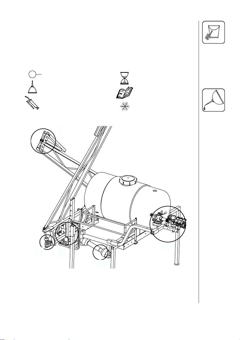
Lubrication
Recommended lubrication is shown in following table. Use ball bearing
grease (lithium grease No. 2).
Note: If the sprayers are cleaned with a high pressure cleaner or fertilizer has been used, we recommend lubrication of all sections and all
metal parts by means of corrosion protective oil.
5
Position on sprayer
Operation hours
4
Oil
Grease
5
1
Page to find more
information
Winter protection/
off-season storage
3
2
15
Page 18
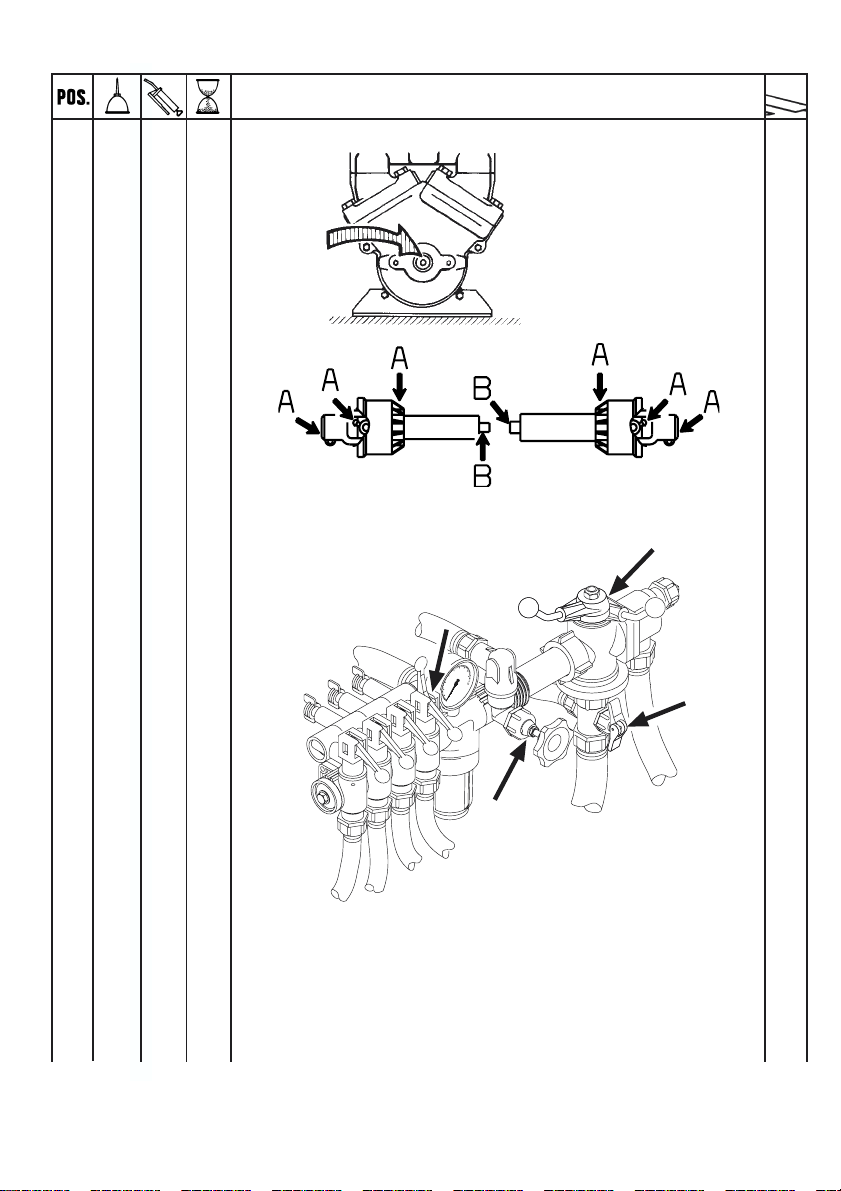
1X40
2
AX8
AX40
3X 40
17
6
9
16
T200-0001
Page 19

4X40
5X 40
HR only
X
1000
or once a year
16
16
17
Page 20

Re-adjustment of the boom
After having used the sprayer for some days the boom should be
adjusted according to the following instructions:
Carry adjustments out in the following order.
NOTE: Tractor and sprayer must be on level ground.
Sprayer must be lubricated. See section on Lubrication.
Boom breakaway
The function of the breakaway is
to prevent or reduce boom damage if it should strike an object or
the ground. If it is too tight, it will
not function. If it is too loose, it will
yaw (forward and back movement).
Slacken screw nut A to decrease
breakaway resistance. Do not
tighten excessively; better too
loose than too tight. Again minor
adjustments in the field may be
necessary.
Ensure also channel bolts B are
tight.
C
18
Outer section (8 and 10 m only)
The hinge should be firm. If too
tight it is difficult to fold. To adjust, tighten or loosen nuts C.
Recommended tyre pressure (only HR)
The tyres should not run under-inflated. This only promotes instability
and rapid wear.
Tyre size : 26" x 12"
Pressure :1.6 bar (24 p.s.i.)
The pressure is specified for a full loaded trailer.
Remember it is easier to let off a little pressure for a specific use than
to re-inflate a tyre in mid-field.
Page 21

Wheel nuts and bearings (only HR)
Check wheel nut tension after the first 8 working hours, hereafter every
50 hours.
Check roller bearing slack after the first 8 hours and 50 hours.
Thereafter every 100 hours.
If necessary, adjust as follows
1. Jack wheel up. It is best to remove the wheel.
2. Remove hub cap A and split pin B.
3. Shaft nut C is tightened until slight
rotation resistance of drum is noted.
4. Now loosen shaft nut until first split
pin hole is visible.
5. Insert split pin and replace hub cap.
After 1000 hours or once a year, the
axle bearings are greased.
Changing of valves and diaphragms
Valves
Remove valve cover 1. Before changing the valves 2 note their orientation so they are replaced correctly.
It is recommended to use new gaskets 3 when changing or checking
the valves.
19
Page 22

Diaphragms
Remove the diaphragm cover 4. The diaphragm 5 may then be
changed. If fluids have reached the crankcase, re-grease the pump
thoroughly. Check also the drain hole at the bottom of the pump is not
blocked. Reassemble with the following torque setting.
Pump Valve cover Diaphragm Diaphragm
Model Nm cover Nm bolt Nm
1302 45 50 25
1202 70 70 60
1 Nm = 0.74 ft-lb
Changing the ball seat in operating unit
If the main ON/OFF valve does not seal properly
(dripping nozzles when main ON/OFF valve
is closed), the ball and seat should
be checked.
Remove the 2 bolts fixing
the main ON/OFF-pressure valve unit to the
bracket, unscrew the
union nut A and pull the
valve away from the distribution valves.
Check the ball for sharp edges and scratches, and check the ball seat
for cracks and wear - replace if necessary.
A
Nozzle tubes and fittings
Poor seals are usually caused by;
• missing O-rings or gaskets
• damaged or incorrectly seated O-rings
• dry or deformed O-rings or gaskets
• foreign bodies
T199-0001
20
Page 23

Therefore, in case of leaks: DO NOT overtighten. Disassemble, check
condition and position of O-ring or gasket, clean lubricate and reassemble. The O-ring should be lubricated ALL THE WAY ROUND
before fitting on to the nozzle tube.
For radial connections only hand tighten.
For axial connections, a little me-
chanical leverage may be used.
T199-0002
Off-season storage
When the spraying season is over you should devote some extra time
to the sprayer before it is stored.
Hoses
Check that none of the hoses are cut or have sharp bends.
A leaky hose can give an annoying delay in the middle of the spraying
job. Therefore check all the hoses and replace them if there is any
doubt about the durability.
Paint
Some chemicals are very rough on paints. It is therefore well advised
to remove rust, if any, and then touch up the paint.
Tank
Check that no chemical residues are left from the last spraying. Chemical residues must not be left in the tank for a long time. It will reduce
the life of the tank. See section on Cleaning the sprayer.
Transmission shaft
Check that the shaft fullfils its security purpose, e.g. that shields and
protective tubes are intact.
Anti-freeze precaution
If the sprayer is not stored in a frost free place you should take the
following precautions: Put at least 10 litres of 33% anti-freeze mixture
in the tank and let the pump run a few minutes so that the entire system including spray hose are filled. The anti-freeze solution also hinders the O-rings and gaskets from drying out.
Remove the glycerine filled pressure gauge and store it frost free in
vertical position.
21
Page 24

Operational problems
In cases where breakdowns have occurred the same factors always
seem to come into play:
• Minor leaks on the suction side of the pump will reduce the pump
capacity or stop the suction completely.
• A clogged suction filter will hinder or prevent suction so that the
pump does not operate satisfactorily.
• Clogged up pressure filters will result in increasing pressure at the
pressure gauge but lower pressure at the nozzles.
• Foreign bodies stuck in the pump valves with the result that these
cannot close tightly against the valve seat. This reduces pump
efficiency.
• Poorly reassembled pumps, especially diaphragm covers will allow
the pump to suck air resulting in reduced or no capacity.
Therefore ALWAYS check
1. That suction, pressure and nozzle filters are clean.
2. Hoses for leaks and cracks, paying particular attention to suction
hoses.
3. Gaskets and O-rings are present and in good condition.
4. Pressure gauge is in good working order. Correct dosage depends
on it.
5. Operating unit functions properly. Use clean water to check.
22
Fault Probable cause Control / remedy
Liquid system
No spray from
boom when
turned on.
Air leak on suction.
Air in system.
Suction/pressure
filters clogged.
Check if red suction lid/O-ring are
sealing.
Check suction tube and fittings.
Check tightness of pump diaphragm
and valve covers.
Fill suction hose with water for initial
prime.
Clean filters.
Check yellow suction pipe is not
obstructed or placed too near the
tank bottom (only 800 l tank).
Page 25

Fault Probable cause Control / remedy
Lack of
pressure.
Pressure
dropping.
Pressure
increasing
Formation of
foam.
Incorrect assembly.
Pump valves blocked
or worn.
Defect pressure
gauge.
Filters clogging.
Nozzles worn.
Tank is airtight.
Sucking air towards
end of tank load.
Pressure filters
beginging to clog.
Agitation nozzles
clogged.
Air is being sucked
into system.
Excessive liquid
agitation.
Agitation nozzles not fitted.
Too little distance between yellow
suction pipe and tank bottom (only
800 l tank).
Check for obstructions and wear.
Check for dirt at inlet of gauge.
Clean all filters. Fill with cleaner
water.
If using powders, make sure
agitation is on.
Check flow rate and replace nozzles
if it exceeds 10%.
Check vent is clear.
Exessive agitation, turn off.
Returns inside tank need relocation.
Clean all filters.
Check by turning agitation off/on.
Check tightness / gaskets / O-rings
of all fittings on suction side.
Turn agitation off.
Reduce pump r/min.
Ensure returns inside tank are
present.
Liquid leaks
from bottom of
pump.
Damaged diaphragm.
Use foam damping addative.
Replace. See Changing of valves
and diaghragms.
23
Page 26

Technical specifications
Measure and weight
AB
C
C
24
AB
Model Boom width Pressure Dimension
BS 300 6 SB 15 265 x 195 x 192/225
BS 300 8 SB 15 265 x 195 x 237/270
HR 800 6 SB 15 310/350 x 195 x 180/230
HR 800 8 SB 15 310/350 x 195 x 225/275
m max. bar A x B x C
Weight:
BS 300: from 172 - 213.5 kg depending on model
BS 800: from 234 - 256 kg depending on model
Page 27

Pump power consumption and capacity
1202/6.0
bar l/min kW l/min kW l/min kW l/min kW l/min kW
0 46 58 72 95 112
531 39 47 62 77
10 30 37 44 59 73
15 28 35 42 55 69
Rotation per min. r/min Capacity l/min Suction height 0,0 m
Power consumption kW Max. pressure 15 bar Weight 24,0 kg
1202/9.0
bar l/min kW l/min kW l/min kW l/min kW l/min kW
0 56 0,91 72 1,28 93 1,52 99 1,63 112 1,79
5 40 1,11 53 1,36 66 1,60 71 1,71 79 1,86
10 38 1,38 52 1,74 64 1,79 69 1,87 77 2,07
15 37 1,60 50 1,97 62 2,32 67 2,48 75 2,76
Rotation per min. r/min Capacity l/min Suction height 0,0 m
Power consumption kW Max. pressure 15 bar Weight 24,0 kg
1302/9.0
bar l/min kW l/min kW l/min kW l/min kW l/min kW
0 63 0,90 84 1,19 103 1,51 114 1,61 125 1,80
5 58 0,94 79 1,29 96 1,61 105 1,75 116 1,93
10 56 1,30 76 1,80 94 2,30 101 2,48 111 2,72
15 55 1,80 74 2,22 93 2,92 99 3,18 109 3,54
Rotation per min. r/min Capacity l/min Suction height 0,0 m
Power consumption kW Max. pressure 15 bar Weight 35,0 kg
400 500 600 800 1000
300 400 500 540 600
300 400 500 540 600
r/min
r/min
r/min
Rear lights connection diagram
Position Wire colour
1. LH direction indicator Yellow
2. Free Blue
3. Frame White
4. RH direction indicator Green
5. RH rear position lamp Brown
6. Stop lamps Red
7. LH rear position lamp Black
1
6
5
2
7
3
4
25
Page 28

Filters and nozzles
30 mesh suction filter
(only BS/HR 800)
50 mesh operating
unit/pressure filter
Mesh 30 50 80 100
GBRY
0.58 0.30 0.18 0.15
G= Green B= Blue R= Red Y= Yellow
50 mesh nozzle filters
Temperature and pressure ranges
Operating temperature range : 2° to 40° C.
Operating pressure for safety valve : 15 bar
Materials and recycling
Tank HDPE
Hoses PVC
Fittings PA
Disposal of the sprayer
When the equipment has completed its working life, it must be thoroughly cleaned. The tank, hose and synthetic fittings can be incinerated at an authorized disposal plant. The metallic parts can be
scrapped. Always follow local legislation regarding disposal.
26
Pictorial symbols
Description
Function
Connection
Warning
Operating
Service/adjustment
Liquid flow
Pressure
Cleaning
Lubrication
Winter
storage
Operational
problems
Technical specifications
EC Declaration
of Conformity
Page 29

Assembly
Preassembly information
The sprayer is supplied ex-works in shipping packages (SP). Number
of SP’s per sprayer varies depending on model.
As this covers all BS/HR models, please note the fittings covering
exactly your model.
NOTE: Removal of the plastic bag covering the tank is easiest done
before assembly.
Some components are shipped within the tank. Check inside.
To verify connection of hoses, a function diagram is included on the
last page.
Packaging information
Materials used for packaging are environmentally compatible. They
can be safely deposited or they can be burnt in an incinerator.
Recycling
Cardboard: Can recycle up to 99% and therefore should be put into
the waste collection system.
Polystyrene foam: Can be recycled. Fluorocarbons (CFC) not used in
foam production. Polyethylene: Can be recycled.
NOTE: Use O-rings where indicated. Lubricate them with non-mineral
lubricant (silicon oil) before assembly. Where O-rings are not indicated,
use sealing tape.
Check that all shipping packages are present.
T159-0001
27
Page 30

BS 300 sprayer
1. Fit rear brackets for support legs.
The 4 legs to be mounted in
brackets and platform. Use crane
or be 2 persons for the job. Lock
with split bolts for your safety.
T142-0016
28
2. Remove plastic protection
from the tank. Use profile
strips before the tank is
placed in its frame. Strips
and tank are fixed with
tank straps. Remember
the socket in one end of
the tank must point forward.
T142-0019
Page 31

3. Fit straight bracket in right hand side of
platform and then S-shaped bracket and
operating unit arm.
4. Main ON/OFF handle
1B is closed. Put ball
into the handle and
turn it to working
position 1A, whereby
the ball disappears
into the operating unit.
Fit ball seat on distribution valves which
are tightened to the
main ON/OFF part. Fit
the operating unit with
snap screws and
plastic nuts.
T140-0023
T140-0022
29
Page 32

5. Screw pressure gauge on with teflon
tape to filter body . Do not overtighten.
See back of gauge. Remember to
pierce casing after installation.
6. Fit angle bracket
to frame and fit
central section to
angle bracket.
Clamp and nozzle
screen are placed
on central section.
Mount 6 m SB
outer section or
8 m SB intermediate/outer
sections.
Be careful when
folding the boom
for the first time
(see section on
Re-adjustment
of the boom).
T140-0005
30
T153-0004
Page 33

8m SB
T153-0005
6m SB
M10x65
7. Tighten transport bracket
of sprayer boom:
6 m SB: First fold right outer
section - fit lock.
8 m SB: Fit transport bracket on
central section.
8. Use sealing tape on pump suction
and pressure fittings. Mount pulsation dampers (O-ring diameter
30/26x2).Fit bottom half of the
yellow protection guard. Lubricate
conical shaft, connect the transmission shaft and fit upper part of
guard. Recheck the grub screw
is tight after 5 min. of usage.
A. Suction from tank
B. Pressure to operating
unit
T153-0006
T141-0008
31
Page 34

9. For model 1202 pump, use pump socket with reinforcement which
must be placed outward. Tighten pump socket to central section.
Fix the chain of the transmission shaft to prevent the protection
tubes from rotating.
T141-0006
10.Nozzle tubes are
supplied with one
lock nozzle saddle per tube A.
The rest can slide
lengthwise B
allowing for extension and
contraction.
32
A
B
T145-0010
Page 35

11.Tubes and hoses are connected. Fit tubes using synthetic nut.
Press down (1), turn (2). Do not over-tighten. Fit filter and COLOR TIPS.
REMEMBER: Lubricate O-rings before fitting.
8m SB
6m SB
8m SB
T145-0012
T145-0011
T145-0013
12.Adjust mounting
bracket of tank
frame to your tractor.
Connect the sprayer.
Shorten, if necessary, the transmission shaft.
Adjust operating
unit bracket.
T145-0009
33
Page 36

A. Suction hose of pump
B. Pressure hose of pump
C.By-pass to main ON/OFF valve
H.By-pass to HARDI-MATIC
E. By-pass for pressure equalization
valves
F. Feed hoses for boom
Secure hoses with plastic straps.
Check they do not foul. Shorten
if necessary.
Test the sprayer with clean water
and check for leaks. Tighten if
necessary.
T145-0008
34
T142-0017
Page 37

BS 800 sprayer
1. Fit front and
rear support legs
to mainframe. Use
crane or be 2 persons for
the job.
Lock with split bolts for your safty.
2. Tighten bracket and hole profile
together with the tank frame and
mainframe.
3. Fit footboard on the right side of
mainframe.
T142-0018
T142-0006
35
Page 38

4. Fit bracket to the right
front support, then fold
away mechanism and
operating unit arm.
(If equiped fit Foam
marker bracket).
5. Fit angle brackets to frame and
central section to angle brackets. Fit clamp and nozzle
screen to central section. Mount
intermidiate/outer
sections.
Be careful when
folding the boom
for the first time.
(See section
on readjustment of the
boom).
T142-0007
36
T153-0001
Page 39

6. Tighten boom
transport bracket.
M10x65
First fold right hand
intermidiate/outer
sections.
Fit lock.
7. 10 m SB ONLY: Fit
outer section locks.
T153-0006
8. See BS 300 point 8
9. Fit pump bracket to central section.
Note: The reinforcement must be
placed outward. Fix the chain of
the transmission shaft to prevent
the protection tubes from rotating.
10m SB
T153-0007
T141-0006
37
Page 40

10. See BS 300 punkt 10 and 11
11. Close main ON/OFF
handle (1B) on the
operating unit. Put the
ball into the handle
and turn it to working
position, Whereby the
ball dissapears into the
operating unit. Fit ball
seat on distribution
valves which are tightened to the main ON/
OFF. part. Use screws
and plastic nuts to fit
the operating unit.
T140-0007
12. Use sealing tape
on the pressure
gauge. See back
of pressure gauge.
Pierce casing and
fit gauge.
Do not tighten
by twisting the
gauge casing use spanner. Do
not overtighten.
38
T140-0022
T140-0005
Page 41

13. Fit hoses to operating unit and tank.
A Pump suction hose.
B Pump pressure hose.
C By-pass to main ON/OFF handle.
D Pressure agitation.
E By-pass to pressure equalization.
F Feed hoses to boom
H By-pass to HARDI MATIC
Secure hoses with plastic straps.
Check that hoses do not foul in spraying or transport position.
T142-0020
39
Page 42

14. Fit mounting bracket to frame
of vehicle. Connect sprayer to
vehicle. Shorten if necessary,
the transmission shaft. See
instruction book on connecting the sprayer.
15. The sprayer is tested with water at high pressure in order to reveal possible
leakages. Leakages must be sealed.
Optional extras:
16. Bracket for hose
reel is fitted on
the left side of
the rear tankframe support.
T142-0007
40
T164-0004
Page 43

17. The HARDI FILLER is fitted on the left side of the mainframe.
T164-0005
18. Bracket for 15L
clean water tank
is to be fitted on
the left side of the
front tankframe
support.
T164-0006
41
Page 44

19.Bracket for Foammarker tanks is to
be fitted on the right
side of the rear
tankframe support.
T164-0007
20. HARDI® Nozzle
Booklet.The self
cleaning filter is
fitted to the
operating unit
arm using the ushaped clamp.
42
T164-0008
Page 45

HR 800 sprayer
1. Fit wheels and nose wheel on
frame. Fit hole profile 40 x 40 mm
(length 2.2 m) on frame with
U-bracket. Place rear A
and front B
trestles and
then pump
bracket C.
2. Tighten bracket and hole profile D together
with tank frame and trestle. The position of
tank/trestles can be changed according to
wish - tighten U-brackets E on frame.
C
43
Page 46

3. See BS 800 point 6.
4. See BS 800 point 7 and 8.
5. Place tubes and hoses. Do not forget to lubricate. Fit tubes with synthetic
nut. Press 1 down and turn 2. Do not overtighten. Fit filter and COLOR TIPS.
10m SB
8m SB
T145-0012
6. See BS 300 point 8.
7. See BS 800 point 12,13 and 14.
T145-0011
6m SB
T145-0013
44
Page 47

1202/foot A10
45
Page 48

A12 1302/foot47Unit BK 180K (92) B9
46
Page 49

Page 50

B10 Distributor BK180K (92)
48
Page 51

Damper HJ73 B300
49
Page 52

D2 SB 6/8/10 m
50
Page 53

Boom tube TRIPLET SNAP-FIT D904
51
Page 54

H106 PS 300
52
Page 55

TPS 800 H107
53
Page 56

H108 PU/TPS 80055Shaft (94) K604
54
Page 57

HELGESHØJ ALLÉ 38 • DK 2630 TAASTRUP • DENMARK
HARDI INTERNATIONAL A/
0396
EN 1152 / ISO 5674
POS.
AX 8
BX 40
rpm kW Nm
540 12 210
1000 18 172
S
HARDI
978389
Page 58

56
Page 59

Spare parts
To see updated spare part information the website
www.agroparts.com can be visited. Here all parts
information can be accessed when free registration
has been made.
Page 60

HARDI INTERNATIONAL A/S
Helgeshøj Allé 38 - DK 2630 Taastrup - DENMARK
 Loading...