

Page 1

The Sprayer
Operator’s Manual
CONTROLLER
HC 8600/9600
Instruction book - SW 1.X
67025303 - Version 1.00
US - 03.2017
Page 2

Page 3

CONTROLLER
HC 8600/9600
Instruction book - SW 1.X
67025303 - Version 1.00
US - 03.2017
HARDI® reserves the right to make changes in design, material, or specification without notice thereof.
HARDI® and other product names are registered trademarks of HARDI® Inc. in the U.S. and in other countries.
Page 4

Page 5

Table of Contents
Table of Contents
1 - Welcome
Welcome letter ......................................................................................................................................7
HC 8600 and HC 9600 .............................................................................................................................8
About this Instruction Book ............................................................................................................................................................................. 8
Differences between the Controllers ........................................................................................................................................................8
2 - Safety Notes
Operator Safety .....................................................................................................................................9
Symbols ........................................................................................................................................................................................................................ 9
Precautions ................................................................................................................................................................................................................ 9
3 - Description
Display .................................................................................................................................................11
General info ............................................................................................................................................................................................................ 11
System Uses ............................................................................................................................................................................................................ 11
System Features ................................................................................................................................................................................................... 11
Display Hardware ................................................................................................................................................................................................ 12
USB Flash Drive ..................................................................................................................................................................................................... 13
ISOBUS Technology ........................................................................................................................................................................................... 13
Color Touch Screen ........................................................................................................................................................................................... 13
Gestures .................................................................................................................................................................................................................... 14
Screen Icon Conventions ............................................................................................................................................................................... 15
Initial Start-up .....................................................................................................................................16
General info ............................................................................................................................................................................................................ 16
Initial Setup Wizard ............................................................................................................................................................................................ 16
Home Screen Layout ........................................................................................................................................................................................ 17
Status Indicators .................................................................................................................................................................................................. 18
Map Screen ..........................................................................................................................................19
Work Screen ........................................................................................................................................................................................................... 19
Map Toolbox ........................................................................................................................................22
Legend Settings ................................................................................................................................................................................................... 22
Map Options .......................................................................................................................................................................................................... 23
Map Shift .................................................................................................................................................................................................................. 24
Split-Screen Map ................................................................................................................................................................................................. 26
Markers tab .............................................................................................................................................................................................................. 27
Video ........................................................................................................................................................................................................................... 27
AgFiniti ................................................................................................................................................28
General Info ............................................................................................................................................................................................................ 28
AgFiniti Mobile Connection Types ........................................................................................................................................................... 28
Miscellaneous ......................................................................................................................................29
About AutoTerrain/AutoHeight ................................................................................................................................................................. 29
Glossary of Application Settings ................................................................................................................................................................ 29
4 - System setup
Installation ..........................................................................................................................................31
Installation Instructions ................................................................................................................................................................................... 31
Cable connections ............................................................................................................................................................................................. 32
Initial Start-up .....................................................................................................................................35
General info ............................................................................................................................................................................................................ 35
Advanced Options ............................................................................................................................................................................................. 35
Location Specific Setup ................................................................................................................................................................................... 36
Single Display ........................................................................................................................................................................................................ 37
Multiple Displays ................................................................................................................................................................................................. 39
Import Setup Data .............................................................................................................................................................................................. 43
Home Screen ......................................................................................................................................................................................................... 44
Universal Terminal ..............................................................................................................................45
Universal Terminal together with HC 8600/HC 9600 ................................................................................................................... 45
General info about Universal Terminal .................................................................................................................................................. 45
Enable Universal Terminal and Task Controller ................................................................................................................................ 45
3
Page 6

Table of Contents
Quick Setup Guide ...............................................................................................................................48
General Info ............................................................................................................................................................................................................ 48
Before Setup ........................................................................................................................................................................................................... 48
Configuration for Trailer and Lift sprayers ........................................................................................................................................... 48
Configuration for Self-Propelled sprayers ............................................................................................................................................ 60
Product setup ........................................................................................................................................................................................................ 68
Configuration ......................................................................................................................................71
Setup buttons ....................................................................................................................................................................................................... 71
Equipment Setup ................................................................................................................................................................................................ 72
Management button ........................................................................................................................................................................................ 74
Edit User Profile .................................................................................................................................................................................................... 78
Permissions tab .................................................................................................................................................................................................... 78
Permission Level for Operators .................................................................................................................................................................. 79
Accessing Setup Menus .................................................................................................................................................................................. 81
Accessing Data Transfer .................................................................................................................................................................................. 82
Forgotten Passwords ........................................................................................................................................................................................ 83
Display Button ....................................................................................................................................................................................................... 84
Settings ................................................................................................................................................89
Speed Input Settings ........................................................................................................................................................................................ 89
Automatic Swath Control (AutoSectionControl) ............................................................................................................................ 90
Vehicle Offsets ....................................................................................................................................................................................................... 91
GPS Guidance/Steering Control ..........................................................................................................93
Setup ........................................................................................................................................................................................................................... 93
WAAS/EGNOS Settings .................................................................................................................................................................................... 95
TerraStar Settings ................................................................................................................................................................................................ 95
RTK External Settings ........................................................................................................................................................................................ 96
RTK Settings - NTRIP .......................................................................................................................................................................................... 96
RTK Settings - 400 MHz .................................................................................................................................................................................... 98
RTK Settings - 900 MHz .................................................................................................................................................................................... 98
Upgrade Receiver ............................................................................................................................................................................................... 99
Serial Port Settings .............................................................................................................................................................................................. 99
Lightbar Settings .............................................................................................................................. 101
Setup .........................................................................................................................................................................................................................101
Guidance Tab on Mapping Toolbox .....................................................................................................................................................101
New Pattern - Straight ....................................................................................................................................................................................102
New Pattern - Adaptive Curve ..................................................................................................................................................................103
New Pattern - Identical Curve ...................................................................................................................................................................104
New Pattern - Pivot ..........................................................................................................................................................................................105
New Pattern - SmartPath ..............................................................................................................................................................................107
AutoSave ................................................................................................................................................................................................................110
Manage Patterns ...............................................................................................................................................................................................110
Pattern Groups ....................................................................................................................................................................................................111
Guidance Options .............................................................................................................................................................................................113
Liquid Rate Control ........................................................................................................................... 118
Creating Products .............................................................................................................................................................................................118
Creating Single Products ..............................................................................................................................................................................118
Creating Product Templates ......................................................................................................................................................................118
Configure Product Mix ...................................................................................................................................................................................120
Create Configuration ......................................................................................................................................................................................122
Load Configuration ............................................................................................................
Implement Offsets ............................................................................................................................................................................................122
Equipment Settings .........................................................................................................................................................................................123
Configuration Setup ........................................................................................................................................................................................124
Rate Control: Product Control Toolbox ...............................................................................................................................................125
Loading Prescriptions .....................................................................................................................................................................................129
Shape File Conversion ...................................................................................................................................................................................130
..............................................................................122
4
Page 7

Table of Contents
AgFiniti ............................................................................................................................................. 132
Display Access Point connection type ................................................................................................................................................132
AgFiniti Mobile ...................................................................................................................................................................................................135
Filters .........................................................................................................................................................................................................................136
Stat Cards ...............................................................................................................................................................................................................136
Zoom Options .....................................................................................................................................................................................................138
Summary Reports .............................................................................................................................................................................................138
Menu button ........................................................................................................................................................................................................139
AgFiniti Display Settings ...............................................................................................................................................................................140
Logging into an AgFiniti Account ..........................................................................................................................................................140
Logout and De-register Display ...............................................................................................................................................................140
Mobile Management ......................................................................................................................................................................................140
File Transfer ...........................................................................................................................................................................................................140
Remote Support ................................................................................................................................................................................................141
Remote Support Pre-authorization .......................................................................................................................................................141
Remote Support Permissions Options ................................................................................................................................................141
Cellular iPad as Personal Hotspot Connection ...............................................................................................................................142
Shared Wi-Fi Network Connection ........................................................................................................................................................145
Data Management ............................................................................................................................ 148
Data Transfer screen ........................................................................................................................................................................................148
Display Backups .................................................................................................................................................................................................148
Upgrade Firmware ...........................................................................................................................................................................................149
Importing Logged Data ................................................................................................................................................................................149
Exporting Logged Data .................................................................................................................................................................................150
Manual Sync .........................................................................................................................................................................................................150
5 - Operation
Map Screen ....................................................................................................................................... 151
Configuration Setup Screen .......................................................................................................................................................................151
Mapping Toolbox .............................................................................................................................................................................................151
Boundary ................................................................................................................................................................................................................153
Field Operations ............................................................................................................................... 155
Operator Selection ...........................................................................................................................................................................................155
Operator Log Out ..............................................................................................................................................................................................155
Menu Buttons ......................................................................................................................................................................................................155
Events .......................................................................................................................................................................................................................156
Setup Event ...........................................................................................................................................................................................................156
GPS Button ............................................................................................................................................................................................................159
Work Screen Operations ...............................................................................................................................................................................160
Heading Change Button ..............................................................................................................................................................................160
Rate Control Settings ......................................................................................................................................................................................161
Display Item Selection ...................................................................................................................................................................................162
Boom Height Control Options ..................................................................................................................................................................162
Headlands ..............................................................................................................................................................................................................163
Topography ..........................................................................................................................................................................................................167
Finalize Event .......................................................................................................................................................................................................170
Reports ............................................................................................................................................. 171
Summary Report ................................................................................................................................................................................................171
Event Summary ..................................................................................................................................................................................................173
Smart Reports™ (HC 9600 only) ................................................................................................................................................................175
6 - Maintenance
General info ...................................................................................................................................... 181
Service ......................................................................................................................................................................................................................181
Fuse Installation and Replacement ........................................................................................................................................................181
System and Upgrades ....................................................................................................................................................................................181
5
Page 8

Table of Contents
7 - Fault finding
Devices ............................................................................................................................................. 183
CAN Diagnostics ................................................................................................................................................................................................183
ISOBUS .............................................................................................................................................. 185
ISOBUS Universal Terminal ..........................................................................................................................................................................185
UT Alarms and Trouble Codes ..................................................................................................................................................................186
ISOBUS Modules ............................................................................................................................... 187
Modules not found ..........................................................................................................................................................................................187
ISOBUS Configuration Mismatch ............................................................................................................................................................188
GPS ................................................................................................................................................... 189
GPS Information .................................................................................................................................................................................................189
GPS Information - General Tab .................................................................................................................................................................189
GPS Messages ......................................................................................................................................................................................................191
Satellite Plot ..........................................................................................................................................................................................................192
GPS Information .................................................................................................................................................................................................193
8 - Technical specifications
Specifications ................................................................................................................................... 197
Technical Specifications ................................................................................................................................................................................197
Sprayer Offsets ....................................................................................................................................................................................................197
Appendix .......................................................................................................................................... 198
Current File Formats ........................................................................................................................................................................................198
Legacy File Formats .........................................................................................................................................................................................198
12 - Warranty
Warranty policy and conditions ....................................................................................................... 201
Index
Index ................................................................................................................................................. 203
6
Page 9

1 - Welcome
Welcome letter
Dear New HARDI® Owner,
Thank you for purchasing your new HARDI® product and welcome to the ever-increasing family of proud HARDI® owners.
HARDI® is the leading sprayer company in offering growers strong, reliable products made for the widest range of
applications worldwide. Quality, reliability, and resale value make the HARDI® product line the preferred product line of
customers both in North America as well as worldwide. Our guiding principle is to provide the highest level of customer
satisfaction and long term value in the marketplace today. We have developed a very high level of customer loyalty in the
marketplace which we are very proud of and strive every day to maintain and to continue to grow.
HARDI® is your specialist in spraying and we spend all of our time and keep all of our focus on spraying. We do not share our
resources between other types of products or compromise on anything in providing the best quality sprayers to the market
today. We can provide the latest in technology with our products if desired, or allow them to operate with the technology
that you already use on other products in most cases. You get to decide that, and what best suits your needs. We feel that
you, our customer, are the best suited to answer that question for your operation. Either way, you decide, and we will try and
help make it happen for you.
Our broad spectrum of product offerings, from the ruggedly simple models we build to our highly sophisticated models,
the built-in HARDI® strength and reliability ensures a low cost of ownership. HARDI® sprayers are all based on a functional
design concept of being as simple to operate as possible and to meet our customers’ requirements for all their application
needs.
Please take the time to thoroughly read the Operator’s Manual before using your equipment. You will find many helpful hints
as well as important safety and operation information.
Some of the features on your HARDI® sprayer were suggested by growers. There is no substitute for “on farm” experience
and we invite your comments and suggestions. If any portion of this instruction book remains unclear after reading it,
contact your HARDI® dealer or service personnel for further explanation before using the equipment.
For Product, Service or Warranty Information please contact your local HARDI® dealer.
- Please use the HARDI® Customer Service number: 1-866-770-7063
- Or send your email to CUSTSERV@hardi-us.com
HARDI® NORTH AMERICA INC.
Visit us online at: www.hardi-us.com
1500 West 76th St.
Davenport, Iowa 52806
Phone: (563) 386-1730
Fax: (563) 386-1280
Sincerely,
Wayne Buchberger
President
7
Page 10

1 - Welcome
HC 8600 and HC 9600
About this Instruction Book
This ins tru cti on boo k is writt en for the us e wi th the HAR DI® HC 860 0 and H C 96 00 con troll ers re specti vely. Sinc e mo st men us
are nearly identical for both, we have chosen to illustrate this book with HC 9600 illustrations. On the HC 9600 many menu
screens will appear as part of the screen (pop-up dialogue boxes), but will appear full screen on the HC 8600 controller.
Because of the physical size of controllers, some dialogue boxes will appear with a bit different layout on HC 8600, but with
same contents as the HC 9600 screen.
Differences between the Controllers
The controllers differ in the following:
• Display sizes
• Menu layouts
• Features available:
Display Features HC 8600 HC 9600
Display Size 8 in. 12 in.
Swipe Gesture Yes Yes
Coverage Mapping Yes Yes
Split Screen Not Available Yes
Data Logging Yes Yes
AutoSectionControl (AutoSwath) Yes Yes
Headlands Yes Yes
Multiple Product Control Yes Yes
Camera Support 4 4
AgFiniti Mobile Yes Yes
USB Port 1 2
Guidance & Steering
Lightbar Guidance Yes Yes
Mechanical Assisted Steering Yes Yes
Hydraulic Assisted Steering Yes Yes
GLIDE, SBAS (WAAS/EGNOS), TerraStar, RTK Yes Yes
SmartPath Yes Yes
Tram line s Yes Yes
StableLoc Yes Yes
Application Control
Liquid Product Application Control 10 sections 10 sections
ISOBUS Liquid Control Module 36 sections 36 sections
Variable Rate Application Yes Yes
Chemical Injection Yes Yes
Boom Height Control Yes Yes
Smart Report™ Not Available Yes
AutoSectionControl (AutoSwath) based on Previously Applied Maps Yes Yes
Container Sequencing Not Available Yes
Dry Product Application Control Yes Yes
Closed Loop Spinner Speed Control Yes Yes
Strip-Till Yes Yes
Air Seeder Support Yes Yes
OptRx® Crop Sensors Not Available Yes
Multiple Product Application (Liquid or Granular) up to 3 up to 8
ISOXML Data Export Yes Yes
ISOBUS
ISOBUS Universal Terminal Yes Yes
Task Controller Yes Yes
8
Page 11

2 - Safety Notes
Operator Safety
Symbols
These symbols are used thorough the book to designate where the reader needs to pay extra attention.
This symbol means DANGER. Be very alert as your safety is involved!
€
This symbol means WARNING. Be alert as your safety can be involved!
±
This symbol means ATTENTION. This guides to better, easier and safer operation of your sprayer!
μ
This symbol means NOTE.
÷
Precautions
Note the following recommended precautions and safe operating practices before using the sprayer.
General info
Read and understand this instruction book before using the equipment. It is equally important that other operators
€
of this equipment read and understand this book.
If any portion of this instruction book remains unclear after reading it, contact your HARDI® dealer for further
€
explanation before using the equipment.
Keep children away from the equipment.
€
Press the keys with the underside of your finger. Avoid using your fingernail.
€
Local law may demand that the operator is certified to use spray equipment. Adhere to the law.
€
Tractor driver’s seat is the intended working place during operation.
€
Service
Test with clean water prior to filling with chemicals. Rinse and wash equipment after use and before servicing.
€
Never service or repair the equipment while it is operating. Always replace all safety devices or shields immediately
€
after servicing.
Turn electrical power off before connecting and disconnecting the display and transducers, servicing or using a
€
battery charger.
If an arc welder is used on the equipment or anything connected to the equipment, disconnect power leads before
€
welding. Remove all flammable or explosive material from the area.
Do not use a high pressure cleaner to clean the electronic components.
€
9
Page 12

2 - Safety Notes
10
Page 13

3 - Description
Display
General info
The display is a full-featured, year-round hub of any precision farming operation. A full-color, high-brightness, highresolution touchscreen display is easy to read and offers powerful, year-round precision farming tools. Built-in manual
guidance, full-screen mapping, planter and application control, yield monitoring, real-time data logging and automated
steering make up the core functionality of the display.
ATTENTION! This manual only describes functions relevant for spray use with a HARDI® sprayer.
μ
WARNING! Read manual completely before operating display. Understand and follow all operating and safety
±
instructions for proper use of this display. Failure to use display properly could result in an impairment of the safety
features of this product.
System Uses
• Manual Guidance
• AutoTerrain/AutoHeight UC5
• Hydraulic automated steering
• Video Camera Inputs
• Mapping tillage operations
• Mapping and logging product application
• Mapping of all field boundaries, sub-boundaries, waterways and terraces
• Grain yield monitoring
• Variety logging
• Granular and liquid fertilizer application
• Liquid spray system control
• NH3 application control
• Application control of multiple bin spinner spreaders
System Features
• Sunlight-readable screen
• Rugged sealed enclosure
• Compatible with most NMEA GPS receivers
• HARDI® ISOBUS product control using industry standard CAN-bus interface
• Adjustable volume control
• Perspective 3D View Map
• Report preview
• Automatic field selection
• Automated module firmware upgrade
• Advanced GPS Diagnostics
• USB media slot
• 28-pin plug for JobCom connection
• 28-pin auxiliary connection
• RAM mounting bracket
11
Page 14
3 - Description
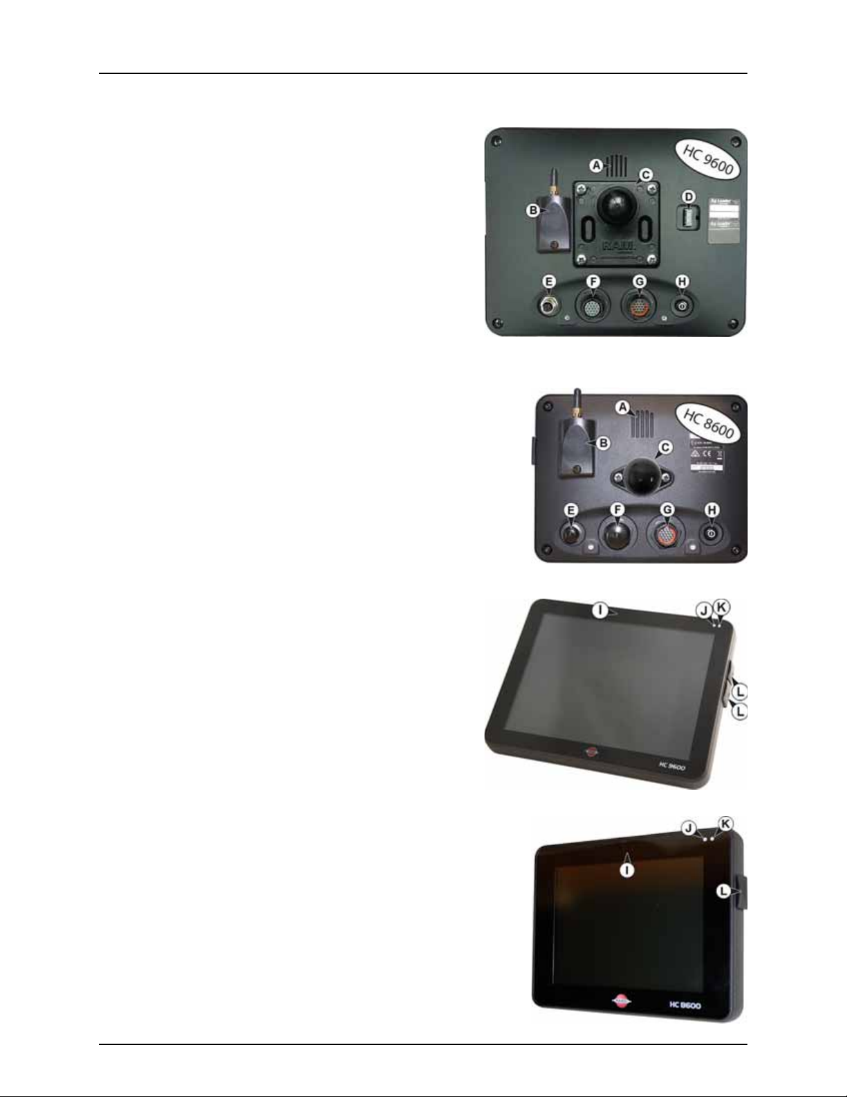
Display Hardware
Rear
A. Speaker
The built-in speaker is used for audible warnings. The volume can
be adjusted through the display setup routine.
B. WiFi
802.11 communication.
C. RAM mount
D. HDMI OUT (HC 9600 only)
E. Ethernet Connection
4-pin connection used for communication with ParaDyme,
GeoSteer, SteerCommand, OnTrac3.
F. 19-pin auxiliary connection
Used for camera input.
G. 19-pin plug
The 19-Pin round display connector contains CAN, RS-232 serial, and system
power and ground connections. It is compatible with some certain other
displays.
H. Power/Reset switch
The Power/Reset switch is used for turning the display on and off in
installations where the system is connected to a continuous power supply.
If the display ever stops responding, the manual power switch may be held
in for five seconds to restart the system. Only do this as a last resort, data loss
could occur during times of improper shutdown.
Front and Side
I. Built in lightbar
For guidance.
J. Light sensitivity sensor
Used to automatically dim the display during nighttime or lowlight situations.
K. Power light
The power light displays one of three states:
Green = ON
Pulses amber = Standby Mode
Solid amber = Running on battery power
L. Side mount USB media slots
• 2 slots for HC 9600
• 1 slot for HC 8600
Used for data transfer in and out of the display.
Used to charge mobile devices up to 1.2 amps.
12
Page 15

3 - Description
USB Flash Drive
The display utilizes a USB Flash Drive slot that you can use to save and transfer your data in and out of the display.
ISOBUS Technology
The ISOBUS system uses Controller Area Network (CAN) technology. CAN systems are comprised of individual modules, each
with their own high speed processor, connected through a high-speed communications cable.
CAN has many benefits:
• Greater ability to configure and expand the system.
• Compatibility.
• Simpler installations with less wiring.
• Increased system dependability.
Color Touch Screen
Here are a few key things to remember if you are new to using a touch screen device:
• Do not use any sharp objects for running the touch screen device, this could result in damage to the display. Using the
tip of a finger is the recommended method of operating the display touch screen.
• Do not use any harsh chemicals to clean the touch screen. Using a damp soft cloth or an anti-static wipe made
specifically for cleaning computer displays is the correct way to clean the screen and the enclosure.
• The display uses a capacitive screen that is heat sensitive. It requires only a brief, gentle touch to operate correctly. A
common mistake is to try to navigate too quickly through the system using firm taps instead of gentle presses.
13
Page 16
3 - Description
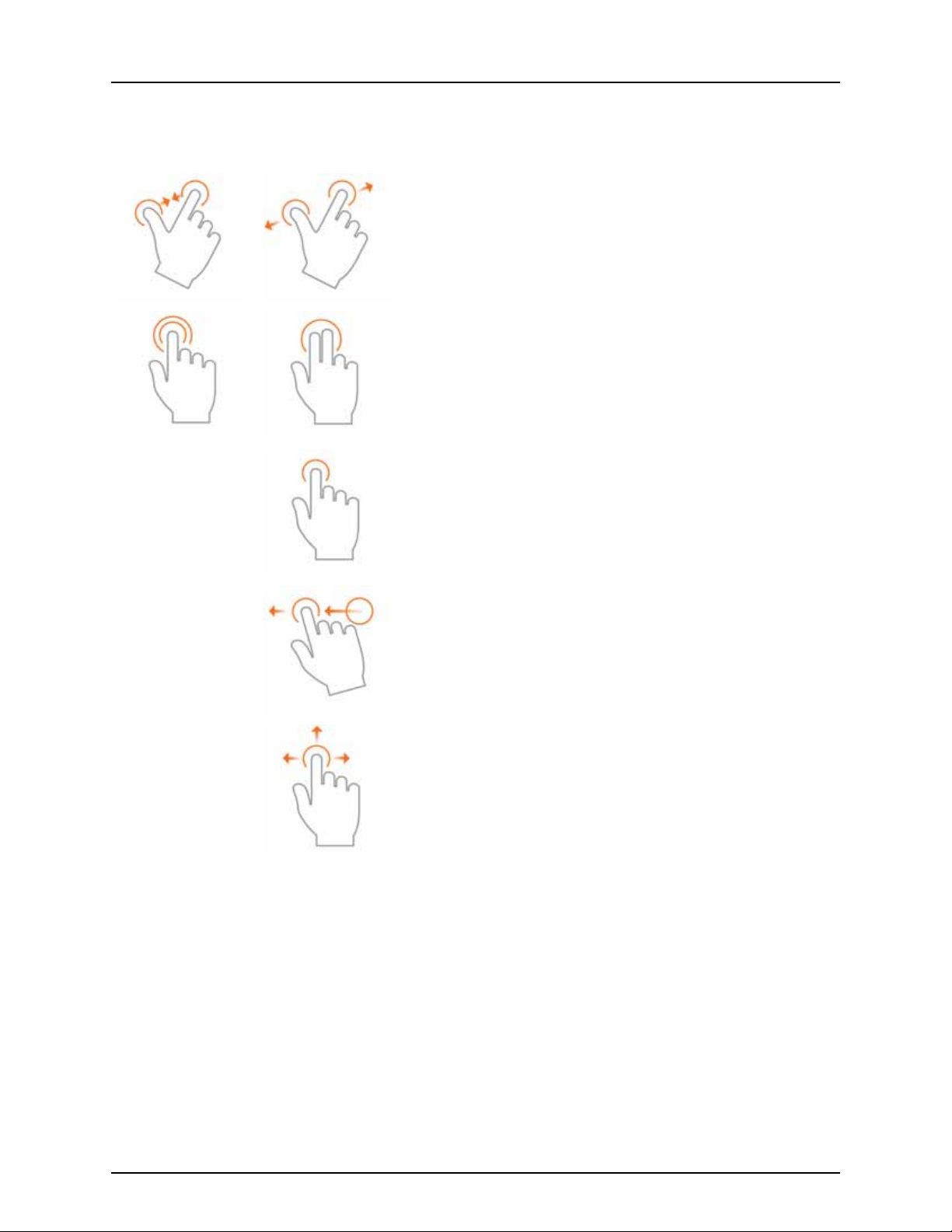
Gestures
As with any smart phone or pad you can use gestures. These gestures will allow you to navigate around the map screens,
select items and make various changes. The most common gestures are outlined below.
Pinch In and Out
Using two fingers touch the screen and pinch in and out to adjust the
zoom level of your map. If zoomed out enough field coins will begin to
appear and allow you to view other maps. If zooming in far enough you
should begin to see row by row data on applicable fields.
Tap to Zoom
By tapping on the map you can quickly control the zoom level of your map.
Quickly double tap with one finger to zoom in and tap with two fingers
together to zoom out.
Tap
Tap items to select them. You can also tap on your map to set a manual
location within the field and view its specific data in the stat cards.
Swipe
Swipe your finger to see additional menus on certain items.
Pan
Tap and hold your finger on the screen to pan around your mapped data
while maintaining the same zoom level.
14
Page 17
3 - Description
Symbols
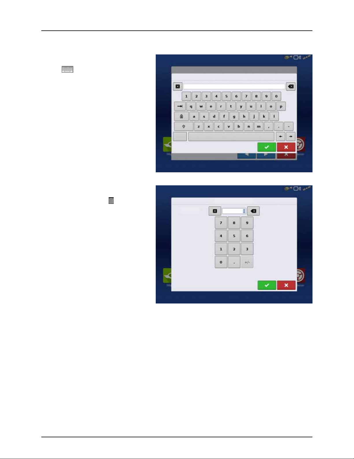
Screen Icon Conventions
The following control buttons are made available for entering names and calibration values into the system.
An on-screen Keyboard is made available when
appropriate for use during all setup processes.
Press the button to access the on-screen text
entry screen.
An on-screen Numeric Keypad is made available
for changing configuration settings and
calibration numbers. Press the button to access
the on-screen numeric entry screen.
15
Page 18

3 - Description
Initial Start-up
General info
An Initial Setup wizard is presented on start-up. The wizard is presented if the display is brand new out-of-the-box.
NOTE! Not all of the following parts may be required to follow - it depends on your specific setup.
÷
Once the wizard is completed, it is not shown again unless the display memory is cleared.
Initial Setup Wizard
The Initial Setup wizard will take you through the following setup items:
Time\Date, Time Zone, Unit System, Language
• Advanced Options. See “Advanced Options” on page 35.
• Restore Backup.
• Upgrade Firmware.
• Unlock Display Features.
Single or Multiple Display Setup
• Single
Use single display if this is the only display that is getting setup.
• Multiple Display
Use multiple display if there is more than one display in the operation and the plan is to share management data
between displays. After initial setup is complete, enter management information and create an .agsetup file.
NOTE! Using the Restore backup option is not the proper method to get multiple displays set up to be the same. Use
÷
the .agsetup file.
It is acceptable to complete the Initial Setup wizard and then upgrade. Setup information will not change.
• On a “clean” display going out for service, to stand in for a failed display, the customer should use the Restore backup
option in the Initial Setup wizard.
ATTENTION! The business created on the first display, and any other management and equipment items, will be
μ
imported to the additional displays.
16
Page 19
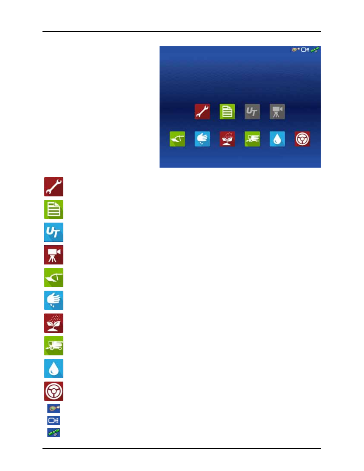
Home Screen Layout
Setup
Summary
Universal
Ter mi na l
Camera
Harvest
Tillage
Planting
Application
Water
Management
Guidance
Setup Access display’s setup items.
3 - Description
Summary Used to access previously logged data, maps, reports.
Universal Terminal Used to interact with UT based ECU’s. It must be enabled in setup.
Camera View cameras attached to the display. It must be enabled in setup.
Tillage Create configuration or start operation specific to tillage.
Planting Create configuration or start operation specific to planting.
Application Create configuration or start operation specific to application.
Harvest Create configuration or start operation specific to harvest.
Water Management Create configuration or start operation specific to water management.
Guidance Used to start guidance steering only operation.
AgFiniti Status Indicator
Devices Status Indicator
Satellites Status Indicator
17
Page 20
3 - Description
GNSS
CAN
Operator
Data Transfer
Remote
Most of the functionality of the display is not available until the basic setup process is completed.
You must complete these initial configuration steps for the Run Time Environment to be active:
• Equipment Operating Configuration.
You can access Configuration Setup by pressing or pressing an app specific to a field operation.
• Product setup.
• Start Field Operation.
Status Indicators
Status Indicators are used to show different states of external equipment connected
to the display (for example: , , and ) and provides easy access to data transfer and
diagnostic features of the display.
18
Page 21
8.99 ac
Field
Boundary
Spray Pump
Wheel Speed
Volta ge
Water
Flow:
Container:
Sensitivity:
Targ et H eigh t:SoilMode:
Tank Vol ume
Headlands
Top og ra ph y
3 - Description
Map Screen
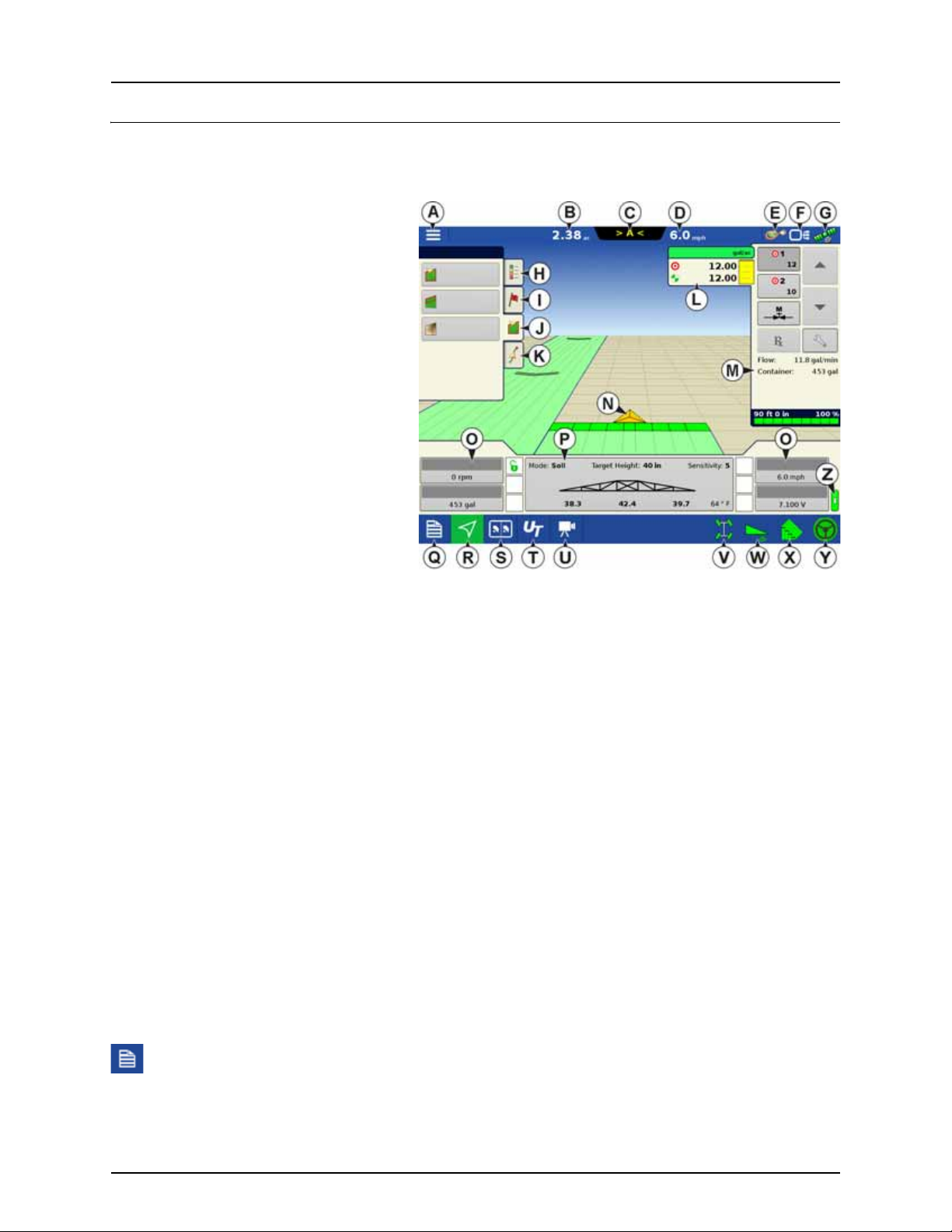
Work Screen
The appearance of the Map screen varies, depending upon which operation you are performing, and your specific operating
configuration.
A. Menu
B. Area Covered
C. Path Indicator
D. Speed
E. AgFiniti Status Indicator
F. Diagnostics Status Indicator
G. GNSS Satellite Status Indicator
H. Legends Tab
I. Markers Tab
J. Field Operations Tab
Guidance Tab
K.
L. Product Tab
M. Product Control Toolbox
N. Vehicle Icon
O. Equipment Tab
P. AutoTerrain/AutoHeight Settings
Q. Summary Screen
R. Map Views
S. Split-Screen (HC 9600 only)
T. Universal Terminal
U. Video Button
V. 4-Wheel Steer Logging Button
W. AutoTerrain/AutoHeight ON/OFF
X. AutoSectionControl (Autoswath)
Y. AutoSteer Button
Z. Main ON/OFF Switch Status
The task bar displays function buttons to the left (Q to U), and status indicators to the right ( V to Y) relating to various
functions of the display. These buttons are shown in front of a green background when function is enabled or you are at that
screen; otherwise they are shown in front of a blue background.
Buttons and indicators are explained in the following:
Equipment Tabs
Different Display Items can be selected by pressing the Equipment tabs (O).
Summary Screen
Pressing the Summary screen button takes you to the Summary Report screen. See “Summary Report” on page 171.
19
Page 22
3 - Description
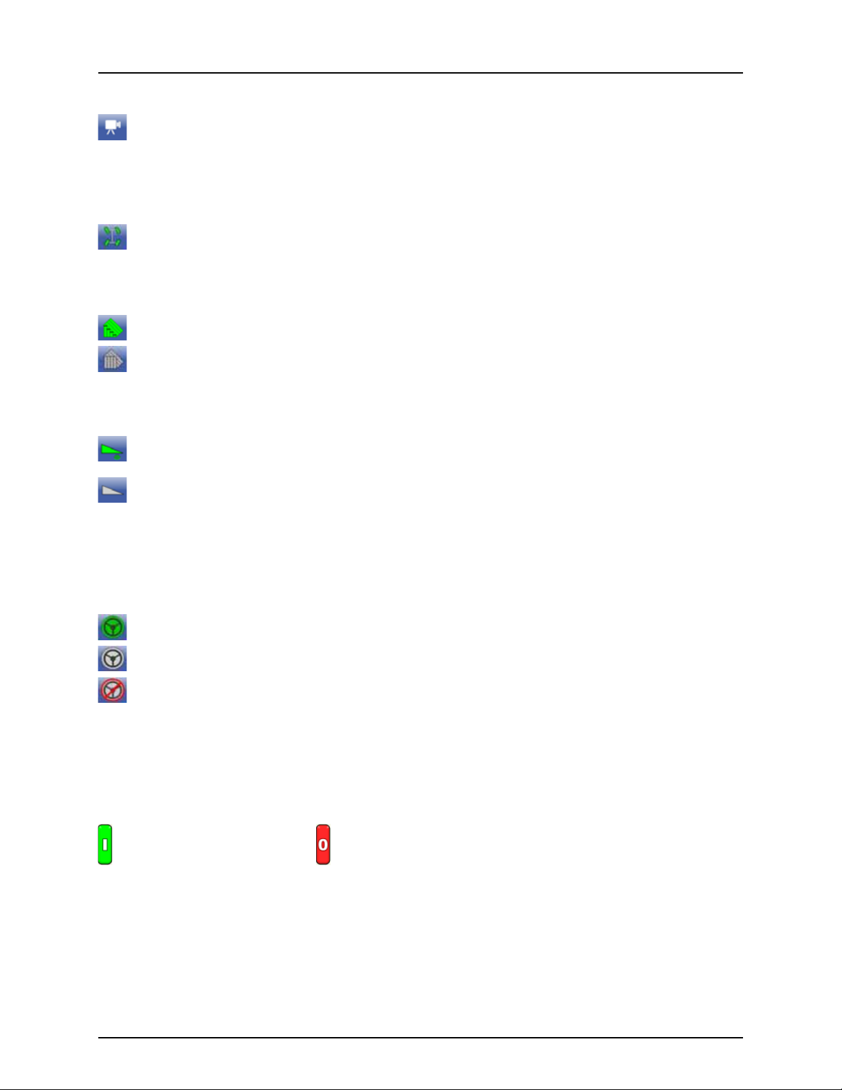
Video Button
Pressing this button takes you to the video screen. Pressing this button repeatedly cycles through the video inputs.
NOTE! For more information on the Video screen, see “Video” on page 27.
÷
4-wheel Steer Button (Self-Propelled only)
Activates logging of 4-wheel steering for AutoSectionControl.
AutoSwath Button
Pressing this button turns the AutoSwath (AutoSectionControl) feature on and off.
AutoSwath - ON
AutoSwath - OFF
AutoTerrain/AutoHeight button
The AutoTerrain/AutoHeight Engage button enables boom height control.
AutoTerrain/AutoHeight Engage - Enabled (Automatic Mode)
• When enabled the display beeps three times.
AutoTerrain/AutoHeight Engage - Disabled (Manual Mode)
• When you disable Automatic Mode on any part of the boom and the display switches to Manual Mode, this
button turns gray and the display beeps twice.
• If less than the full boom remains in Manual Mode, the display will continue beeping twice every three seconds.
AutoSteer Button
The Engage icon status of the AutoSteer system. The appearance of this icon displays the following:
AutoSteer is ON and ready to use.
AutoSteer is OFF but ready to engage.
AutoSteer is OFF and unable to engage.
NOTE! For more information, see “Steering” on page 115.
÷
Master Switch Status
This bar shows that the Master Switch is active.
Master Switch - ON (GREEN) Master Switch - OFF (RED)
20
Page 23

GPS Signal Indicator
The GPS button in the upper right-hand corner of the Map screen, displays the following colors:
Differential GPS
Green if you are receiving a differential GPS signal
GPS - No differential
Ye l l ow if you are receiving GPS, but no differential signal
No GPS
Gray if you are receiving no GPS signal.
Device Information button
Opens screens that display Device Information, Memory, Display, and display diagnostics.
NOTE! For more information, See “CAN Diagnostics” on page 183.
÷
3 - Description
Vehicle Icons
Vehicle Icon - When Zoomed Out
This gold colored triangle indicates the display is in “zoom to extent” mode. When in “zoom to extent” mode the
vehicle implement does not appear, but logged data will still populate on the map.
Vehicle Icon - logging
If the vehicle is logging, the implement icon appears with a green bar below it.
Vehicle Icon - logging (with all sections ON)
If the vehicle is logging data from an implement split into sections, (for instance during a planting or application
operation), then these sections appear in the implement icon.
Vehicle Icon - not logging
If the vehicle is not logging data, then the implement icon appears with a gray bar.
Vehicle Icon - Master Switch Off
When the master switch is off, the vehicle will show a thinner red bar.
21
Page 24

3 - Description
Corn
Yield
Legend
Save as Product Legend
Reset to Default
Legend
Automatic
Legend
Legend Settings
Attribute: Rate
Average
Color Scheme
Range Spacing
Range
Green-Yellow-Red
Legend
Map Toolbox
Legend Settings
The Legend Settings screen allows you to change the default legend. On the map legend tab, press
anywhere on the legend and the legend settings screen appears.
NOTE!
÷
• The Legend Settings screen can also
be accessed by pressing the Edit
Legend button on the Setup screen’s
Product tab.
• Legend settings changes that are
made at the Legend Settings screen
will affect all regions.
The Legend Settings screen includes the following
items:
• Attribute
Appears at the top left of the Legend Settings screen. Attributes shown for Harvest include Yield and Moisture. The
Rate attribute is shown for Planting and Application operations. You can adjust the color scheme, spacing and ranges
as they appear on the map screen, by using the buttons described below.
• Average
The Average button changes the average rate for the legend. Press to specify the average of the ranges
shown on the map legend.
• Range Spacing
The Range Spacing button changes the difference between the rates in one color range. Press to edit the
legend range spacing value, which is the total number of units represented by a particular color.
• Ranges
The Ranges / change the number of range increments displayed in the legend.
• Color Scheme
The Color Scheme can be modified by using the drop-down list. Choices include the following:
• Green-Yellow-Red
• Single Hue (blues or greens)
• Rainbow
• Reset to Default Legend
Resets the legend to the default settings.
22
Page 25
3 - Description
Water
RATE
Load
Reference
Map Options
Data
Perspe ctive
Row Outlines
Grid
Trave l Direc tion
Clear Map
Map Shift
Follo w View
Legend
• Automatic Legend
If the “Automatic Legend” check box is selected, the average automatically sets itself to the field average and updates
as the field average changes.
• Save as Product Legend
Select the “Save as Product Legend” check box if you wish to set the current legend as the default legend for all regions
of the same product.
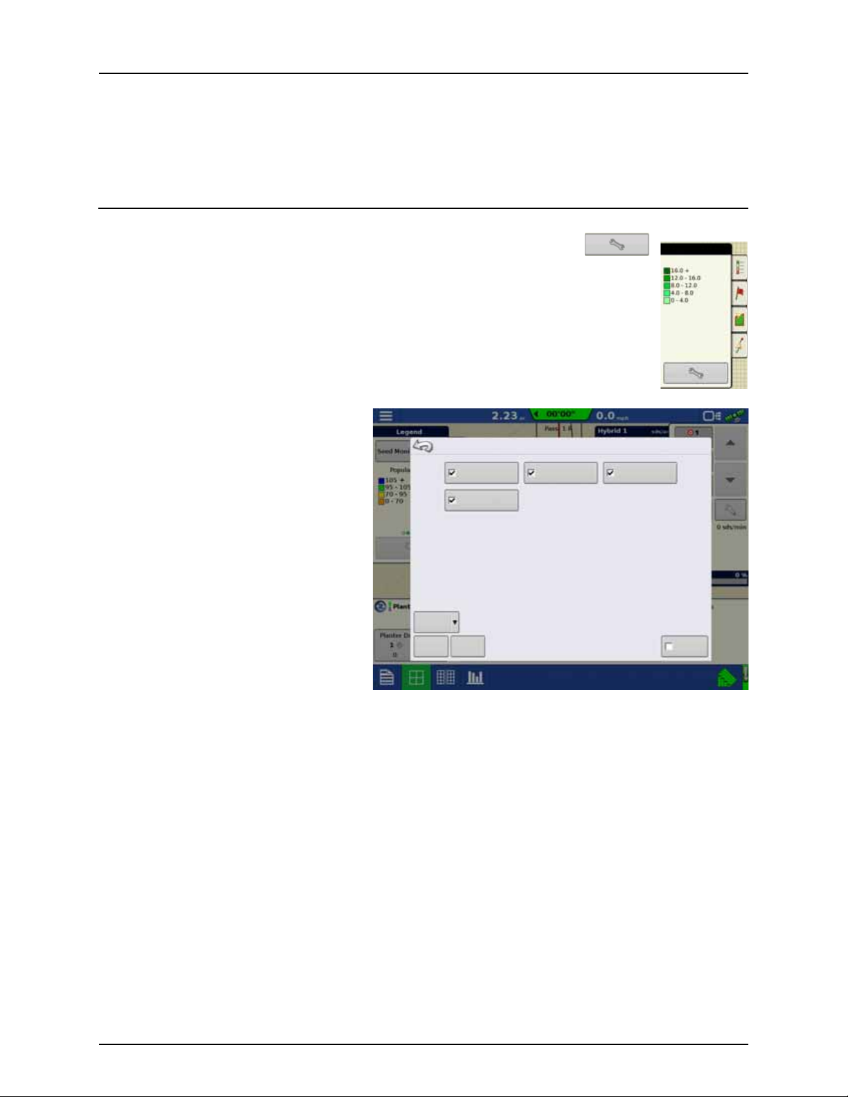
Map Options
Here you can toggle mappable items, load references, or clear map. Press the Legend Setup
and the Map Options screen appears.
Clear Map
•
Permanently removes on-screen map from
the active field operation, but the log data
will still be exported to the USB drive.
WARNING! Once you clear the map, this
±
information cannot be retrieved.
• Load Reference
Loads a list of maps of previous operations
performed in that field. For each operation,
you can view As-Applied or Coverage
attributes; and Varieties if you are performing
a Planting operation.
23
Page 26
3 - Description
Map Shift
Map Shift
Reference Point Set
Going Back to Reference Point
Map Shift
Map Shift is used to shift the onscreen map and account for time base inaccuracies with lower accuracy GPS
receivers. This is done by doing a quick survey and creating a reference point. Any time the user would like to
adjust the map to fix GPS drift inaccuracies, they can go back to the reference point and perform a survey to
shift to the current position.
Map Shift General Guideline
For Map Shift to be successful, it is suggested that a reference point be set before beginning a field operation. That way any
time the vehicle leaves the field or is shut down for an extended period of time, the reference point can be used upon
returning to the field operation.
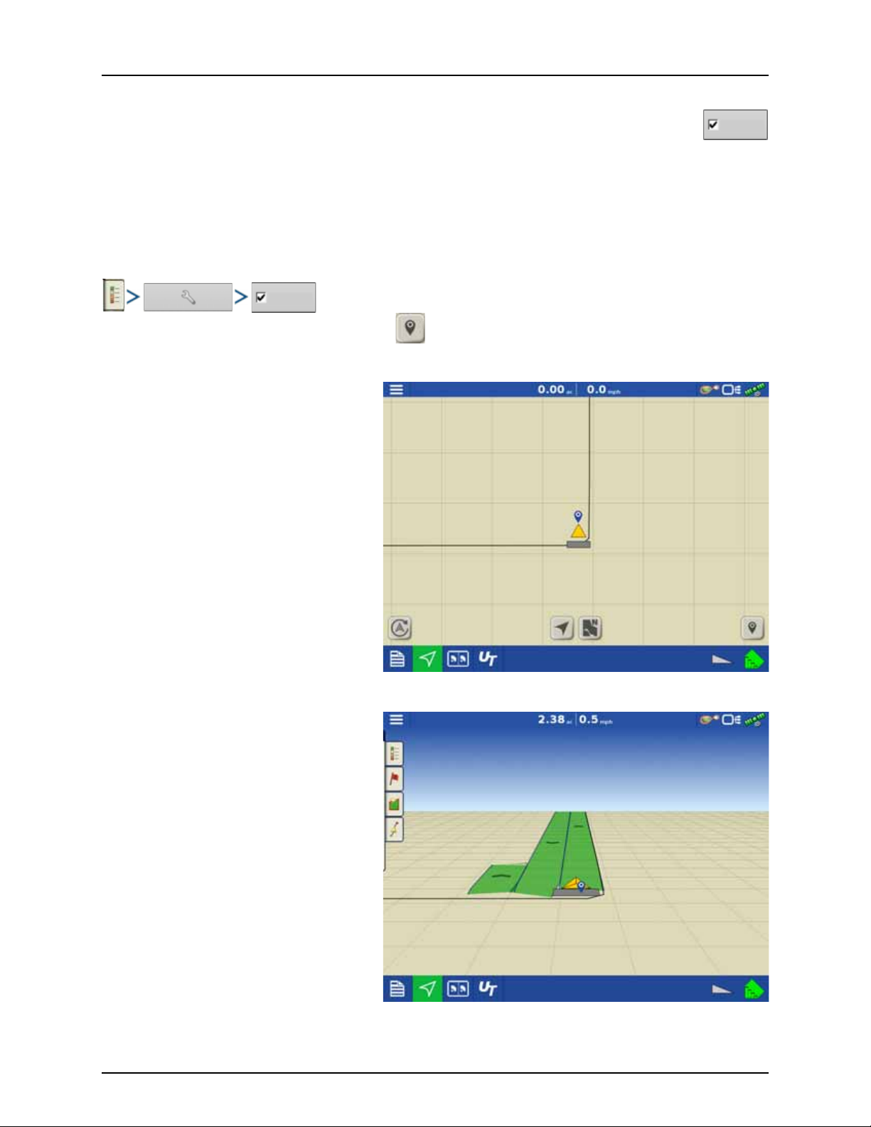
Enable Map Shift
With the map shift option checked, the map shift icon will become available when in full screen view on the mapping
screen.
Shifting the Map
1. Press the map shift icon to access Map Shift
Options.
2. Determine a good location to create a
reference point. For Map shift to work
properly, it is vital that the GPS receiver be
able to get back to the exact same point each
time a shift is required.
3. Once a spot is located, press “Set” on the Map
Shift options page to begin the 10 second
survey.
4. Once the survey is complete, the reference
point will be set. On the Mapping Screen, the
reference point is shown by a blue pin drop.
24
Page 27
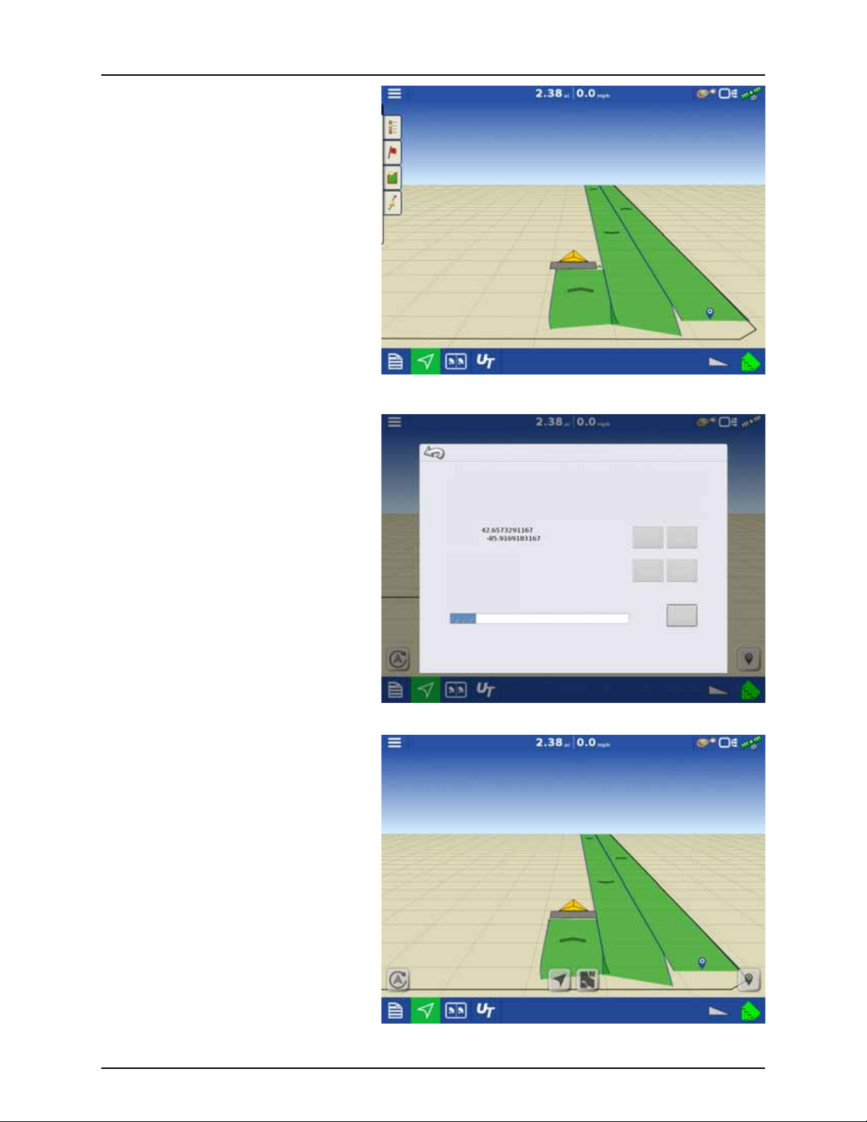
5. When a map shift is required, go back to the
Shifting Map
Map Shift Options
Set saves a reference point
Shift moves the map to match the current position
Ensure GPS receiver is always at the same location is was when the reference point
was created
Reference point
Latitude:
Longitud e:
Current Position
In Progress
Positi on Surve y
Time Remaining: 9 s
Clear Set
Clear Shift
Cancel
set reference point and make sure the GPS
antenna is back in the original location.
6. Access the Map Shift Options menu and
press the “Shift” button.
3 - Description
7. “Shift” will start a 10 second survey and
update the map with the new current
position.
8. Any time a reference point or shift needs
cleared, it can be accomplished via Map Shift
Options.
25
Page 28
3 - Description
Legend Legend
Water Wat er
Rate
Perspective
Follow View
Top -D ow n
Follow View
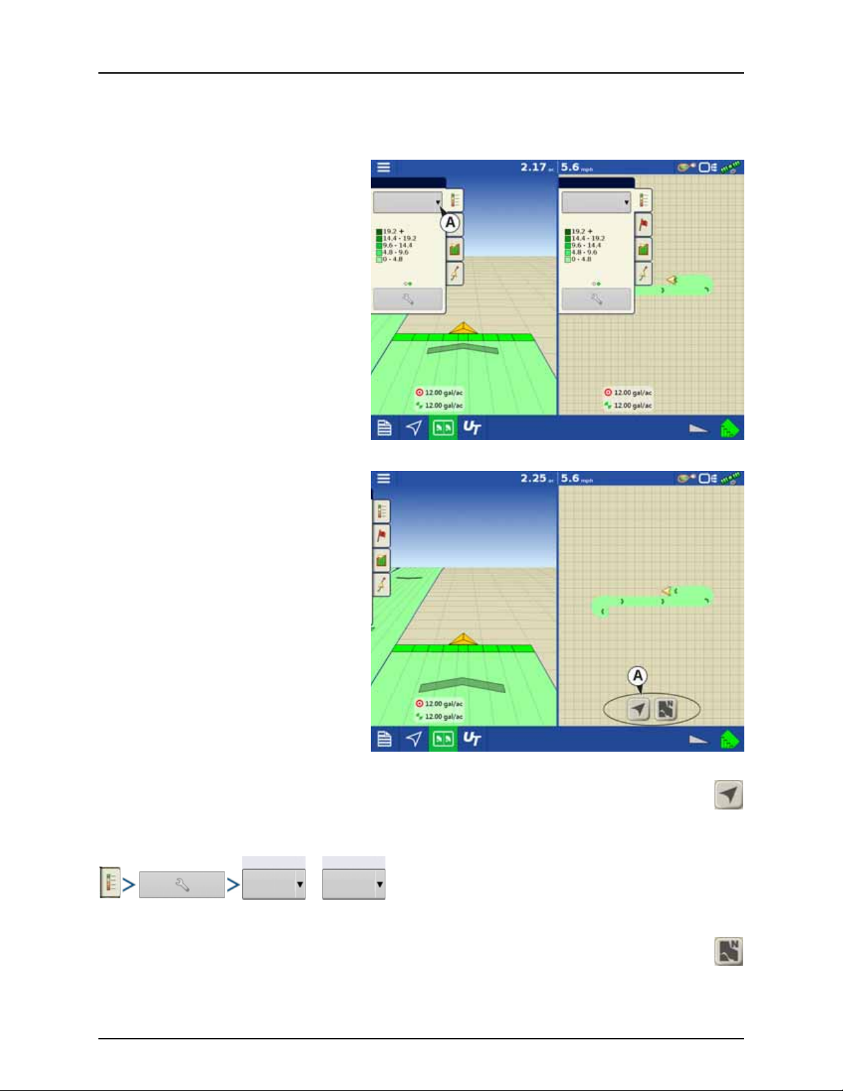
Split-Screen Map
The HC 9600 has the capability of showing multiple views at the same time from the map screen. This has multiple uses like
showing guidance in perspective view and zoom extents view at the same time, splitting the screen between guidance and
Universal Terminal, or watching two products at the same time like planting and liquid application.
Maps can be selected individually from the legend
drop-down.
Map views can be changed by tapping anywhere
in the center of the left/right side map then
choosing from one of the views buttons (A).
Follow View
Sets the map to follow the vehicle icon. The default Follow View can be set to either Perspective view or Top-Down
view.
Setting the Follow View mode:
or
North Oriented View
Zooms the map out to the full extent of the field boundary or mapped area and orients the map north, regardless of
the vehicle’s direction of travel.
26
Page 29
3 - Description
Volume rate
gal/acre
PF bus + PF bus -
Volt Volt
Agitation
%
Voltmeter
Volt
Volume rate
gal/acre
Markers
Rock
Washo ut
Weeds
Trees
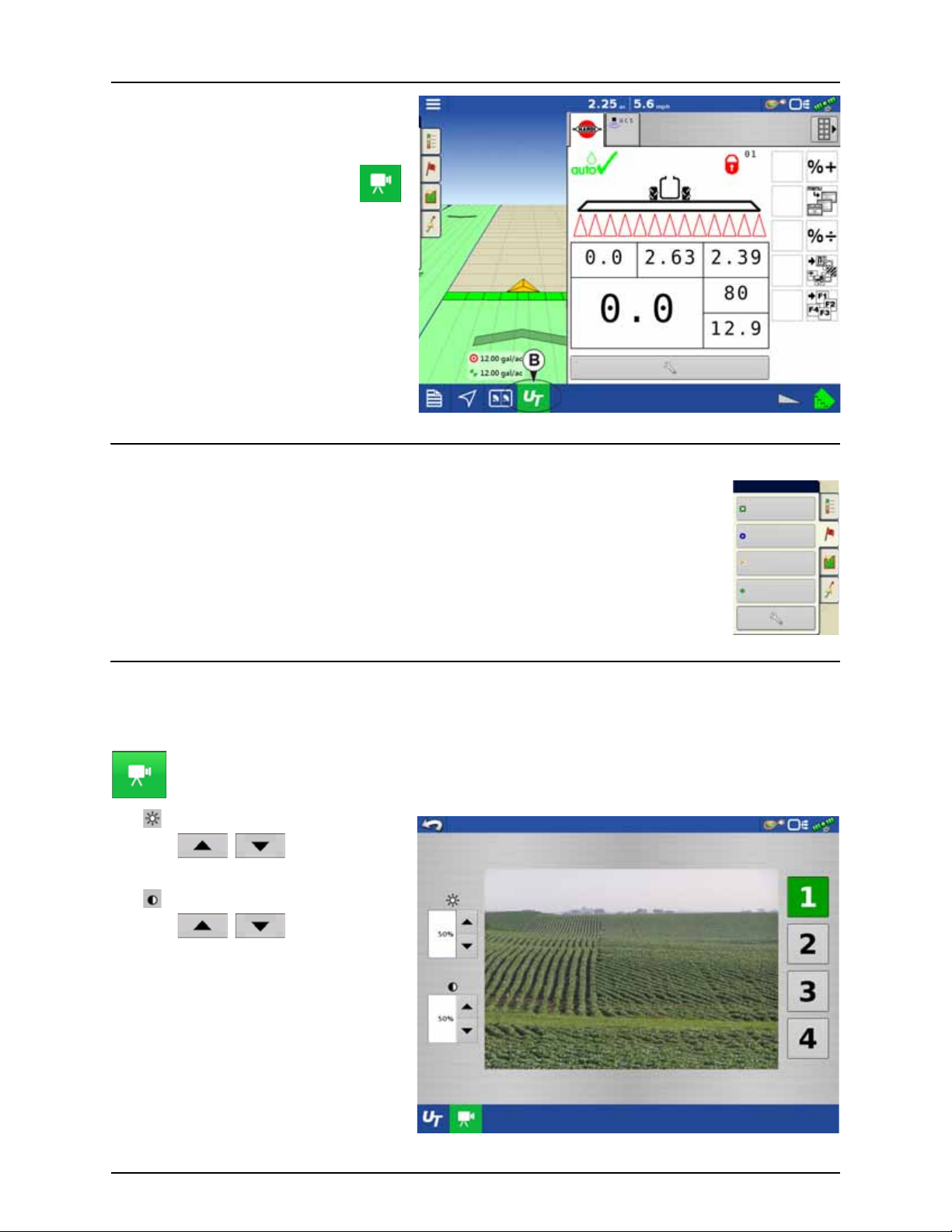
By pressing the UT button (B) from the map screen,
the display will split the screen between Map
screen and Universal Terminal.
In same manner with Cameras attached,
pressing the video button will split the
screen between the active map and the
video page.
Markers tab
Markers are a collection of point objects that are available on the Map Markers tab of the Mapping
toolbox. Map markers allow you to map points on the go in order to identify specific features within a
field. Press an individual marker to indicate a Map Marker on the Map screen.
If all of the Markers that you created are not immediately visible in this screen, swipe the tab to view
more markers that you created.
Video
NOTE! Video is only available when enabled in the Console Setup menu - see “Display Button” on page 84.
÷
Video button. Camera is available from the Home or Map screen. Press video button and the Video screen appears.
• Brightness
Press / to increase or
decrease the brightness of the video input.
• Contrast
Press / to increase or
decrease the contrast of the video input.
• Camera Number Selection
The display can receive input from up to four
video cameras. Press the numbered buttons
to switch views between video cameras.
NOTE! You can adjust the brightness and
÷
contrast of each input individually.
27
Page 30

3 - Description
AgFiniti
General Info
AgFiniti is a platform to provide users with the ability to quickly and easily transfer data, view their display remotely, and take
logged data with you when you leave the cab.
AgFiniti Mobile
AgFiniti Mobile is Ag Leader’s native iOS app. It provides the ability to take maps and summary information from the cab
instantly and access it on an iPad anywhere. The app allows for a direct connection to the display, reducing the need for a
modem or Wi-Fi hotspot in the cab and provides a simple, direct connection to access data. AgFiniti Mobile also allows for
multiple display connections, allowing for operations with multiple displays to have their logged data all in one iPad. Lastly,
it is a permanent storage solution; data imported into Mobile will remain there until removed by the user or the app is
uninstalled. See “AgFiniti Mobile” on page 135.
File Transfer
AgFiniti File Transfer is a wireless file transfer solution. It allows the user the ability to both access and export data to and from
the cloud. This results in data being accessible anywhere without requiring a USB drive. You can export prescriptions and
management information from SMS and have them instantly accessible in your tractor by using AgFiniti File Transfer. File
Transfer also allows for the sharing of data with other users and trusted advisors, again, without having to hand them a
physical drive. File Transfer requires an annual license. See “File Transfer” on page 140.
Remote Support
AgFiniti Remote Support grants the ability to remotely view a display from the AgFiniti website on supported browsers. This
allows for faster, more effective troubleshooting due to the user being able to view the display and not relying on secondhand descriptions. This can result in less downtime and fewer frustrations when issues do occur. This can also help when
setting up displays for the first time and provides an avenue for getting help in a more efficient manner. Remote Support
requires an annual license. See “Remote Support” on page 141.
AgFiniti Mobile Connection Types
Display Access Point Mode
This connection type turns your HC 8600/9600 display into a wireless access point that all compatible iPads can connect to.
When using this connection type, every time an iPad is within range of your HC 8600/9600 display, AgFiniti Mobile will
automatically download new data while the app is running.
See “Display Access Point connection type” on page 132 for step by step instructions to make this connection type.
Wi-Fi Network
Connection scenarios:
• Transferring information when both devices are connected to the same home/office Wi-Fi network
• A hotspot (i.e. Jetpack) device is used in the cab to provide internet
When both the HC 8600/9600 display and your iPad are connected to the same network, for example your home Wi-Fi
network, they will be able to recognize one another and transfer data in the same fashion as the other two connection types.
If you already have a Wi-Fi network present in the cab of your vehicle, this connection can be utilized. To use this connection
type, the HC 8600/9600 display and AgFiniti Mobile need to be on the same wireless network.
See “Cellular iPad as Personal Hotspot Connection” on page 142 for step by step instructions to make this connection type.
Cellular iPad as Personal Hotspot
Connection scenarios
• Only Cellular iPads when HC 8600/9600 is accessing AgFiniti Cloud
Cellular based iPads have the ability to act as a personal hotspot. This allows HC 8600/9600 to both access the AgFiniti cloud
and directly transfer information from the HC 8600/9600 display to AgFiniti Mobile, both through the iPad’s cellular
connection and Wi-Fi hotspot. This connection type would need to be used to access AgFiniti cloud. For example you may
need to download an .agsetup file (for prescriptions) from AgFiniti cloud or to use remote support.
See “Cellular iPad as Personal Hotspot Connection” on page 142 for step by step instructions to make this connection type
NOTE! Using this connection type to transfer data directly from the HC 8600/9600 display to your iPad will not utilize
÷
your cellular data. The connection is over Wi-Fi and therefore does not use cellular data. If you use your iPad to
connect to AgFiniti Cloud to download data, then cellular data will be used.
28
Page 31

3 - Description
Miscellaneous
About AutoTerrain/AutoHeight
For the use of AutoTerrain/AutoHeight together with HC 8600/9600, please refer to the specific AutoTerrain/AutoHeight UC5
instruction books.
Glossary of Application Settings
Configuration Settings
• Rate Outside of Field
Rate that will be used outside of the field boundary.
• Zero stops product application.
• Last Good uses the previous rate before exiting the boundary.
• Rx Default uses the default rate written in the prescription file loaded.
• Rate Change Look-Ahead
Compensates for any delay in the control system when changing between different product flow rates during variable
rate application. This setting can be thought of as a “look ahead” value when using a variable rate prescription.
The display will send the signal to change rates before hitting a transition line so that the applied rate is correct when
crossing into the new management zone.
• The typical setting range for this is 0-1 seconds.
Speed Input Settings
• Primary Speed Source
Main source used by the display.
• Backup Speed Source
If the primary speed source fails, the display will use the backup if one is available.
• Manual Speed
If both of the sources are unavailable, manual speed can be used in order for the control channel to provide application.
Manual speed setting is for use during static machine testing or by the control system in the absence of primary and
backup speed signals.
Automatic Swath Control Settings
• Turn-On Look-Ahead
Determines how far ahead the system looks to turn the swath sections back on. This setting compensates for any delay
in the product control system when the sections are turned on.
• Turn-Off Look-Ahead
Determines how far ahead the system looks to turn the swath sections off. This setting compensates for delay in the
product control system when the boom sections are turned off.
• Outside Boundary Option
Determines the behavior of the sections when exiting the field boundary or prescription-mapped area.
• Coverage Option
Based on the coverage option selected, this setting determines the behavior of the swath section when
entering/exiting an already applied area or field boundary.
Options available include:
• Minimize Skip
• Minimize Overlap
• User Defined Percentage.
Run Screen
• AutoSwath (AutoSectionControl)
Use to enable/disable automatic control of boom section on/off state based upon field boundaries, prescription files,
and previously applied areas.
29
Page 32

3 - Description
30
Page 33

4 - System setup
Installation
Installation Instructions
Mount the display to a secure support inside the vehicle cab. When choosing a mounting location consider if the display:
• is readily accessible to the machine operator.
• does not obstruct the machine operator's normal driving view.
• does not interfere with or limit access to any of the existing machine controls.
• is fitted so the ISOBUS system cabling is routed and secured without interfering with existing machine controls.
WARNING! If drilling holes is required during the mounting process, care must be taken to ensure that damage is not
±
done to existing vehicle wiring, mechanical, or cab structure. Refer to vehicle manufacturer documentation for
specific details on your equipment. Follow all OEM instructions, cautions, and warnings when working around
equipment.
Components of Ram mount kit:
• 9600 Display: HARDI® Part #72802400
• 8600 Display: HARDI® Part #73156900
A. RAM Base
B. RAM Arm
C. Base
31
Page 34

J02
J04
P01
J03
J01
J05
J06
J04
J06
J10
J09
J01
J03
A
G
C
J07
J08
P02
M
J01
P01
J02
P01
D
J03
P02
P03
J06
J07
F01
J02 J01
J05 J06
J01
J02
H1
H
F
B
4 - System setup
Cable connections
Non ISOBUS Tractor
A. 26069200/4004664-1
Display cable, Guidance activation - 3.8m
J01 - Display Main
J06 - Guidance Activation
P01 - Power IN
J05 - CAN A
J04 - GPS
J03 - ISOBUS
J02 - Digital I/O
J07 - Display Ethernet
J08 - Ethernet Out
C. 26040900/ 4002820-1
Power, display/guidance
J04 - Power 5A
J06 - Power 15A
J09 - Battery ground
J10 - Battery power
J01 - Fuse, 5A blade style
J03 - Fuse, 15A blade style
B. 26069400/ 4004666-1
ISOBUS Retrofit cable
P01 - Display cable
P03 - ISOBUS out
J07 - ECU Power
J03 - IBBC Relay Module
P02 - IBBC Relay Module
F01 - Fuse, 5A Blade style
J06 - Battery power
D. 26040500/ 4002825
ISOBUS Termination Assembly
J02 - ISOBUS
J01 - Active terminator
F. 26040600/ 4002827-16
ISOBUS Power Cable
H. 26040300/ 4002826
ISOBUS IBBC
M. 26069900/ 4004668-1
ISOBUS Joystick Tee cable
J01 - ISO CAN Out
P01 - ISO CAN IN
P02 - Grip Connector
J02 - Jumper
G. 26031500
HARDI® Grip and SetBox cable
Grip and SetBox kit include the cable G.
Display cable kit 83365003 includes cables:
A, C, D and M.
Tractor ISOBUS kit 83365103 includes cables:
B, D, F and H.
32
Page 35

J02
J04
P01
J03
J01
J05
J06
J04
J06
J10
J09
J01
J03
A
G
C
J07
J08
P02
N
P01
J03
J07
J02
K
ISOBUS Tractor with cabin connector
Display, SetBox and Grip connected to cabin connector.
4 - System setup
A. 26069200/4004664-1
Display cable, Guidance activation - 3.8m
J01 - Display Main
J06 - Guidance Activation
P01 - Power IN
J05 - CAN A
J04 - GPS
J03 - ISOBUS
J02 - Digital I/O
J07 - Display Ethernet
J08 - Ethernet Out
C. 26040900/ 4002820-1
Power, display/guidance
J04 - Power 5A
J06 - Power 15A
J09 - Battery ground
J10 - Battery power
J01 - Fuse, 5A blade style
J03 - Fuse, 15A blade style
N. 26069500/ 4004667-1
ISOBUS Adapter
P01 - Display cable
J07 - ECU power
J03 - Jumper
P02 - Cab Post Extension
J02 - Cab Post Connection
G. 26031500
HARDI® Grip and SetBox cable
K. Cabin connector - tractor ISOBUS
Grip and SetBox kit include the cable G.
Display cable kit 83365003 includes cables:
A, C and N.
33
Page 36

J02
J04
P01
J03
J01
J04
J06
J10
J09
J01
J03
A
G
C
J07
J08
J04
L
E
J02 P02
P02
M
P01
J01
J02
P01
J06
J05
4 - System setup
ISOBUS Tractor without cabin connector
A. 26069200/4004664-1
Display cable, Guidance activation - 3.8m
J01 - Display Main
J06 - Guidance Activation
P01 - Power IN
J05 - CAN A
J04 - GPS
J03 - ISOBUS
J02 - Digital I/O
J07 - Display Ethernet
J08 - Ethernet Out
Connector J07 and J08 are only present on
the 3,8m cable.
C. 26040900/ 4002820-1
Power, display/guidance
J04 - Power 5A
J06 - Power 15A
J09 - Battery ground
J10 - Battery power
J01 - Fuse, 5A blade style
J03 - Fuse, 15A blade style
M. 26069900/ 4004668-1
ISOBUS Joystick Tee cable
J01 - ISO CAN Out
P01 - ISO CAN In
P02 - Grip Connector
J02 - Jumper
E. 26034403/4004301-1
P01 - Display cable
J04 - ECU Power
J02 - ISO CAN B Out
P02 - ISO CAN B In
G. 26031500
HARDI® Grip and SetBox cable
L. Tractor ISOBUS
Grip and SetBox kit include the cable G.
Display cable kit 83365003 includes cables:
A, C, E and M.
34
Page 37

Initial Start-up
Display Setup: Select Language
Language
English/US
Advanced
Featu re
Unlocks
Upgrade
Restore
Restore data from a backup file (same display model only)
Upgrade the display firmware.
Unlock display featu res.
Advanced Options
General info
An Initial Setup wizard is presented on start-up.
NOTE! Not all of the following parts may be required to follow - it depends on your specific setup.
÷
Once the wizard is completed, it is not shown again unless the display memory is cleared.
Advanced Options
Press “Advanced” button on Language Selection
screen (first screen to appear on initial start-up).
4 - System setup
Select:
• Restore Backup
• Upgrade Firmware
• Unlock Display Features
NOTE! Using the Restore backup option is
÷
not the proper method to get multiple
displays set up to be the same. Use the
AGSETUP file.
It is acceptable to complete the initial setup wizard
and then upgrade. Setup information will not
change.
• On a “clean” display going out for service, to
stand in for a failed display, the customer
should use the Restore backup option in the
initial setup wizard.
35
Page 38

4 - System setup
Display Setup: Select Language
Language
English/US
Advanced
Display Setup: Select Units System
Unit system
Imperial
Display Setup: Set Date & Time
Time Zone
Americas (Central Time)
Location Specific Setup
1. Language
A. Select your language.
B. Press to confirm.
2. Unit System
A. Press to select units.
ATTENTION! Metric units can also be
μ
selected, but this book covers Imperial
units.
B. Press to confirm.
3. Set Time and Date:
A. Press to select Time Zone.
B. Press to set Time and Date.
C. Press to confirm.
36
Page 39
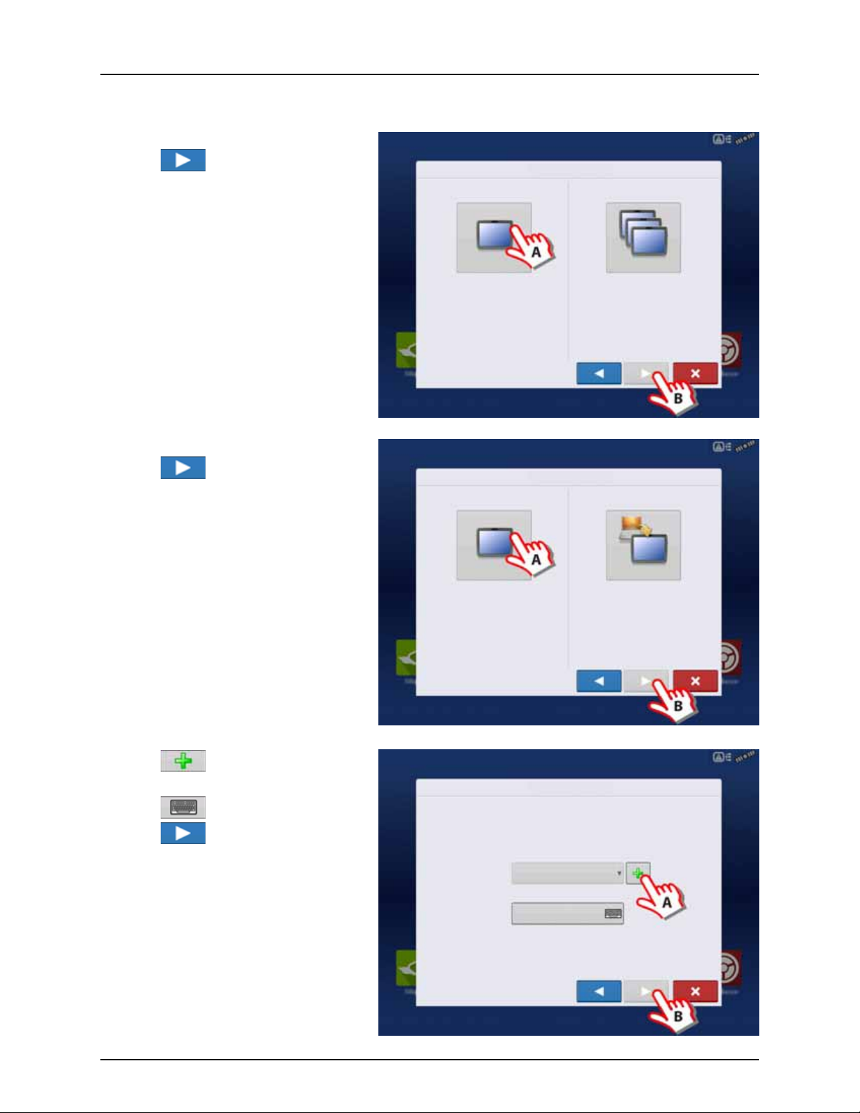
Single Display
Select “Single Display” if you only have one
Integra, Versa, Compass, or HC 9600/HC8500 in
your operation.
Select “Multiple Displays” to share setup
items between Integra, Versa, Compass, and
HC 9600/HC8500 displays.
Single Display
Multiple Display
Display Setup: Select Single or Multiple
Select “New Setup” to perform all setup
through the display user-interface.
Select “Import Setup” to select an AgSetup
file to import setup items from your
computer.
New Setup
Import Setup
Display Setup: Select New or Import
Display Setup: Set Owner
Display Owner (Business Name)
Display Nickname
Used if you have only one display to setup.
A. Press “Single Display” button.
B. Press to continue.
New setup
A. Press “New Setup” button.
B. Press to continue.
4 - System setup
A. Press to enter a Display Owner
(Business Name).
B. Press to enter a display nickname.
C. Press to continue.
37
Page 40

4 - System setup
Select “New Setup” to perform all setup
through the display user-interface.
Select “Import Setup” to select an AgSetup
file to import setup items from your
computer.
New Setup
Import Setup
Display Setup: Select New or Import
Display Setup: Select Ag Setup File
Name Size Date Modified
Import setup
A. Press “Import Setup” button.
B. Press to continue.
A. Select desired setup file from directory.
B. Press to accept the setup and return
to Home screen.
38
Page 41

Press to accept and import setup file.
Display Setup: Review Import
Management
Grower/Farm/Field
Allegon County
New Modified Conflicting Resolved
Seasons
2016 Crop
Products Configuration
Display Setup: Set Owner
Display Owner (Business Name)
Display Nickname
Select “New Setup” to perform all setup
through the display user-interface.
Select “Import Setup” to select an AgSetup
file to import setup items from your
computer.
New Setup
Import Setup
Display Setup: Select New or Import
A. Press to select a Display Owner
(Business Name).
B. Press to enter a display nickname.
4 - System setup
C. Press to accept the setup and
return to Home screen.
Multiple Displays
Setup First Display
A. Press “Multiple Display ” button.
B. Press to continue.
39
Page 42

4 - System setup
Select “First Display” to expor t an AgSetup file
from this display to import into additional
displays (with version 3.0 or higher).
Select “Additional Display” to import setup
items from an AgSetup file from an existing
display.
First Display Additional Display
Display Setup: Select First or Other
Select “New Setup” to perform all setup
through the display user-interface.
Select “Import Setup” to select an AgSetup
file to import setup items from your
computer.
New Setup
Import Setup
Display Setup: Select New or Import
Display Setup: Set Owner
Display Owner (Business Name)
Display Nickname
A. Press “First Display” button.
B. Press to continue.
New setup
A. Press “New Setup” button.
B. Press to continue.
A. Press to enter a Display Owner
(Business Name).
B. Press to enter a display nickname.
C. Press to accept the setup and return
to Home screen.
40
Page 43
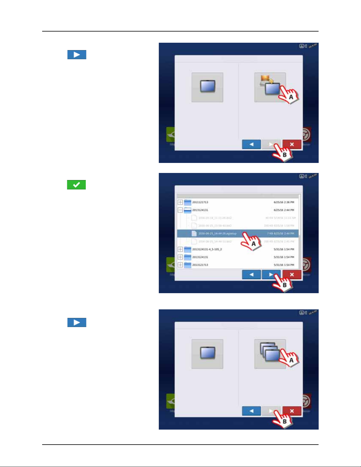
Import setup
Select “New Setup” to perform all setup
through the display user-interface.
Select “Import Setup” to select an AgSetup
file to import setup items from your
computer.
New Setup
Import Setup
Display Setup: Select New or Import
Display Setup: Select Ag Setup File
Name Size Date Modified
Select “Single Display” if you only have one
Integra, Versa, Compass, or HC 9600/HC8500 in
your operation.
Select “Multiple Displays” to share setup
items between Integra, Versa, Compass, and
HC 9600/HC8500 displays.
Single Display
Multiple Display
Display Setup: Select Single or Multiple
A. Press “Import Setup” button.
B. Press to continue.
A. Select desired setup file from directory.
B. Press to accept the setup and return
to Home screen.
4 - System setup
Setup Additional Display
A. Press “Multiple Display ” button.
B. Press to continue.
41
Page 44

4 - System setup
Select “First Display” to expor t an AgSetup file
from this display to import into additional
displays (with version 3.0 or higher).
Select “Additional Display” to import setup
items from an AgSetup file from an existing
display.
First Display Additional Display
Display Setup: Select First or Other
Display Setup: Select Ag Setup File
Name Size Date Modified
A. Press “Additional Display” button.
B. Press to continue.
A. Select desired setup file from directory.
B. Press to continue.
The business created on the first display,
μ
and any other management and
equipment items, will be imported to the
additional displays.
42
Page 45

Import Setup Data
Data Transfer
Import
Files
Display Setup: Select Ag Setup File
Name Size Date Modified
Import
Filename: 2012-03-13_12-37-56.agsetup
Conflicts: 4
Management Products Configuration
Resolve
Corn
Resolve
Use the scroll bar to find the file you wish to
import.
When a setup file is created, it is saved in a folder
titled with the displays serial number _nickname.
The file will include a date and have the .agsetup
suffix.
A. Select desired setup file from directory.
B. Press to continue.
4 - System setup
Highlight item with conflict
.
Press .
43
Page 46

4 - System setup
Rename
Imported
Rename
Existing
Merge
Conflict Resolution
Item to Import Existing Item
Name:
Modification Time:
Creation Time:
Corn Name:
Modification Time:
Creation Time:
Corn
Rename the item being imported.
Rename the existing Item.
Merge the imported and existing items together.
GNSS
CAN
Gene Eilers
Data Transfer
Remote Support
Setup Summary Universal
Ter mi na l
Camera
Tillage Planting Application Harvest Water
Management
Guidance
Conflicts can be resolved by:
• Rename Import
• Rename Existing
• Merge
Product Mixes and Configurations cannot be
merged. The Merge button will be grayed out and
not selectable for these items.
Once all conflicts have been resolved.
Press .
Home Screen
Most of the functionality of the display is not
available until the basic setup process is
completed.
A. Status bar.
B. Status Indicators pull-down menu.
C. Setup button.
You must complete these initial configuration
steps for the Run Time Environment to be active:
ATTENTION! It is strongly recommended to
μ
set up the controller by using the “Universal
Ter m inal” on page 4 5 .
• Grower, Farm, and Field management.
For more information, See “Management
button” on page 74.
• Equipment Operating Configuration.
You can access Configuration Setup by pressing the Setup (wrench) button (C) on the Home screen. For more
information, see “Equipment Setup” on page 72.
• Product setup.
For more information, see “Product tab” on page 72, as well as the additional configuration information described in
each Operations chapter.
• Start Field Operation.
For more information, “Configuration Setup Screen” on page 151.
44
Page 47

4 - System setup
ISOBUS Settings
and
Enable Universal Terminal
Enable Task Controller
Enable Universal Terminal
Broadcast Display Speed (ISO GBSD)
Broadcast GPS (J1939)
Enable Task Controller
Universal Terminal Task Controller
Funct ion Ins tance
Funct ion Ins tance
ISOBUS Settings
Auxiliary Module Support
Universal Terminal
Universal Terminal together with HC 8600/HC 9600
The following has to be set up in the UT-software:
• Boom width (UT menu 3.3.1).
• Number of sections (UT menu 3.3.2).
• Number of nozzles per section (UT menu 3.3.3).
General info about Universal Terminal
The display is compatible with the ISO 11783 (ISOBUS) Universal Terminal Standard. This enables support of many ISOBUS
compliant implements on the display. Universal Terminal functionality enables the compliant implement’s user interface to
be viewed and controlled on the display.
Common Terminology
ISOBUS Working Set One or more ISOBUS modules that control an implement’s functionality.
Working Set Master (WSM) Main module responsible for coordinating all communication between the UT and the
Working Set including loading of the Object Pool to the UT screen.
Object Pool The graphic image presented to the user on the UT display. The Object Pool is sent to the UT
by the ISOBUS module.
Enable Universal Terminal and Task Controller
To enable the Universal Terminal:
Once a Universal Terminal has been enabled
will appear in the task bar.
Toggle between the Universal Terminal run screen
and other display functions by pressing the UT
button.
ATTENTION! Before operating an ISOBUS implement with the display, read the
μ
operator’s manual provided with the implement by HARDI® and follow all safety
information provided in the manual. When this display is used with an ISOBUS
implement, the information and functions on the display are provided by the
implement ECU and are the responsibility of the implement manufacturer.
45
Page 48

4 - System setup
When an ISOBUS compliant implement is
connected to the display for the first time, Status
Bar (A) appears while Object Pool is in the process
of loading.
ATTENTION! Once loaded, object pools are
μ
stored in the display memory.
ISOBUS Settings Screen
Other options to be set are:
Enable Universal Terminal
(Mandatory setting)
Broadcast Display Speed
(ISO GBSD)
Broadcast GPS (J1939)
Auxiliary Module Support
Universal Terminal
Functional Instance
Enable Task Controller
(Mandatory setting)
Assign Universal Terminal functions to ISO compatible inputs.
Once a Universal Terminal has been enabled will appear in the task bar. Toggle between
the Universal Terminal run screen and other display functions by pressing the UT button.
NOTE! Always enable this when connected to a HARDI® ISOBUS system.
÷
Checking this box allows speed source currently being utilized by the display to be broadcast
over the ISOBUS to the implement ECU.
Checking this box allows GPS data being supplied by the GPS receiver to be broadcast over the
ISOBUS to the implement ECU.
Do not check this when using the sprayer speed sensor - see also “Speed Input Settings” on
page 89.
Allows non-HARDI® Auxiliary Module to be used with ISOBUS ECU’s that support AUX-N
auxiliary functions.
Not used for normally setup HARDI® sprayers.
Always set to 0 except when there are multiple UT’s on the ISOBUS. Use to change
instance. Reboot Display.
Checking this box allows the HC 8600/HC 9600 to communicate with the sprayer’s JobCom
computer and thereby use its functions, e.g. Automatic Swath Control.
If having more than one screen, Automatic Swath Control can only run on one of these
screens. This screen is selected by setting the Task Controller Function Instance value.
Tas k Con trol ler Functi on
Instance
46
NOTE! Always enable this when connected to a HARDI® ISOBUS system. Otherwise it will
÷
give an error message when starting a spray job in the working screen on the HC
8600/9600.
Always set to 0 except when there are multiple screens on the ISOBUS. Use to change
instance. Reboot Display.
Page 49

Multiple Universal Terminals
Auxiliary
Assignment
Universal Termina l Settings
Clear Universal
Term in al
If there are multiple ISO implements connected,
press the button to toggle between Working
Sets.
The Working Sets can also be accessed by pressing
tabs (A) or (B) individually.
ATTENTION! If the HARDI® UT displays 123.4,
μ
then there is no communication with the
JobCom. Make sure to power On the
JobCom at the SetBox before proceeding.
Advance through multiple screens of soft keys. This button remains hidden unless more than 10 soft keys are
present.
Opens the Universal Terminal
Settings screen.
4 - System setup
• Auxiliary Assignment
Assign implement functions to ISO
compatible inputs.
• Clear Universal Terminal
Allows operator to clear the Object Pools
sent to the display from the implement WSM.
After the object pools have been cleared, the
next time the implement is connected, the
object pools will be transferred from the
implements WSM to the display again. When
this button is pressed, a warning dialogue
box appears with the following message:
“All Universal Terminal interfaces saved in the
display will be cleared. Do you want to
continue?”
ATTENTION! No data will be lost while clearing the Universal Terminal. All data will be reloaded to the display the next
μ
time the HARDI® JobCom is connected.
47
Page 50

4 - System setup
Summary Universal
Ter mi na l
Camera
Tillage Planting Application Harvest Water
Management
Guidance
Quick Setup Guide
General Info
For a quick and easy start with your new HC 8600/9600 controller, it is strongly recommended to set up the controller by
using this quick setup guide.
To change settings later, or for a more in-depth explanation of settings, please refer to the following parts of this chapter.
Before Setup
Before beginning the setup, the following steps must be taken:
• Enable Universal Terminal. See “Enable Universal Terminal and Task Controller” on page 45.
• Setup HARDI® ISOBUS with all sprayer details, such as Tank Size, Boom Length, etc. Please refer to the instruction book
“CONTROLLER ISOBUS VT” for details.
• Restart the HC 8600 or HC 9600 controller and JobCom/C2C module for the changes to take effect. Cycle power to do
this.
• Begin Configuration for your sprayer type.
Sprayer Types
The following configuration is split into two parts, depending on the sprayer type:
• Trailer and Lift sprayers. See “Configuration for Trailer and Lift sprayers” on page 48 (below).
ATTENTION! As this part covers both Trailer and Lift sprayers, please note that some steps may vary, as some do not
μ
appear while others may be specific to your sprayer type.
• Self-Propelled sprayer. See “Configuration for Self-Propelled sprayers” on page 60.
Sprayer Offsets
Standard offsets for HARDI® sprayers can be viewed in “Sprayer Offsets” on page 197.
Configuration for Trailer and Lift sprayers
1. At the HC 9600 Home Screen, press to
enter the Configuration Setup.
48
Page 51

2. Press to add a Configuration.
Configuration
Configuration Setup
Product
Equipment
Equipment
Name
Tillage
Planting
Create a planting operating configuration.
Application
Harvest
Create a tillage operating configuration for coverage logging and guidance-only
operations.
Create a liquid and granular application, or strip-till operating configuration.
harvest grain yield monitoring operating configuration.
Choose Operating Configuration Type
Surveying
Create a surveying operating configuration to record ground elevation.
Tilling Create a tilling operating configuration for use with I ntellislope.
Operating Configuration Wizard: Vehicle
Select Vehicle
3. Press “Application” to create an application
setup.
4 - System setup
4. Press to select a vehicle.
49
Page 52

4 - System setup
Vehi cle Wizar d: Veh icl e Type
Create New Vehicle
Vehicle Type
Tract or
Vehicle Wizard: Make and Model
Make
Model
Enter Vehicle Information
Vehicle Wizard: Attachment points
Enter Distance from Rear Axle to the following Locations
Rear Drawbar
Rear Lift Arms
Front L ift Ar ms
5. Vehicle Type:
A. Select “Tractor”.
ATTENTION! Lift sprayers must also select
μ
“Tractor”.
B. When “Tractor” is selected, press
to confirm.
6. Enter Vehicle Information:
A. Press the “Make” to type in the
vehicle name.
B. Press the “Model” to type in
the vehicle model.
C. Press to confirm.
7. Enter distance from Rear Axle of the tractor to
the following locations:
• “Rear Drawbar” for a trailer sprayer.
• “Rear Lift Arms” for a lift sprayer.
ATTENTION! The option “Front Lift Arms” is
μ
not used for HARDI® sprayers.
Trailer as example:
A. Choose “Rear drawbar”.
B. Press to type in value.
C. Press .
50
Page 53
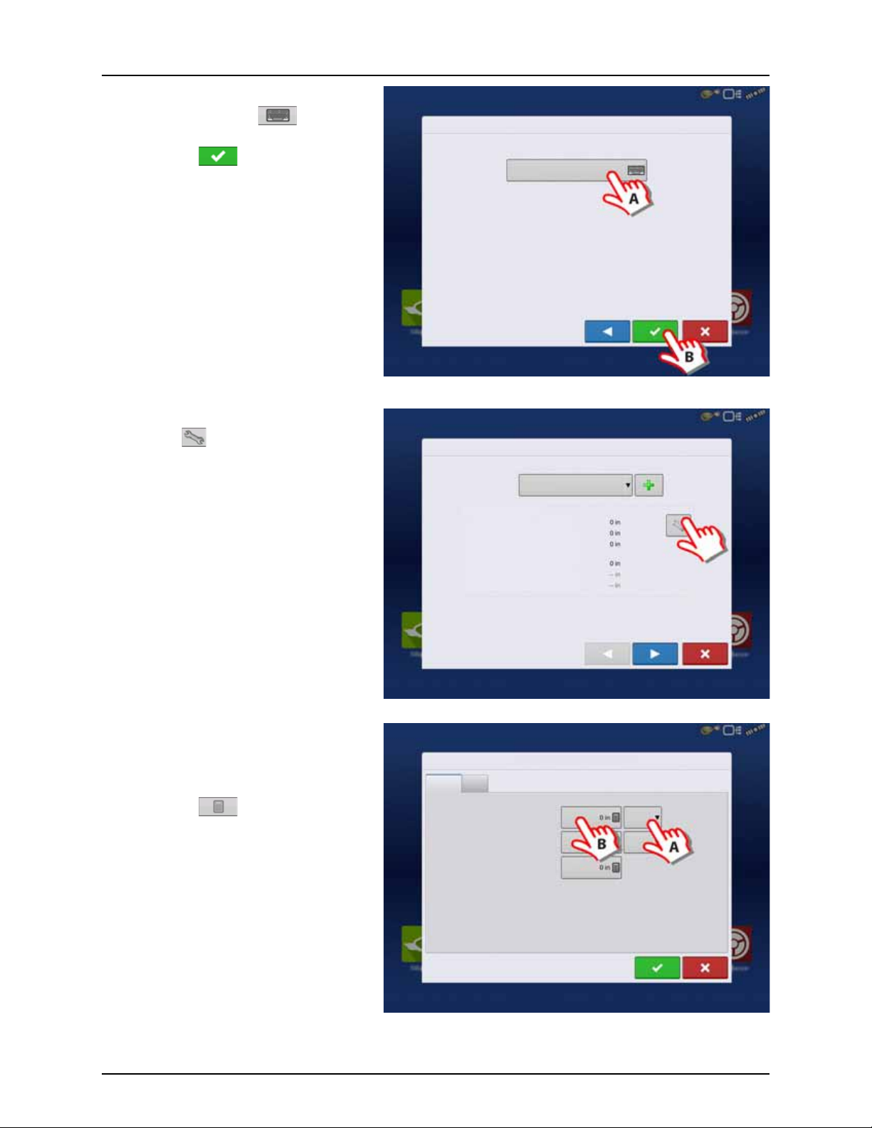
8. Vehicle Name:
Vehicle Wizard: Vehicle Name
Enter Vehicle Name
JD 4630
Operating Config uration Wizard: Vehicle
Select Vehicle
JD 4630
Offsets
Antenna Location from Rear Axle
Antenna Location from Centerline
Antenna Height from Ground
Rear Drawbar
Rear Lift Arms
Front L ift Ar ms
Vehicle Offsets: JD 4630
Antenna
Hitch
Enter Distance from Vehicle References to the Antenna
Antenna Location
from Rear Axle
Antenna Location
from Centerline
Antenna Height from
Ground
In Front
Left
A. Press the button to change the
vehicle name, if necessary.
B. Press to confirm selection.
9. Antenna Settings:
Press the button to change the antenna
settings for the Selected Vehicle in the drop
down menu.
4 - System setup
10. Enter Distance from Antenna location to Rear
Axle:
A. Choose “In Front” or “Behind” from the
Rear axle.
B. Press to type in the measured
value for the GPS Front/Back Offset
from the vehicle.
51
Page 54
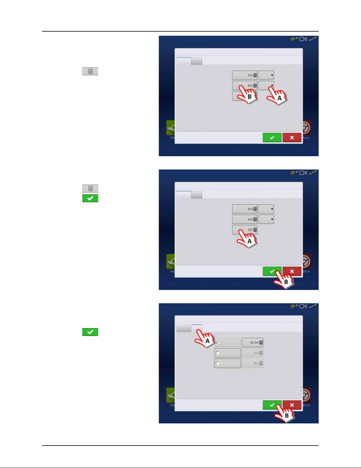
4 - System setup
Vehicle Offsets: JD 4630
Antenna
Hitch
Enter Distance from Vehicle References to the Antenna
Antenna Location
from Rear Axle
Antenna Location
from Centerline
Antenna Height from
Ground
In Front
Left
Vehicle Offsets: JD 4630
Antenna
Hitch
Enter Distance from Vehicle References to the Antenna
Antenna Location
from Rear Axle
Antenna Location
from Centerline
Antenna Height from
Ground
In Front
Left
Vehicle Offsets: JD 4630
Antenna
Hitch
Enter Distance from Rear Axle to the Following Locations
Rear Drawbar
Rear Lift Arms
Front L ift Arm s
11. Enter Distance from Antenna location to
Center line:
A. Choose “Left” or “Right” from the
Center line.
B. Press to type in value.
12. Enter Distance from Antenna Height to
Ground:
A. Press to type in value.
B. Press to confirm selection.
13. Hitch Settings:
A. Press Hitch to view data already
entered in step 7.
B. Press to confirm selection.
52
Page 55

14. Check the data in the overview.
Operating Config uration Wizard: Vehicle
Select Vehicle
JD 4630
Offsets
Antenna Location from Rear Axle
Antenna Location from Centerline
Antenna Height from Ground
Rear Drawbar
Rear Lift Arms
Front L ift Ar ms
Operating Configuration Wizard: Implement
Select Implement
Implement Wizard: Make and Model
Make
Model
Enter Implement Information
Press to confirm selection.
ATTENTION! If Offsets need to be corrected,
μ
then press the button to change the
antenna settings for the Selected Vehicle in
the drop down menu, before confirming
selection.
15. Create Implement by pressing the
button.
4 - System setup
16. Implement Information:
A. Press the “Make” to type in the
implement name.
B. Press the “Model” to type in
the implement model.
C. Press to confirm.
53
Page 56

4 - System setup
Implement Wizard: Attachment Type
Implement Attach Type
Rear Drawbar
Implement Wizard: Axle Offsets
Enter Hitch to Implement Axle Dista nce
Implement Wizard: Application Channels
Device
Application
Swath Width (ft)
Number of Sections
Capacity (gallons)
Liquid
Application
Direct
Injection
Granular
Application
Remove
Edit
Container
Liquid
17. Attachment Type:
A. Select Implement Attachment Type:
• “Rear Drawbar” for a trailer sprayer.
• “Rear Lift Arms” for a lift sprayer.
ATTENTION! The option “Front Lift Arms” is
μ
not used for HARDI® sprayers.
B. Press to confirm selection.
18. Trailer sprayer only:
A. Select to Enter Hitch to Implement
Distance:
B. Press to confirm selection.
19. Sprayer data is auto populated from the
JobCom/C2C module.
Check that Swath Width (Boom Width),
Number of Sections and Tank Capacity are
correct.
NOTE! If this screen appears blank (no text
÷
highlighted with blue) no data could be
obtained.
If the JobCom is not powered ON, then
press to cancel the setup. Power On
the JobCom and continue from step 15.
ATTENTION! The JobCom/C2C module has
μ
to be set up prior to doing this wizard. See
“Before Setup” on page 48.
Press to confirm selection.
54
Page 57

20. Additional devices:
Implement Wizard: Additional Devices
Norac UC5
OptRx Crop Sensor
Crop Sensor Settings
Sensing Width
Number of Sensors
Swath
Offsets
Note: Sensing Width should typically be set to the same
width as the implement.
Implement Wizard: Hitch Point Configuration
Enter Hitch Point Information
Implement Provides a Rear Hitch
Enter Left or Right Distance
to the left
Enter the left or right offset and the
forward or backward distance from the
point the implement connects to a vehicle
to the implement’s hitch point.
Enter Forward or Backward Distance
Implement Wizard: Implement Name
Enter Implement Name
Hardi Commander
A. Press “Norac UC5” button to enable
the use of AutoTerrain/AutoHeight.
B. Press to continue.
ATTENTION! If the “Norac UC5” is not
μ
enabled, the AutoTerrain/AutoHeight will
not be shown in the working screen.
21. Press to continue.
ATTENTION! Settings here are not relevant
μ
for HARDI® Trailer and Lift sprayers!
4 - System setup
22. Enter Implement Name:
A. Press button to change name.
B. Press to confirm name.
55
Page 58
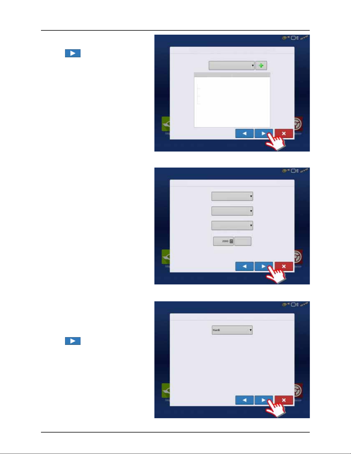
4 - System setup
Operating Configuration Wizard: Implement
Select Implement
Hardi Commander
Equipment Name
Implement Hardi Commander
Device
Container
Device
Hardi
Main Tank
Boom Height
Operating Configuration Wizard: Speed Source
Primar y Source
Backup Source
Auxiliary Device Channel
Auxiliary Channel Calibration
Calibrate
Distance
Pulses / 100 ft
Display GPS
Auxiliary Device
Radar
Operating Configuration Wizard: Speed Source
Primar y Source
23. Select the specific implement to be setup in
the pull down menu.
Press to confirm the selection.
24. Select Primary Speed Source.
• Trailer sprayer with SafeTrack/IntelliTrack:
Must always use “Hardi” as speed source as
the steering system cannot use GPS as
speed source.
• Lift mounted sprayer:
Can select between “Display GPS” or
“Auxiliary Device” as speed source.
NOTE! If “Display GPS” is selected, the Hardi
÷
option must be selected as backup source.
ATTENTION! For additional information see
μ
“Speed Input Settings” on page 89.
25. “Hardi” is now selected as Primary Source.
ATTENTION! No other source can be
μ
selected when Hardi is selected as primary
source.
Press to confirm the selection.
56
Page 59
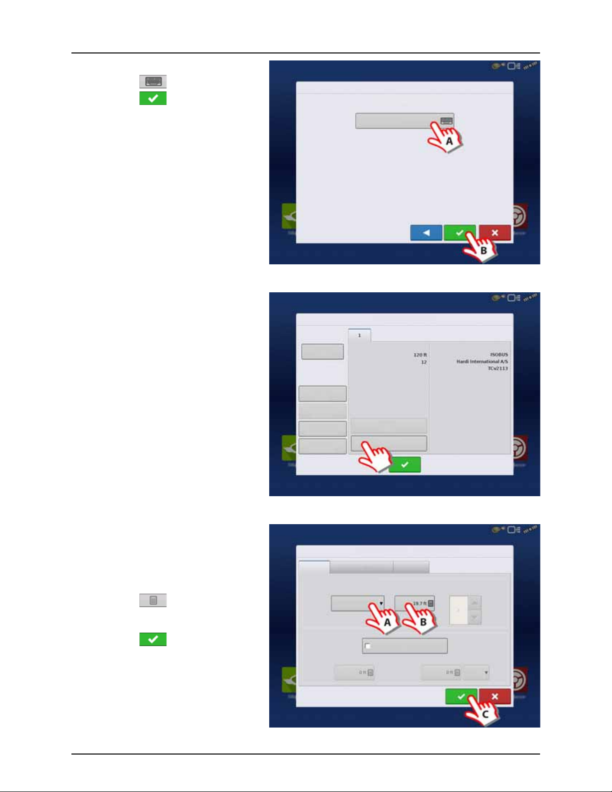
26. Suggested Name for Configuration:
Operating Configuration Wizard: Configuration Name
Suggested Name for Configuration
JD 6430, Hardi Commander
Configuration Setup
Vehic le
JD 4630
Vehicle
Offsets
Norac
UC5
Speed
Input
Auxiliary
Input
Automatic
Swath Control
Equipment
Settings
Offsets
Implement: Hardi Commander Controller: Hardi IS OBUS
Full Swath:
Sections:
Device:
Make:
Structure Label:
Implement Offsets: Hardi Commander
Implement Liquid with Hardi Sprayer
Implement Modeling
Implement Provides a Rear Hitch
Hitch to Axle
Distance
Lateral Offset from Centerline
Left
Implement Type
Hardi SafeTrack
Front Hitch to Rear Hitch
Implement Rear Hitch
Heading
Aggressivene ss
Boom Height
A. Press button to change name.
B. Press to confirm selection.
27. Trailer sprayers only:
Press “Offsets” to edit the configuration.
4 - System setup
28. Trailer sprayers only:
A. If applicable, select “Hardi SafeTrack”
as implement Type.
ATTENTION! For IntelliTrack sprayers, select
μ
the “Hardi SafeTrack” option.
B. Press to type in the measured
distance from Hitch to the axle of the
sprayer.
C. Press to confirm.
57
Page 60

4 - System setup
Configuration Setup
Vehic le
JD 4630
Vehicle
Offsets
Norac
UC5
Speed
Input
Auxiliary
Input
Automatic
Swath Control
Equipment
Settings
Offsets
Implement: Hardi Commander Controller: Hardi IS OBUS
Full Swath:
Sections:
Device:
Make:
Structure Label:
Look-Ahead
Settings
Automatic Swath Control
Application
Outside Boundary Option
Keep Unchanged
Turn S ectio n Off
Minimize Skip
Minimize Overlap
User Defined
Coverage Option
Planting
29. Press “Automatic Swath Control” to edit the
configuration.
30. Automatic Swath Control options:
• Outside Boundary Option
Select one of the two options to determine system behavior when a section exits a field boundary.
• Coverage Option
In the Coverage Option area, you must choose between three options:
• Minimize Skip
Turns off the implement section after the entire section is fully inside your coverage area.
This prevents the possibility of skips.
• Minimize Overlap
Turns off the implement section when that section first enters your coverage area.
This prevents the possibility of overlaps.
• User Defined
Allows you to choose what percentage of the implement section is within the coverage area before that section
turns off. For example, if you choose 50%, then the section will switch off when half of it is within your coverage
area.
• Press “Look Ahead Settings” to edit settings.
58
Page 61

31. Look Ahead settings:
Turn- On:
Turn- Off :
Look Ahead Settings
Configuration Setup
Configuration Product
Equipment
Application
JD 4630, Hardi Commander
Equipment Name
Vehicle JD 4630
Implement Hardi Commander
Device
Container
Device
Hardi
Main Tank
Boom Height
• Turn-On Look Ahead
Determines how far ahead the system looks
to turn the sections back on. This
compensates for delay in the system when
the sprayer sections are turned on.
Hardi default value: 1.0 second.
• Turn-Off Look Ahead
Determines how far ahead the system looks
to turn the sections off. This compensates for
delay in the system when the sections are
turned off.
Hardi default value: 0.5 second.
Press to confirm.
32. Overview of Configuration Setup with a
Trailed sprayer as example:
Vehicle: JD 4630.
Implement: Hardi Commander.
• Device: Hardi
• Container: Main Tank
• Device: Boom Height
4 - System setup
33. W hen ret urned to Co nfig uration Setup screen, then press in o rder to continue w ith “ Product setup” on pag e 68.
59
Page 62
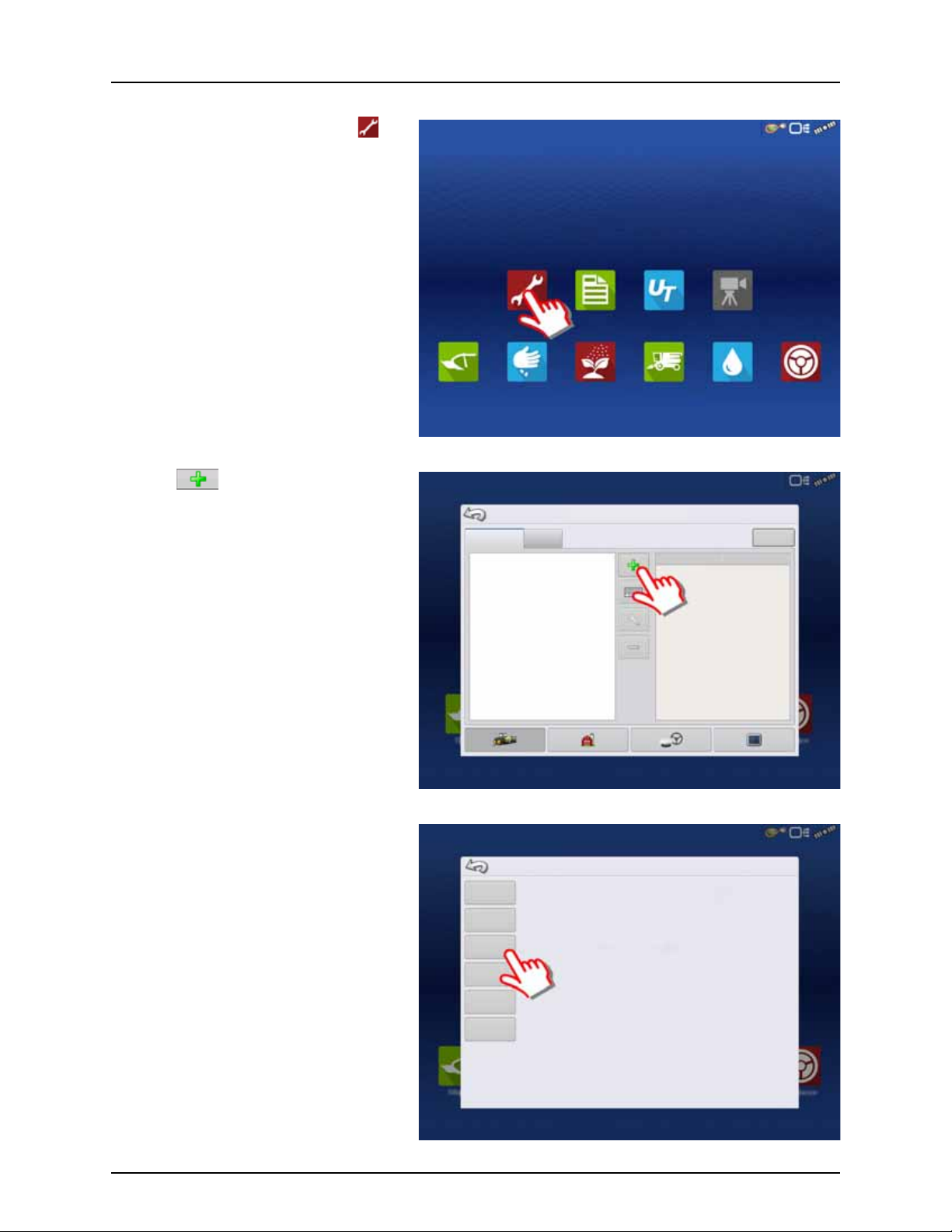
4 - System setup
Summary Universal
Ter mi na l
Camera
Tillage Planting Application Harvest Water
Management
Guidance
Configuration
Configuration Setup
Product
Equipment
Equipment
Name
Tillage
Planting
Create a planting operating configuration.
Application
Harvest
Create a tillage operating configuration for coverage logging and guidance-only
operations.
Create a liquid and granular application, or strip-till operating configuration.
harvest grain yield monitoring operating configuration.
Choose Operating Configuration Type
Surveying Create a surveying operating configuration to record ground elevation.
Tilling Create a tilling operating configuration for use with I ntellislope.
Configuration for Self-Propelled sprayers
1. At the HC 9600 Home Screen, press to
enter the Configuration Setup.
2. Press to add a Configuration.
3. Press “Application” to create an application
setup.
60
Page 63
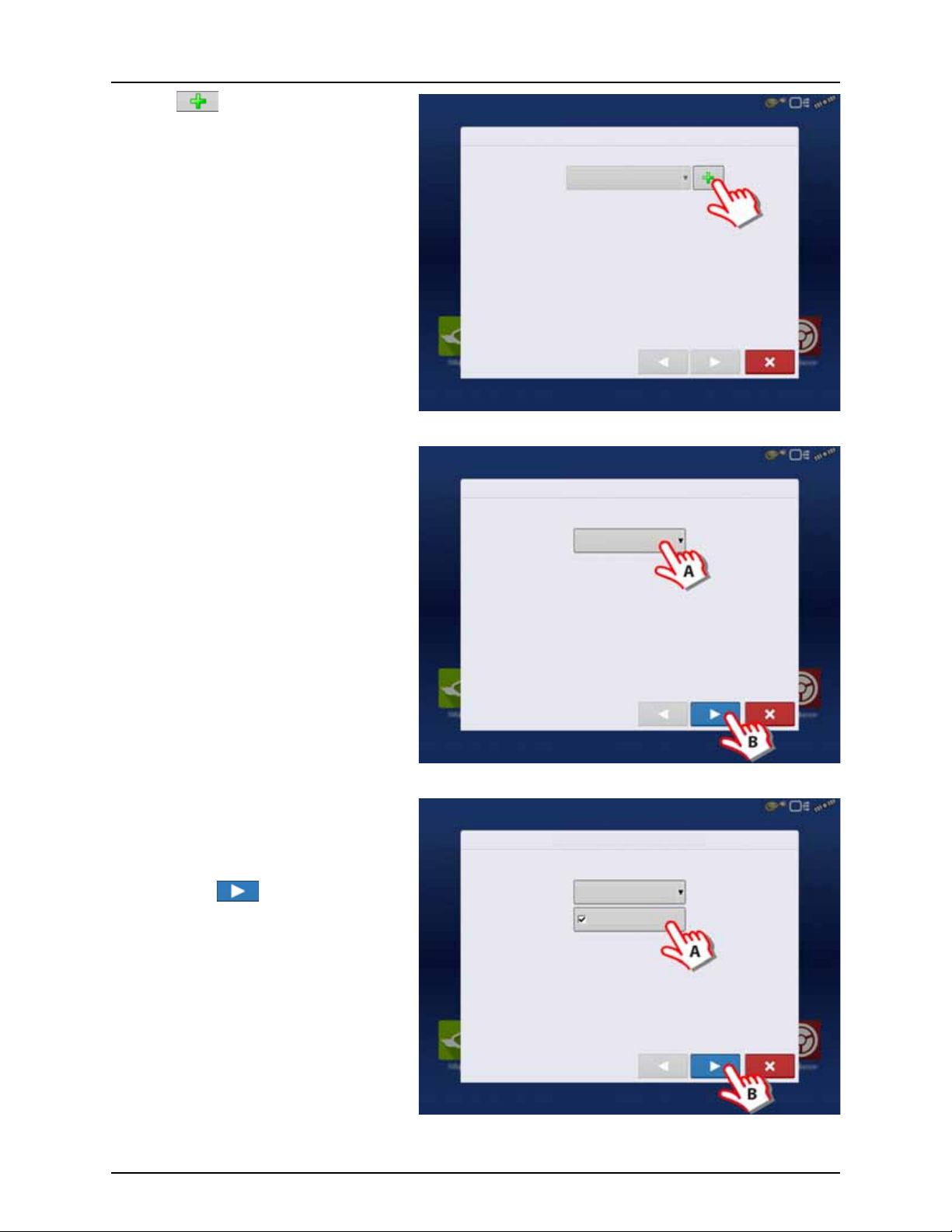
4. Press to select a vehicle.
Operating Configuration Wizard: Vehicle
Select Vehicle
Vehi cle Wizar d: Veh icl e Type
Create New Vehicle
Vehicle Type
Self-Propelled Applicator
Vehi cle Wizar d: Veh icl e Type
Create New Vehicle
Vehicle Type
Self-Propelled Applicator
All-Wheel Steer
5. Select “Self-Propelled Applicator”.
4 - System setup
6. When Self-Propelled Applicator is selected:
A. Check this box if All-Wheel Steer is
applicable and will be used when
spraying.
B. Press to confirm.
ATTENTION! Checking the “All-Wheel Steer”
μ
option activates logging of 4 wheel steering
for AutoSectionControl.
61
Page 64

4 - System setup
Vehicle Wizard: Make and Model
Make
Model
Enter Vehicle Information
Implement Wizard: Application Channels
Device
Application
Swath Width (ft)
Number of Sections
Capacity (gallons)
Liquid
Application
Direct
Injection
Granular
Application
Remove
Edit
Container
Liquid
Implement Wizard: Additional Devices
Norac UC5
OptRx Crop Sensor
Crop Sensor Settings
Sensing Width
Number of Sensors
Swath
Offsets
Note: Sensing Width should typically be set to the same
width as the implement.
7. Enter Vehicle Information:
A. Press the “Make” to type in the
vehicle name.
B. Press the “Model” to type in
the vehicle model.
C. Press to confirm.
8. Sprayer data is auto populated from the
JobCom/C2C module.
Check that Swath Width (Boom Width),
Number of Sections and Tank Capacity are
correct.
NOTE! If this screen appear blank (no text
÷
highlighted with blue) no data could be
obtained.
If the JobCom is not powered ON, then
press to cancel the setup. Power On
the JobCom and continue from step 5.
ATTENTION! The JobCom/C2C module has
μ
to be set up prior to doing this wizard. See
“Before Setup” on page 48.
Press to confirm selection.
9. Additional devices:
A. Press “Norac UC5” button to enable
the use of AutoTerrain/AutoHeight.
B. Press to continue.
ATTENTION! If the “Norac UC5” is not
μ
enabled, the AutoTerrain/AutoHeight will
not be shown in the working screen.
62
Page 65

10. Enter Vehicle Name:
Vehicle Wizard: Vehicle Name
Enter Vehicle Name
ALPHA evo
Operating Configuration Wizard: Vehicle
Select Vehicle
Offsets
Antenna Location from Rear Axle
Antenna Location from Centerline
Antenna Height from Ground
Dispensing Location from Rear Axle
Dispensing Location from Centerline
Behind
Vehicle Offsets: Saritor 5000
Antenna
Steering
Enter Distance from Vehicle References to the Antenna
Antenna Location
from Rear Axle
Antenna Location
from Centerline
Antenna Height from
Ground
In Front
Left
A. Press button to change name.
B. Press to confirm name.
11. Press to enter values for Antenna Offsets.
4 - System setup
12. Vehicle Offsets:
A. Press to enter Antenna Location from
Rear Axle.
B. Select if the Antenna is In Front or
Behind the Rear Axle.
C. Press to enter Antenna Location from
the sprayer’s center line.
D. Select if the Antenna is to the Left or
Right of the sprayer’s center line.
E. Press to enter Antenna Height from
Ground.
F. Press “Steering” to continue with
Steering Type selection.
63
Page 66

4 - System setup
Vehicle Offsets: ALPHA evo
Antenna
Steering
All Wheels
Steering Type
Operating Configuration Wizard: Vehicle
Select Vehicle
Offsets
Antenna Location from Rear Axle
Antenna Location from Centerline
Antenna Height from Ground
Dispensing Location from Rear Axle
Dispensing Location from Centerline
Behind
Operating Configuration Wizard: Speed Source
Primar y Source
Backup Source
Auxiliary Device Channel
Auxiliary Channel Calibration
Calibrate
Distance
Pulses / 100 ft
Display GPS
Auxiliary Device
Radar
13. Steering Type:
A. Press to select steering method to be
used when spraying:
“All Wheels” or “Front Wheels”.
B. Press to confirm selections.
14. Press to confirm the settings and
continue.
15. Select Primary Speed Source.
• Self-Propelled sprayer:
Can select between “Hardi” or “Display GPS”
as speed source.
• SARITOR sprayer only:
Always select “Display GPS” as speed source.
NOTE! If “Display GPS” is selected, the Hardi
÷
option must be selected as backup source.
ATTENTION! For additional information see
μ
“Speed Input Settings” on page 89.
64
Page 67

16. When “Hardi” is selected as Primary Source.
Operating Configuration Wizard: Speed Source
Primar y Source
Operating Configuration Wizard: Configuration Name
Suggested Name for Configuration
Saritor 5000
Configuration Setup
Vehic le
JD 4630
Vehicle
Offsets
Norac
UC5
Speed
Input
Auxiliary
Input
Automatic
Swath Control
Equipment
Settings
Offsets
Implement: Hardi Commander Controller: Hardi IS OBUS
Full Swath:
Sections:
Device:
Make:
Structure Label:
ATTENTION! No other source can be
μ
selected when Hardi is selected as primary
source.
Press to confirm the selection.
17. Suggested Name for Configuration:
A. Press button to change name.
B. Press to confirm selection.
4 - System setup
18. Press “Automatic Swath Control” to edit the
configuration.
65
Page 68

4 - System setup
Look-Ahead
Settings
Automatic Swath Control
Application
Outside Boundary Option
Keep Unchanged
Turn S ectio n Off
Minimize Skip
Minimize Overlap
User Defined
Coverage Option
Planting
19. Automatic Swath Control options:
• Outside Boundary Option
Select one of the two options to determine system behavior when a section exits a field boundary.
• Coverage Option
In the Coverage Option area, you must choose between three options:
• Minimize Skip
Turns off the implement section after the entire section is fully inside your coverage area.
This prevents the possibility of skips.
• Minimize Overlap
Turns off the implement section when that section first enters your coverage area.
This prevents the possibility of overlaps.
• User Defined
Allows you to choose what percentage of the implement section is within the coverage area before that section
turns off. For example, if you choose 50%, then the section will switch off when half of it is within your coverage
area.
• Press “Look Ahead Settings” to edit settings.
66
Page 69

20. Look Ahead settings:
Turn- On:
Turn- Off :
Look Ahead Settings
Configuration Setup
Configuration Product
Equipment
Application
Saritor 5000
Equipment Name
Vehicle Saritor 5000
Device
Container
Device
Hardi
1300
Boom Height
• Turn-On Look Ahead
Determines how far ahead the system looks
to turn the sections back on. This
compensates for delay in the system when
the sprayer sections are turned on.
• Turn-Off Look Ahead
Determines how far ahead the system looks
to turn the sections off. This compensates for
delay in the system when the sections are
turned off.
Press to confirm.
21. Overview of Configuration Setup:
Vehicle: Saritor 5000
• Device: Hardi
• Container: 1300
• Device: Boom Height
4 - System setup
μ
22. W hen ret urned to Co nfig uration Setup screen, then press in o rder to continue w ith “ Product setup” on pag e 68.
ATTENTION! A Self-Propelled sprayer will
have no implement information.
67
Page 70

4 - System setup
Configuration Setup
Configuration Product
Equipment
Add Product
Seed
Vari ety
Application
Product
Mix/Blend
Harvest
Product
Create a seed product to be planted.
Create a single product to be added to a tank mix or to be applied by itself.
Tank Mix or Dry Blend of two or more products.
Create a new harvest product.
Product Setup Wizard: Product Type
Product Type
Ferti lizer
Ferti lizer
Anhydrous Ammonia
Product setup
1. At “Configuration Setup” screen:
A. Select the Product tab to create a
product.
B. Press to add a product.
2. Select “Application Product” to create a
single product or a carrier.
μ
ATTENTION! This example will show setup
with Water as Carrier.
3. Press the drop down menu to select Carrier
as Product Type.
68
Page 71

4. Carrier drop down menu:
Product Setup Wizard: Product Type
Product Type
Carrier
Carrier
Water
Product Setup Wizard: Units
Select Product Units
Units
ounces (fluid)
Product Setup Wizard: Product Name
Product Name
Water
A. Select Water as Carrier.
B. Press to confirm the selection.
5. Select Product Units:
A. Select ounces as units.
B. Press to confirm the selection.
4 - System setup
6. Product Name:
A. Press to change Product
Name.
B. Press to confirm Product
Name.
NOTE! This step is not possible when setting
÷
up water as Carrier.
69
Page 72

4 - System setup
Configuration Setup
Configuration Product
Equipment
Application
Water
Manufacturer:
Type:
Units:
Restricted Use:
EPA Number:
Carrier
ounces (fluid)
No
Wate r
General Rate Legend
Produc t Units
ounces (fluid)
None
Manufacturer
EPA Number
Restricted Use Pesticide
Wate r
Attribute: Rate
Average
Range Spacing
Color Scheme
Green
Reset to Default
Legend
Ranges
General Rate Legend
7. Application Water is now created.
To edit the Legend Settings:
A. Mark the product.
B. Press .
8. Configuration Setup window opens at
“General” tab.
Press “Rate Legend” tab to setup Legends.
SETUP COMPLETED
μ
70
9. The Legend Settings can be edited as
necessary.
Press to confirm and continue.
ATTENTION! When the complete Quick Setup Guide has been completed, the controller is ready for use in the field.
Refer to “Setup Event” on page 156 for instructions on how to begin a field operation.
Page 73

Configuration
Configuration Product
Equipment
Varie ty 1
Varie ty 2
Application
Grain Harvest
Corn
Setup buttons
The Setup buttons shown at the bottom of the
Setup screens, are where you can toggle between
screens that adjust settings for Configuration,
Management, GPS and display.
Configuration button.
Press to adjust the configuration settings
particular to your vehicle and equipment; as
well as enter and edit product information.
For more information, see “Product tab” on
page 72, as well as “Configuration Setup
Screen” on page 151.
Management button.
4 - System setup
Press to access and edit Grower, Farm, Field and Operator information. For more information, see “Management
button” on page 74.
GPS button.
Press to adjust Guidance settings, GPS settings, and lightbar settings. For more information, see “GPS
Guidance/Steering Control” on page 93.
Display button.
Press to adjust settings for Time and Date, brightness and volume settings, operating units, language, enable video,
view features, and also create and restore backups.
71
Page 74
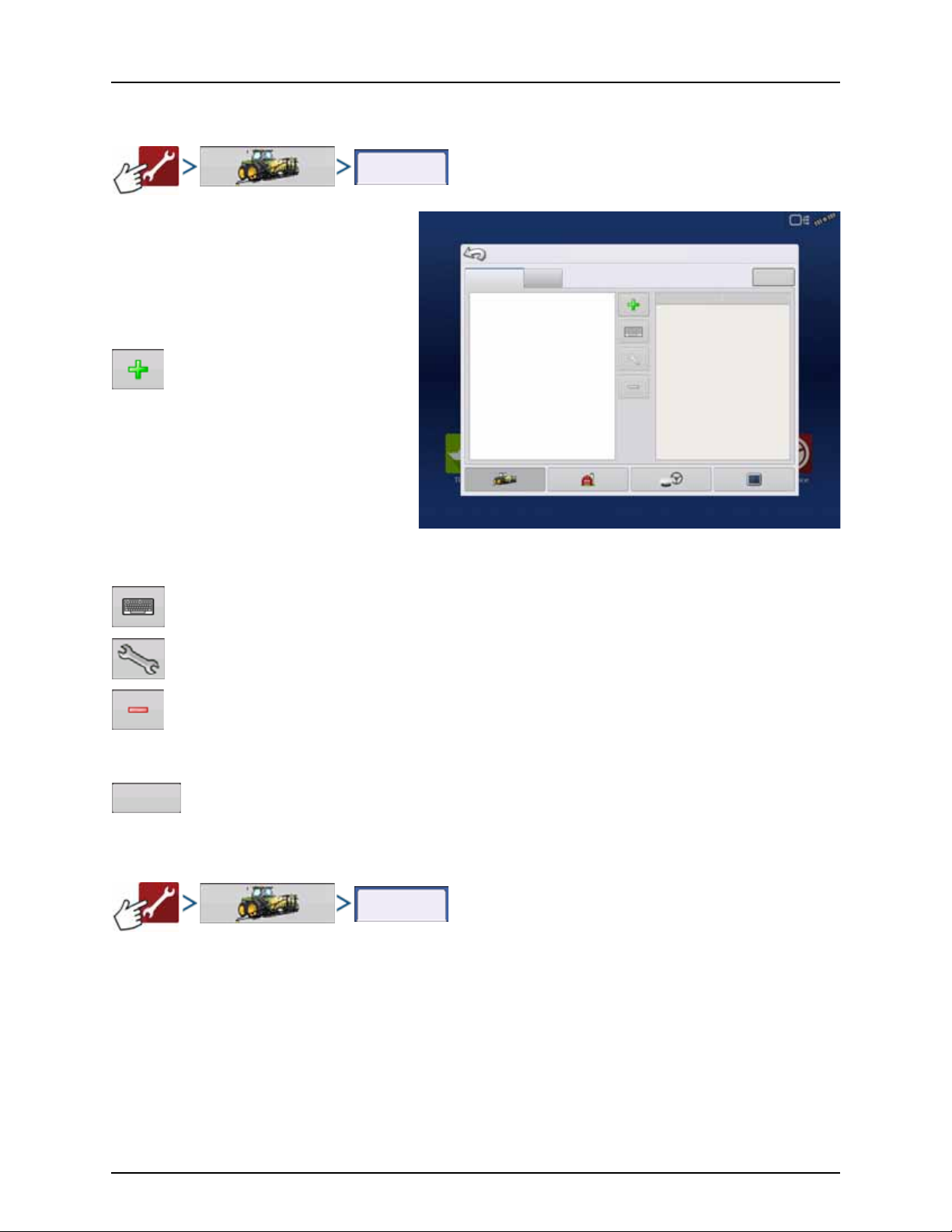
4 - System setup
Configuration
Configuration
Configuration Setup
Product
Equipment
Equipment
Name
Equipment
Product
Equipment Setup
Configuration tab
The Configuration tab is where you can create,
view and change configuration settings.
An operating configuration is a task-specific
association of vehicle, implement, controller, and
speed source that is saved for use over different
seasons and on different displays.
Press to add an operating configuration.
A wizard takes you through the process
of creating a configuration.
• When finished, the new configuration
appears in the list on the left side of the
screen.
• When you highlight the configuration, the
equipment in the configuration are listed in
the box on the right side of the screen.
NOTE! Information regarding configurations for specific operations is given in each operation’s feature user guide.
÷
Press to rename the configuration.
Press to adjust configuration settings.
Press to remove a configuration.
WARNING! When you remove a configuration, all data logged with that configuration will also be removed!
±
Press to add, edit, or remove information for a specific vehicle, implement or controller.
Product tab
72
Page 75
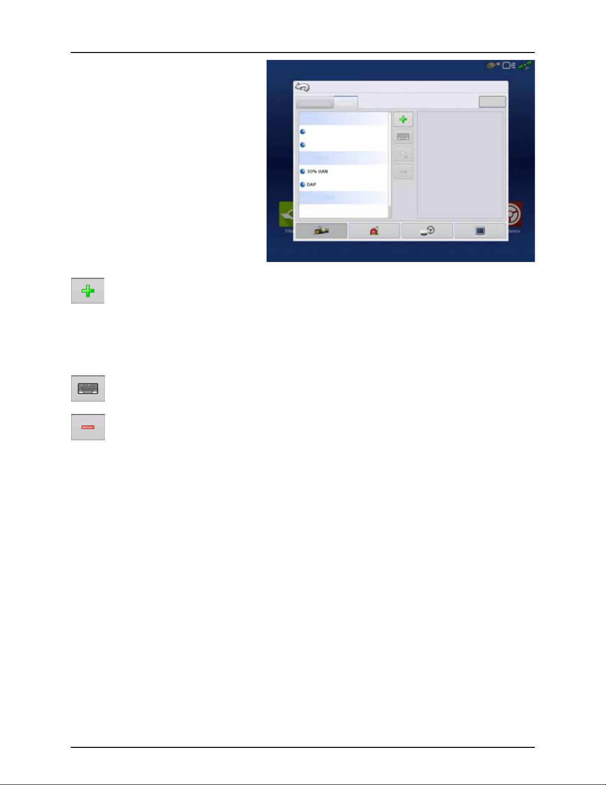
4 - System setup
Configuration Setup
Configuration Product
Equipment
Planting
Varie ty 1
Varie ty 2
Application
Grain Harvest
Corn
The Product tab is where you can perform the
following tasks:
• Add or import Planting products.
• Add or import Application products.
• Add Application Product mixes (such as a
tank mix, or a dry blend of multiple products).
• Add or import Harvest products.
Add button
Press to add or import a Product. At the following screen, choose a Product Option: Add Product, Import Product,
or Add Product Mix (if in Application). From here, an on-screen wizard guides you through each step of the setup
process.
• When finished, the new product appears in Product Tab.
• When you highlight the product, information about the product appears on the right side of the screen.
• Specific planting and application product information can be viewed in those respective chapters.
÷
Application Settings
Edit Info button Press to edit the following information for the highlighted product in the Product List.
Edit Legend button
For more information, see “Legend Settings” on page 151.
Press to rename the product.
Press to remove a product.
NOTE! When you remove a product, all regions using that product will also be removed!
• Product Units
• Manufacturer
• EPA Number
• Check box for restricted use pesticides
Press to change the legend settings listed below.
• Average
• Range Spacing
• Color Scheme
• Ranges
• Reset to Default Legend
73
Page 76

4 - System setup
Grower/Farm/Field
Grower/Farm/field Season Operator
Grower: Gene Eilers
Farm : Shel don
Field: Creek Bottom 30
Field: E ast 80
Field: N eighbor’s H ouse
Field: N orth 40
28 acTrue A rea:
Boundary
28.10 ac
Clear
Management Setup
Businesses
Management button
The Management tabs, which are accessible from the Management button on the Setup screen, include Grower/Farm/Field,
Season, and Operator.
Grower/Farm/Field tab
Grower
The Grower refers to the business or person that the system is in operation for. Contact information can also be entered for
each Grower. The Grower information will be passed into mapping software for automatic Grower setup within desktop
software.
Press to add a Grower.
Edit an existing name of a Grower by highlighting that name and pressing button.
Press to enter information for the Grower’s Name, Tax ID and Memo.
Press to remove a Grower.
NOTE! Personal Information entered at this screen can be added or edited at any time.
÷
Farm and Field
In the display, farms are subdivided into fields. You can associate Field names with a particular Grower. If the display will be
used for multiple Growers, enter each Grower business name and associate the field names with the correct grower when
the fields are set up within the system.
In the Field Tab, select a Grower underneath the
drop-down menu at the top. Each farm of that
particular grower is shown in a list, with the fields
within that farm as sub components within that
list.
Press to add a Field.
Edit an existing name of a Field by
highlighting that name and pressing
button.
Press to remove a Field.
Edit the Farm and Field information by highlighting that name and pressing button.
74
Page 77
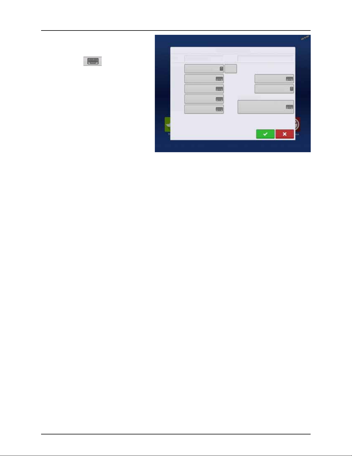
The Field Information screen opens, showing the
Field Information
Field Creek Bottom 30
Farm Shel don
Clear
Bounds
Area
County
Town sh ip
Range
Section
FSA Number
FSA Area
Legal De scription
98.64 ac
98.64 ac
name of that field in the “Field” title bar.
Field Name information that can be added or
edited by pressing .
Possible to edit:
• County
• Tow ns hi p
• Range
• Section Number
• Legal Description
• Area
Shown in the total acres (hectares) of the
field. Used to calculate area remaining in
field.
• FSA Number
Refers to the U.S. Farm Service Agency’s four-digit number assigned to every field.
• FSA Area
Refers to tillable acres as established by the FSA.
• Clear Bounds button
Press to center the map on the current GPS position.
4 - System setup
÷
NOTE! The Clear Bounds feature is particularly useful if you have flyer points or have logged a point outside the
mappable range of your current location.
75
Page 78
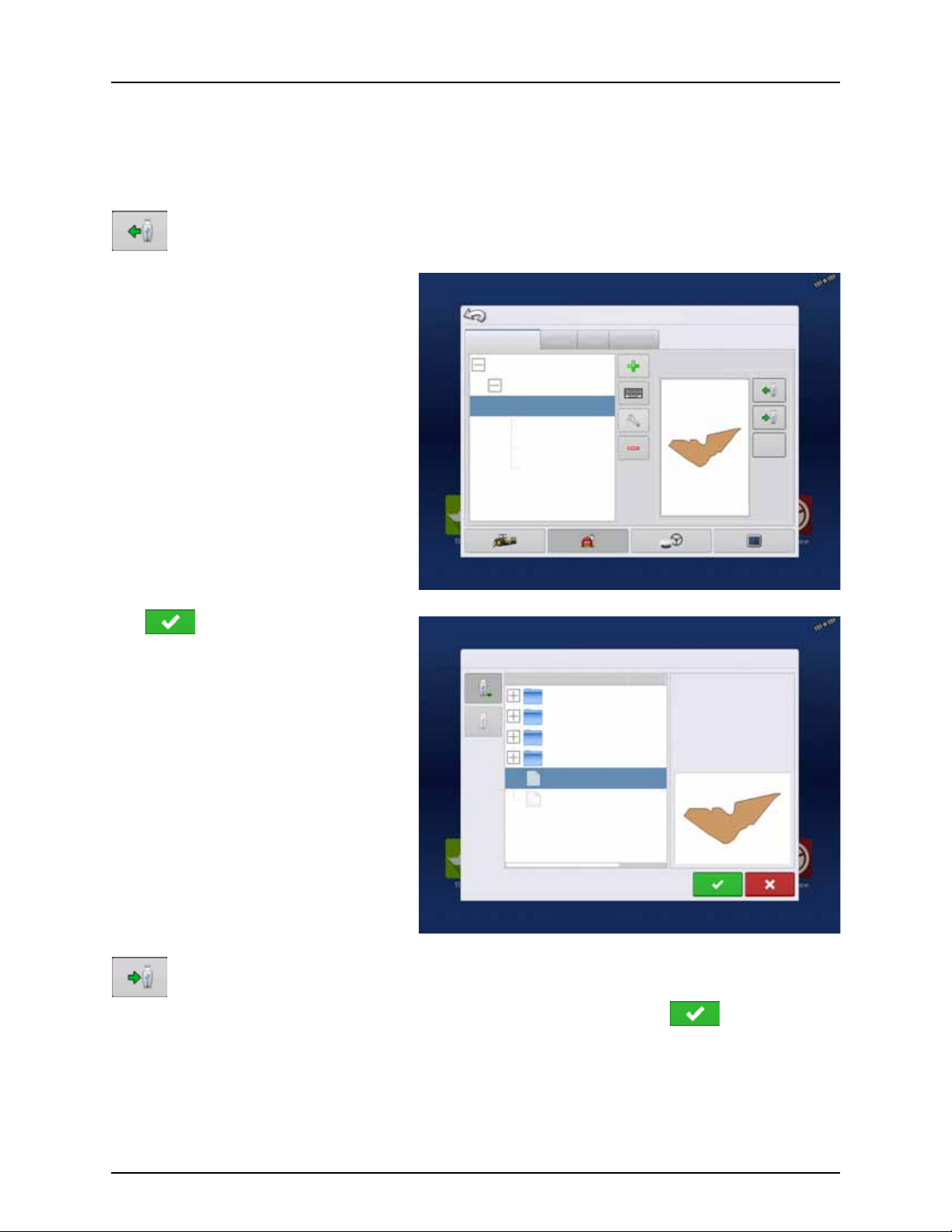
4 - System setup
Grower/Farm/field Season Users
Grower: Gene Eilers
Farm : Shel don
Field : Low 80
Field: High 90
98 acTrue Area :
Boundary
98.64 ac
Clear
Management Setup
Businesses
File Selection
Field:
Farm :
Grower:
Demo
Allegon County
Michigan Test Fields
Field_2. iby
Boundaries
Display Backups
irx_multi_produc t
Irx_single_product
226.13 ac
Field_1. iby
Importing and Exporting Field Boundaries
Boundaries can be created with the display or imported from desktop GIS software. Any boundary files present in the display
can also be exported for use in desktop mapping software.
NOTE! For more information on creating boundaries, see “Create Boundary” on page 154.
÷
To import a boundary from the USB drive, first go to the Setup Field tab, highlight the correct field in the
Farm/Field list and press the USB Import button.
The File Selection screen appears. Highlight the
desired file to import.
Operator can import/export all fields and
boundaries at once with an .AGSETUP file. For
more information on .AGSETUP files see
“.AGSETUP” on page 198.
Press to complete the import process.
To export a boundary to the USB drive, highlight the correct field in the Farm/Field list and press the USB Export
button. At the File Selection screen, highlight the desired field to export.
A screen will appear telling you that the boundary was exported successfully. Press return to the field
setup screen.
76
Page 79
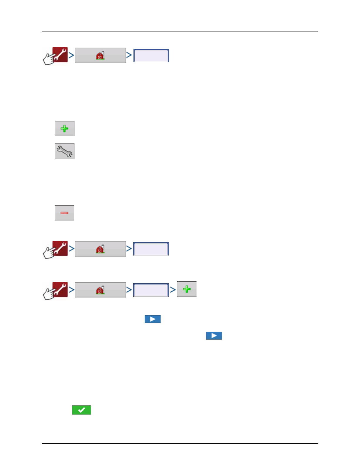
4 - System setup
Season
Users
Users
Season tab
A season is defined as the calendar year that the crop will be harvested. A season has a start and an end date. Creating a
season and setting it to active is required prior to the system logging any data.
The seasons are displayed in lists, with the Active season displayed in bold face type. All new data is logged to the active
season; therefore a season must be set as Active before you can log any new data to it.
If a user would like to remove logged data from the display, they can delete a season from the display. Before deleting a
Season, make sure that all logged data has been properly archived within management software or AgFiniti Mobile.
• Press to add a Season.
• Edit an existing name of a Season by highlighting that name and pressing button.
• Set Active button.
Press to set the season selected in the Summary list box to the active season.
• Season Reminder button.
Press to set the date that the system will prompt the operator to create a new season.
• Press to remove a season.
Users tab
User tab allows user to add, modify, or delete users from the display.
Add a user
1. Enter first name and/or last name (must enter a first or last name, entering both recommended).
2. Enter applicator license (optional). Press to continue.
3. Select Operator or Manager (can select either, none, or both). For more information on selecting Operator/Manager
and setting up permissions, see “Permissions tab” on page 78. Press to continue.
4. Enter and verify password (optional).
• Locks the display’s ability to load/change operating configurations, access setup and USB, if Manager has a
password set.
• Leaves display unsecured unless each manager sets a password.
• Warning message appears if passwords do not match.
• No restriction for password format (can be any combination of letters, numbers, and special characters).
• Case sensitive.
5. 5. Press to accept.
77
Page 80

4 - System setup
Users
Select Specific
User
Edit User
General Phone/Email Address Permissions
Home Phone
Mobile Phone
Business Phone
Home Email
Business Email
Full permission provides this user access to all
unlocked features and functionality.
Full
Operator
Manager
User Role
Permission Level
General Phone/Email Address Permissions
Edit User
Edit User Profile
“Edit User” screen allows user to edit information originally entered when profile was added. It also allows access to more
information, such as Phone/Email, Address and Permissions.
General tab
• First and Last Name
• Set and Clear Password
• Applicator License
• Memo
Phone/Email tab
• Home Phone
• Mobile Phone
• Business Phone
• Home Email
• Business Email
Address tab
• Address
• Extended Address
• City/Locality
• State/Province
• Country
• Postal Code
Permissions tab
This is an optional function that defines what access the user will have in the display. Users are defined as Operator or
Manager (can select either, none, or both).
Operators
• Have full or limited access
• No access to USB or Setup options, unless
also set as a Manager
Can import from USB from Map Screen (RX,
patterns, boundaries)
• Manager sets up privileges
Managers
• Full access to the display settings and
• Only user that can change the selected
• Ability to log out of the display
System can be set up with operators only.
Passwords are not used when set up this way.
functions
configuration
78
Page 81

Permission Level for Operators
General Phone/Email Address Permissions
Operator
Manager
User Role
Permis sions Leve l
Custom
Management
Mapping
Patterns
Field Management
View Summary
Pan/Zoom Controls
Legend Toolbox
Boundary Toolbox
Guidance Toolbox
Minimize Toolboxes
Straight AB
SmartPath
Pivot
Adaptive Cur ve
Identical Curve
A+ Heading
Traml ines
Nudge
Shift
Remove Patterns
Edit User
Management
Field Management
View Summary
Management
Field Management
View Summary
Full Permission
Provides full access to features and functionality on the map and home screen. A user, set only as an Operator, cannot select
a different configuration and cannot access data transfer or Setup, when a manager is setup in the display.
Basic Permission
No access to:
• Summary screen
• Legend Tab on Map screen
• Marks Tab on Map screen
• Boundary Tab on Map screen
Limits Guidance options to:
• Creating & loading Straight AB or SmartPath patterns
• Nudge
• Remark A
• Save or reset guidance line
Custom Permission
Can allow or deny the following options:
• Management screen
• Pan/Zoom controls
• Legend Toolbox
• Marks Toolbox
• Boundary Toolbox
• Guidance Toolbox
• Minimize Toolbox
• Each individual guidance pattern
• Ability to remove guidance patterns
4 - System setup
Display uses Traditional mode when Field
Management is checked. Events using the
Traditional mode are tied to the
Grower/Farm/Field structure.
Display uses Events Only mode when Field
management is unchecked.
79
Page 82

4 - System setup
GNSS
CAN
Gene Eilers
Data Transfer
Remote Support
Setup Summary Universal
Ter mi na l
Camera
Tillage Planting Application Harvest Water
Management
Guidance
New
Patte rn
Load
Patter n
Manage
Patte rns
Guidance
The Home and Map screen will appear different
depending on how you assigned user permissions.
For setting up users with permissions, see “Users
tab” on page 77.
Basic Permissions - Home screen
• Summary screen locked.
• Setup and Data Transfer buttons are locked
(as indicated by a padlock icon on those
buttons).
• Brightness and volume are on home screen settings saved per operator.
• Operator Change - Option to continue or
start new operation when operators change.
Full Permissions - Home Screen
• Summary screen button is accessible.
• Setup and Data Transfer are locked.
• A manager can access these buttons by pressing the button and inputting their password.
• Configuration is locked when field operation is started.
Basic permission - Map screen
Operator can:
• Create guidance lines
• Straight AB
• SmartPath
• Nudge
• Guidance setup
80
Page 83

Accessing Setup Menus
1. Press button.
2. Select Manager from drop-down menu. Press .
3. Enter password. Press .
Password gives complete access to the setup menus:
• Configurations Settings
• Grower management
• GPS settings
• Display settings
Do not have to be a Manager to create certain objects:
• Grower
• Far m
• Field
• Product (can't change units)
4 - System setup
81
Page 84

4 - System setup
Data Transfer
Accessing Data Transfer
Data Transfer
A. Select Manager from drop-down menu. Press .
B. Enter password. Press .
Password gives complete access to the USB functions:
• Networking
• AgFiniti Login
• Import/export
• AgSetup files
• Export data
• Upgrade firmware
• Advanced options
Advanced Options with USB
• Ability to create/restore backups from USB
• Options for exporting log files
• Export by grower
• Export data at shutdown
• Export all log files
82
Page 85

4 - System setup
Release:
Serial Number:
Hardware ID:
Hardware Rev:
DISPLAY
CAN A
CAN B
Devices
Diagnostics
Application:
Branch:
Build:
Schema:
Interchange:
Database:
File Form at:
Run Time:
Boot Counter:
Businesses
Forgotten Passwords
When a Manager forgets his password, he won't be able to access Setup.
Tech Support will be able to generate a password based on the serial number and firmware of the monitor.
Password generator will require the following
information:
A. Display serial number
B. Major revision
• First digit of firmware version.
C. Minor revision
• First digit of firmware version after
decimal.
Example
A. Version 5.4
B. Major = 5
C. Minor = 4
Only needed when a Manager forgets their
password and works within the display until
firmware is upgraded.
How will Tech Support identify if the person calling in is a Manager or not?
They will ask the caller, “Are you a Manager in the display?” If the customer answers yes, Tech Support will generate the
password. If the customer answers no, Tech Support will require a Manager to authorize the display to be unlocked.
What if a customer doesn’t want to risk forgetting passwords and generating new ones?
A display does not need to be locked with a password. The display can be operated without passwords. Operators can
also be setup with limited or customized access without passwords.
Tips
• Managers, keep a record of all passwords set in the display.
• Operators, write down your personal password.
• To avoid Operators obtaining unwanted access to a display, instruct them to call a Manager for help with passwords
before calling Tech Support.
Businesses Tab
The businesses are displayed in lists, with the Active business displayed in bold face type. All new data is logged to the active
business; therefore a business must be set as Active before you can log any new data to it.
• Press to add a business.
• Edit an existing business by highlighting that name and pressing button.
• Press to remove a business.
83
Page 86

4 - System setup
General
ISOBUS Settings
Console Setup
General Display Features
Advanced
English / US
Enable Video
AgFiniti
Imperial
Americas (Central Time)
Brightness
Volume
Language / Countr y
Operating Units
Time / Date
Time Zone
Display Button
The Display screen contains the following tabs:
• General tab
Displays settings related to time, date, display screen settings, operating units, enabling video input, and ISOBUS
settings. For ISOBUS settings, see “Enable Universal Terminal and Task Controller” on page 45.
• Display tab
Setting up and make any needed edits to the owner personal information.
• Features tab
Lists unlocks for display.
• AgFiniti tab
Access AgFiniti account settings and options. See “AgFiniti” on page 28.
• Advanced tab
Includes information related to log files and system backups. See “Display Backups” on page 148.
General tab
The Setup General Tab consists of the following
items:
• Time/Date button
÷
• Brightness and volume percentages.
÷
• Time Zone
• Language/Country Selection
Press button and use / to
adjust the hours, minutes, A.M./P.M. settings,
month, date and year. To make these
changes effective, press .
NOTE! The display will then shut down
immediately. If you do not want to shut the
display down, press the Close (Red X)
button; however the time/date changes
will not be accepted until the display is shut
down and restarted.
To change these, press the Brightness/Volume button and use / to change the percentage of the
Display Brightness and Speaker Volume.
NOTE! Pressing the Automatic box will display the Display Brightness - Trim setting, which makes adjustments to the
displays brightness according to the available or ambient light.
Use the drop-down menu to select your time zone.
Use the drop-down menu to select the language.
84
Page 87

4 - System setup
Display
Edit
Information
Change
Owner
General Display Features
Advanced
Consol e Setup
Nickname: geo
Serial Number: 2420010436
Product Type: 26068700
Owner: George Eilers
Phone:
Email:
Address:
Image:
AgFiniti
NOTE! The HC 8600/9600 display decides the language in the Universal Terminal (JobCom). If the selected language
÷
in the HC 8600/9600 display is not available in the sprayer’s JobCom, the language in the VT/JobCom will remain
English or the language linked to selected display language.
It is not possible to select specific language for the VT/JobCom when used in HC 8600/9600.
• Operating Units
Select either Imperial or Metric.
• Enable Video
Enables input from up to four video cameras.
• ISOBUS Settings
Enables Universal Terminal and Task Controller. See “Enable Universal Terminal and Task Controller” on page 45 for
explanation of settings.
Display tab
The Display tab contains functionality for setting
up a Display Owner and making any needed edits
to the owner’s personal information. The Display
Owner information is used in the product
application report feature of application rate
control.
• Nickname
• Serial Number
• Product Type
• Owner
• Phone
• Email
• Address
• Image
• Change Owner
• Edit Information
85
Page 88

4 - System setup
Featu res
General Display Features
Advanced
Consol e Setup
Automatic Swath Control
Multiple Product
Norac UC5 Inte rface
ISOBUS
HARDI Sprayer
Enabled
Off
Enabled
Enabled
Enabled
Feature: Status
Feature D escriptio n:
Unlock
AgFiniti
Features tab
Unlocking Features
The Features Tab is where you can enter unlock
codes. Unlock codes are unique to the serial
number of each display and the feature
registration number. You must supply these
numbers to your dealer when purchasing any
unlock codes.
Press to enter the unlock code and press
to enable the feature.
NOTE! Once a feature is unlocked, that
÷
feature remains with that display and
cannot be transferred to another.
ATTENTION! Features used with HARDI®
μ
sprayers are always enabled.
86
Page 89

Advanced tab
Advanced
Export Error
Diagnostic Files
Restore
Backup
Create
Backup
View Module
Firmw are
Copy
Debug Files
Clear
Debug Files
Clear Internal
Memory
Remove
Patterns
Advanced
Param eters
Service
Mode
General Display Features
Advanced
Log Files
Memory
Guidance
About
Key Switch Standby
(minutes)
Memory
Test
Export GPS
Diagnostic Files
Consol e Setup
Clear GPS
Diagnostic Files
AgFiniti
The tab allows to specify:
• Settings for copying log files.
• Specify Key Switch Standby settings.
• View and manually upgrade module
firmware.
• Create and restore backup files.
WAR NING! Th e Expo r t Diagnosti c Fi les,
±
Advanced Parameters, Copy Debug Files,
Clear Debug Files and Service Mode
functionality on the Advanced Tab is
reserved for use by the manufacturer. DO
NOT change any of these settings without
specific instruction from the manufacturer.
4 - System setup
Key Switch Standby This setting allows the display to remain powered up after the vehicle power has been shut
About button Displays product licensing information and copyright information.
Memory Adjusts information stored in the display’s internal memory.
down. The display will switch into standby mode and will appear to be shut off; however the
power light will change to an amber color.
Pressing the touch-screen while it is in standby mode will immediately turn the screen back on
again. For this feature to work, the display must be connected to switched power.
Use / to specify a length of time that you wish the display to remain powered
up in standby mode after the vehicle power has been shut down.
NOTE! When the time you specified in Key Switch Standby is nearly expired, then the
÷
amber-colored power light will flash on and off immediately preceding shutdown. If
you wish the display to remain powered up for a longer period of time, touch the
display to restart the Key Switch Standby countdown.
• Create Backup.
Press to create a backup file of all configuration settings, products, and Grower-FarmField Management data structure on the USB drive. Backup files are stored using the .ibk3
file format.
• Restore Backup.
Press to restore a backup file from the external data drive to the internal memory of the
display.
• Clear Internal Memory.
Press this button to clear the internal memory of the display. The system will present a
warning dialogue box and ask if you would like to create a backup file prior to clearing
the memory.
WARNING! Once you clear the system’s internal memory, this information is deleted and
±
cannot be restored unless a backup has been made.
87
Page 90

4 - System setup
View Module Firmware Displays the Module Firmware Management screen, which is a list of all firmware modules and
firmware versions that are available for the display.
NOTE! The Module Firmware Management list includes module firmware that you may
÷
not be running.
• Import
Imports any firmware stored on the USB drive into the display memory.
• Direct Upgrade
Upgrades an individual module directly from the USB.
NOTE! Pressing the Remove button does not remove firmware from the module itself. It
÷
merely removes the upgrade file from the display.
Remove Patterns
NOTE! Pressing this button permanently erases all guidance patterns from the display’s
÷
memory.
88
Page 91

Settings
Configuration
Your Specific
Configuration
Speed
Input
Speed Input
Primary S ource
Hardi
Speed Input Settings
This will show sprayer speed in the upper blue bar of the working screen, when spraying.
ATTENTION!
μ
• The Universal Terminal has to be setup to “Sprayer speed”. See “CONTROLLER ISOBUS VT” instruction book.
Choices for Primary Source include:
• Hardi
• Display GPS
• Auxiliary Device
Other Possible Options (not used for HARDI®
sprayers):
• Manual Speed
4 - System setup
Primary Source selections to use:
Hardi Display GPS Auxiliary Device Manual Speed
Trailer sprayer with
Sa feTra ck /In tel li Trac k
Self-Propelled sprayer Can be used. Can be used. Not used. Not used.
SARITOR sprayer Not used. Always select “Display GPS” as
Lift mounted sprayer Not used. Can be used. Can use speed input from the
*Choices for Auxiliary Device Channel include:
• Wheels
• Radar
If you are using a backup radar speed source it is recommended that you calibrate it before the season begins.
• Filtered
This setting is used only as a backup speed source for low pulse ground speed sensors.
ATTENTION! When “Hardi” option is selected as Primary Source, you may use the VT speed calibration (menu 3.1).
μ
NOTE! If “Display GPS” is selected, the “Hardi” option must be selected as backup source if available.
÷
Must always use “Hardi” as
speed source as the steering
system cannot use GPS as
speed source.
Not used. Not used. Not used.
Not used. Not used.
speed source.
Not used.
tractor*
89
Page 92

4 - System setup
Settings
Configuration
Settings
Automatic Swath
Control
Look-Ahead
Settings
Automatic Swath Control
Application
Outside Boundary Option
Keep Unchanged
Turn S ectio n Off
Minimize Skip
Minimize Overlap
User Defined
Coverage Option
Planting
Turn- On:
Turn- Off :
Look Ahead Settings
Automatic Swath Control (AutoSectionControl)
The Automatic Swath Control feature turns
sections off and on automatically based upon the
following conditions:
Automatic Swath Control can be toggled on/off by
the AutoSwath button on the lower right-hand
side of the Map screen.
To adjust AutoSwath settings, go to the
Configuration Settings screen, press the Automatic
Swath Control button. At the screen that appears,
options are:
• Entering and exiting internal and outer field
boundaries.
• Entering and exiting previously-applied areas
within a field.
• Outside Boundary Option
Select one of the two options to determine
system behavior when a section exits a field boundary.
• Coverage Option
In the Coverage Option area, you must choose between three options:
• Minimize Skip
Turns off the implement section after the entire section is fully inside your coverage area.
This prevents the possibility of skips.
• Minimize Overlap
Turns off the implement section when that section first enters your coverage area.
This prevents the possibility of overlaps.
• User Defined
Allows you to choose what percentage of the implement section is within the coverage area before that section
turns off. For example, if you choose 50%, then the section will switch off when half of it is within your coverage
area.
• Turn-On Look Ahead
Determines how far ahead the system looks
to turn the sections back on. This
compensates for delay in the system when
the sprayer sections are turned on.
• Turn-Off Look Ahead
Determines how far ahead the system looks
to turn the sections off. This compensates for
delay in the system when the sections are
turned off.
90
Page 93
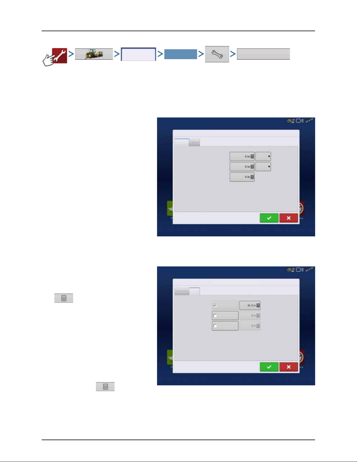
4 - System setup
Configuration
You r Spe cif ic
Configuration
Vehicle Offsets
Vehicle Offsets: JD 4630
Antenna
Hitch
Enter Distance from Vehicle References to the Antenna
Antenna Location
from Rear Axle
Antenna Location
from Centerline
Antenna Height from
Ground
In Front
Left
Vehicle Offsets: JD 4630
Antenna
Hitch
Enter Distance from Rear Axle to the Following Locations
Rear Drawbar
Rear Lift Arms
Front L ift Arm s
Vehicle Offsets
When the process of setting up a Vehicle is completed by using step-by-step procedure in “Installation” on page 31, you can
later re-configure vehicle offsets.
Vehicle offsets define where the machine’s rear axle and hitch is in relation to the GPS antenna. These settings are used for
accurate mapping and AutoSwath.
The GPS Offsets settings consist of two tabs: the Antenna Tab and the Hitch Tab.
Antenna Offsets tab
At the Antenna Tab, enter the distance from
locations on the vehicle to the antenna.
• Measure and enter the horizontal distance
from the rear axle to the position of the GPS
antenna.
Select IN FRONT or BEHIND to indicate the
position of the antenna in relation to the rear
axle.
• Measure and enter the horizontal distance
from the center line of the vehicle to the
position of the GPS antenna.
Select LEFT or RIGHT to indicate the position
from the vehicle center line.
• Measure and enter the vertical height of the
antenna above the ground.
NOTE! Accuracy when measuring for a specific setting is essential to ensure proper machine performance.
÷
Hitch Settings tab
The Hitch Tab allows you to enter in the distance
from four different mounting positions on the
tractor to the rear axle.
Press to enter these values in if using the
hitch point.
NOTE! Accuracy when measuring for a
÷
specific setting is essential to ensure proper
machine performance.
Mount Tab Settings
The Mount Tab will only be available when using a
Self-Propelled sprayer.
This allows you to enter in the application location
from the rear axle. Press to enter in the
distance and the drop-down box to select if it is in front or behind of the axle.
91
Page 94
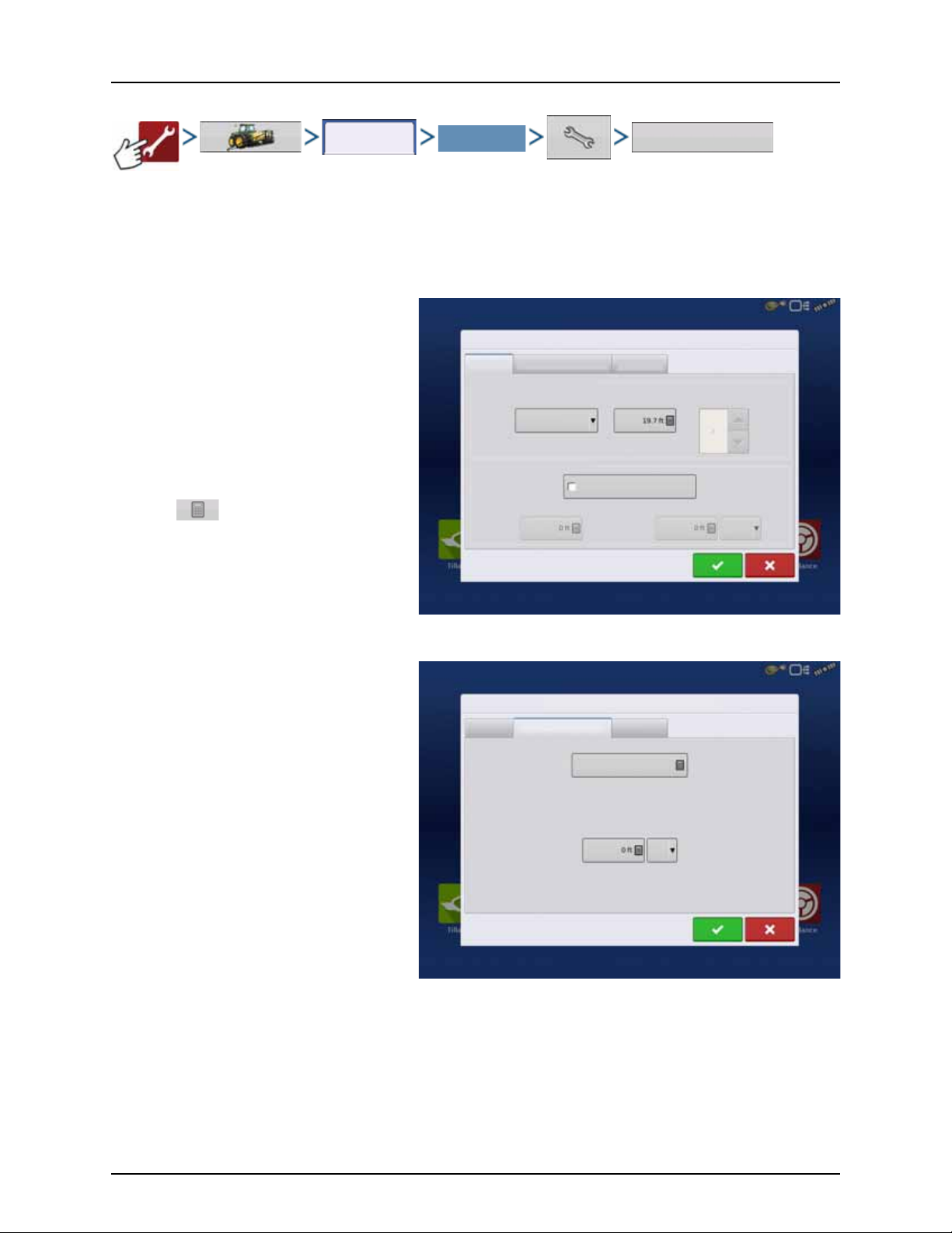
4 - System setup
Configuration
Select Your Specific
Configuration
Offsets
Implement Offsets: Hardi Commander
Implement Liquid with Hardi Sprayer
Implement Modeling
Implement Provides a Rear Hitch
Hitch to Axle
Distance
Lateral Offset from Centerline
Left
Implement Type
Standard
Front Hitch to Rear Hitch
Implement Rear Hitch
Heading
Aggressivene ss
Boom Height
Implement Offsets: Hardi Commander
Implement L iquid with Hardi Sprayer B oom Height
Forward/Backward Distance from Hitch
Left/Right Distance from Centerline
Left
Independent Section Offsets
Swath Section Offsets
The Implement Offsets screen opens. On a typical HARDI® configuration, this screen may consist of up to three tabs:
• Implement tab.
• Liquid with Hardi Sprayer tab.
• Boom Height tab.
Implement tab
Implement Modeling:
Implement Type:
• Standard
• Hardi SafeTrack
ATTENTION! For IntelliTrack sprayers, select
μ
the “Hardi SafeTrack” option.
Hitch to Axle Distance:
Press to type in value.
Type in the measured value from Hitch of the
sprayer to the axle.
Implement Rear Hitch:
No relevant settings for HARDI® sprayers.
Option should remain unchecked.
Liquid with Hardi tab
Forward/Backward Distance from Hitch:
• Set distance between the hitch eye and the
nozzles.
Left/Right Distance from center line:
• For asymmetric booms. As HARDI® booms
are never asymmetric, this option must be set
to 0 ft. Left or Right selection does not matter.
Boom Height tab
Forward/Backward Distance from Hitch:
• Set distance between the hitch eye and the
nozzles.
Left/Right Distance from center line:
• For asymmetric booms. As HARDI® booms
are never asymmetric, this option must be set to 0 ft. Left or Right selection does not matter.
92
Page 95
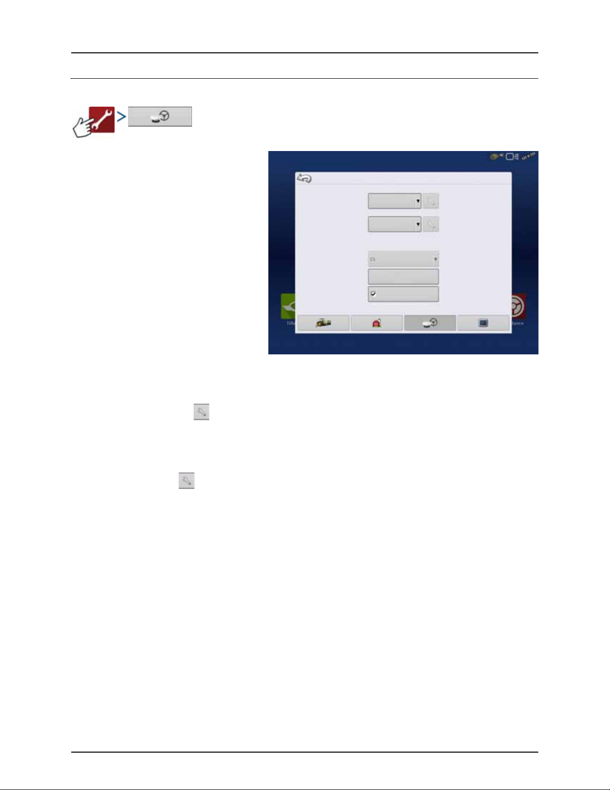
GPS Guidance/Steering Control
Require Differential
Correction for Guidance
GPS/Guidance Setup
Steering:
Manual Guidance
Lightbar
Settings
Operator Presence Alarm
(Autodetect)
Minutes
Setup
• Steering
• Manual Guidance
Select this to perform guidance by
lightbar while manually steering the
vehicle.
• ParaDyme/GeoSteer
Integrated steering system that can
be used with Self-Propelled sprayers
and as optional equipment for
tractors.
• OnTrac3
Assisted steering that is mounted on a
machine’s steering wheel.
• SteerCommand
Integrated steering system that can
be used with Self-Propelled sprayers
and as optional equipment for
tractors.
4 - System setup
ATTENTION! Pressing the next to the Steering options opens the guidance system settings for the selected
μ
guidance system.
• Receiver
Set type of GPS interface protocol to Autodetect, Serial, CAN or TSIP.
ATTENTION! Pressing next to the Receiver options opens the selected receiver’s specific settings. Populated
μ
settings vary from one receiver model to the next.
• Operator Presence Alarm
The Operator Presence Alarm disengages guidance control if the operator does not have any interaction with the
display for a specified period of time. Use the dropdown menu to specify the period of time before guidance is
automatically disengaged.
• Lightbar Settings
For more information, see “Lightbar Settings” on page 101.
• Required Differential Correction for Guidance
When unchecked allows guidance to operate without differential correction.
NOTE! In order to use guidance with the display, you must have a GPS receiver capable of a GPS output rate of 5 Hz
÷
or more.
93
Page 96

Receiver: GPS 6500
Serial
General
GPS Settings
Differential Source
Featu res
StableLoc
NMEA Talker
Age of Differential
Upgrade
Firmw are
General
Reset to
Defaults
Port A (Connected) Port B
None
4 - System setup
Serial GPS Settings
NOTE! Default settings for the 6000/6500 receivers should not need to be adjusted from factory settings.
÷
• Differential Source
Select choice of:
• GLIDE
• WAAS/EGNOS
• TerraStar®
• RTK External
• RTK.
Options available are based on receiver type
and unlocks.
• Wrench icon
Pressing the Differential Source Wrench
button opens different settings screens,
depending on the differential source
selected.
• Age of Differential
Displays the elapsed time since reception of last differential correction signal. The Age of Differential button is only
functional when GPS is connected.
• StableLoc checkbox
StableLoc maintains accurate steering – even when your correction signal is temporarily lost – by seamlessly
transitioning to the next available signal source. When the signal is restored, the system will then transition back to the
higher accuracy source, eliminating position jumps.
Press to enable.
• StableLoc Error Limit (RTK & TerraStar only)
When using StableLoc, select the error limit at which the system will no longer allow steering.
• Select + or – button to adjust the limit.
If your error limit is “4 in” and the system accuracy reaches that limit, steering will no longer be allowed until the error
decreases. If set to “none” accuracy of the differential source will not affect the ability to autosteer.
• Reset to Defaults
Press the Reset to Defaults button to restore receiver settings to the fac tor y de fault . Thi s will rem ove al l cu stom s ettin gs.
• NMEA Talker
This button disables the GLONASS prefix in the NMEA messages. If using the GPS receiver with legacy displays or a
device that does not support GLONASS messages, uncheck the box.
94
Page 97

WAAS/EGNOS Settings
Receiver: GPS 6500
Serial
General
Differential Source
WASS/EGNOS
WAAS/EGNOS Settings
PRN
Automatic
Receiver: GPS 6500
Serial
General
Differential Source
Ter ra Sta r
TerraStar Settings
Serial Number
Provider Settings
Freque ncy
Convergence
Threshold
Automatic Tuning
PRN
• Automatic
• WAAS
• EGNOS
• Custom
ATTENTION! Should be left on Automatic
μ
unless otherwise told by support.
4 - System setup
TerraStar Settings
• Serial Number
This box shows the serial number of your
receiver - used to purchase TerraStar
subscription.
• Automatic Tuning check box
Receiver will automatically select the
strongest frequency. Frequency drop-down
box will be grayed out when this is selected.
• Frequency
In the Frequency drop-down list box, select
the geographic region where you are
located. Only uncheck automatic tuning
when directed to by support (used to adjust
tuning).
• Convergence Threshold
The receiver uses the standard deviation of the solution to determine when the TerraStar position has converged. The
receiver will label the TerraStar solution as “converged” when the horizontal standard deviation reaches the
Convergence Threshold setting. Relaxing the convergence threshold shortens the time before a TerraStar solution is
reported as converged. However, it does not alter the absolute behavior of the solution.
NOTE! The use of TerraStar® differential requires purchase of a subscription from your HARDI® dealer. Settings related
÷
to using satellite differential correction vary based upon your geographic location. Setup details are explained on the
following pages. More specific information can be obtained through your HARDI® dealer. You will need to know the
serial number when contacting HARDI® to set up the receiver.
95
Page 98

4 - System setup
Receiver: GPS 6500
Serial
General
Differential Source
RTK External
Radio Settings
Radio Baud Rate
18400
Receiver: GPS 6500
Serial
General
Differential Source
RTK
RTK Settings
Server
Username
Passwor d
Streams
RTCM3_MAX - Connected
Disconnect
Info
Cellular / Activation
Activate
IP Address:
Modem Status: Connected
RTK External Settings
Setting the differential source to RTK External
enables GGA NMEA message output on Port B at
1 Hz.
Change the Radio Baud Rate to match the External
Radio connected to Port B.
RTK Settings - NTRIP
NTRIP
• Server
• Username
• Password
• Streams
• Disconnect/Connect - to the NTRIP Network
• Info - see “Info button” on page 97
Cellu lar
• IP Address - indicates a connection to the
Internet
• Modem Status
96
Page 99

NTRIP Server
Server
NTRIP Server
Server Address
Port
Cellular
IP Address:
Modem Status: Connected
Cellular Settings
Broadband
Username
Passwor d
Info
Stream Info
Stream:
Forma t:
Forma t Detail s:
Navigation System:
Network:
Authentication:
Iowa RTK Networ k
Required
• Server Address
• Port
Server Address and Port are provided by the NTRIP
Network.
4 - System setup
Cellular Settings
• APN
• Username
• Password
APN, Username and Password are Network
provided settings. Contact the Cellular provider
for this information.
Info button
• Stream
• Format
• Format Details
• Navigation System
• Network
• Authentication
The information shown on this screen is provided
by the NTRIP Network.
97
Page 100

4 - System setup
Receiver: GPS 6500
Serial
General
Differential Source
RTK
Radio Settings
Channel Spacing
Freque ncy
Set
Active
(Active)
Set
Active
Receiver: GPS 6500
Serial
General
Differential Source
RTK
Radio Settings
Channel
Set
Active
(Active)
Set
Active
RTK Settings - 400 MHz
• Channel Spacing
Use drop-down menu to select Channel
Spacing.
• Frequency
Press button to add a
Frequency.
Select frequency and press
button to delete selected
frequency.
Select frequency and press
button to make selected
frequency active.
RTK Settings - 900 MHz
Frequency
Press button to add a Channel.
Select channel and press button
to delete selected channel.
Select channel and press button
to make selected channel
active.
98
 Loading...