

Page 1

The Sprayer
Operator’s Manual
CONTROLLER
HC 8500/9500
Instruction book - SW 6.X
67023803 - Version 1.10
US - 06.2015
Page 2

Page 3

CONTROLLER
HC 8500/9500
Instruction book - SW 6.X
67023803 - Version 1.10
US - 06.2015
HARDI® reserves the right to make changes in design, material, or specification without notice thereof.
HARDI® and other product names are registered trademarks of HARDI® Inc. in the U.S. and in other countries.
Page 4

Page 5

Table of contents
1 - Welcome
Welcome letter ......................................................................................................................................1
2 - Safety Notes
Operator Safety .....................................................................................................................................1
Symbols ........................................................................................................................................................................................................................ 1
Precautions ................................................................................................................................................................................................................ 1
3 - Description
Display ...................................................................................................................................................1
General info ............................................................................................................................................................................................................... 1
System Uses ............................................................................................................................................................................................................... 1
System Features ...................................................................................................................................................................................................... 1
Display Hardware ................................................................................................................................................................................................... 2
USB Flash Drive ........................................................................................................................................................................................................ 3
Color Touch Screen .............................................................................................................................................................................................. 3
ISOBUS Technology .............................................................................................................................................................................................. 3
Screen Icon Conventions .................................................................................................................................................................................. 4
Map Screen ............................................................................................................................................5
Work Screen ..............................................................................................................................................................................................................5
Video ........................................................................................................................................................................................................................... 11
Miscellaneous ......................................................................................................................................12
About AutoTerrain/AutoHeight/AutoSlant ........................................................................................................................................ 12
Glossary of Application Settings ................................................................................................................................................................ 12
Fertilizer default Product Settings ............................................................................................................................................................ 13
4 - System setup
Installation ............................................................................................................................................1
Installation Instructions ...................................................................................................................................................................................... 1
Cable connections ................................................................................................................................................................................................2
Initial Startup ........................................................................................................................................6
General info ............................................................................................................................................................................................................... 6
Advanced Options ................................................................................................................................................................................................6
Location Specific Setup ...................................................................................................................................................................................... 7
Single Display ........................................................................................................................................................................................................... 8
Multiple Displays ................................................................................................................................................................................................. 10
Import Setup Data .............................................................................................................................................................................................. 14
Home Screen ......................................................................................................................................................................................................... 15
Quick Setup Guide ...............................................................................................................................16
General Info ............................................................................................................................................................................................................ 16
Configuration for Trailer and Lift sprayers ........................................................................................................................................... 16
Configuration for Self-Propelled sprayers ............................................................................................................................................ 33
Product setup ........................................................................................................................................................................................................ 46
Configuration ......................................................................................................................................49
Setup buttons ....................................................................................................................................................................................................... 49
Configuration button ....................................................................................................................................................................................... 49
Management button ........................................................................................................................................................................................ 51
User Setup button (Edit User) ..................................................................................................................................................................... 56
Permissions ............................................................................................................................................................................................................. 57
Permission Level for Operators .................................................................................................................................................................. 57
Accessing Setup Menus .................................................................................................................................................................................. 59
Accessing USB ....................................................................................................................................................................................................... 60
Forgotten Passwords ........................................................................................................................................................................................ 60
Display Button ....................................................................................................................................................................................................... 62
Virtual Terminal ..................................................................................................................................67
Virtual Terminal together with HC 8500/HC 9500 .......................................................................................................................... 67
General info about Virtual Terminal ........................................................................................................................................................ 67
TOC. 1
Page 6

Table of contents
Settings ................................................................................................................................................70
Speed Input Settings ........................................................................................................................................................................................ 70
Automatic Swath Control (AutoSectionControl) ............................................................................................................................ 71
Vehicle Offsets ....................................................................................................................................................................................................... 72
GPS Guidance/Steering Control ..........................................................................................................74
Setup ........................................................................................................................................................................................................................... 74
OmniSTAR Settings ............................................................................................................................................................................................ 76
OmniSTAR Settings — GPS 2500 .............................................................................................................................................................. 77
Serial Port Settings .............................................................................................................................................................................................. 78
Lightbar Settings .................................................................................................................................80
Setup ........................................................................................................................................................................................................................... 80
Guidance Tab on Mapping Toolbox ....................................................................................................................................................... 80
New Pattern - Straight ...................................................................................................................................................................................... 81
New Pattern - Adaptive Curve .................................................................................................................................................................... 82
New Pattern - Identical Curve ..................................................................................................................................................................... 83
New Pattern - Pivot ............................................................................................................................................................................................ 84
New Pattern - SmartPath ................................................................................................................................................................................ 86
AutoSave .................................................................................................................................................................................................................. 89
Manage Patterns ................................................................................................................................................................................................. 89
Pattern Groups ...................................................................................................................................................................................................... 90
Guidance Options ............................................................................................................................................................................................... 92
Liquid Rate Control ..............................................................................................................................97
Setup ........................................................................................................................................................................................................................... 97
Application Map Screen - Zoom to Detail ........................................................................................................................................... 99
Legend Select ........................................................................................................................................................................................................ 99
Rate Control: Product Control Toolbox ...............................................................................................................................................100
Loading Prescriptions .....................................................................................................................................................................................104
Shape File Conversion ...................................................................................................................................................................................105
External Drive ................................................................................................................................... 107
External Storage Operations ......................................................................................................................................................................107
5 - Operation
Map Screen ............................................................................................................................................1
Configuration Setup Screen ............................................................................................................................................................................ 1
Mapping Toolbox .................................................................................................................................................................................................. 1
Field Operations ....................................................................................................................................5
Operator Selection ................................................................................................................................................................................................ 5
Operator Log Out ................................................................................................................................................................................................... 5
Setup Event ................................................................................................................................................................................................................ 5
Field Finder ................................................................................................................................................................................................................9
Home Screen After Configuration ............................................................................................................................................................ 10
Work Screen Operations ................................................................................................................................................................................. 11
Rate Control Settings ........................................................................................................................................................................................ 11
Display Item Selection ..................................................................................................................................................................................... 12
Boom Height Control Options .................................................................................................................................................................... 13
Headlands ................................................................................................................................................................................................................ 14
Finalize Event ......................................................................................................................................................................................................... 21
Reports ................................................................................................................................................22
Summary Report .................................................................................................................................................................................................. 22
Smart Reports™ (HC 9500 only) .................................................................................................................................................................. 25
6 - Maintenance
General info ...........................................................................................................................................1
Service ........................................................................................................................................................................................................................... 1
Fuse Installation and Replacement ............................................................................................................................................................. 1
System and Upgrades ......................................................................................................................................................................................... 1
TOC. 2
Page 7

Table of contents
7 - Fault finding
Devices ..................................................................................................................................................1
Device Information ............................................................................................................................................................................................... 1
ISOBUS ...................................................................................................................................................3
ISOBUS VT ................................................................................................................................................................................................................... 3
VT Alarms and Trouble Codes ........................................................................................................................................................................ 4
ISOBUS Modules ....................................................................................................................................5
Modules not found ............................................................................................................................................................................................... 5
ISOBUS Configuration Mismatch .................................................................................................................................................................6
GPS ........................................................................................................................................................7
GPS Information ...................................................................................................................................................................................................... 7
GPS Button ................................................................................................................................................................................................................. 7
GPS Information - General Tab ...................................................................................................................................................................... 7
GPS Information - NTRIP ................................................................................................................................................................................. 11
8 - Technical specifications
Specifications ........................................................................................................................................1
Technical Specifications ..................................................................................................................................................................................... 1
Sprayer Offsets ......................................................................................................................................................................................................... 1
Appendix ...............................................................................................................................................2
Current File Formats ............................................................................................................................................................................................. 2
Legacy File Formats .............................................................................................................................................................................................. 2
9 - Warranty
Warranty policy and conditions ............................................................................................................1
TOC. 3
Page 8

Table of contents
TOC. 4
Page 9

1 - Welcome
1 - Welcome
Welcome letter
Dear Owner,
Thank you for purchasing a HARDI® product and welcome to the ever-increasing family of HARDI® sprayer owners.
Our sprayers and accessories are a familiar sight on North American farms. We believe that this results from growers
becoming increasingly conscious of crop protection input costs and the vital need for cost effective spray application
equipment.
Please take the time to thoroughly read the Operator’s Manual before using your equipment. You will find many helpful hints
as well as important safety and operation information.
Some of the features on your HARDI® controller were suggested by growers. There is no substitute for “on farm” experience
and we invite your comments and suggestions. If any portion of this instruction book remains unclear after reading it,
contact your HARDI® dealer or service personnel for further explanation before using the equipment.
For Product, Service or Warranty Information:
- Please contact your local HARDI® dealer.
To contac t H A RDI® d i r e c tl y :
- Please use the HARDI® Customer Service number: 1-866-770-7063
- Or send your email to CUSTSERV@hardi-us.com
HARDI® NORTH AMERICA INC. Visit us online at: www.hardi-us.com
1500 West 76th St.
Davenport, Iowa 52806
Phone: (563) 386-1730
Fax: (563) 386-1280
Sincerely,
Dale M. Szuminski
President
1.1
Page 10

1 - Welcome
1.2
Page 11

2 - Safety Notes
Operator Safety
Symbols
These symbols are used thorough the book to designate where the reader needs to pay extra attention.
This symbol means DANGER. Be very alert as your safety is involved!
€
This symbol means WARNING. Be alert as your safety can be involved!
±
This symbol means ATTENTION. This guides to better, easier and safer operation of your sprayer!
This symbol means NOTE.
÷
Precautions
Note the following recommended precautions and safe operating practices before using the sprayer.
General info
Read and understand this instruction book before using the equipment. It is equally important that other operators
€
of this equipment read and understand this book.
If any portion of this instruction book remains unclear after reading it, contact your HARDI® dealer for further
€
explanation before using the equipment.
Keep children away from the equipment.
€
Press the keys with the underside of your finger. Avoid using your fingernail.
€
Local law may demand that the operator is certified to use spray equipment. Adhere to the law.
€
Tractor driver’s seat is the intended working place during operation.
€
Service
Test with clean water prior to filling with chemicals. Rinse and wash equipment after use and before servicing.
€
Never service or repair the equipment while it is operating. Always replace all safety devices or shields immediately
€
after servicing.
Turn electrical power off before connecting and disconnecting the display and transducers, servicing or using a
€
battery charger.
If an arc welder is used on the equipment or anything connected to the equipment, disconnect power leads before
€
welding. Remove all flammable or explosive material from the area.
Do not use a high pressure cleaner to clean the electronic components.
€
2.1
Page 12

2 - Safety Notes
2.2
Page 13

3 - Description
Display
General info
The display is a full-featured, year-round hub of any precision farming operation. A full-color, high-brightness, highresolution touchscreen display is easy to read and offers powerful, year-round precision farming tools. Built-in manual
guidance, full-screen mapping, planter and application control, yield monitoring, real-time data logging and automated
steering make up the core functionality of the display.
ATTENTION! This manual only describes functions relevant for spray use with a HARDI® sprayer.
WARNING! Read manual completely before operating display. Understand and follow all operating and safety
±
instructions for proper use of this display. Failure to use display properly could result in an impairment of the safety
features of this product.
System Uses
• Manual Guidance
• AutoTerrain/AutoHeight/AutoSlant UC5
• ParaDyme™ automated steering
• Video Camera Inputs
• Mapping tillage operations
• Mapping and logging product application
• Mapping of all field boundaries, sub-boundaries, waterways and terraces
• Grain yield monitoring
• Variety logging
• Granular and liquid fertilizer application
• Liquid spray system control
• NH3 application control
• Application control of multiple bin spinner spreaders
System Features
• Sunlight-readable screen
• Rugged sealed enclosure
• Compatible with most NMEA GPS receivers
• HARDI® ISOBUS product control using industry standard CAN-bus interface
• Adjustable volume control
• Perspective 3D View Map
• Report preview
• Automatic field selection
• Automated module firmware upgrade
• Advanced GPS Diagnostics
• USB media slot
• 28-pin plug for JobCom connection.
• 28-pin auxiliary connection
• HARDI® mounting bracket
3.1
Page 14
3 - Description
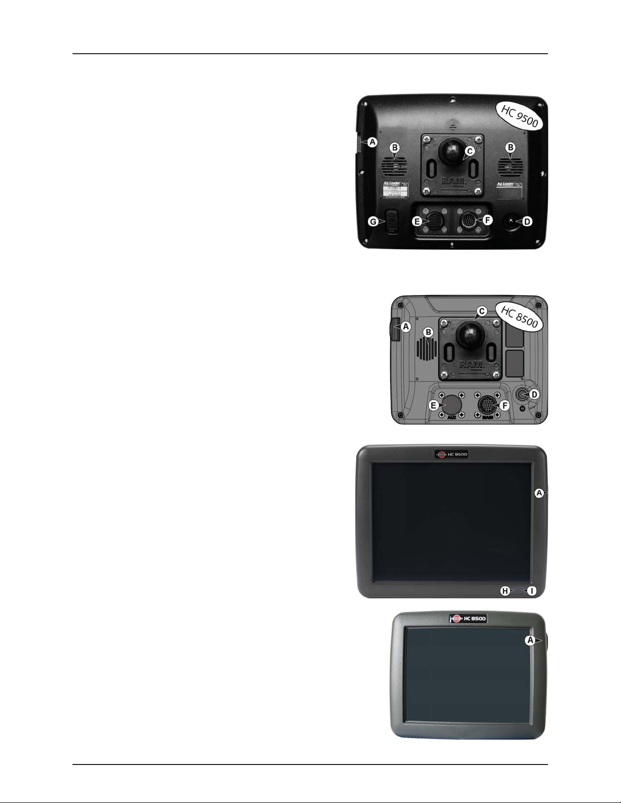
Display Hardware
Rear side
A. USB media slot
Used for data transfer in and out of the display.
B. Speaker
The built-in speaker is used for audible warnings. The volume can
be adjusted through the display setup routine.
C. RAM mount
D. Power/Reset switch
The Power/Reset switch is used for turning the display on and off
in installations where the system is connected to a continuous
power supply.
If the display ever stops responding, the manual power switch may
be held in for five seconds to restart the system. Only do this as a
last resort, data loss could occur during times of improper
shutdown.
E. 28-pin auxiliary connection
Used for camera input.
F. 28-pin plug
The 28-Pin round display connector contains CAN, RS-232 serial, and system
power and ground connections. It is compatible with some certain other
displays. Ethernet for ParaDyme automated steering is included in
connection.
VGA video output (not HC 8500)
G.
Can be used to connect to a video projector for demonstration purposes.
Front side
A. USB media slot
Used for data transfer in and out of the display.
H. Light sensitivity sensor (not HC 8500)
Used to automatically dim the display during nighttime or lowlight situations.
I. Power light (not HC 8500)
The power light displays one of three states:
Green = ON
Pulses amber = Standby Mode
Solid amber = Running on battery power
3.2
Page 15

3 - Description
USB Flash Drive
The display utilizes a USB Flash Drive slot that you can use to save and transfer your data in and out of the display.
Color Touch Screen
The display features a color touch screen display. The touch screen allows easy and intuitive navigation through the screens
on the display without the need for any external keypad or mouse devices. Here are a few key things to remember if you are
new to using a touch screen device:
• Do not use any sharp objects for running the touch screen device, this could result in damage to the display. Using the
tip of a finger is the recommended method of operating the display touch screen.
• Do not use any harsh chemicals to clean the touch screen. Using a damp soft cloth or an anti-static wipe made
specifically for cleaning computer displays is the correct way to clean the screen and the enclosure.
• The touch screen requires only a gentle touch of about half-second in duration to operate correctly. A common
mistake is to try to navigate too quickly through the system using firm taps instead of gentle presses.
ISOBUS Technology
The ISOBUS system uses Controller Area Network (CAN) technology. CAN systems are comprised of individual modules, each
with their own high speed processor, connected through a high-speed communications cable.
CAN has many benefits:
• Greater ability to configure and expand the system.
• Compatibility.
• Simpler installations with less wiring.
• Increased system dependability.
3.3
Page 16
3 - Description
Start Date
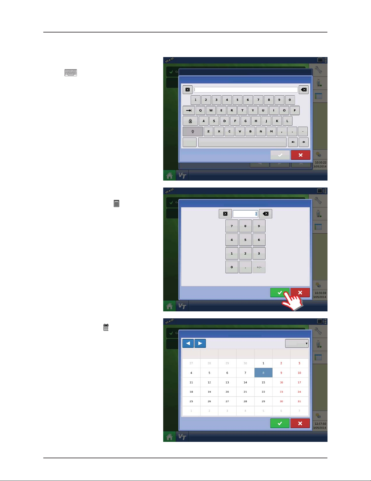
Screen Icon Conventions
The following control buttons are made available for entering names and calibration values into the system.
An on-screen Keyboard is made available when
appropriate for use during all setup processes.
Press the button to access the on-screen text
entry screen.
Symbols
An on-screen Numeric Keypad is made available
for changing configuration settings and
calibration numbers. Press the button to access
the on-screen numeric entry screen.
An on-screen calendar is made available for
changing dates. Press the button to access the
calendar screen.
3.4
Start Date
March 2015
Monday Tuesday Friday
Wednesday Thursday
Monday
Saturday Sunday
Page 17
3 - Description
Map Screen
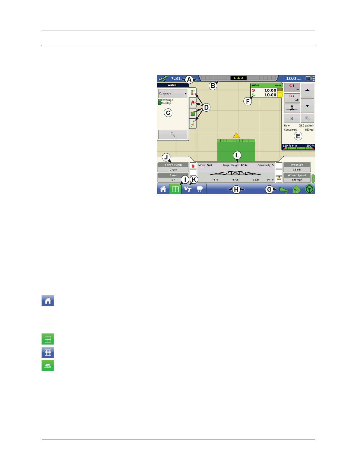
Work Screen
The appearance of the Map screen varies, depending upon which operation you are performing, and your specific operating
configuration.
A. Status Bar
B. On-screen Light bar
C. Mapping Toolbox
D. Mapping Function Tabs
E. Product Control Toolbox
F. Product Tabs
G. Function Buttons
H. Task Bar
I. Main Screen Buttons
J. Equipment Tab
Virtual Terminal Button
K.
L. AutoTerrain/AutoHeight/AutoSlant Settings
The task bar (H) displays buttons relating to various functions of the display. These buttons and status indicators include:
• Home
• Mapping
• AutoSectionControl (Autoswath)
• Logging
These buttons are shown in front of a green background when you are at that screen; otherwise they are shown in front of
a blue background.
Equipment Tabs
Different Display Items can be selected by pressing the Equipment tabs (J).
Home Button
Pressing the Home button takes you to the Home screen.
Map Button
Pressing the Map button takes you to the Map screen. Pressing it more than once cycles the Map screen to zoom in and out.
ZOOM DETAILS
ZOOM TO EXTENT
PERSPECTIVE VIEW
NOTE! The Perspective View is only available when guidance is active.
÷
3.5
Page 18

3 - Description
Video Button
Pressing this button takes you to the video screen. Pressing this button repeatedly cycles through the video inputs.
NOTE! For more information on the Video screen, see “Video” on page 3.11.
÷
AutoSwath Button
Pressing this button turns the AutoSwath feature on and off.
AutoSwath - ON
AutoSwath - OFF
AutoTerrain/AutoHeight/AutoSlant button
The AutoTerrain/AutoHeight/AutoSlant Engage button enables boom height control.
AutoTerrain/AutoHeight/AutoSlant Engage - Enabled (Automatic Mode)
• When enabled the display beeps three times.
AutoTerrain/AutoHeight/AutoSlant Engage - Disabled (Manual Mode)
• When you disable Automatic Mode on any part of the boom and the display switches to Manual Mode, this
button turns grey and the display beeps twice.
• If less than the full boom remains in Manual Mode, the display will continue beeping twice every three seconds.
AutoSteer Button
The Engage icon status of the AutoSteer system. The appearance of this icon displays the following:
AutoSteer is ON and ready to use.
AutoSteer is OFF but ready to engage.
AutoSteer is OFF and unable to engage.
NOTE! For more information, see “General info” on page 6.1.
÷
Master Switch Status
This bar shows that the Master Switch is active.
Master Switch - ON (GREEN) Master Switch - OFF (RED)
3.6
Page 19
3 - Description
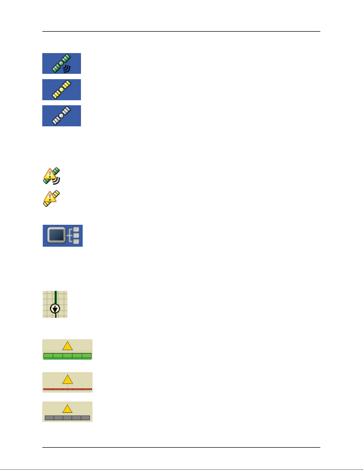
GPS Signal Indicator
The GPS button in the upper left-hand corner of the Map screen, displays the following colors:
Differential GPS
Green if you are receiving a differential GPS signal
GPS - No differential
Ye l l ow if you are receiving GPS, but no differential signal
No GPS
Grey if you are receiving no GPS signal.
Flex Mode icon
Appears for ParaDymes using Flex Mode. Flex mode provides continuity of position solution to maintain automated steering
by seamless flexing (transitioning) to a lower accuracy mode when a higher accuracy mode is lost; such as loss of the RTK
radio link.
Flex Mode - ON (GREEN)
Flex Mode - Exceeded (YELLOW)
Device Information button
Opens screens that display Device Information, Memory, Display, and display diagnostics.
NOTE! For more information, See “Device Information” on page 7.1.
÷
Vehicle Icons
Vehicle Icon - Zoom to Extent
The Vehicle Icon is shown by an arrow inside a circle if the Map screen is viewed in Zoom to Extent.
The vehicle appears as a gold-colored triangle if the Map screen is viewed in Zoom Detail. The appearance of the zoomedin icon changes depending upon the data being logged in the field.
Vehicle Icon - Spraying (with all sections ON)
When the vehicle is logging data from the implement split into sections, then these sections appear
in the implement icon.
Vehicle Icon - Not Spraying. Sections OFF by Switch (with all sections OFF)
The vehicle is not logging data, when the implement icon appears as a red bar.
Vehicle Icon - Not Spraying. Sections OFF by AutoSectionControl (AutoSwath) (with all sections OFF)
The vehicle is not logging data, when the implement icon appears as a grey bar.
3.7
Page 20
3 - Description
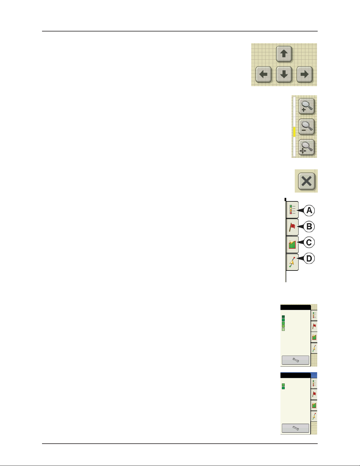
Map Screen
Press the grid area of the Map screen, and four arrow icons appear at the bottom right of the
Map screen. Pressing these arrow icons will move the center of the Map screen in the
direction of the arrow button.
The Zoom Tool icons, which resemble a magnifying glass, are shown at the right-hand side of the Map screen.
• Pressing the zoom tool with the plus sign increases the scale of the Map screen.
• Pressing the zoom tool with the minus sign decreases the scale of the Map screen.
• Pressing the zoom tool with the four arrows underneath re-centers the Map screen and brings its scale
back to the default.
The escape button, visible when in full screen mode.
• Pressing the button will escape from full screen mode.
Mapping Toolbox
At the upper left hand side of the Map screen is the Mapping Toolbox. Press any of the four buttons on the
toolbox and it expands. The toolbox consists of the following buttons:
A. Map Legend
B. Map Markers
C. Boundary
D. Guidance
The Map Legend, Map Markers and Boundary buttons are explained in the rest of this chapter. The
Guidance button is described in “General info” on page 6.1.
Map Legend tab
Press the Map Legend button at the top of the Mapping Toolbox, and the Legend appears, either for Rate or Coverage.
Map Legend - Rate
Map Legend - Coverage
Water
Soybeans
Coverage
Coverage
Overlap
RATE
3.8
Page 21
3 - Description
Map Options
Markers
Rock
Washout
Weeds
Hole
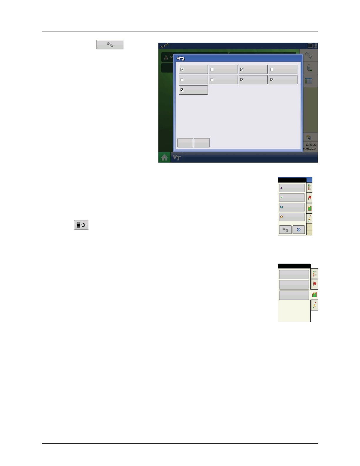
Map Options
Press the Legend Setup tool, and the
Legend Select screen appears. Here you can adjust
Legend Settings, clear the map.
• Clear Map
Permanently removes on-screen map from
Data Guidance Boundary
Reference Rx Tile Grid
the active field operation, but the log data
will still be exported to the USB drive.
WARNING! Once you clear the map, this
±
information cannot be retrieved.
Top og ra ph y
• Load Reference
Loads a list of maps of previous operations
performed in that field. For each operation,
Clear Map
Load
Reference
you can view As-Applied or Coverage
attributes; and Varieties if you are performing
a Planting operation.
Markers tab
Markers are a collection of point objects that are available on the Map Markers tab of the Mapping
Toolbox. Map markers allow you to map points on the go in order to identify specific features within a
field. Press an individual marker to indicate a Map Marker on the Map screen.
If all of the Markers that you created are not immediately visible in this screen, use the Cycle Markers
button to view more that you created.
Map Options
Marker
Cycle Markers
Field tab
Field tab allows the user to setup boundaries, headlands, and topography.
Field
Boundary
Headlands
Topo gr aph y
3.9
Page 22
3 - Description
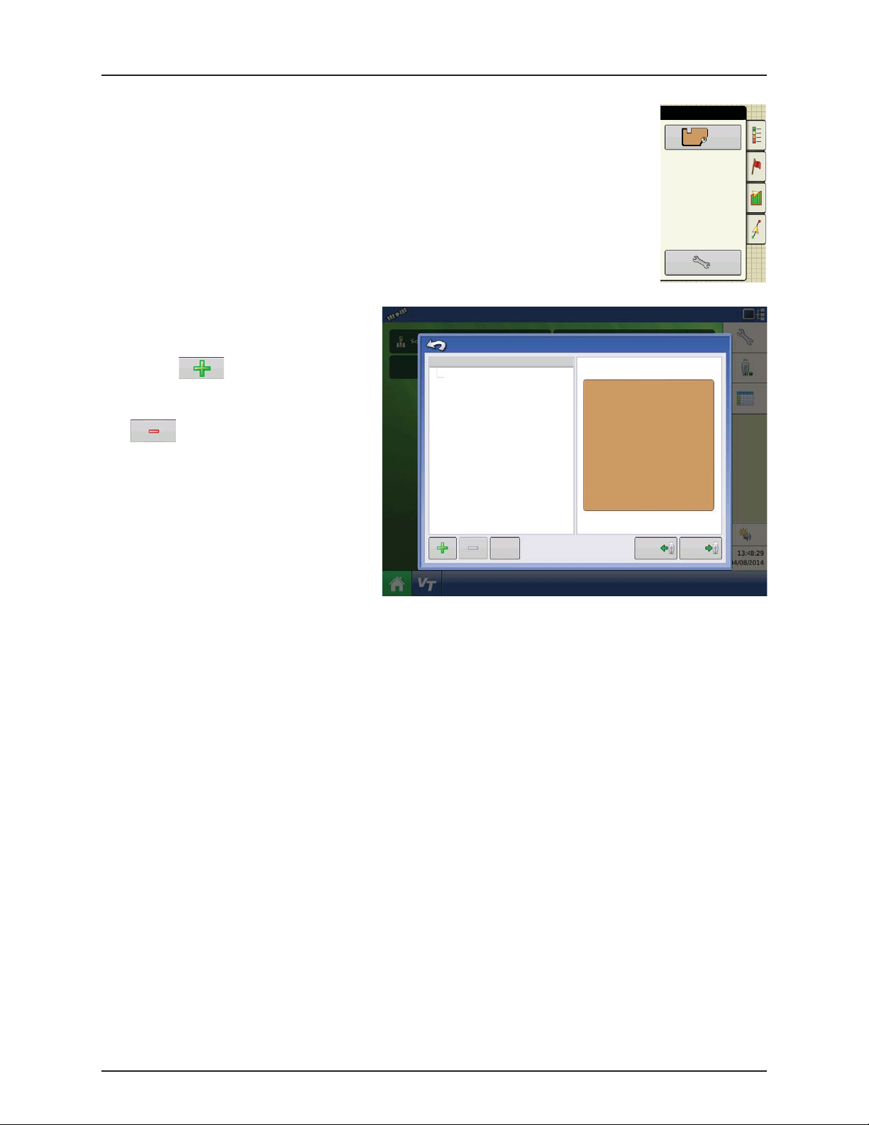
Boundary Options
Boundary tab
Press the Boundary button on the Field tab to access the Boundary Options screen.
On the Boundary Options screen, you can Import
Boundaries, Export Boundaries, and Clear All
Boundaries.
• Pressing on the Boundary Options
screen opens the Boundary Settings screen.
• Highlighting an existing region and pressing
on deletes that region.
• Use Import and Export buttons to move
regions to and from USB drive.
• Press Clear All to permanently delete all
Boundary information for that field.
WARNING! Once you clear this information,
±
it cannot be retrieved.
Outer (98.2 ac)
Boundary Options
Region
Clear All
Boundary
Start
98.2 ac
Import Export
3.10
Page 23
3 - Description
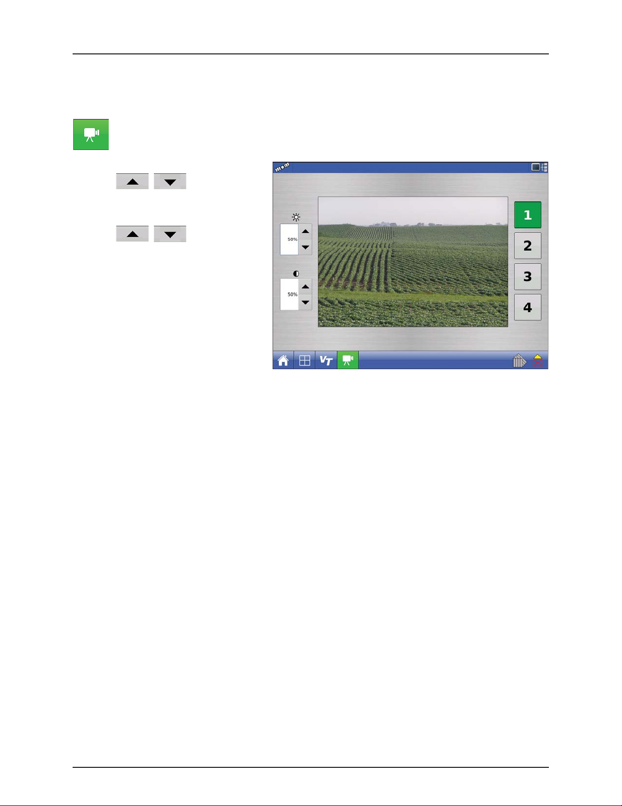
Video
NOTE! Video is only available when enabled in the Console Setup menu - see “Display Button” on page 4.62.
÷
Video button. Press and the Video screen appears.
• Brightness
Press / to increase or
decrease the brightness of the video input.
• Contrast
Press / to increase or
decrease the contrast of the video input.
• Camera Number Selection
The display can receive input from up to four
video cameras. Press the numbered buttons
to switch views between video cameras.
NOTE! You can adjust the brightness and
÷
contrast of each input individually.
3.11
Page 24

3 - Description
Miscellaneous
About AutoTerrain/AutoHeight/AutoSlant
For the use of AutoTerrain/AutoHeight/AutoSlant together with HC 8500/9500, please refer to the specific
AutoTerrain/AutoHeight/AutoSlant UC5 instruction books.
Glossary of Application Settings
Configuration Settings
• Rate Outside of Field
Rate that will be used outside of the field boundary. This is controlled by the HARDI® VT software.
• Rate Display Smoothing
Determines how the feedback from the JobCom will be displayed on the Work Screen.
• When checked, the system will display the target rate when the application rate is within 10% of the target rate
setting.
• When unchecked the system will display the raw feedback from the rate sensor.
• Controller Time Delay
Compensates for any delay in the control system. This is controlled by the Look-Ahead settings - see “Automatic Swath
Control (AutoSectionControl)” on page 4.71.
Speed Input Settings
• Primary Speed Source
Main source used by the display.
• Backup Speed Source
If the primary speed source fails, the display will use the backup speed source if one is available.
• Manual Speed
If both of the sources are unavailable, manual speed can be used in order for the control channel to provide
application. Manual speed setting is for use during static machine testing or by the control system in the absence of
primary and backup speed signals.
Automatic Swath Control Settings
• Turn-On Look-Ahead
Determines how far ahead the system looks to turn the swath sections back on. This setting compensates for any delay
in the product control system when the sections are turned on.
• Turn-Off Look-Ahead
Determines how far ahead the system looks to turn the swath sections off. This setting compensates for delay in the
product control system when the boom sections are turned off.
• Outside Boundary Option
Determines the behavior of the sections when exiting the field boundary or prescription-mapped area.
• Coverage Option
Based on the coverage option selected, this setting determines the behavior of the swath section when
entering/exiting an already applied area or field boundary. Options available include: Minimize Skip, Minimize Overlap,
and User Defined Percentage.
Field Notes
• Auto Generate Report
When checked, this option will automatically generate the SmartReport each time product application is completed
and the Field button is selected.
• Prompt for Report Details
When checked, this option will automatically launch the region summary data collection dialog each time a new
region is created at the run screen during application rate control.
3.12
Page 25

3 - Description
• Report Map Appearance
Multi-Color Rate
• Select this option to have the SmartReport display the application maps using the rate legend as displayed on
the run screen.
Single Color Coverage
• Select this option to have the SmartReport display single color product coverage maps.
Run Screen
• AutoSwath (AutoSectionControl)
Use to enable/disable automatic control of boom section on/off state based upon field boundaries, prescription files,
and previously applied areas.
Fertilizer default Product Settings
Material Ty pe Abbreviated
Anhydrous Ammonia Liquid under
28% UAN Liquid 28% UAN
30% UAN Liquid 30% UAN
32% UAN Liquid 32% UAN
Ammonium
polyphosphate (starter)
pressure
Liquid Ammonium
name for
display and
predefined
name for SMS
NH
3
polyphosphate
Percentage (in terms of lbs.100 lbs.) Density
N P (P2O5) K (K2O)
82 0 0 5.14 lbs./gal. (at
60°F)
28 0 0 10.67
30 0 0 10.86 lbs./gal.
32 0 0 11.06 lbs./gal.
10 34 0 11.73 lbs./gal.
3.13
Page 26

3 - Description
3.14
Page 27

4 - System setup
Installation
Installation Instructions
All machine installation and mounting kits are shipped with instructions specific to that kit. Instructions include special
details relating to mounting, wiring and display configuration.
Mount the display to a secure support inside the vehicle cab. When choosing a mounting location, consider if the display:
• is readily accessible to the machine operator.
• does not obstruct the machine operator's normal driving view.
• does not interfere with or limit access to any of the existing machine controls.
• is fitted so the ISOBUS system cabling is routed and secured without interfering with existing machine controls.
WARNING! If drilling holes is required during the mounting process, care must be taken to ensure that damage is not
±
done to existing vehicle wiring, mechanical, or cab structure. Refer to vehicle manufacturer documentation for
specific details on your equipment. Follow all OEM instructions, cautions, and warnings when working around
equipment.
Components of Ram mount kit (HARDI® Part # 72802400):
A. RAM Base
B. RAM Arm
C. Base
4.1
Page 28
E2
E1
E3
E4
E5
E
H
B4
B3
H1
F
B2
D
B
B1
C
A
B
C
A
B
A
C2
*
A
B
C
A1
A2
A3
A4
A5
A8
A7
A9
A6
A10
C1
G
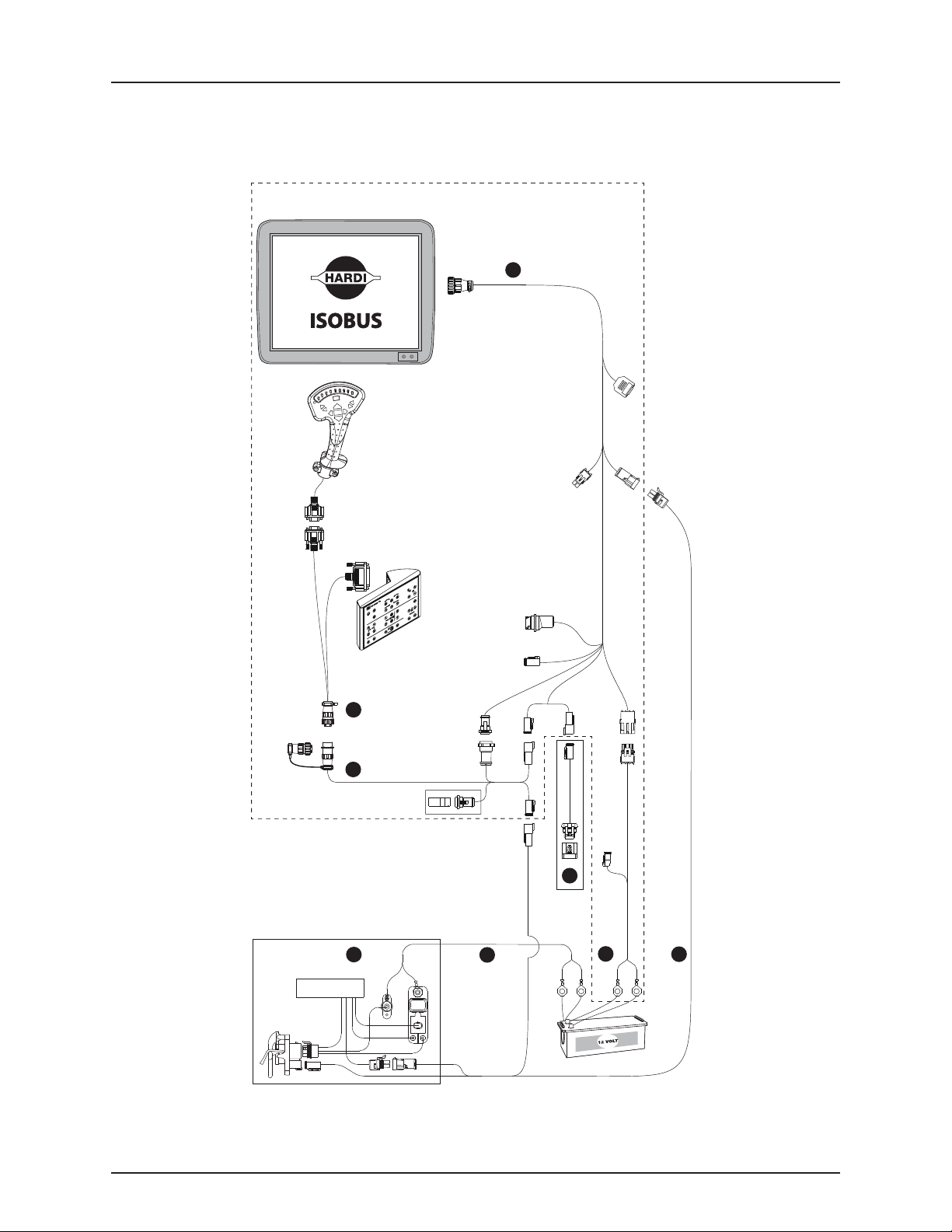
4 - System setup
Cable connections
Non ISOBUS Tractor
4.2
Page 29
I
J
J3
J4
J2
J1
K
C
A
B
C
A
B
A
C2
*
A
B
C
A1
A2
A3
A4
A5
A8
A7
A9
A6
A10
C1
G
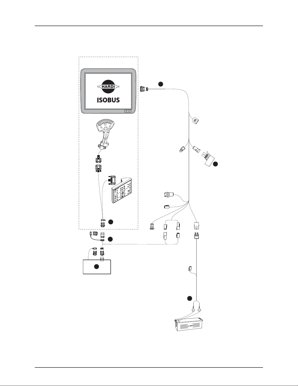
4 - System setup
ISOBUS Tractor with cabin connector (alternative 1)
Alternative 1: Display, SetBox and Grip connected to cabin connector.
4.3
Page 30
I
K
L
C
A
B
C
A
B
A
C2
*
A
B
C
A1
A2
A3
A4
A5
A8
A7
A9
A6
A10
C1
G
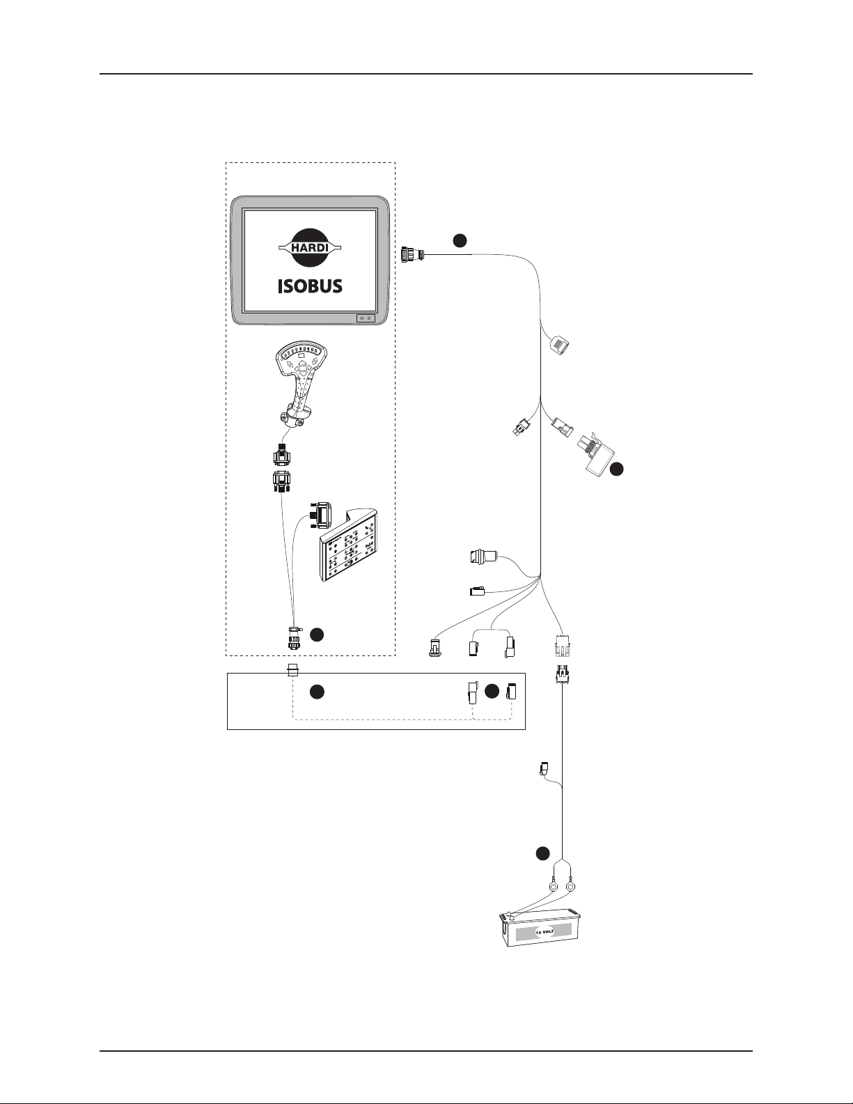
4 - System setup
ISOBUS Tractor with cabin connector (alternative 2)
Alternative 2: Display connected to tractor ISOBUS. SetBox and Grip connected to cabin connector.
4.4
Page 31
I
E2
E1
E3
E4
E5
E
L
C
A
B
C
A
B
A
C2
*
A
B
C
A1
A2
A3
A4
A5
A8
A7
A9
A6
A10
C1
G
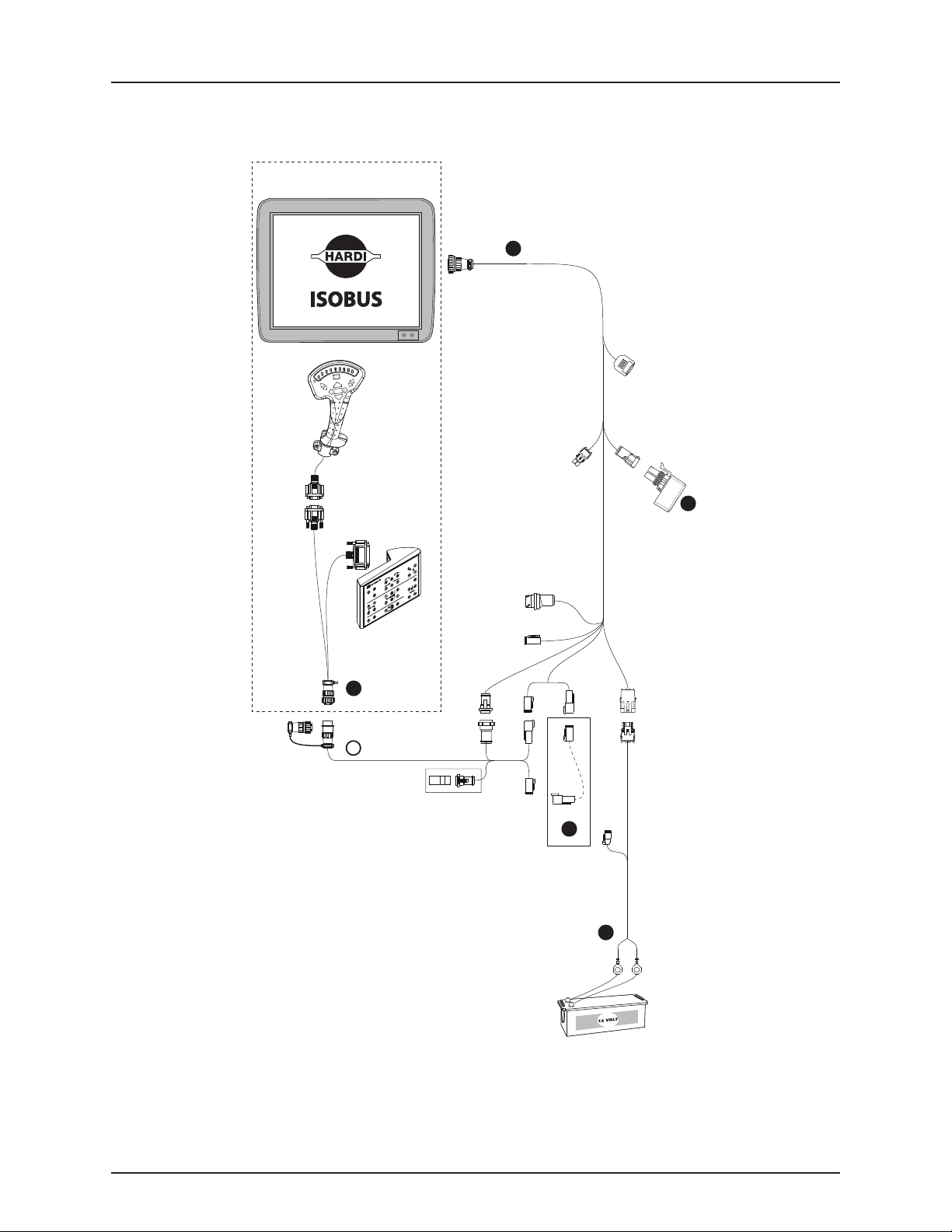
4 - System setup
ISOBUS Tractor without cabin connector
4.5
Page 32
4 - System setup
Advanced Options
Initial Startup
General info
An Initial Setup wizard is presented on startup. The wizard is presented if the display is brand new out-of-the-box with 6.0
software or following the 6.x upgrade.
NOTE! Not all of the following parts may be required to follow - it depends on your specific setup.
÷
Once the wizard is completed, it is not shown again unless the display memory is cleared.
Advanced Options
Press “Advanced” button on Language Selection
screen (first screen to appear on initial startup).
Display Setup: Select Language
Language
English/US
Select:
• Restore Backup
• Upgrade Firmware
• Unlock Display Features
NOTE! Using the Restore backup option is
÷
not the proper method to get multiple
displays set up to be the same. Use the
AGSETUP file.
It is acceptable to complete the initial setup wizard
and then upgrade. Setup information will not
change.
• On a “clean” display going out for service, to
stand in for a failed display, the customer
should use the Restore backup option in the
initial setup wizard.
Restore
Upgrade
Featu re
Unlocks
Advanced
Advanced Options
Restore data from a backup file (same display model only)
Upgrade the display firmware.
Unlock display features.
4.6
Page 33

Location Specific Setup
1. Language
A. Select your language.
B. Press to confirm.
2. Unit System
A. Press to select units.
B. Press to confirm.
4 - System setup
Display Setup: Select Language
Language
English/US
Advanced
Display Setup: Select Units System
3. Set Time and Date:
A. Press to select Time Zone
B. Press to set Time and Date
C. Press to confirm.
Unit system
Imperial
Display Setup: Set Date & Time
Time Zone
Americas (Central Time)
4.7
Page 34
4 - System setup
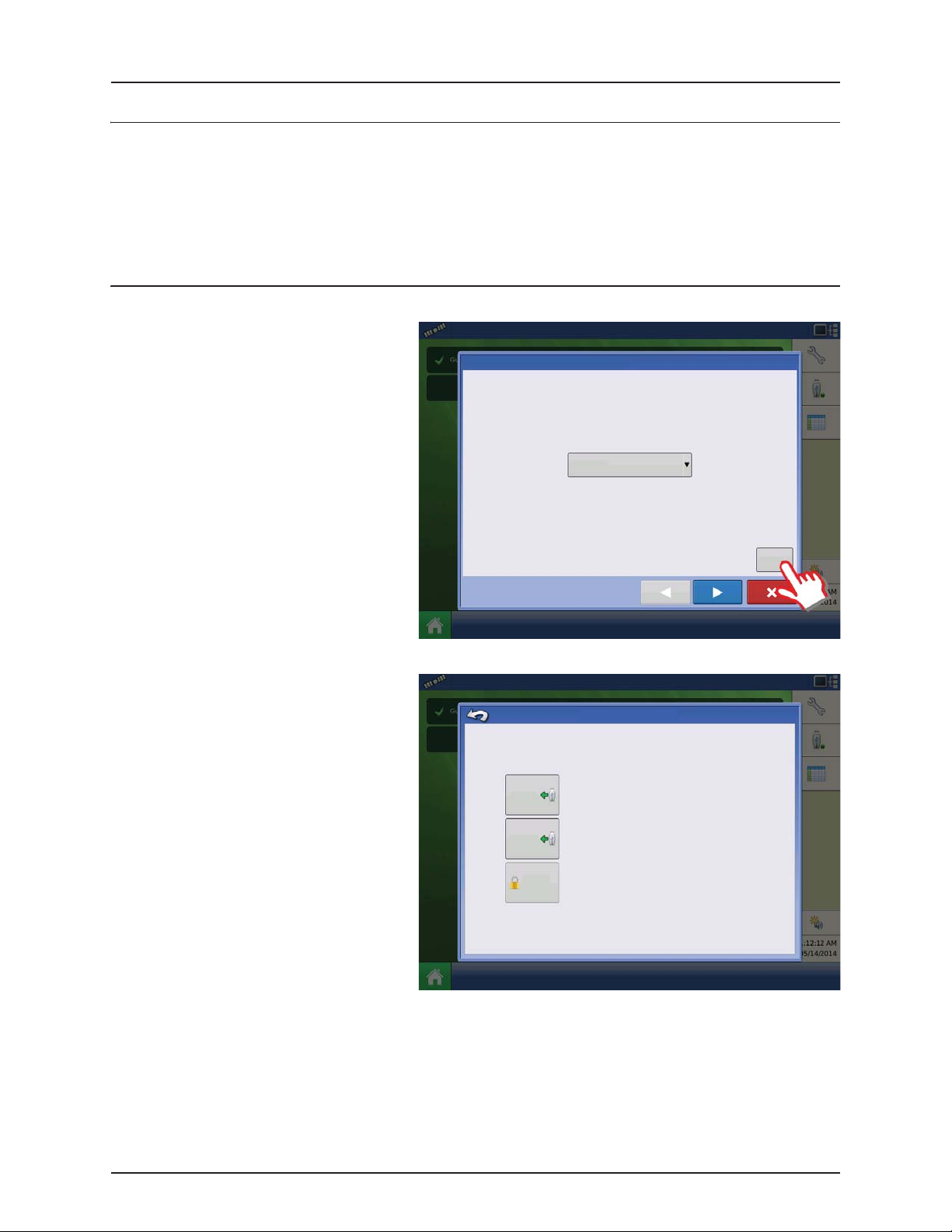
4. Set Time and Date.
Press to confirm.
Time and Date
Hours Minutes AM/PM Format
Single Display
Used if you have only one display to setup.
A. Press “Single Display” button.
B. Press to continue.
AM
MonthDay Year
Display Setup: Select Single or Multiple
Single Display
12 Hour
Set to
GPS Time
and Date
Multiple Displ ay
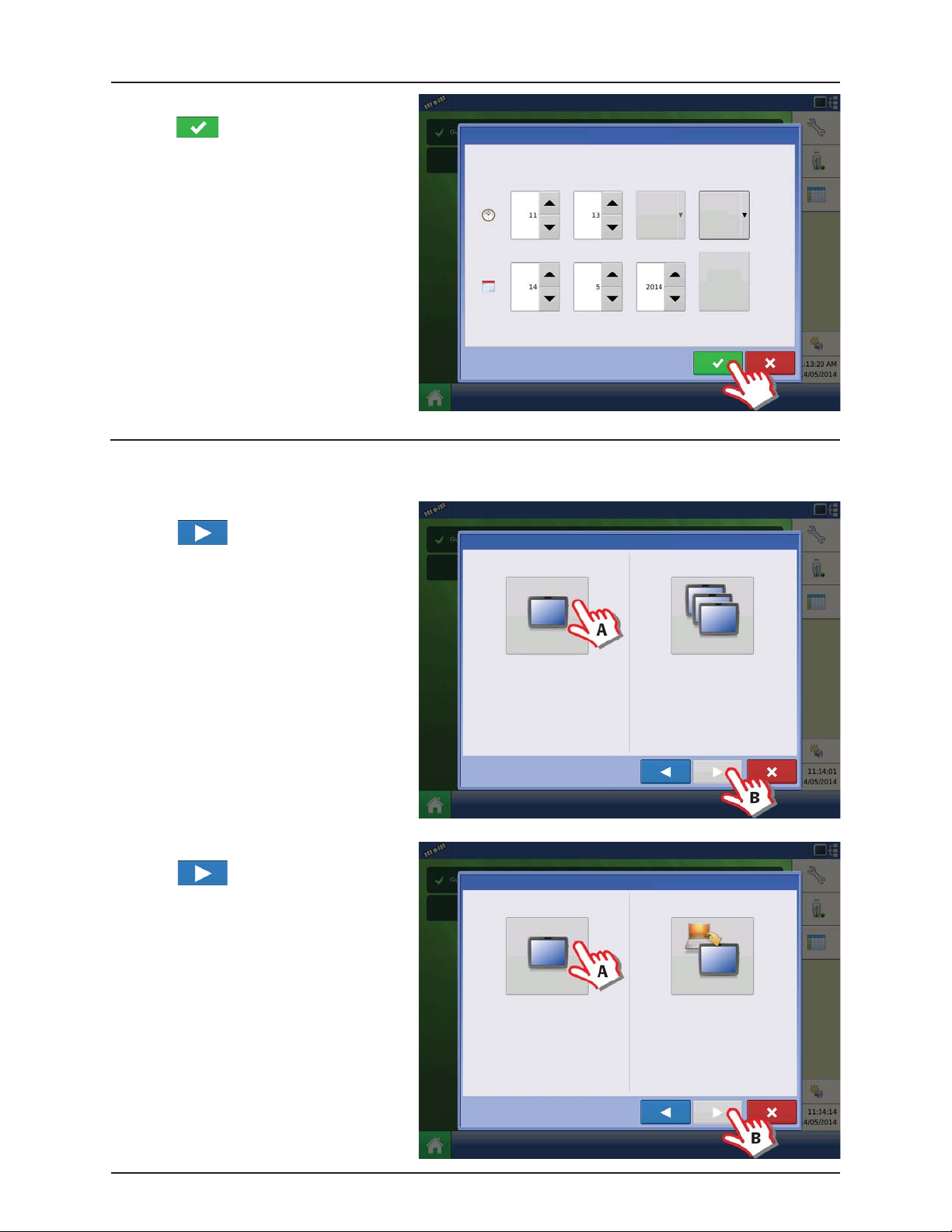
New setup
A. Press “New Setup” button.
B. Press to continue.
Select “Single Display” if you only have one
Integra, Versa, Compass, or HC9500/HC8500 in
your operation.
Display Setup: Select New or Import
New Setup
Select “New Setup” to perform all setup
through the display user-interface.
Select “Multiple Displays” to share setup
items between Integra, Versa, Compass, and
HC9500/HC8500 displays.
Import Setup
Select “Import Setup” to select an AgSetup
file to import setup items from your
computer.
4.8
Page 35

A. Press to enter a Display Owner
(Business Name).
B. Press to enter a display nickname.
C. Press to continue.
Import setup
A. Press “Import Setup” button.
B. Press to continue.
4 - System setup
Display Setup: Set Owner
Display Owner (Business Name )
Display Nickname
Display Setup: Select New or Import
A. Select desired setup file from directory.
B. Press to accept the setup and return
to Home screen.
New Setup
Select “New Setup” to perform all setup
through the display user-interface.
Display Setup: Select Ag Setup File
Name Size Date Modified
Select “Import Setup” to select an AgSetup
file to import setup items from your
computer.
Import Setup
4.9
Page 36

4 - System setup
Press to accept and import setup file.
A. Press to select a Display Owner
(Business Name).
B. Press to enter a display nickname.
Display Setup: Review Import
Management
Grower/Farm/Field
Allegon County
New Modified Conflicting Resolved
Display Setup: Set Owner
C. Press to accept the setup and
return to Home screen.
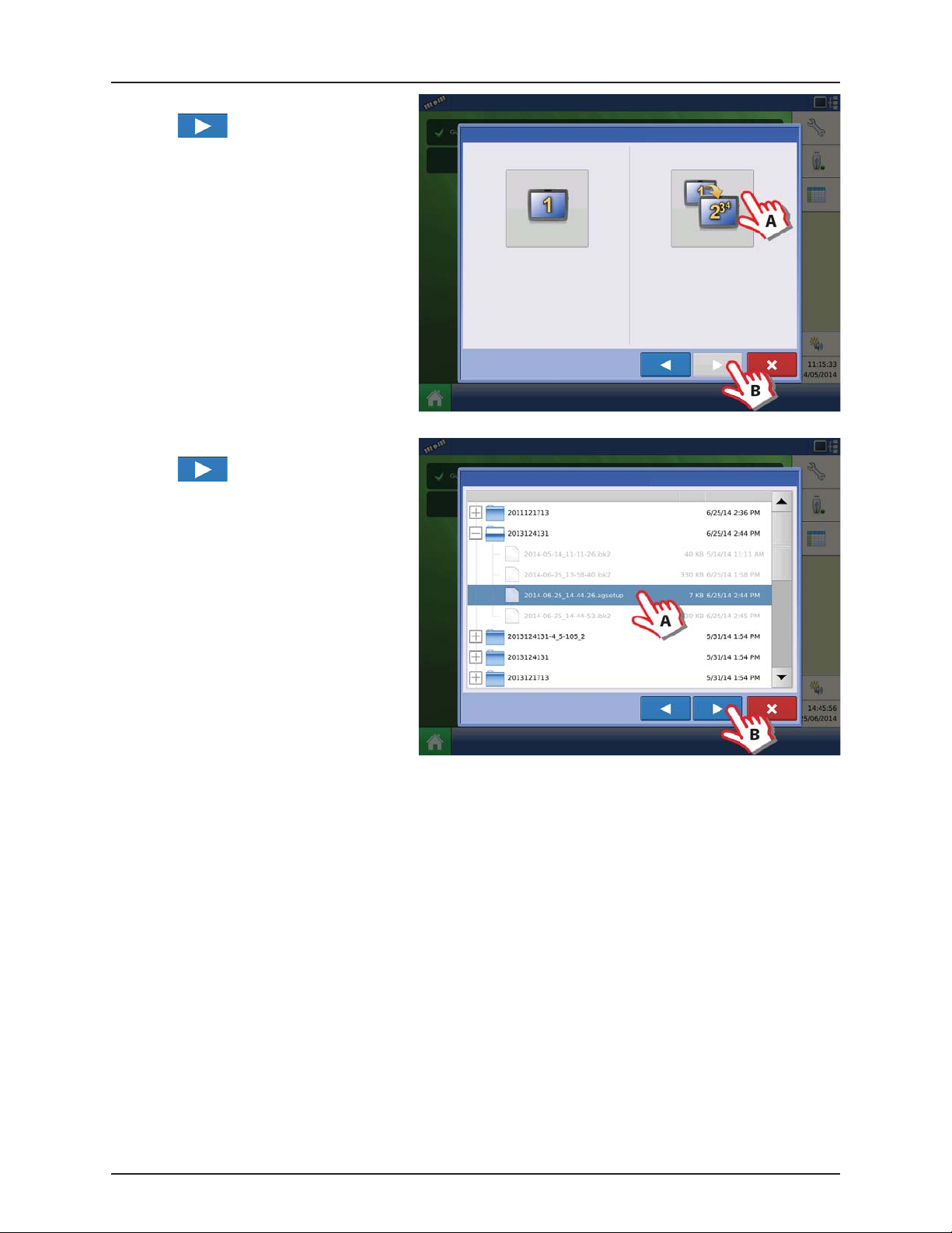
Multiple Displays
Setup First Display
A. Press “Multiple Display” button.
B. Press to continue.
Display Owner (Business Name )
Display Nickname
Display Setup: Select Single or Multiple
4.10
Single Display
Select “Single Display” if you only have one
Integra, Versa, Compass, or HC9500/HC8500 in
your operation.
Multiple Displ ay
Select “Multiple Displays” to share setup
items between Integra, Versa, Compass, and
HC9500/HC8500 displays.
Page 37

A. Press “First Display” button.
B. Press to continue.
4 - System setup
Display Setup: Select First or Other
New setup
A. Press “New Setup” button.
B. Press to continue.
First Dis play
Select “First Display” to export an AgSetup file
from this display to import into additional
displays (with version 3.0 or higher).
Display Setup: Select New or Import
New Setup
Select “New Setup” to perform all setup
through the display user-interface.
Additional Display
Select “Additional Display” to import setup
items from an AgSetup file from an existing
display.
Import Setup
Select “Import Setup” to select an AgSetup
file to import setup items from your
computer.
A. Press to enter a Display Owner
(Business Name).
B. Press to enter a display nickname.
C. Press to accept the setup and return
to Home screen.
Display Setup: Set Owner
Display Owner (Business Name )
Display Nickname
4.11
Page 38

4 - System setup
Import setup
A. Press “Import Setup” button.
B. Press to continue.
Display Setup: Select New or Import
A. Select desired setup file from directory.
B. Press to accept the setup and return
to Home screen.
New Setup
Select “New Setup” to perform all setup
through the display user-interface.
Select “Import Setup” to select an AgSetup
file to import setup items from your
computer.
Import Setup
Import Setup: Select AgSetup File
Name Size Date Modified
Setup Additional Display
A. Press “Multiple Display” button.
B. Press to continue.
4.12
Display Setup: Select Single or Multiple
Single Display
Select “Single Display” if you only have one
Integra, Versa, Compass, or HC9500/HC8500 in
your operation.
Select “Multiple Displays” to share setup
items between Integra, Versa, Compass, and
HC9500/HC8500 displays.
Multiple Displ ay
Page 39
A. Press “Additional Display” button.
B. Press to continue.
4 - System setup
Display Setup: Select First or Other
A. Select desired setup file from directory.
B. Press to continue.
The business created on the first display,
and any other management and
equipment items, will be imported to the
additional displays.
First Dis play
Select “First Display” to export an AgSetup file
from this display to import into additional
displays (with version 3.0 or higher).
Import Setup: Select AgSetup File
Name Size Date Modified
Additional Display
Select “Additional Display” to import setup
items from an AgSetup file from an existing
display.
4.13
Page 40
4 - System setup
Resolve
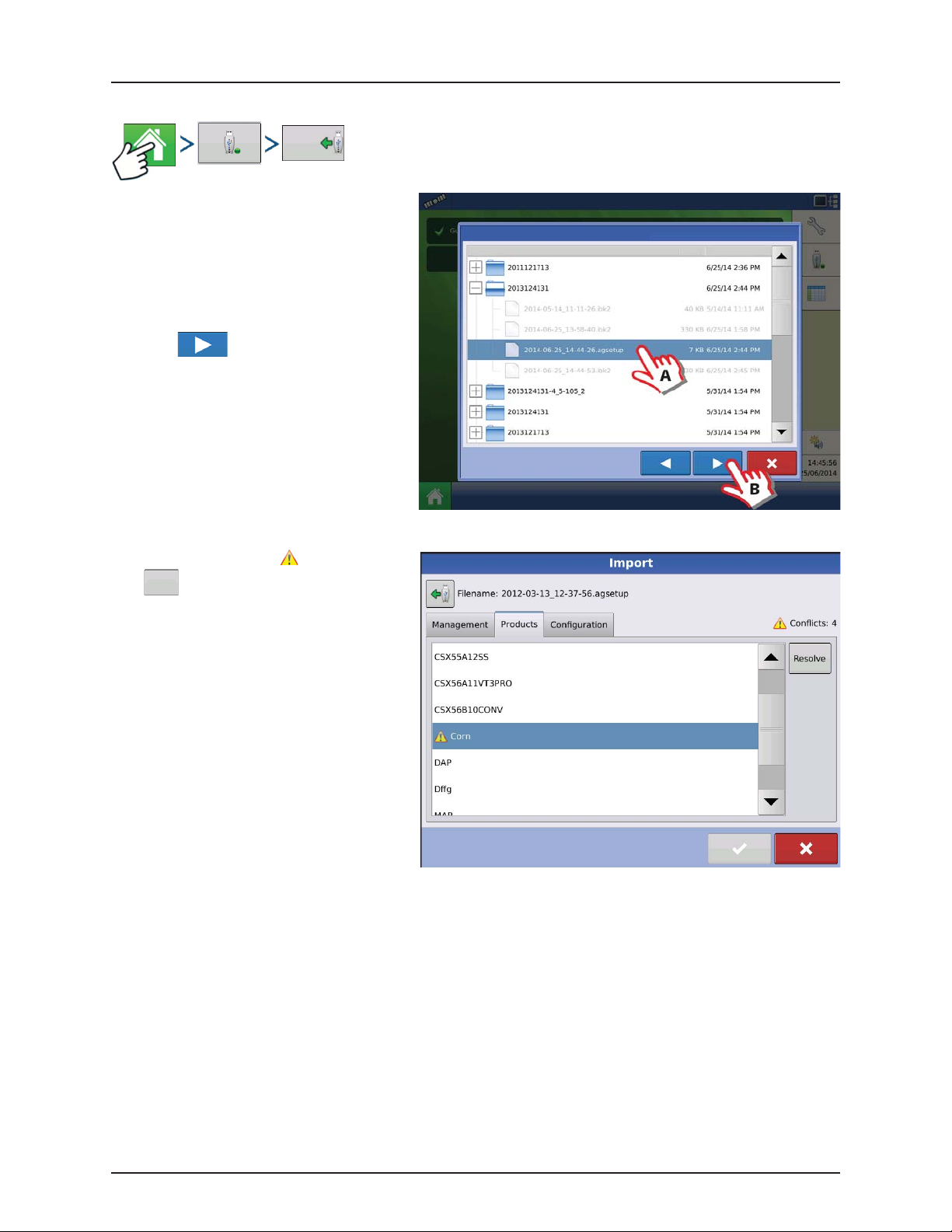
Import Setup Data
Import
Files
Use the scroll bar to find the file you wish to
import.
When a setup file is created, it is saved in a folder
titled with the displays serial number _nickname.
The file will include a date and have the .agsetup
suffix.
A. Select desired setup file from directory.
B. Press to continue.
Import Setup: Select AgSetup File
Name Size Date Modified
Highlight item with conflict
Press .
.
4.14
Page 41
Conflicts can be resolved by:
• Rename Import
• Rename Existing
• Merge
Product Mixes and Configurations can not be
merged. The Merge button will be grayed out and
not selectable for these items.
Once all conflicts have been resolved.
Press .
Home Screen
Name:
Modification Time:
Creation Time:
4 - System setup
Conflict Resolution
Item to Import Existing Item
Corn Name:
Modification Time:
Creation Time:
Rename
Imported
Rename the item being imported.
Rename
Rename the existing Item.
Existing
Merge
Merge the imported and existing items together.
Corn
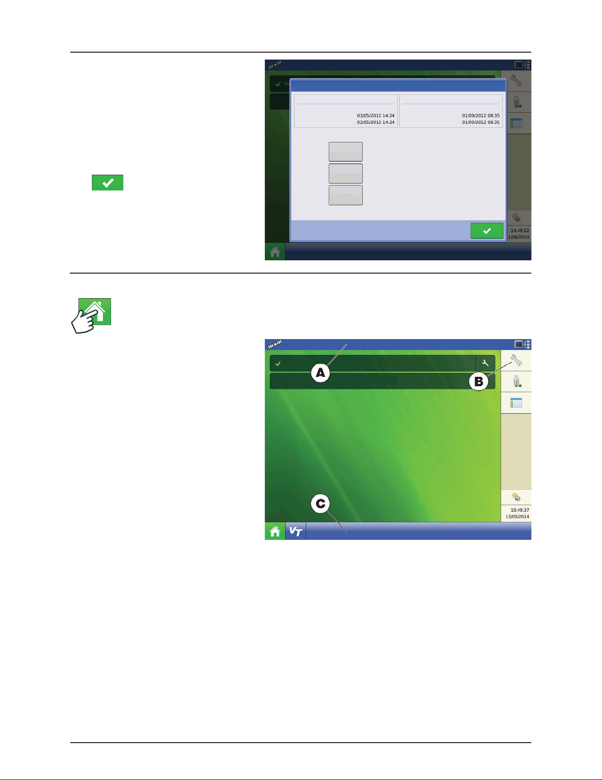
Most of the functionality of the display is not
available until the basic setup process is
completed.
A. Status bar.
Guidance
Select Event
B. Setup button.
C. Task bar.
You must complete these initial configuration
steps for the Run Time Environment to be active:
ATTENTION! It is strongly recommended to
set up the controller by using the “Quick
Setup Guide” on page 4.16.
• Grower, Farm, and Field management.
For more information, See “Management
button” on page 4.51.
• Equipment Operating Configuration.
You can access Configuration Setup by pressing the Setup (wrench) button (B) at the upper right-hand portion of the
Home screen. For more information, see “Configuration button” on page 4.49.
• Product setup.
For more information, see “Product tab” on page 4.50, as well as the additional configuration information described
in each Operations chapter.
• Start Field Operation.
For more information, “Configuration Setup Screen” on page 5.1.
4.15
Page 42

4 - System setup
Quick Setup Guide
General Info
For a quick and easy start with your new HC 8500/9500 controller, it is strongly recommended to set up the controller by
using this quick setup guide.
To change settings later, or for a more in-depth explanation of settings, please refer to the following parts of this chapter.
Sprayer Types
The following configuration is split into two parts, depending on the sprayer type:
• Trailer and Lift sprayers. See “Configuration for Trailer and Lift sprayers” on page 4.16 (below).
ATTENTION! As this part covers both Trailer and Lift sprayers, please note that some steps may vary, as some do not
appear while others may be specific to your sprayer type.
• Self-Propelled sprayer. See “Configuration for Self-Propelled sprayers” on page 4.33.
Configuration for Trailer and Lift sprayers
1. At the HC9500 Home Screen, press to
enter the Configuration Setup.
Guidance
Select Event
2. Press to add a Configuration.
4.16
Configuration
Product
Configuration Setup
Equipment
Equipment
Name
Page 43
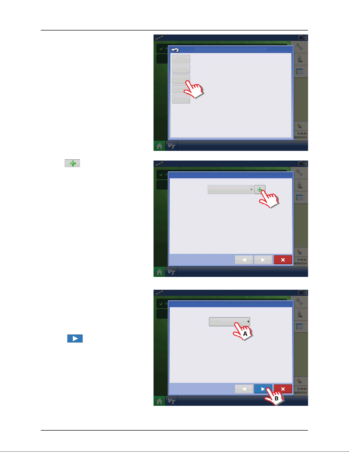
3. Press “Application” to create an application
setup.
4 - System setup
Choose Operating Configuration Type
Tillage
Create a tillage operating configuration for coverage logging and guidance-only
operations.
Planting Create a planting operating configuration.
4. Press to select a vehicle.
Application
Surveying
Operating Configuration Wizard: Vehicle
Create a liquid and granular application, or strip-till operating configuration.
Harvest
harvest grain yield monitoring operating configuration.
Create a surveying operating configuration to record ground elevation.
Select Vehicle
5. Vehicle Type:
A. Select “Tractor”.
ATTENTION! Lift sprayers must also select
“Tractor”.
B. When “Tractor” is selected, press
to confirm.
Vehicle Wizard: Vehicle Type
Vehic le Type
Tract or
Create New Vehicle
4.17
Page 44

4 - System setup
6. Enter Vehicle Information:
A. Press the “Make” to type in the
vehicle name.
B. Press the “Model” to type in
the vehicle model.
C. Press to confirm.
7. Enter distance from Rear Axle of the tractor to
the following locations:
• “Rear Drawbar” for a trailer sprayer.
• “Rear Lift Arms” for a lift sprayer.
ATTENTION! The option “Front Lift Arms” is
not used for HARDI® sprayers.
Trailer as example:
A. Chose “Rear drawbar”.
B. Press to type in value.
C. Press .
Vehicle Wizard: Make and Model
Enter Vehicle Information
Make
Model
Vehicle Wizard: Attachment points
Enter Distance from Rear Axle to the following Locations
Rear Drawbar
Rear Lift Arms
Front L ift Arm s
8. Vehicle Name:
A. Press the button to change the
vehicle name, if necessary.
B. Press to confirm selection.
4.18
Vehicle Wizard: Vehicle Name
Enter Vehicle Name
JD 4630
Page 45

9. Antenna Settings:
Press the button to change the antenna
settings for the Selected Vehicle in the drop
down menu.
10. Enter Distance from Antenna location to Rear
Axle:
A. Choose “In Front” or “Behind” from the
Rear axle.
B. Press to type in the measured
value for the GPS Front/Back Offset
from the vehicle.
Operating Configuration Wizard: Vehicle
Select Vehicle
JD 4630
Offsets
Antenna Location from Rear Axle
Antenna Location from Centerline
Antenna Height from Ground
Rear Drawbar
Rear Lift Arms
Front L ift Ar ms
Vehicle Offsets: JD 4630
Antenna
Hitch
Enter Distance from Vehicle References to the Antenna
Antenna Location from
Rear Axle
Antenna Location from
Centerline
Antenna Height from
Ground
4 - System setup
In Front
Left
11. Enter Distance from Antenna location to
Center line:
A. Choose “Left” or “Right” from the
Center line.
B. Press to type in value.
Antenna
Vehicle Offsets: JD 4630
Hitch
Enter Distance from Vehicle References to the Antenna
Antenna Location from
Rear Axle
Antenna Location from
Centerline
Antenna Height from
Ground
In Front
Left
4.19
Page 46

4 - System setup
12. Enter Distance from Antenna Height to
Ground:
A. Press to type in value.
B. Press to confirm selection.
13. Hitch Settings:
A. Press Hitch to view data already typed
in step 7.
B. Press to confirm selection.
Antenna
Antenna
Vehicle Offsets: JD 4630
Hitch
Enter Distance from Vehicle References to the Antenna
Antenna Location from
Rear Axle
Antenna Location from
Centerline
Antenna Height from
Ground
Vehicle Offsets: JD 4630
Hitch
Enter Distance from Rear Axle to the Following Locations
Rear Drawbar
In Front
Left
14. Check the data in the overview.
Press to confirm selection.
ATTENTION! If Offsets need to be corrected,
then press the button to change the
antenna settings for the Selected Vehicle in
the drop down menu, before confirming
selection.
Rear Lift Arms
Front L ift Arm s
Operating Configuration Wizard: Vehicle
Select Vehicle
JD 4630
Offsets
Antenna Location from Rear Axle
Antenna Location from Centerline
Antenna Height from Ground
Rear Drawbar
Rear Lift Arms
Front Li ft Arms
4.20
Page 47

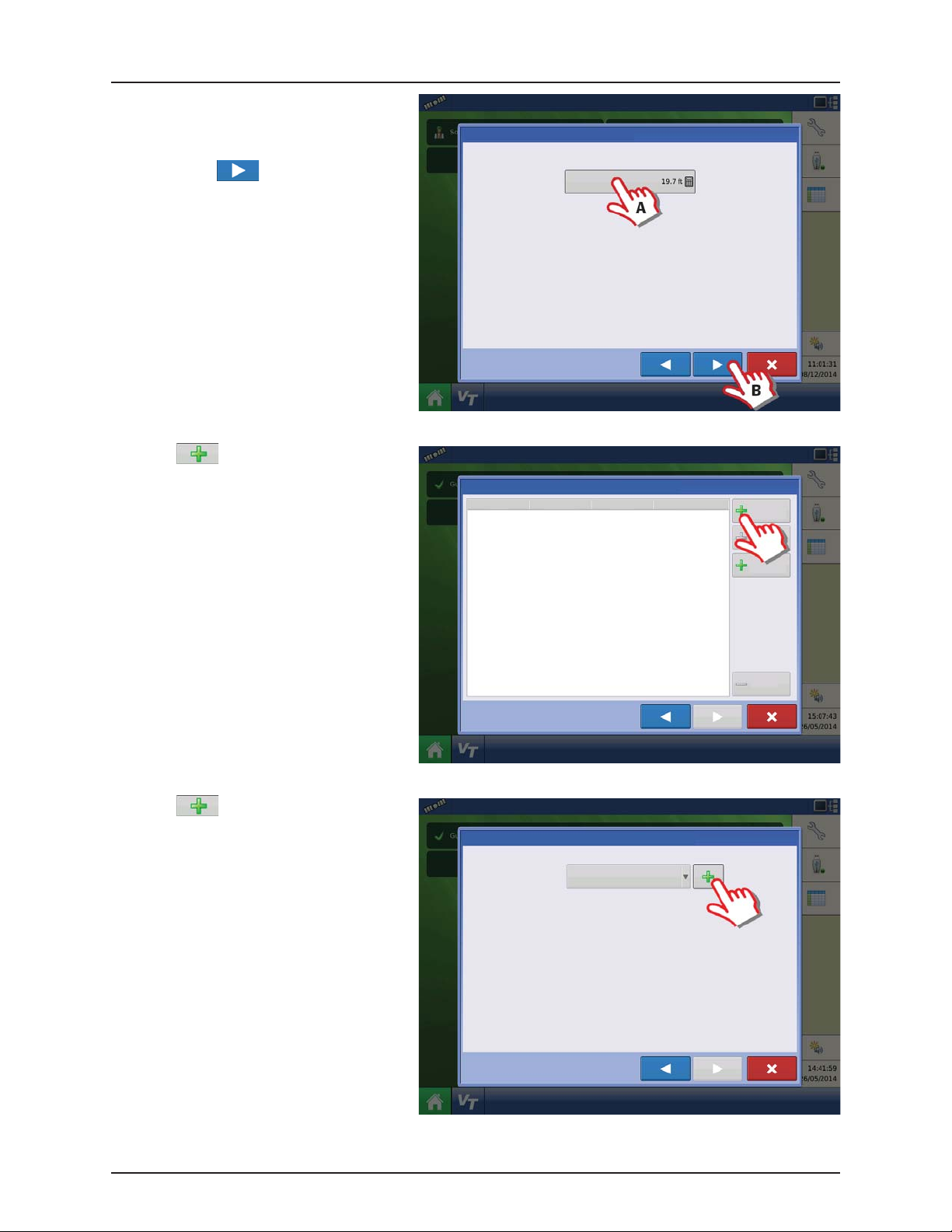
15. Create Implement by pressing the
button.
16. Implement Information:
A. Press the “Make” to type in the
implement name.
B. Press the “Model” to type in
the implement model.
C. Press to confirm.
4 - System setup
Operating Configuration Wizard: Implement
Select Implement
Implement Wizard: Make and Model
Enter Implement Information
Make
Hardi
Model
Commander
17. Attachment Type:
A. Select Implement Attachment Type:
• “Rear Drawbar” for a trailer sprayer.
• “Rear Lift Arms” for a lift sprayer.
ATTENTION! The option “Front Lift Arms” is
not used for HARDI® sprayers.
B. Press to confirm selection.
Implement Wizard: Attachment Type
Implement Attachment Type
Rear Drawbar
4.21
Page 48
4 - System setup
18. Trailer sprayer only:
A. Select to Enter Hitch to Implement
Distance:
B. Press to confirm selection.
19. Press Liquid Application to create an
Application Channel.
Implement Wizard: Axle Offsets
Enter Hitch to Implement Axle Dista nce
Implement Wizard: Application Channels
Type Controller Channel Container
Liquid
Application
20. Press to add an Application Rate
Controller.
Equipment Setup Wizard: Rate Controller
Select Application Rate Controller
No Controller
Granular
Application
Remove
4.22
Page 49

21. Press “Device” drop down menu to select
“ISOBUS” for a HARDI® sprayer.
22. Device drop down menu will change to
ISOBUS.
Press to confirm selection.
4 - System setup
Controller Setup Wizard: Device
Select Controller or Flow Meter
Device
DirectCommand
Direct Type
Liquid Product Control
Controller Setup Wizard: Device
Select Controller or Flow Meter
23. Select Controller Make:
A. Select “Hardi” in the “Make” drop
down menu.
After selection, the “Model” drop
down menu will disappear.
B. Check the “Supports Rate Control” box
to enable the HARDI® VT rate control
function.
C. Press to confirm selection.
Device
ISOBUS
Controller Setup Wizard: Make and Model
Select Controller Make and Model
Make
Hardi
Supports Rate Control
4.23
Page 50
4 - System setup
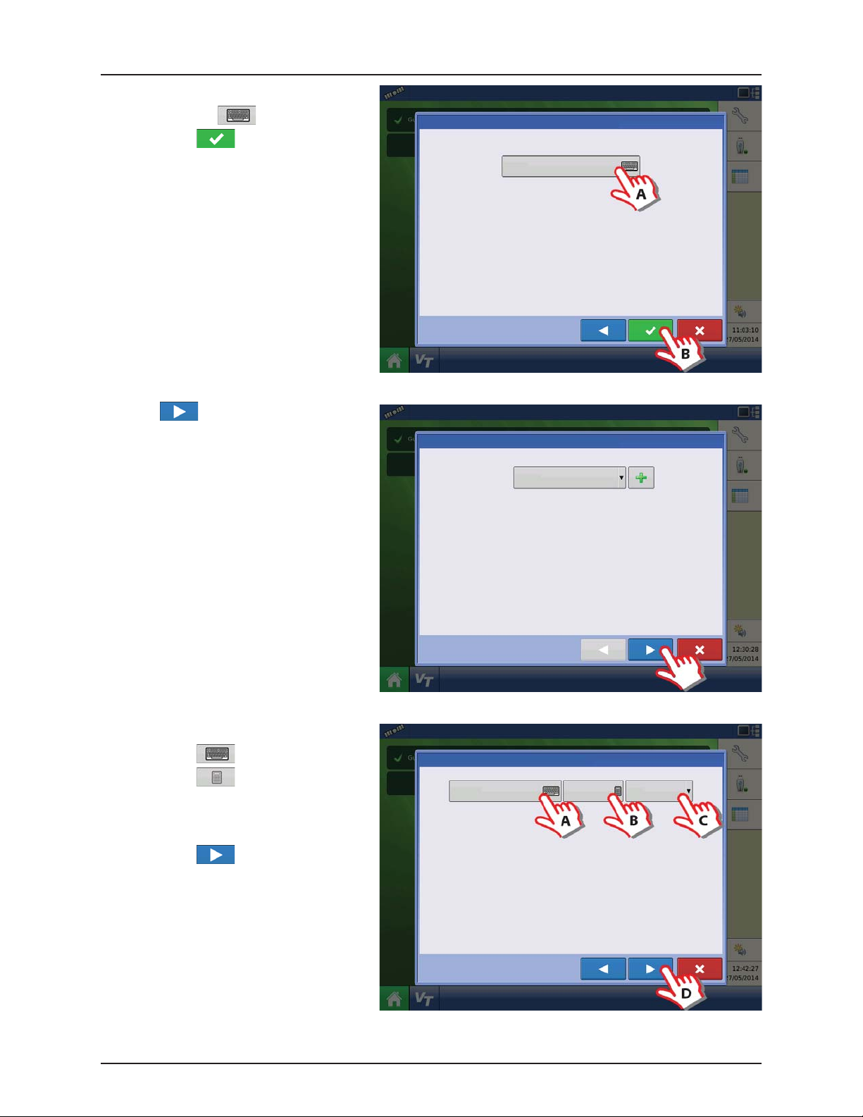
24. Controller Name:
A. Press the to change the name.
B. Press to save the name.
25. Press to confirm selection.
Controller Setup Wizard: Controller Name
Controller Name
Hardi
26. Container (Main Tank) setup:
A. Press to change name.
B. Press to enter true container
capacity.
C. Press drop down menu to change
units.
D. Press to confirm.
Equipment Setup Wizard: Rate Controller
Equipment Setup Wizard: Container
Container Name Capacity Units
Main Tank
Select Application Rate Controller
Hardi
2000
Gallons
4.24
Page 51

27. Enter Number of Boom Sections:
A. Press the arrows to set number of
sections on the sprayer.
ATTENTION! This value must be the same as
typed in the HARDI® VT menu 3.3.3
B. Press to confirm selection.
28. Enter Full Swath (Boom) Width:
A. Press to type in the value.
ATTENTION! If the value is not the same as in
the HARDI® VT menu 3.3.1 an ISOBUS
warning will appear.
B. Press to confirm selection.
Equipment Setup Wizard: Section Count
TIP: DO NOT enter the number of individual rows. For most
implements, enter the number of swath sections that can be
independently turned on and off.
Equipment Setup Wizard: Swath Width
Enter Number of Boom Sections
Enter Full Swath Width
4 - System setup
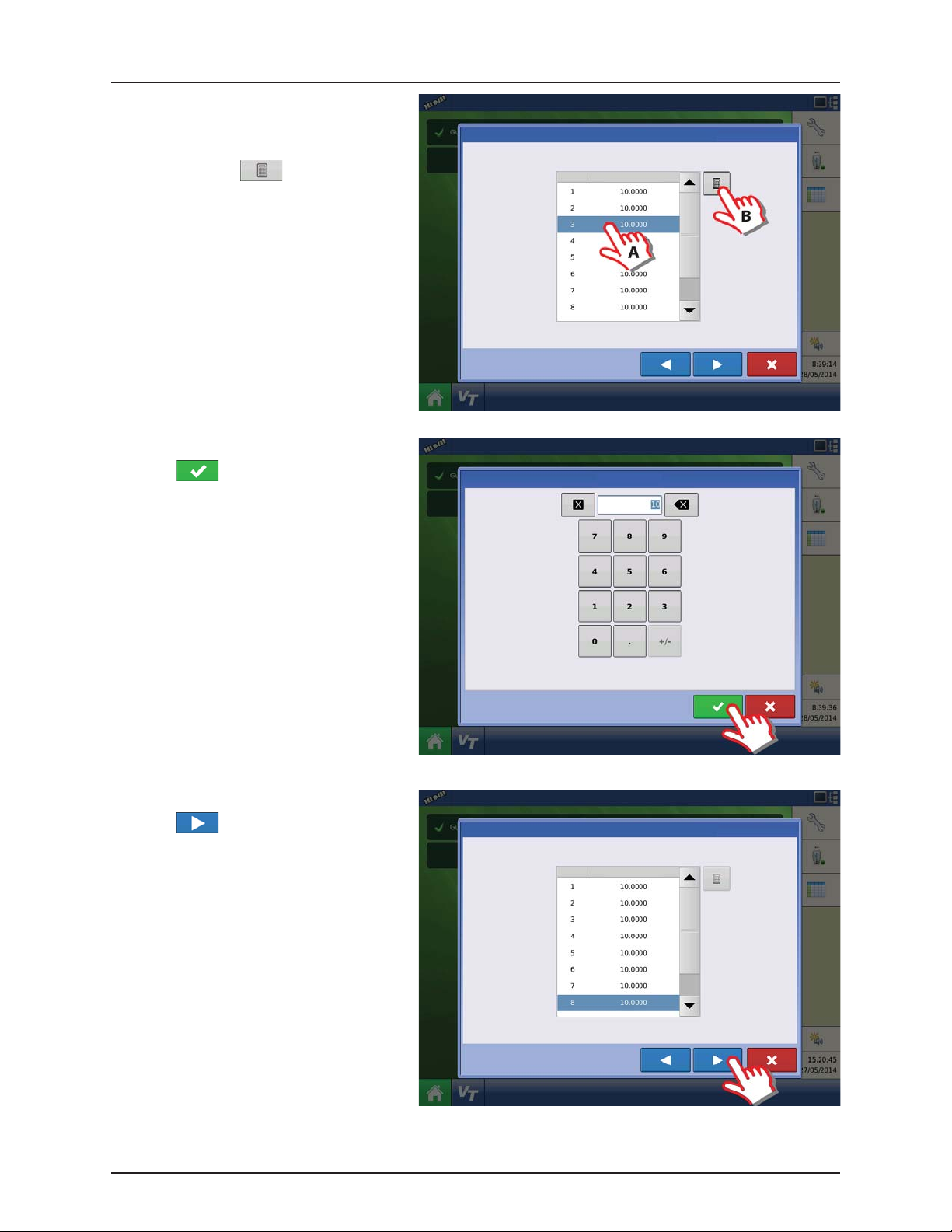
29. Edit Boom Section Widths from Left to Right:
NOTE! If number of sections and boom
÷
widths (swath widths) are already correct,
then press to confirm selection.
Then continue this guide from step 32.
ATTENTION! These values must be the same
as typed in the HARDI® VT menu 3.3.3.1 to
3.3.3.x
TIP: For tillage implements, enter the working swath width
(actual implement width minus the typical overlap). This
results in a more accurate area calculation.
Equipment Setup Wizard: Section Configuration
Enter Boom Section Widths from Left to Right
Section Swath Width (ft)
TIP: The implement is divided into equal section sizes by default. To
modify the sections, press the keypad button for each section that
needs to be changed.
4.25
Page 52
4 - System setup
30. Edit Boom Section Widths from Left to Right.
A. Press on the Section you wish to edit
to highlight it.
B. Press the button to change to
the right section width.
31. Type in the section width.
Press to confirm the value.
Equipment Setup Wizard: Section Configuration
Enter Boom Section Widths from Left to Right
Section Swath Width (ft)
TIP: The implement is divided into equal section sizes by default. To
modify the sections, press the keypad button for each section that
needs to be changed.
Boom Width
32. When all Sections are changed:
Press to confirm selection.
4.26
Equipment Setup Wizard: Section Configuration
Enter Boom Section Widths from Left to Right
Section Swath Width (ft)
TIP: The implement is divided into equal section sizes by default. To
modify the sections, press the keypad button for each section that
needs to be changed.
Page 53

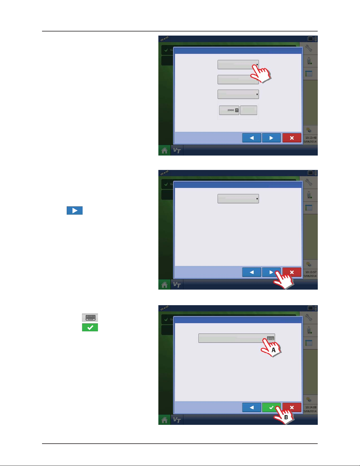
33. Application Point Offset:
A. Press to enter the distance
from the tractor hitch to the nozzles
on the sprayer.
B. Press to confirm value.
ATTENTION! For offsets see “Sprayer Offsets”
on page 8.1.
34. Press to confirm selection.
4 - System setup
Equipment Setup Wizard: Application Point Offset
Implement Wizard: Application Channels
Type Controller Channel Container
Liquid Hardi Main Tank
Enter Distance from Hitch to Application Point
(front to back)
Liquid
Application
Direct
Injection
Granular
Application
35. Additional devices:
A. Press “Norac UC5” button to enable
the use of
AutoTerrain/AutoHeight/AutoSlant.
B. Press to continue.
ATTENTION! If the “Norac UC5” is not
enabled, the
AutoTerrain/AutoHeight/AutoSlant will not
be shown in the working screen.
Implement Wizard: Additional Devices
Norac UC5
OptRx Crop Sensor
Crop Sensor Settings
Sensing Width
Swath
Offsets
Note: Sensing Width should typically be set to the same
width as the implement.
Number of Sensors
Remove
4.27
Page 54

4 - System setup
36. Press to continue.
ATTENTION! Settings here not relevant for
HARDI® Trailer and Lift sprayers!
37. Enter Implement Name:
A. Press button to change name.
B. Press to confirm name.
Implement Wizard: Hitch Point Configuration
Enter Hitch Point Information
Implement Provides a Rear Hitch
Enter Left or Right Distance
to the left
Enter Forward or Backward Distance
Enter the left or right offset and the forward or backward
distance from the point the implement connects to a vehicle
to the implement’s hitch point.
Implement Wizard: Implement Name
Enter Implement Name
Hardi Commander
38. Select the specific implement to be setup in
the pull down menu.
Press to confirm the selection.
4.28
Operating Configuration Wizard: Implement
Select Implement
Hardi Commander
Equipment Name
Implement Hardi Commander
Device
Container
Device
Hardi
Main Tank
Boom Height
Page 55
39. Select Primary Speed Source.
• Trailer sprayer with SafeTrack/IntelliTrack:
Must always use “Hardi” as speed source as
the steering system cannot use GPS as
speed source.
• Lift mounted sprayer:
Can select between “Display GPS” or
“Auxiliary Device” as speed source.
NOTE! If “Display GPS” is selected, the “Hardi”
÷
option must be selected as backup source.
ATTENTION! For additional information see
“Speed Input Settings” on page 4.70.
40. “Hardi” is now selected as Primary Source.
4 - System setup
Operating Configuration Wizard: Speed Source
Primar y Source
Display GPS
Backup Source
Auxiliary Device
Auxiliary Device Channel
Radar
Auxiliary Channel Calibration
Calibrate
Distance
Pulses / 100 ft
ATTENTION! No other source can be
selected when “Hardi” is selected as primary
source.
Press to confirm the selection.
41. Suggested Name for Configuration:
A. Press button to change name.
B. Press to confirm selection.
Operating Configuration Wizard: Speed Source
Primar y Source
Hardi
Operating Configuration Wizard: Configuration Name
Suggested Name for Configuration
JD 4630, Hardi Commander
4.29
Page 56

4 - System setup
42. Overview of Configuration Setup with a
Trailed sprayer as example:
Vehicle: JD 4630.
Implement: Hardi Commander.
• Device: Hardi
• Container: Main Tank
• Device: Boom Height
43. Press to edit the configuration.
Configuration Product
Application
JD 4630, Hardi Commander
Configuration Product
Application
JD 4630, Hardi Commander
Configuration Setup
Vehicle JD 4630
Implement Hardi Commander
Configuration Setup
Vehicle JD 4630
Implement Hardi Commander
Equipment Name
Device
Container
Device
Equipment Name
Device
Container
Device
Hardi
Main Tank
Boom Height
Hardi
Main Tank
Boom Height
Equipment
Equipment
44. Trailer sprayers only:
Press “Offsets” to edit the configuration.
4.30
Vehicle
JD 4630
Automatic
Swath Control
Equipment
Vehic le
Offsets
Speed
Input
Auxiliary
Input
Settings
Configuration Setup
1
Implement: Hardi Commander Controller: Hardi ISOBUS
Full Swath:
Sections:
Norac
Offsets
UC5
120 ft12Device:
Make:
Hardi International A/S
ISOBUS
Page 57

45. Trailer sprayers only:
A. If applicable, select “Hardi SafeTrack”
as implement Type.
ATTENTION! For IntelliTrack sprayers, select
the “Hardi SafeTrack” option.
B. Press to type in the measured
distance from Hitch to the axle of the
sprayer.
C. Press to confirm.
50. Press “Automatic Swath Control” to edit the
configuration.
Implement Offsets: Hardi Commander
Implement Liquid with Hardi ISOBUS
Implement Modeling
Implement Type
Hardi SafeTrack
Implement Rear Hitch
Implement Provides a Rear Hitch
Front Hitch to Rear Hitch
Configuration Setup
Vehicle
JD 4630
Vehic le
Offsets
1
Implement: Hardi Commander Controller: Hardi ISOBUS
Full Swath:
Sections:
Boom Control
Hitch to Axle
Distance
4 - System setup
Heading
Aggressivene ss
Lateral Offset from Centerline
Left
120 ft12Device:
Make:
Hardi International A/S
ISOBUS
Speed
Input
Auxiliary
Input
Automatic
Swath Control
Equipment
Settings
Norac
UC5
Offsets
4.31
Page 58
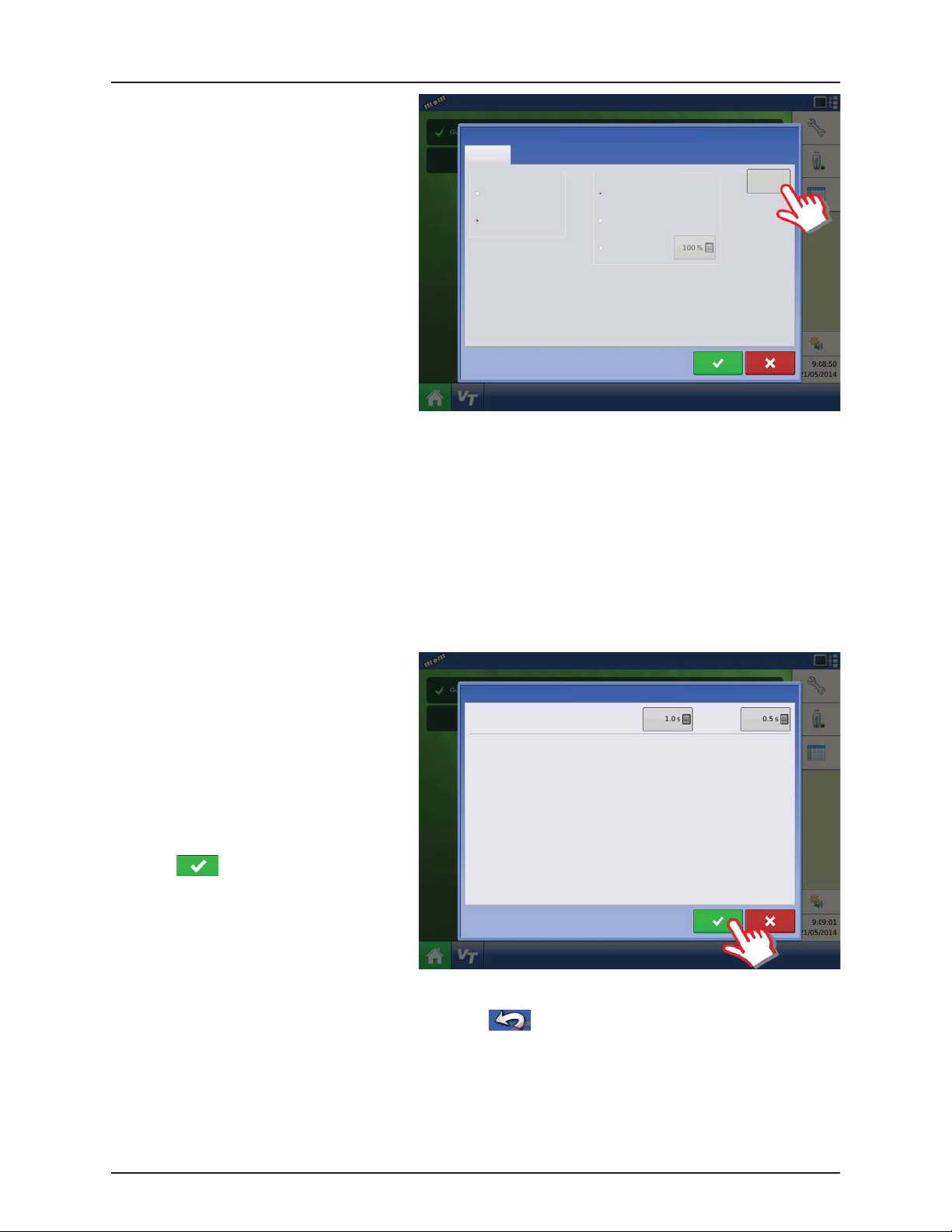
4 - System setup
51. Automatic Swath Control options:
• Outside Boundary Option
Select one of the two options to determine
system behavior when a section exits a field
boundary.
• Coverage Option
In the Coverage Option area, you must
choose between three options:
• Minimize Skip
Turns off the implement section after
the entire section is fully inside your
coverage area.
This prevents the possibility of skips.
• Minimize Overlap
Turns off the implement section when
that section first enters your coverage
area.
This prevents the possibility of overlaps.
• User Defined
Allows you to choose what percentage of the implement section is within the coverage area before that section
turns off. For example, if you choose 50%, then the section will switch off when half of it is within your coverage
area.
• Press “Look Ahead Settings” to edit settings.
Application
Outside Boundary Option
Keep Unchanged
Turn Sect ion O ff
Automatic Swath Control
Coverage Option
Minimize Skip
Minimize Overlap
User Defined
Look-Ahead
Settings
52. Look Ahead settings:
• Turn-On Look Ahead
Determines how far ahead the system looks
to turn the sections back on. This
compensates for delay in the system when
Hardi Turn-On: Turn-Off :
Look Ahead Settings
the sprayer sections are turned on.
• Turn-Off Look Ahead
Determines how far ahead the system looks
to turn the sections off. This compensates for
delay in the system when the sections are
turned off.
Press to confirm.
53. When returned to Configuration Setup screen, then press in order to continue with “Product setup” on
page 4.46.
4.32
Page 59
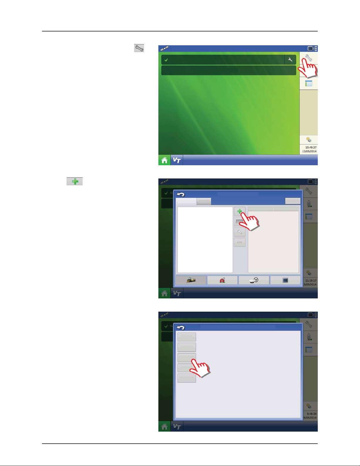
Configuration for Self-Propelled sprayers
1. At the HC9500 Home Screen, press to
enter the Configuration Setup.
2. Press to add a Configuration.
Guidance
Configuration
Product
Select Event
Configuration Setup
4 - System setup
Equipment
Equipment
Name
3. Press “Application” to create an application
setup.
Choose Operating Configuration Type
Tillage
Create a tillage operating configuration for coverage logging and guidance-only
operations.
Planting Create a planting operating configuration.
Application
Surveying
Create a liquid and granular application, or strip-till operating configuration.
Harvest
harvest grain yield monitoring operating configuration.
Create a surveying operating configuration to record ground elevation.
4.33
Page 60

4 - System setup
4. Press to select a vehicle.
5. Select “Self-Propelled Applicator”.
Operating Configuration Wizard: Vehicle
Select Vehicle
Vehicle Wizard: Vehicle Type
Create New Vehicle
Vehic le Type
Tract or
6. When Self-Propelled Applicator is selected:
A. Check this box if All-Wheel Steer is
applicable and will be used when
spraying.
B. Press to confirm.
ATTENTION! Checking the “All-Wheel Steer”
option activates logging of 4 wheel steering
for AutoSectionControl.
4.34
Vehi cle Wi zard: Vehicl e Type
Create New Vehicle
Vehicle Type
Self-Propelled Applicator
All-Wheel Steer
Page 61

7. Enter Vehicle Information:
A. Press the “Make” to type in the
vehicle name.
B. Press the “Model” to type in
the vehicle model.
C. Press to confirm.
8. Press Liquid Application to create an
Application Channel.
Vehicle Wizard: Make and Model
Enter Vehicle Information
Make
Model
Implement Wizard: Application Channels
Type Controller Channel Container
4 - System setup
Liquid
Application
9. Press to add a Application Rate
Controller.
Equipment Setup Wizard: Rate Controller
Select Application Rate Controller
No Controller
Granular
Application
Remove
4.35
Page 62
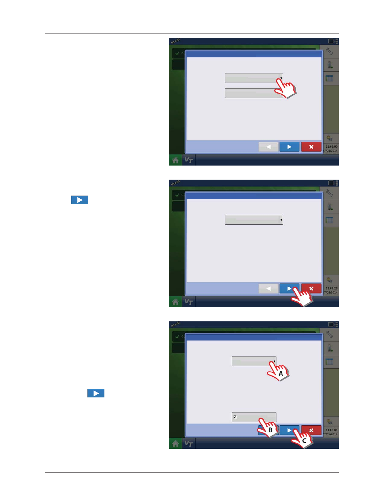
4 - System setup
10. Press “Device” drop down menu to select
“ISOBUS” for a HARDI® sprayer.
11. Direct Type drop down menu will change to
ISOBUS.
Press to confirm selection.
Controller Setup Wizard: Device
Select Controller or Flow Meter
Device
DirectCommand
Direct Type
Liquid Product Control
Controller Setup Wizard: Device
Select Controller or Flow Meter
12. Select Controller Make:
A. Select “Hardi” in the “Make” drop
down menu.
By selection the “Model” drop down
menu will disappear.
B. Check the “Supports Rate Control” box
to enable the HARDI® VT rate control
function.
C. Press to confirm selection.
Device
ISOBUS
Controller Setup Wizard: Make and Model
Select Controller Make and Model
Make
Hardi
4.36
Supports Rate Control
Page 63

13. Controller Name:
A. Press the to change the name.
B. Press to save the name.
14. Press to confirm selection.
4 - System setup
Controller Setup Wizard: Controller Name
Controller Name
Hardi
15. Container (Main Tank) setup:
A. Press to change name.
B. Press to enter true container
capacity.
C. Press drop down menu to change
units.
D. Press to confirm.
Equipment Setup Wizard: Rate Controller
Equipment Setup Wizard: Container
Container Name Capacity Units
Main Tank
Select Application Rate Controller
Hardi
1300
Gallons
4.37
Page 64
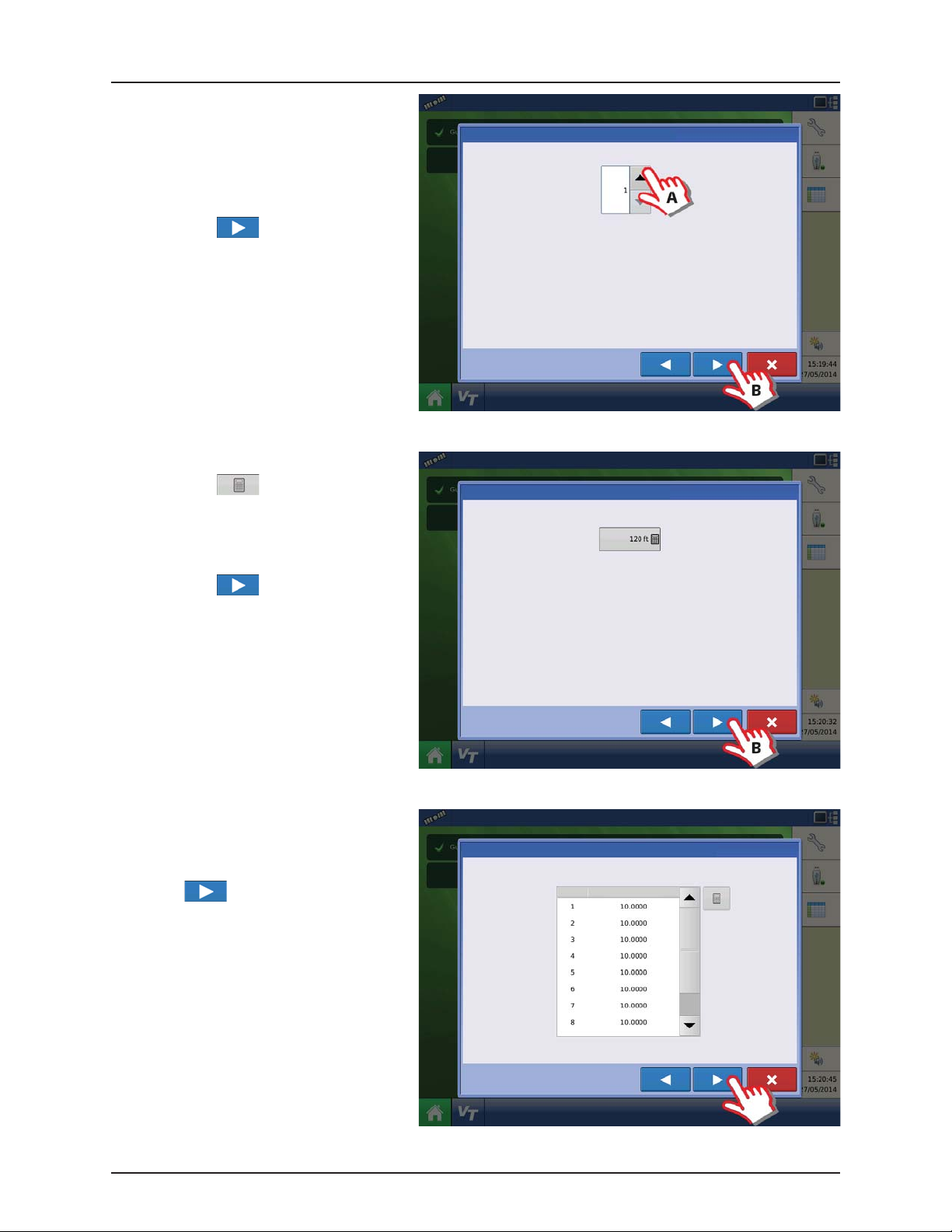
4 - System setup
16. Enter Number of Boom Sections:
A. Press the arrows to set number of
sections on the sprayer.
ATTENTION! This value must be the same as
typed in the HARDI® VT menu 3.3.3
B. Press to confirm selection.
17. Enter Full Swath (Boom) Width:
A. Press to type in the value.
ATTENTION! If the value is not the same as in
the HARDI® VT menu 3.3.1 an ISOBUS
warning will appear.
B. Press to confirm selection.
Equipment Setup Wizard: Section Count
TIP: DO NOT enter the number of individual rows. For most
implements, enter the number of swath sections that can be
independently turned on and off.
Equipment Setup Wizard: Swath Width
Enter Number of Boom Sections
Enter Full Swath Width
18. Edit Boom Section Widths from Left to Right:
NOTE! If number of sections and boom
÷
widths (swath widths) are already correct,
press to confirm selection. Then skip
to step 22.
ATTENTION! These values must be the same
as typed in the HARDI® VT menu 3.3.3.1 to
3.3.3.x
TIP: For tillage implements, enter the working swath width
(actual implement width minus the typical overlap). This
results in a more accurate area calculation.
Equipment Setup Wizard: Section Configuration
Enter Boom Section Widths from Left to Right
Section Swath Width (ft)
TIP: The implement is divided into equal section sizes by default. To
modify the sections, press the keypad button for each section that
needs to be changed.
4.38
Page 65

19. Edit Boom Section Widths from Left to Right.
A. Press on the Section you wish to edit
to highlight it.
B. Press the button to change to
the right section width.
20. Type in the section width.
Press to confirm the value.
4 - System setup
Equipment Setup Wizard: Section Configuration
Enter Boom Section Widths from Left to Right
Section Swath Width (ft)
TIP: The implement is divided into equal section sizes by default. To
modify the sections, press the keypad button for each section that
needs to be changed.
Boom Width
21. When all Sections are changed:
Press to confirm selection.
Equipment Setup Wizard: Section Configuration
Enter Boom Section Widths from Left to Right
Section Swath Width (ft)
TIP: The implement is divided into equal section sizes by default. To
modify the sections, press the keypad button for each section that
needs to be changed.
4.39
Page 66
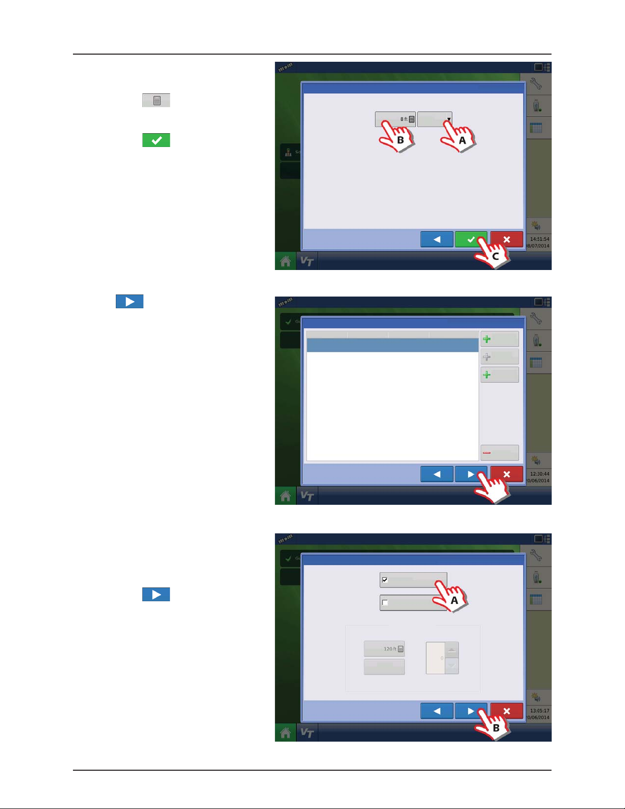
4 - System setup
22. Application Point Offset:
A. Press to select “Behind”.
B. Press to enter the distance
from the rear axle of the vehicle to the
nozzles on the sprayer.
C. Press to confirm.
ATTENTION! For offsets see “Sprayer Offsets”
on page 8.1.
23. Press to confirm selection.
Equipment Setup Wizard: Application Point Offset
Enter Distance from Rear Axle to Application Point
Behind
Implement Wizard: Application Channels
Type Controller Channel Container
Liquid Hardi Main Tank
Liquid
Application
Direct
Injection
Granular
Application
24. Additional devices:
A. Press “Norac UC5” button to enable
the use of
AutoTerrain/AutoHeight/AutoSlant.
B. Press to continue.
ATTENTION! If the “Norac UC5” is not
enabled, the
AutoTerrain/AutoHeight/AutoSlant will not
be shown in the working screen.
Implement Wizard: Additional Devices
Norac UC5
OptRx Crop Sensor
Crop Sensor Settings
Sensing Width
Swath
Offsets
Note: Sensing Width should typically be set to the same
width as the implement.
Number of Sensors
Remove
4.40
Page 67

25. Enter Vehicle Name:
A. Press button to change name.
B. Press to confirm name.
26. Press to enter values for Antenna Offsets.
4 - System setup
Implement Wizard: Vehicle Name
Enter Vehicle Name
Hardi Saritor
27. Vehicle Offsets:
A. Press to enter Antenna Location from
Rear Axle.
B. Select if the Antenna is In Front or
Behind the Rear Axle.
C. Press to enter Antenna Location from
the sprayers center line.
D. Select if the Antenna is to the Left or
Right of the sprayers center line.
E. Press to enter Antenna Height from
Ground.
F. Press “Steering” to continue with
Steering Type selection.
Operating Configuration Wizard: Vehicle
Offsets
Antenna Location from Rear Axle
Antenna Location from Centerline
Antenna Height from Ground
Dispensing Location from Rear Axle
Dispensing Location from Centerline
Vehicle Offsets: Hardi Saritor
Antenna
Steering
Enter Distance from Vehicle References to the Antenna
Enter Location from
Rear Axle
Enter Location from
Centerline
Antenna Height from
Ground
Select Vehicle
Behind
In Front
Left
4.41
Page 68

4 - System setup
28. Press to confirm the settings and
continue.
29. Select Primary Speed Source.
• Self-Propelled sprayer:
Can select between “Hardi” or “Display GPS”
as speed source.
• SARITOR sprayer only:
Always select “Display GPS” as speed source.
NOTE! If “Display GPS” is selected, the “Hardi”
÷
option must be selected as backup source.
ATTENTION! For additional information see
“Speed Input Settings” on page 4.70.
Operating Configuration Wizard: Vehicle
Offsets
Antenna Location from Rear Axle
Antenna Location from Centerline
Antenna Height from Ground
Dispensing Location from Rear Axle
Dispensing Location from Centerline
Operating Configuration Wizard: Speed Source
Select Vehicle
Primar y Source
Display GPS
Backup Source
Auxiliary Device
Auxiliary Device Channel
Radar
Auxiliary Channel Calibration
Calibrate
Distance
Pulses / 100 ft
In Front
Behind
30. “Hardi” is now selected as Primary Source.
ATTENTION! No other source can be
selected when “Hardi” is selected as primary
source.
Press to confirm the selection.
4.42
Operating Configuration Wizard: Speed Source
Primar y Source
Hardi
Page 69

31. Suggested Name for Configuration:
A. Press button to change name.
B. Press to confirm selection.
32. Overview of Configuration Setup:
Vehicle: Hardi Saritor
• Device: Hardi
• Container: Main Tank
• Device: Boom Height
ATTENTION! A Self-Propelled sprayer will
have no implement information.
4 - System setup
Operating Configuration Wizard: Configuration Name
Hardi Saritor
Configuration Product
Application
Hardi Saritor
Suggested Name for Configuration
Configuration Setup
Equipment Name
Vehicle Hardi S aritor
Device
Container
Device
Hardi
Main Tank
Boom Height
Equipment
33. Press to edit the configuration.
Configuration Product
Application
Hardi Saritor
Configuration Setup
Vehicle Hardi S aritor
Equipment Name
Device
Container
Device
Hardi
Main Tank
Boom Height
Equipment
4.43
Page 70

4 - System setup
34. Press “Offsets” to edit the configuration.
35. Implement Offsets:
A. Press to change value.
B. Press to confirm.
Vehicle
Hardi Saritor
Vehic le
Offsets
Speed
Input
Auxiliary
Input
Automatic
Swath Control
Equipment
Settings
Liquid with Hardi
Configuration Setup
1
Implement: Hardi Sar itor Controller: Hardi ISOBUS
Full Swath:
Sections:
Norac
Offsets
UC5
120 ft12Device:
Make:
Hardi International A/S
Implement Offsets: Hardi Saritor
Boom Height
Forward/Backward Distance from Rear Axle
8 ft Behind
ISOBUS
36. Press “Automatic Swath Control” to edit the
configuration.
Vehicle
Hardi Saritor
Auxiliary
Automatic
Swath Control
Equipment
Settings
Vehic le
Offsets
Speed
Input
Input
Left/Right Distance from Centerline
Left
Configuration Setup
1
Implement: Hardi Sar itor Controller: Hardi ISOBUS
Full Swath:
Sections:
Norac
Offsets
UC5
120 ft12Device:
Make:
Hardi International A/S
ISOBUS
4.44
Page 71

37. Automatic Swath Control options:
• Outside Boundary Option
Select one of the two options to determine
system behavior when a section exits a field
boundary.
• Coverage Option
In the Coverage Option area, you must
choose between three options:
• Minimize Skip
Turns off the implement section after
the entire section is fully inside your
coverage area.
This prevents the possibility of skips.
• Minimize Overlap
Turns off the implement section when
that section first enters your coverage
area.
This prevents the possibility of overlaps.
• User Defined
Allows you to choose what percentage of the implement section is within the coverage area before that section
turns off. For example, if you choose 50%, then the section will switch off when half of it is within your coverage
area.
• Press “Look Ahead Settings” to edit settings.
38. Look Ahead settings:
• Turn-On Look Ahead
Determines how far ahead the system looks
to turn the sections back on. This
compensates for delay in the system when
the sprayer sections are turned on.
• Turn-Off Look Ahead
Determines how far ahead the system looks
to turn the sections off. This compensates for
delay in the system when the sections are
turned off.
Press to confirm.
4 - System setup
Automatic Swath Control
Application
Outside Boundary Option
Keep Unchanged
Turn Sect ion O ff
Hardi Turn-On: Turn-Off :
Coverage Option
Minimize Skip
Minimize Overlap
User Defined
Look Ahead Settings
Look-Ahead
Settings
39. When returned to Configuration Setup screen, then press in order to continue with “Product setup” on
page 4.46.
4.45
Page 72

4 - System setup
Product setup
1. At “Configuration Setup” screen:
A. Select the Product tap to create a
product.
B. Press to add a product.
2. Select “Application Product” to create a
single product or a carrier.
ATTENTION! This example will show setup
with Water as Carrier.
Configuration Product
Seed
Create a seed product to be planted.
Variet y
Application
Create a single product to be added to a tank mix or to be applied by itself.
Product
Mix/Blend
Harvest
Create a new harvest product.
Product
Configuration Setup
Equipment
Add Product
Tank Mix or Dry Blend of two or more products.
3. Press the drop down menu to select Carrier
as Product Type.
4.46
Product Setup Wizard: Product Type
Product Type
Ferti lizer
Ferti lizer
Anhydrous Ammonia
Page 73

4. Carrier drop down menu:
A. Select Water as Carrier.
B. Press to confirm the selection.
5. Select Product Units:
A. Select ounces as units.
B. Press to confirm the selection.
4 - System setup
Product Setup Wizard: Product Type
Product Type
Carrier
Carrier
Water
Product Setup Wizard: Units
Select Product Units
Units
ounces (fluid)
6. Product Name:
A. Press to change Product
Name.
B. Press to confirm Product
Name.
NOTE! This step is not possible when setting
÷
up water as Carrier.
Product Setup Wizard: Product Name
Product Name
Water
4.47
Page 74
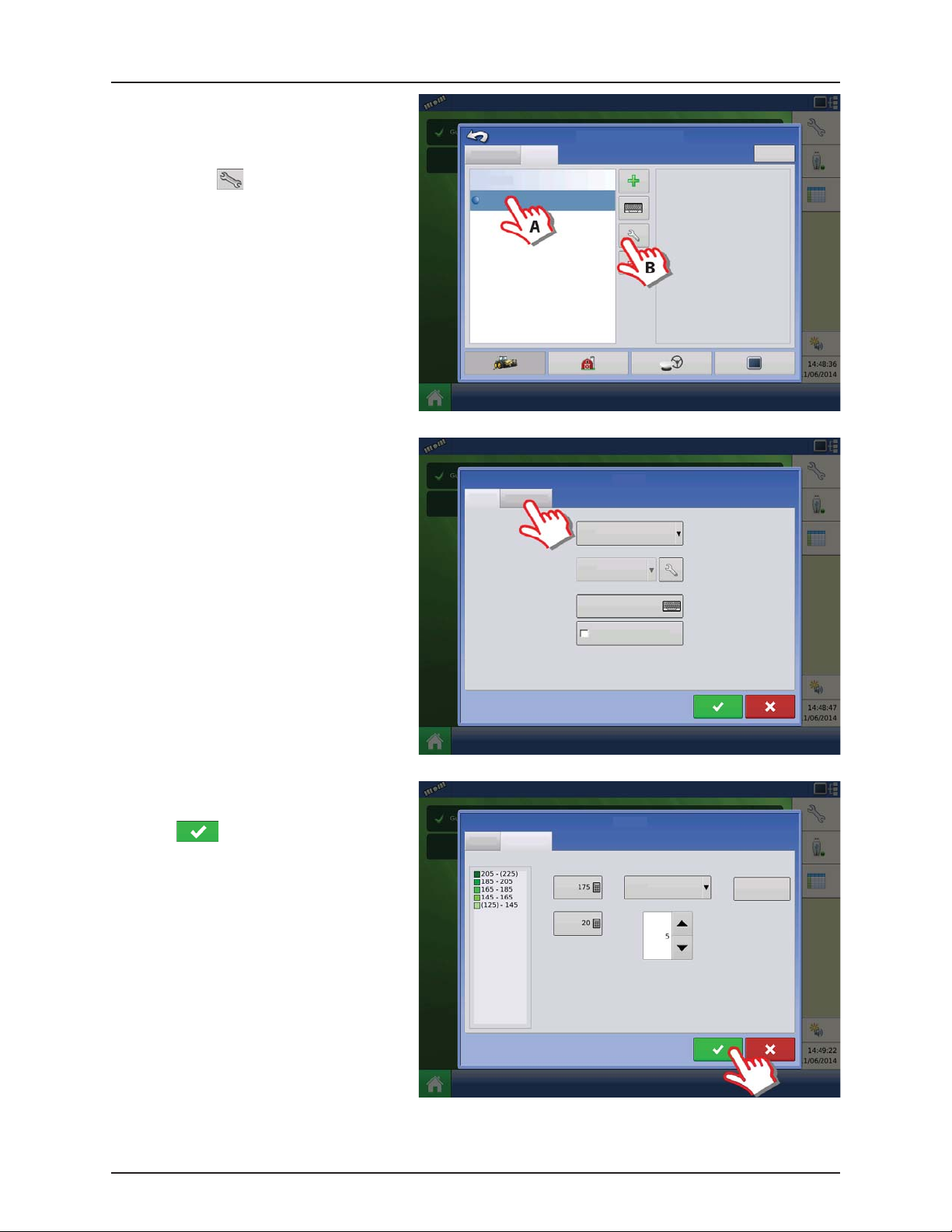
4 - System setup
7. Application Water is now created.
To edit the Legend Settings:
A. Mark the product.
B. Press .
8. Configuration Setup window opens at
“General” tab.
Press “Rate Legend” tab to setup Legends.
Configuration Setup
Configuration Product Equipment
Application
Water
Manufacturer:
Type:
Units:
Restricted Use:
EPA Number:
Carrier
ounces (fluid)
No
Wate r
General Rate Legend
Produc t Units
ounces (fluid)
Manufacturer
None
EPA Number
9. The Legend Settings can be edited as
necessary.
Press to confirm and continue.
SETUP COMPLETED
General Rate Legend
Attribute: Rate
Average
Range Spacing
Restricted Use Pesticide
Wate r
Color Scheme
Single Hue Greens
Ranges
Reset to Default
Legend
ATTENTION! When the complete Quick
Setup Guide has been completed, the controller is ready for use in the field. Refer to “Setup Event” on page 5.5 for
instructions on how to begin a field operation.
4.48
Page 75
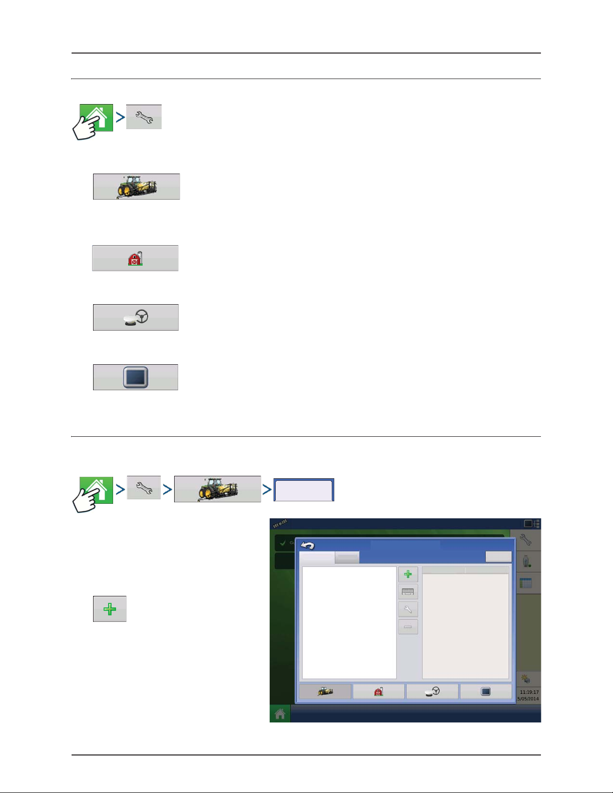
4 - System setup
Configuration
Setup buttons
The Setup buttons shown at the bottom of the Setup screens, are where you can toggle between screens that adjust
settings for Configuration, Management, GPS and display.
• Configuration button.
Press to adjust the configuration settings particular to your vehicle and equipment; as well as enter and edit
product information. For more information, see “Product tab” on page 4.50, as well as “Configuration Setup
Screen” on page 5.1.
• Management button.
Press to access and edit Grower, Farm, Field and Operator information. For more information, see “Management
button” on page 4.51.
• GPS button.
Press to adjust Guidance settings, GPS settings, and lightbar settings (if applicable). For more information, see
“General info” on page 6.1.
• Display button.
Press to adjust settings for Time and Date, brightness and volume settings, operating units, language, enable
video, view features, and also create and restore backups.
Configuration button
Configuration tab
The Configuration tab is where you can create,
view and change configuration settings.
An operating configuration is a task-specific
association of vehicle, implement, controller, and
speed source that is saved for use over different
seasons and on different displays.
• Add button.
Configuration
Configuration
Product
Configuration Setup
Equipment
Equipment
Name
Press to add an operating configuration. A
wizard takes you through the process of
creating a configuration.
• When finished, the new configuration
appears in the list on the left side of the
screen.
4.49
Page 76

4 - System setup
• When you highlight the configuration, the equipment in the configuration are listed in the box on the right side of the
screen.
• Information regarding configurations for specific operations is given in each operations chapter.
• Rename button.
Press to rename the configuration.
• Setup button.
Press to adjust configuration settings.
• Remove button.
Press to remove a configuration.
WARNING! When you remove a configuration all data logged with that configuration will also be removed! However,
±
all log files will remain in memory until exported to the USB drive.
Equipment
• button.
Press to add, edit, or remove information for a specific vehicle, implement or controller.
Product tab
Product
The Product tab is where you can add, edit or
remove product information.
The Product tab is where you can perform the
following tasks:
• Add or import Planting products.
• Add or import Application products.
• Add Application Product mixes (such as a
Configuration Product Equipment
Application
28% UAN
30% UAN
Ag Lime
Configuration Setup
Manufacturer:
Type:
Units:
Restricted Use:
EPA Number
tank mix, or a dry blend of multiple products).
• Add or import Harvest products.
Add button.
Press to add or import a Product. At the
following screen, choose a Product Option:
Add Product, Import Product, or Add Product
Mix (if in Application). From here, an onscreen wizard continues you through each step of the setup process.
• When finished, the new product appears in Product Tab.
• When you highlight the product, information about the product appears on the right side of the screen.
• Specific planting and application product information can be viewed in those respective chapters.
Ferti lizer
gallons
No
4.50
Page 77

4 - System setup
Rename button.
Press to rename the product.
Remove button
Press to remove a product.
NOTE! When you remove a product all regions using that product will also be removed!
÷
Application Settings
Edit Info button Press to edit the following information for the highlighted product in the Product List.
• Product Units
• Manufacturer
• EPA Number
• Check box for restricted use pesticides
Edit Legend button
For more information, see “Legend Settings” on page 5.1.
Management button
The Management tabs, which are accessible from the Management button on the Setup screen, include Grower/Farm/Field,
Season, and Operator.
Grower/Farm/Field tab
Grower
The Grower refers to the business or person that the system is in operation for. Contact information can also be entered for
each Grower. The Grower information will be passed into mapping software for automatic Grower setup within desktop
software.
Press to change the legend settings listed below.
• Average
• Range Spacing
• Color Scheme
• Ranges
• Reset to Default Legend
Grower/Farm/Field
Add button. Press to add a Grower.
Rename button. Edit an existing name of a Grower by highlighting that name and pressing button.
4.51
Page 78

4 - System setup
Setup button. Press to enter information for the Grower’s Name, Tax ID and Memo.
Remove button. Press to remove a Grower.
NOTE! Personal Information entered at this screen can be added or edited at any time.
÷
Farm and Field
In the display, farms are subdivided into fields. You
can associate Field names with a particular Grower.
If the display will be used for multiple Growers,
enter each Grower business name and associate
the field names with the correct grower when the
fields are set up within the system.
In the Field Tab, select a Grower underneath the
drop-down menu at the top. Each farm of that
particular grower is shown in a list, with the fields
within that farm as sub components within that
list.
Grower/Farm/field Season Operator
Grower: Gene Eilers
Farm : Shel don
Field : Low 80
Grower: Seth
Management Setup
Businesses
Boundary
80 acTrue A rea:
Clear
• Add button
79.92 ac
Press to add a Field.
• Rename button
Edit an existing name of a Field by highlighting that name and pressing button.
• Setup button
Edit the Farm and Field information by highlighting that name and pressing button. The Field Information screen
appears.
• Remove button
Press to remove a Field.
4.52
Page 79

The Field Information screen opens, showing the
name of that field in the “Field” title bar.
Field Name information that can be added or
edited by pressing
Possible to edit:
• County
Field Low 80
Area
County
Town sh ip
• Tow ns hi p
• Range
• Section Number
Range
Section
• Legal Description
• Area
Shown in the total acres (hectares) of the
field.
• FSA Number
Refers to the U.S. Farm Service Agency’s four-digit number assigned to every field.
• FSA Area
Refers to tillable acres as established by the FSA.
• Clear Bounds button
Press to center the map on the current GPS position.
Field Information
Farm She ldon
Clear
Bounds
FSA Number
FSA Area
Legal De scription
4 - System setup
79.92 ac
NOTE! The Clear Bounds feature is particularly useful if you have flyer points or have logged a point outside the
÷
mappable range of your current location.
4.53
Page 80

4 - System setup
Importing and Exporting Field Boundaries
Boundaries can be created with the display or imported from desktop GIS software. Any boundary files present in the display
can also be exported for use in desktop mapping software.
NOTE! For more information on creating boundaries, see “Create Boundary” on page 5.3.
÷
• USB Import button
To import a boundary from the USB drive, first go to the Setup Field tab, highlight the correct field in the Farm/Field
list and press the USB Import button.
The File Selection screen appears. Highlight the
desired file to import.
Operator can import/export all fields and
boundaries at once with an .AGSETUP file. For
more information on .AGSETUP files see
“.AGSETUP” on page 8.2.
Grower/Farm/field Season Users
Grower: Gene Eilers
Farm : Sh eldo n
Field : Low 80
Field: High 90
Management Setup
Businesses
Boundary
80 acTrue A rea:
Clear
79.92 ac
Press to complete the import process.
Name
Boundaries
New Folder 1
Field _1.iby
Field _2.iby
Field _3.iby
Field _4.iby
irx_multi_product
Irx_single_product
File Selection
Field:
Farm :
Grower:
Allegon County
Michigan Test Fields
226.13 ac
• USB Export button
To export a boundary to the USB drive, highlight the correct field in the Farm/Field list and press the USB Export button.
At the File Selection screen, highlight the desired field to export.
A screen will appear telling you that the boundary was exported successfully. Press return to the field setup
screen.
Demo
4.54
Page 81
4 - System setup
Season tab
Season
A season is defined as the calendar year that the crop will be harvested. A season has a start and an end date. Creating a
season and setting it to active is required prior to the system logging any data.
The seasons are displayed in lists, with the Active season displayed in bold face type. All new data is logged to the active
season; therefore a season must be set as Active before you can log any new data to it.
• Add button.
Press to add a Season.
• Edit button.
Edit an existing name of a Season by highlighting that name and pressing button.
• Set Active button.
Press to set the season selected in the Summary list box to the active season.
• Season Reminder button.
Press to set the date that the system will prompt the operator to create a new season.
• Remove button.
Press to remove a season.
Operator
Users
Management Setup screen - User tab allows user to add, modify, or delete users from the display.
Add a user
Users
1. Enter first name and/or last name (have to enter a first or last name, recommend entering both)
2. Enter applicator license (optional). Press to continue.
3. Select Operator or Manager (can select either, none, or both). For more information on selecting Operator/Manager
and setting up permissions, see “Permissions” on page 4.57. Press to continue.
4. Enter and verify password (optional)
• Locks the displays ability to load/change operating configurations, access setup and USB, if Manager has a
password set.
• Leaves display unsecure unless each manger sets a password.
• Warning message appears if passwords do not match.
• No restriction for password format (can be any combination of letters, numbers, and special characters).
• Case sensitive.
5. 5. Press to accept.
4.55
Page 82

4 - System setup
Select Specific
User
Edit User
• Setup button.
Press to edit operator information by highlighting that name and pressing button. Setup button allows user to edit
information originally entered when profile was added. Edit button also allows access to more phone, email, and
address information.
• Remove button.
Press to remove an operator.
User Setup button (Edit User)
Users
General tab
• First and Last Name
• Set and Clear Password
• Applicator License
• Memo
Phone/Email tab
• Home Phone
• Mobile Phone
• Business Phone
• Home Email
• Business Email
General Phone/Email Address Permissions
First
Last
Applicator License
Memo
Passw ord
George
Eilers
Edit User
Set Password Clea r Password
Address tab
• Address
• Extended Address
• City/Locality
• State/Province
• Country
• Postal Code
4.56
Page 83

4 - System setup
Edit Person
Permissions
This is an optional function that defines what access the user will have in the display. Users are defined as Operator or
Manager (can select either, none, or both).
Operators
• Have full or limited access
• No access to USB or Setup options, unless
also set as a Manager
Can import from USB from Map Screen (RX,
patterns, boundaries)
• Manager sets up privileges
Managers
• Full access to the display settings and
functions
• Only user that can change the selected
configuration
• Ability to log out of the display
System can be set up with operators only.
Passwords are not used when set up this way.
General Phone/Email Address Permissions
User Role
Operator
Manager
Edit User
Permission Level
Full
Full permission provides this user access to all
unlocked features and functionality.
Permission Level for Operators
Full Permission
Provides full access to features and functionality on the map and home screen. A user, set only as an Operator, cannot select
a different configuration and cannot access USB or Setup, when a manager is setup in the display.
Basic Permission
No access to:
• Summary screen
• Legend Tab on Map screen
• Marks Tab on Map screen
• Boundary Tab on Map screen
Limits Guidance options to:
• Creating & loading Straight AB or SmartPath patterns
• Nudge
• Remark A
• Save or reset guidance line
4.57
Page 84

4 - System setup
Custom Permission
Can allow or deny the following options:
• Management screen
• Pan/Zoom controls
• Legend Toolbox
• Marks Toolbox
• Boundary Toolbox
• Guidance Toolbox
• Minimize Toolbox
• Each individual guidance pattern
• Ability to remove guidance patterns
Edit User
Edit User
General Phone/Email Address Permissions
User Role
Operator
Manager
Permissions Level
Custom
Management
Field Management
View Summary
Mapping
Pan/Zoom Controls
Legend Toolbox
Boundary Toolbox
Guidance Toolbox
Minimize Toolboxes
Patterns
Straight AB
SmartPath
Pivot
Adaptive Curve
Identical Curve
A+ Heading
Traml ines
Nudge
Shift
Remove Patterns
Management
Field Management
View Summary
Management
Field Management
View Summary
Display uses Traditional mode when Field Management is checked. Events using the Traditional
mode are tied to the Grower/Farm/Field structure.
Display uses Events Only mode when Field management is unchecked.
Management, GPS/Guidance, Console Setup, and External Storage Buttons are locked for Operators.
A User can be setup as an Operator and Manager to have the same access as a Manager.
USB buttons are locked for Operators if a Manager is present in the system. A Manager can access
USB menu by pressing button and inputting their password.
Setup buttons are locked for Operators if a Manager is present in the system. A Manager can access
setup menu by pressing button and inputting their password.
A User can be setup as an Operator and Manager to have the same access as a Manager.
4.58
Page 85

4 - System setup
The Home and Map screen will appear different depending on how you assigned user permissions. For setting up users with
permissions see “User Setup button (Edit User)” on page 4.56.
Basic Permissions - Home screen
• No Summary screen.
• Setup and USB buttons are locked (as indicated by a padlock icon on those buttons).
• Brightness and volume are on home screen - settings saved per operator.
• Operator Change - Option to continue or start new operation when operators change.
Full Permissions - Home Screen
• Summary screen button is present.
• Setup and USB are locked.
• Management, GPS/Guidance, Console Setup, and External Storage Buttons are locked for Operators.
• A manager can access these buttons by pressing the button and inputting their password.
A user, set only as an Operator, cannot select a different configuration, when a manager is setup in the display. When a
manager is setup in the display, only a managers can unlock and change the configuration so the manager should make
sure to select a configuration upon setup.
Map screen appearance of an operator with Basic
permission. Only the Guidance toolbox is present.
Operator can
• Create guidance lines
• Straight AB
• SmartPath
• Nudge
• Guidance setup
Guidance
New
Patte rn
Load
Patter n
Manage
Patte rns
Accessing Setup Menus
1. Press button.
2. Select Manager from drop-down menu. Press .
3. Enter password. Press .
Now have complete access to the setup menus:
• Configurations Settings
• Grower management
• GPS settings
• Display settings
Do not have to be a Manager to create certain objects:
• Grower
• Far m
• Field
• Product (can't change units)
1
4.59
Page 86

4 - System setup
Accessing USB
1. Press button.
2. Select Manager from drop-down menu. Press .
3. Enter password. Press .
Now have complete access to the USB functions:
• Import/export
• AgSetup files
• Export data
• Upgrade firmware
• Advanced options
Advanced Options with USB
• Ability to create/restore backups from USB
• Options for exporting log files
• Export by grower
• Export data at shutdown
• Export all log files
Forgotten Passwords
When a Manager forgets his password he won't be able to access Setup.
Tech Support will be able to generate a password based on the serial number and firmware of the monitor.
Password generator will require the following
information:
A. Display serial number
B. Major revision
• First digit of firmware version
C. Minor revision
• First digit of firmware version after
CAN A
DISPLAY
CAN B
Devices
Firmw are:
Firmw are ID:
Hardware ID:
Produc t ID:
Serial Number:
Revision:
Run Time:
Boot Counter:
decimal.
Example
A. Version 5.4
B. Major = 5
C. Minor = 4
Diagnostics
Only needed when a Manager forgets their
password and works within the display until
firmware is upgraded.
How will Tech Support identify if the person calling in is a Manager or not?
They will ask the caller, “Are you a Manager in the display?” If the customer answers yes, Tech Support will generate the
password. If the customer answers no, Tech Support will require a Manager to authorize the display to be unlocked.
What if a customer doesn’t want to risk forgetting passwords and generating new ones?
A display does not need to be locked with a password. The display can be operated as it has been in the past without
passwords. Operators can also be setup with limited or customized access without passwords.
Tips
• Managers, keep a record of all passwords set in the display.
• Operators, write down your personal password.
4.60
Page 87

4 - System setup
• To avoid Operators obtaining unwanted access to a display, instruct them to call a Manager for help with passwords
before Tech Support.
Businesses Tab
Businesses
The businesses are displayed in lists, with the Active business displayed in bold face type. All new data is logged to the active
business; therefore a business must be set as Active before you can log any new data to it.
• Add button.
Press to add a business
• Edit button.
Edit an existing business by highlighting that name and pressing button.
• Remove button.
Press to remove a business.
4.61
Page 88

4 - System setup
Display Button
The Display screen contains the following tabs:
• General tab
Displays settings related to Time, Date, display screen settings, operating units, video and display owner information.
• Owner tab
Contains functionality for setting up a Display Owner and making any needed edits to the owner personal information.
• Features tab
Lists unlocks for a particular display.
• Advanced tab
Includes information related to log files and system backups.
General tab
General
The Setup General Tab is consists of the following
items:
• Time/Date button
Press button and use / to
adjust the hours, minutes, A.M./P.M. settings,
month, date and year. To make these
changes effective, press .
NOTE! The display will then shut down
÷
immediately. If you do not want to shut the
General Display Features
Brightness
Volume
Time / Date
Time Zone
Americas (Central Time)
Console Setup
Advanced
Language / Country
Auto
English / US
Operating Units
Imperial
Calibrate
Tou ch sc re en
ISOBUS Settings
Enable Video
display down, press the Close (Red X)
button; however the time/date changes
will not be accepted until the display is shut
down and restarted.
• Brightness and volume percentages.
To change these, press the Brightness/Volume button and use / to change the percentage of the
Display Brightness and Speaker Volume.
NOTE! Pressing the Automatic box will display the Display Brightness - Trim setting, which makes adjustments to the
÷
display’s brightness according to the available or ambient light.
• Calibrate Touchscreen.
Press this to launch the Touch screen Calibration wizard. Calibrate the touch screen by following the on-screen
instructions.
WARNING! Do not use any sharp objects to operate the touch screen or the display may be damaged.
±
• Time Zone
Use the drop-down menu to select your time zone.
4.62
Page 89
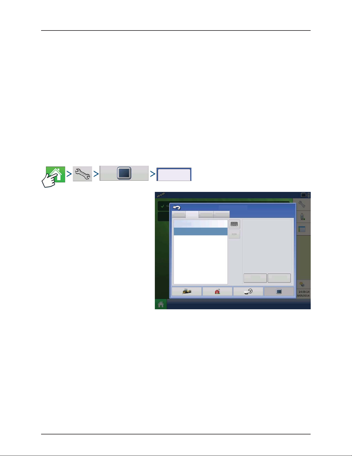
4 - System setup
• Language/Country Selection
Use the drop-down menu to select the language.
NOTE! The HC 8500/9500 display decides the language in the Virtual Terminal (JobCom). If the selected language in
÷
the HC 8500/9500 display is not available in the sprayers JobCom, the language in the VT/JobCom will remain English
or the language linked to selected display language.
It is not possible to select specific language for the VT/JobCom when used in HC 8500/9500.
• Operating Units
Select either Imperial or Metric.
• Enable Video
Enables input from up to four video cameras.
• ISOBUS Settings
Enables Virtual Terminal and Task Controller. See “ISOBUS Settings” on page 4.67 for explanation of settings.
Display tab
Display
The Display tab contains functionality for setting
up a Display Owner and making any needed edits
to the owner personal information. The Display
Owner information is used in the product
application report feature of application rate
control.
• Nickname
• Serial Number
• Product Type
• Owner
• Phone
• Email
• Address
• Image
• Change Owner
• Edit Information
General Display Features
This Display
geo
Phone:
Consol e Setup
Advanced
Nickname: geo
Serial Number: 2009120056
Produc t Type: AL I NTEGRA
Owner: George Eilers
Phone:
Email:
Address:
Image:
Change
Owner
Edit
Information
4.63
Page 90
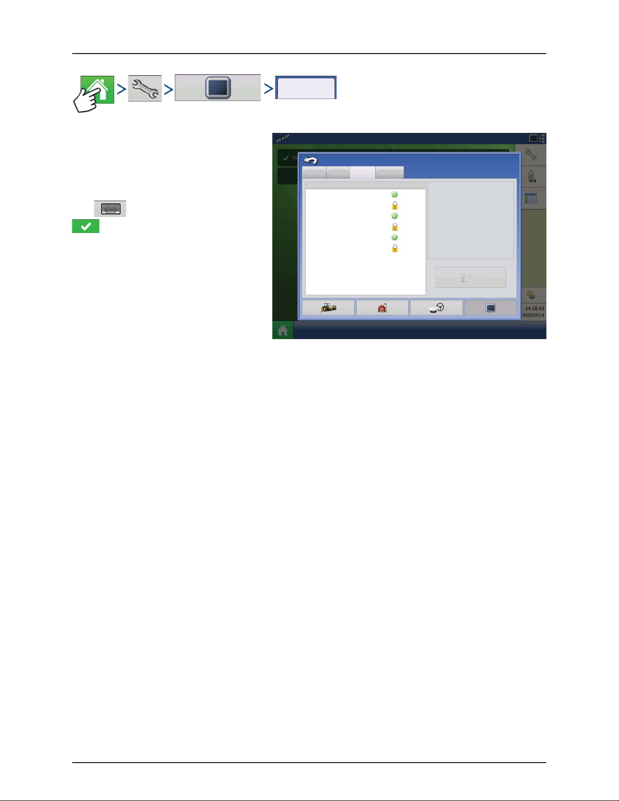
4 - System setup
Features tab
Unlocking Features
The Features Tab is where you can enter unlock
codes. Unlock codes are unique to the serial
number of each display and the feature
registration number. You must supply these
numbers to your dealer when purchasing any
unlock codes.
Press to enter the unlock code and press
to enable the feature.
NOTE! Once a feature is unlocked, that
÷
feature remains with that display and
cannot be transferred to another.
ATTENTION! Features used with HARDI®
sprayers are always enabled.
Featu res
General Display Features
Feature: Status
Automatic Swath Control
Multiple Product
Norac UC5 Interface
Fan Frame - Feed Gate Control
ISOBUS
Intellislope Tilling
Advanced
Consol e Setup
Enabled
Off
Enabled
Off
Enabled
Off
Feature D escriptio n:
Unlock
4.64
Page 91
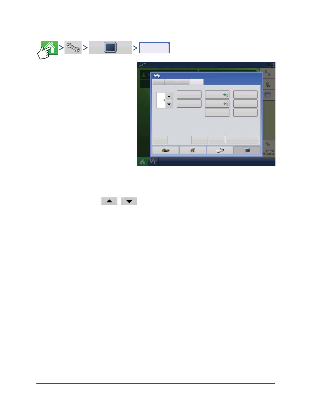
Advanced tab
The tab allows to specify:
• Settings for copying log files.
• Specify Key Switch Standby settings.
• View and manually upgrade module
firmware.
• Create and restore backup files.
WARNING! The Export Diagnostic Files,
±
Advanced Parameters, Copy Debug Files,
Clear Debug Files and Service Mode
functionality on the Advanced Tab is
reserved for use by the manufacturer. DO
NOT change any of these settings without
specific instruction from the manufacturer.
Advanced
General Display Features
Key Switch Standby
(minutes)
About
Log Files
Export Error
Diagnostic Files
Export GPS
Diagnostic Files
Consol e Setup
Advanced
Memory Guidance
Create
Backup
Restore
Backup
Clear Internal
View Module
Firmw are
4 - System setup
Copy
Debug Files
Clear
Debug Files
Memory
Test
Remove
Patte rns
Service
Mode
Memory
Advanced
Param eters
Key Switch Standby This setting allows the display to remain powered up after the vehicle power has been shut
down. Instead, the display will switch into standby mode and will appear to be shut off;
however the power light will change to an amber color. Pressing the touchscreen while it is in
standby mode will immediately turn the screen back on again.
Use / to specify a length of time that you wish the display to remain powered
up in standby mode after the vehicle power has been shut down.
NOTE! When the time you specified in Key Switch Standby is nearly expired, then the
÷
amber-colored power light will flash on and off immediately preceding shutdown. If
you wish the display to remain powered up for a longer period of time, touch the
display to restart the Key Switch Standby countdown.
About button Displays product licensing information and copyright information.
Log Files These settings allow you to copy your data in the display.
• Export by Grower.
Press of export log files by growers.
• Export Data Files.
Press to copy all logged data in the display to the USB drive.
• Export Data Files on Shutdown.
Checking this check box will copy all log files to the USB drive when the display is
powering down.
See “Export Files” on page 4.108 for more information.
4.65
Page 92

4 - System setup
Memory Adjusts information stored in the display’s internal memory.
• Create Backup.
Press to create a backup file of all configuration settings, products, and Grower-FarmField Management data structure on the USB drive. Backup files are stored using the .ibk2
file format.
• Restore Backup.
Press to restore a backup file from the external data drive to the internal memory of the
display.
• Clear Internal Memory.
Press this button to clear the internal memory of the display. The system will present a
warning dialogue box and ask if you would like to create a backup file prior to clearing
the memory.
WARNING! Once you clear the system’s internal memory, this information is deleted and
±
cannot be restored unless a backup has been made.
View Module Firmware Displays the Module Firmware Management screen, which is a list of all firmware modules and
firmware versions that are available for the display.
NOTE! The Module Firmware Management list includes module firmware that you may
÷
not be running.
• Import
Imports any firmware stored on the USB drive into the display memory.
• Direct Upgrade
Upgrades an individual module directly from the USB.
• Remove
Removes unwanted module firmware from the Module Firmware Management list.
NOTE! Pressing the Remove button does not remove firmware from the module itself. It
÷
merely removes the upgrade file from the display.
Remove Patterns Pressing this button permanently erases all guidance patterns from the display’s memory.
4.66
Page 93

4 - System setup
Virtual Terminal
Virtual Terminal together with HC 8500/HC 9500
The following has to be set up in both the HC 8500/HC 9500 software and into the VT-software:
• Boom width (VT menu 3.3.1).
• Number of sections (VT menu 3.3.2).
• Number of nozzles per section (VT menu 3.3.3).
General info about Virtual Terminal
The display is compatible with the ISO 11783 (ISOBUS) Virtual Terminal Standard. This enables support of many ISOBUS
compliant implements on the display. Virtual Terminal functionality enables the compliant implement’s user interface to be
viewed and controlled on the display.
Common Terminology
ISOBUS Working Set One or more ISOBUS modules that control an implement’s functionality.
Working Set Master (WSM) Main module responsible for coordinating all communication between the VT and the
Working Set including loading of the Object Pool to the VT screen.
Object Pool Defines graphical components that ISOBUS modules present on a compatible display.
WARNING! Before operating an ISOBUS implement with the display, read the operator’s manual provided by the
±
implement’s manufacturer, e.g. HARDI® and follow all safety information provided in the manual. When this display is
used with an ISOBUS implement, the information and functions on the display are provided by the implement ECU
and are the responsibility of the implement manufacturer.
To enable the Virtual Terminal:
ISOBUS Settings
ISOBUS Settings
Virtual Terminal Task Controller
Enable Virtual Terminal
Broadcast GPS Speed
Auxiliary Module Support
Use 480 Mask Size
Funct ion Ins tance
Enable Virtual Terminal
ISOBUS Settings
Enable Task Controller
Func tion I nsta nce
4.67
Page 94
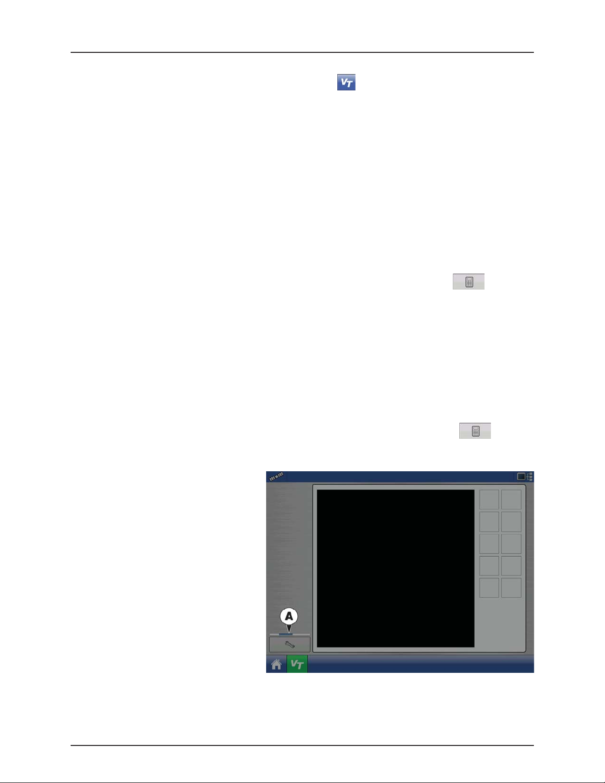
4 - System setup
Enable Virtual Terminal Assign Virtual Terminal functions to ISO compatible inputs.
Once a Virtual Terminal has been enabled will appear in the task bar. Toggle between the
Virtual Terminal run screen and other display functions by pressing the VT button.
NOTE! Always enable this when connected to a HARDI® ISOBUS system.
÷
Broadcast GPS Speed
Auxiliary Module Support Allows non-HARDI® Auxiliary Module to be used as an ISO device.
Use 480 Mask Size Not used for normally setup HARDI® sprayers.
Virtual Terminal Functional
Instance
Enable Task Controller Checking this box allows the HC 8500/HC 9500 to communicate with the sprayer’s JobCom
Task Controller Function
Instance
Checking this box allows the implement to use GPS ground speed that has been gathered by
the display.
Do not check this when using the sprayer speed sensor - see also “Speed Input Settings” on
page 4.70.
Not used for normally setup HARDI® sprayers.
Always set to 0 except when there are multiple VT’s on the ISO Bus. Use to change
instance. Reboot Display.
computer and thereby use its functions, e.g. Automatic Swath Control.
If having more than one screen, Automatic Swath Control can only run on one of these
screens. This screen is selected by setting the Task Controller Function Instance value.
NOTE! Always enable this when connected to a HARDI® ISOBUS system. Otherwise it will
÷
give an error message when starting a spray job in the working screen on the HC
8500/9500.
Always set to 0 except when there are multiple screens on the ISOBUS. Use to change
instance. Reboot Display.
When an ISOBUS compliant implement is
connected to the display for the first time, the
implement WSM sends its graphic interface, called
the Object Pool, to the display.
Status bar (A) appears while Object Pools are being
loaded. This process might take several minutes
depending on the number of Object Pools being
loaded.
Once loaded, object pools are stored in the display
memory.
4.68
Page 95
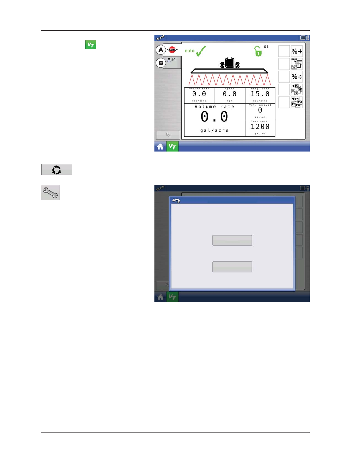
If there are multiple ISO implements connected,
press the VT button to toggle between
Working Sets.
The Working Sets can also be accessed by pressing
tabs (A) or (B) individually.
ATTENTION! If the HARDI® VT displays the
default 4 boom section (4 red lines below
the boom), then there is no communication
with the JobCom. Make sure to power On
the JobCom on at the SetBox before
proceeding.
Advance through multiple screens of soft keys. This button remains hidden unless more than 10 soft keys
are present.
Opens the Virtual Terminal Settings
screen.
4 - System setup
Virtual Terminal Settings
• Auxiliary
Assign implement functions to ISO
compatible inputs.
• Clear Virtual Terminal
Allows operator to clear the Object Pools
Auxiliary
Assignment
sent to the display from the implement WSM.
After the object pools have been cleared, the
next time the implement is connected the
object pools will be transferred from the
Clear Virtual
Term in al
implements WSM to the display again. When
this button is pressed, a warning dialogue
box appears with the following message:
“Are you sure you want to clear the saved
interface files from all virtual terminal devices
Each device will resend its interface the next
time it is connected.”
ATTENTION! No data will be lost while clearing the Virtual Terminal. All data will be reloaded to the display next time
the HARDI® JobCom is connected.
4.69
Page 96

4 - System setup
Your Specific
Configuration
Speed Input
Settings
Speed Input Settings
Configuration
This will show sprayer speed in the upper blue bar of the working screen, when spraying.
ATTENTION!
• The Virtual Terminal has to be setup to “Tractor Alpha speed” or “Radar speed” (Menu 3.1).
• The Display has to be setup to “Broadcast GPS Speed” in the Console Setup ISOBUS Settings menu.
Choices for Primary Source include:
• Hardi
• Display GPS
• Auxiliary Device
Speed Input
Primary S ource
Hardi
Other Possible Options (not used for HARDI®
sprayers):
• Manual Speed
Speed
Input
Primary Source selections to use:
Hardi Display GPS Auxiliary Device Manual Speed
Trailer sprayer with
Sa feTra ck /In tel li Trac k
Self-Propelled sprayer Can be used. Can be used. Not used. Not used.
SARITOR sprayer Not used. Always select “Display GPS” as
Lift mounted sprayer Not used. Can be used. Can use speed input from the
*Choices for Auxiliary Device Channel include:
• Wheels
• Radar
If you are using a backup radar speed source it is recommended that you calibrate it before the season begins.
• Filtered
This setting is used only as a backup speed source for low pulse ground speed sensors.
ATTENTION! When “Hardi” option is selected as Primary Source, you may use the VT speed calibration (menu 3.1).
NOTE! If “Display GPS” is selected, the “Hardi” option must be selected as backup source.
÷
Must always use “Hardi” as
speed source as the steering
system cannot use GPS as
speed source.
Not used. Not used. Not used.
Not used. Not used.
speed source.
Not used.
tractor*
4.70
Page 97

Automatic Swath Control (AutoSectionControl)
Your Spec ific
Configuration
Automatic Swath Control
The Automatic Swath Control feature turns
sections off and on automatically based upon the
following conditions:
• Entering and exiting internal and outer field
boundaries.
• Entering and exiting previously-applied areas
within a field.
At the Configuration Setup screen, press the
Automatic Swath Control button. At the screen
that appears, options are:
• Outside Boundary Option
Select one of the two options to determine
system behavior when a section exits a field
boundary.
• Coverage Option
In the Coverage Option area, you must
choose between three options:
• Minimize Skip
Turns off the implement section after the entire section is fully inside your coverage area.
This prevents the possibility of skips.
• Minimize Overlap
Turns off the implement section when that section first enters your coverage area.
This prevents the possibility of overlaps.
• User Defined
Allows you to choose what percentage of the implement section is within the coverage area before that section
turns off. For example, if you choose 50%, then the section will switch off when half of it is within your coverage
area.
• Turn-On Look Ahead
Determines how far ahead the system looks
to turn the sections back on. This
compensates for delay in the system when
the sprayer sections are turned on.
• Turn-Off Look Ahead
Determines how far ahead the system looks
to turn the sections off. This compensates for
delay in the system when the sections are
turned off.
Configuration
Application
Outside Boundary Option
Keep Unchanged
Turn Sect ion O ff
4 - System setup
Automatic Swath Control
Coverage Option
Minimize Skip
Minimize Overlap
User Defined
Look Ahead Settings
Turn- On:
Turn- Off :
Look-Ahead
Settings
4.71
Page 98

4 - System setup
You r Spe cif ic
Configuration
Vehicle Offsets
Configuration
Vehicle Offsets
When the process of setting up a Vehicle is completed by using step-by-step procedure in “Installation” on page 4.1, you can
later re-configure vehicle offsets.
These offsets define where the machine’s rear axle and hitch is in relation to the GPS antenna. These settings are used by
mapping.
The GPS Offsets settings consist of two tabs: the Antenna Tab and the Hitch Tab.
Antenna Offsets tab
At the Antenna Tab, enter the distance from
locations on the vehicle to the antenna.
• Measure and enter the horizontal distance
from the rear axle to the position of the GPS
antenna.
Select IN FRONT or BEHIND to indicate the
position of the antenna in relation to the rear
axle.
• Measure and enter the horizontal distance
from the center line of the vehicle to the
position of the GPS antenna.
Select LEFT or RIGHT to indicate the position
from the vehicle center line.
• Measure and enter the vertical height of the
antenna above the ground.
Antenna
Hitch
Vehicle Offsets: JD 4630
Enter Distance from Vehicle References to the Antenna
Antenna Location from
Rear Axle
Antenna Location from
Centerline
Antenna Height from
Ground
In Front
Left
NOTE! Accuracy when measuring for a specific setting is essential to ensure proper machine performance.
÷
Hitch Settings tab
The Hitch Tab allows you to enter in the distance
from four different mounting positions on the
tractor to the rear axle.
Press to enter these values in if using the
hitch point.
NOTE! Accuracy when measuring for a
÷
specific setting is essential to ensure proper
Antenna
Hitch
Vehicle Offsets: JD 4630
Enter Distance from Rear Axle to the Following Locations
Rear Drawbar
Rear Lift Arms
Front L ift Ar ms
machine performance.
Mount Tab Settings
The Mount Tab will only be available when using a
Self-Propelled sprayer.
This allows you to enter in the application location
from the rear axle. Press to enter in the
distance and the drop-down box to select if it is in front or behind of the axle.
4.72
Page 99

4 - System setup
Select Your Specific
Configuration
Advanced Swath Offsets
Swath Section Offsets
Configuration
Offsets
The Implement Offsets screen opens. On a typical HARDI® configuration, this screen may consist of up to three tabs:
• Implement tab.
• Liquid with Hardi tab.
• Boom Control tab.
Implement tab
Implement Modelling:
Implement Type:
• Standard
• Hardi SafeTrack
AT TENTION! For IntelliTrack sprayers, select
the “Hardi SafeTrack” option.
Hitch to Axle Distance:
Press to type in value.
Type in the measured value from Hitch of the
sprayer to the axle.
Implement Rear Hitch:
Here is no relevant settings for HARDI®
sprayers.
Implement Liquid with Hardi
Implement Modeling
Implement Rear Hitch
Implement Offsets: Hardi Commander
Boom Control
Implement Type
Standard
Front Hitch to Rear Hitch
Hitch to Axle
Distance
Implement Provides a Rear Hitch
Lateral Offset from Centerline
Heading
Aggressivene ss
Left
Liquid with Hardi tab
Forward/Backward Distance from Hitch:
• Set distance between the hitch eye and the
nozzles.
Left/Right Distance from center line:
Implement L iquid with Hardi Boom Control
Implement Offsets: Hardi Commander
Forward/Backward Distance from Hitch
25 ft Behind
• For asymmetric booms. As HARDI® booms
are never asymmetric, this option must be set
to 0 cm. Left or Right selection does not
matter.
Boom Control tab
Left/Right Distance from Centerline
Left
Forward/Backward Distance from Hitch:
• Set distance between the hitch eye and the nozzles.
Left/Right Distance from center line:
• For a symm etr ic bo oms. As H ARD I® b ooms are neve r as ymme tri c, t his o ptio n mu st be set to 0 c m. L eft or Rig ht s ele ct ion
does not matter.
4.73
Page 100
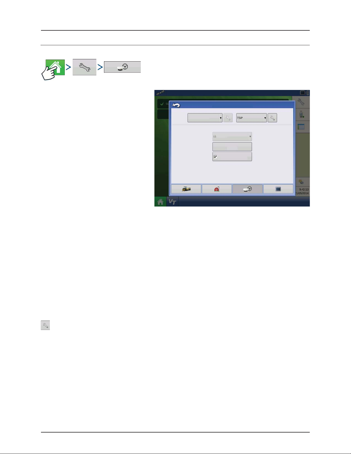
4 - System setup
GPS Guidance/Steering Control
Setup
• Steering
• Manual Guidance
Select this to perform guidance by
lightbar while manually steering the
Steering:
Manual Guidance
vehicle.
• OnTrac2+ (CAN A)/OnTrac2 (CAN B)
Is mounted at the tractor’s steering
wheel.
• ParaDyme/GeoSteer
Can be used with Self-Propelled
sprayers and as optional equipment
for tractors.
• OnTrac3
Is mounted at the tractor’s steering
wheel.
• SteerCommand
Can be used with Self-Propelled sprayers and as optional equipment for tractors.
• Receiver
Set type of GPS interface protocol to Autodetect, Serial, CAN or TSIP.
• Operator Presence Alarm
The Operator Presence Alarm disengages guidance control if the operator does not have any interaction with the
display for a specified period of time. Use the drop down menu to specify the period of time before guidance is
automatically disengaged.
• Lightbar Settings
For more information, see “Lightbar Settings” on page 4.80.
• Required Differential Correction for Guidance
When unchecked allows guidance to operate without differential correction.
Pressing the Setup (wrench) button on the Guidance Tab opens the guidance system settings for the selected
guidance system.
GPS/Guidance Setup
Receiver:
Operator Presence Alarm
Minutes
Lightbar
Settings
Require Differential
Correction for Guidance
NOTE! In order to use guidance with the display, you must have a GPS receiver capable of a GPS output rate of 5 Hz
÷
or more.
4.74
 Loading...