

Page 1
Quick Guide: HARDI Controller HC 5500
679028-103 --- Controller software 5.14 --- Language GB
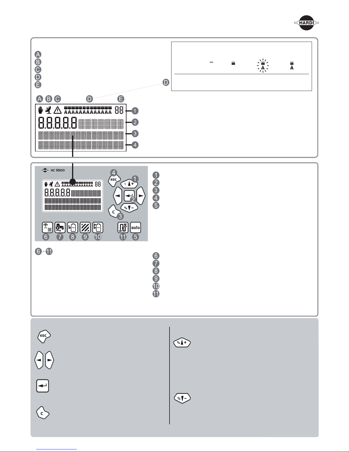
Automatic/Manual mode status
Variable application rate status
Service interval warning
Boom status without dual line
Active register (area trip)
Symbols in display’s 1
st
line
Symbol display and register number
Preset key readout (keys 6-11 below) or menu number
Optional readout
Optional readout
Press the key shortly, and it will show the preset
readout.
Hold the key down for one second, and it will
work as a short cut to a certain menu.
Navigation keys
Enter key
Clear key
Escape key
Automatic control key, which also clears % over / % under rate
Volume rate
Speed
Tank contents
Area
Volume sprayed
Remaining distance
or area
Menu 1.1 :
Menu 3.1.1 :
Menu 1.2 :
Menu 1.3.1 :
Menu 1.3.1 :
Menu 4.1.1 :
Volume rate
Speed calibration
Tank contents
Select register
Select register
Measuring distance
Additional key information
• Escape a menu (hold to escape all menus)
• Escape without changing value
• Move the selection of digits or letters to the
left or to the right
• Enter a menu
• Confirm (accept) a value
• Clear a value
• Reset the active register (hold until
countdown is finished)
• Scroll up
• Increase a value
• Increase volume rate in steps or select
another preset application rate
• Scroll down
• Decrease a value
• Decrease volume rate in steps or select
another preset application rate
D1 D2 D3 D4
Flashing* Spraying
Section: off on off on
Main: off off on on
* Section closed by Auto ON/OFF or external variable rate control.
Page 2
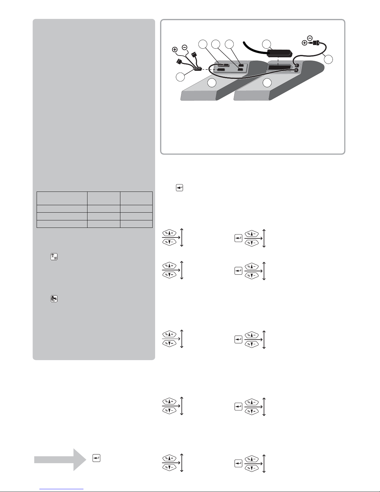
12 V
D E
A B
F
12 V
G
C
H
Menu tree
The first steps to select a menu are shown below.
Press to proceed into the menu.
See the relevant section in the instruction book.
Press ESC and hold to exit the menu system.
5 LOGBOOK
5.1 Print
5.2 Data dump
4.1 Measure
4.2 Service intervals
4.3 Stop watch
4.4 Alarm clock
4.5 Test
4.6 Speed simulation
3.1 Speed
3.2 Flow
3.3 Boom
3.4 Regulation constant
3.5 Tank gauge
2.1 Display readout
2.2 AUTO functions
2.3 VRA/Remote
2.4 Set clock
2.5 Alarms
2.6 Register names
1.1 Volume rate
1.2 Tank contents
1.3 Select register
4 TOOLBOX
3 CALIBRATION
2 SETUP
1 DAILY SETTINGS
Basics to get going
Boom data, spray flow, volume rate and speed
calibration must be entered.
Go to the menu on the Controller and find the
relevant section in the instruction book.
Boom data
[3.3.1 WIDTH]
[3.3.2 NUMBER OF SECTIONS]
[3.3.3 NOZZLES PR. SECTION]
Flowmeter calibration
[3.2.1 FLOW CONSTANT]
The below PPU value is approximate and a
practical calibration is recommended.
The standard values for HARDI flow housing are:
Volume rate
Press and hold until
[1.1 VOLUME RATE] is shown.
Speed calibration
Press and hold until one of the following is
shown:
[3.1.1 Sprayer] Speed sensor on sprayer
[3.1.2 Tractor] Speed sensor on tractor
[3.1.3 Radar] Speed sensor is a radar
The practical calibration is recommended.
One outside
groove
No outside
groove
Orifice (mm) 13.5 20.0
Flow range (liter/minute) 5 to 150 10 to 300
Approx. PPU 120.00 60.00
Connections
A. Controller
B. Spray box
C. Cable from Spraybox
D. COM 1
E. COM 2
F. AUX Cable -12 Volt (optional)
G. Cable from junction box
H. Power - 12 Volt
Main menu
Start screen
 Loading...