

Page 1

Content
Glossary and pictorials symbols ................................................. 2
Operator safety ........................................................................... 3
Description .................................................................................. 3
Fitting the system ........................................................................ 4
Power supply ........................................................................ 6
Scanbox ................................................................................ 7
Display .................................................................................. 7
Transducer colour codes and plug assembly........................ 8
Speed transducer.................................................................. 8
Flow transducer .................................................................... 9
Optional transducers ............................................................10
Start-up ...................................................................................... 11
Reading chosen volume rate ............................................... 11
HM 1500: Changing the desired volume rate for alarm ....... 11
HC 2500: Changing the volume rate.................................... 11
Menus ....................................................................................... 13
General keystroke ................................................................13
Keystroke menu tree chart ...................................................14
Main menu .......................................................................... 15
Display readout ....................................................................16
Tank contents ...................................................................... 17
Calibration ........................................................................... 18
Alarms ..................................................................................23
Sensor test .......................................................................... 25
Area meter .................................................................................26
Mistblowers and HM 1500/HC 2500 ..........................................26
Storage ......................................................................................27
Emergency operation ................................................................ 27
Fault finding .........................................................................27
Technical specifications ............................................................ 29
Chart for recording values......................................................... 30
Extended menu ......................................................................... 30
EC Declaration of Conformity ................................................... 32
Parts.......................................................................................... 33
Controller 2500 &
Monitor 1500 ver. 1.13
Instruction book
673294-GB-2002/09
HARDI INTERNATIONAL A/S is without any obligation in relation to implements purchased before or after such
changes.
HARDI INTERNATIONAL A/S cannot undertake any responsibility for possible omissions or inaccuracies in this
publication, although everything possible has been done to make it complete and correct.
Published and printed by HARDI INTERNATIONAL A/S.
1
Page 2
We congratulate you for choosing a HARDI plant protection product.
The reliability and efficiency of this product depend on your care.
Read and pay attention to this instruction book. It contains information for the efficient use and long life of this quality product.
Glossary and pictorials symbols
HM 1500 HARDI Monitor 1500.
HC 2500 HARDI Controller 2500.
Scanbox Junction box for HM 1500 and HC 2500.
Transducer Device that transforms variations to a signal.
Also called a sensor.
[ x ] or [ y ] Variable figures.
PPU Pulses per unit. For flow calibration.
The unit measure is litre.
UPP Unit per pulse. For speed calibration.
The unit measure is metre.
PPR Pulses per revolution. For revolutions calibration.
BK HARDI manual control unit.
BK/EC HARDI manual control unit (with electric on/off and
pressure regulation).
EC HARDI electric control unit.
EVC, ESC or CB Electric control unit (without main valve).
Description/Notes
Warning
Assembly
Operation/Use
NOTE: Text shown in square brackets or in the rectangular window will
be seen on the display.
E.g. [ MAIN MENU ]
Winter storage
Operational problems
Technical specifications
EC Declaration of Conformity
MAIN MENU
Display readout
2
Page 3

Operator safety
Watch for the WARNING symbol
be alert! Note the following recommended precautions and safe
operating practices.
Read and understand this instruction book before using the equip-
ment. It is equally important that other operators of this equipment
read and understand this book.
Turn electrical power off before connecting and disconnecting the
display and transducers, servicing or using a battery charger.
If an arc welder is used on the equipment or anything connected to
the equipment, disconnect power leads before welding.
Test with clean water prior to filling with chemicals.
Keep children away from the equipment.
Do not use a high pressure cleaner to clean the electronic
components.
Press the keys with the underside of your finger. Avoid using your
fingernail.
If any portion of this instruction book remains unclear after reading
it, contact your HARDI dealer or HARDI service personnel for
further explanation before using the equipment.
. Your safety is involved so
Description
The HARDI Monitor 1500 and HARDI Controller 2500 are for use in
agricultural and horticultural production. HM 1500 is a monitor whereas
HC 2500 permits automatic control of application rate.
Main components are:
• Display
• Scanbox junction box
• Flow transducer
• Speed transducer
The matrix display has two lines permitting two lots of information to be
shown at the same time. Display readout includes dosage applied,
speed, liquid rate per minute, total covered area, total volume sprayed
and 9 trip tellers for area covered and volume sprayed. It is illuminated
internally so readout is possible even for night-time work.
3
Page 4
Functions include correct area with closure of up to 8 spray boom
sections, alarm functions for dosage and minimum tank contents and
possibility for audio/visual alarm.
The transducers utilised are chosen for long service life and good
signal quality. Speed, area switch and revolutions transducer is the
same component. The flow transducer has a diode built into the
housing to aid servicing. As the rotor turns, the diode will flash thereby
indicating it functions.
The system has a non-volatile memory with no battery which simplifies
storage. All parameters in the menus are saved in the display’s
memory and are not lost when the power is disconnected.
The materials and electronics for the components have been developed to last many years under agricultural conditions.
Options include a 4-20 mA transducer (e.g. pressure), revolutions
transducer, area meter transducer and switch box for boom sections
when used with BK or BK/EC control unit (only for HM 1500).
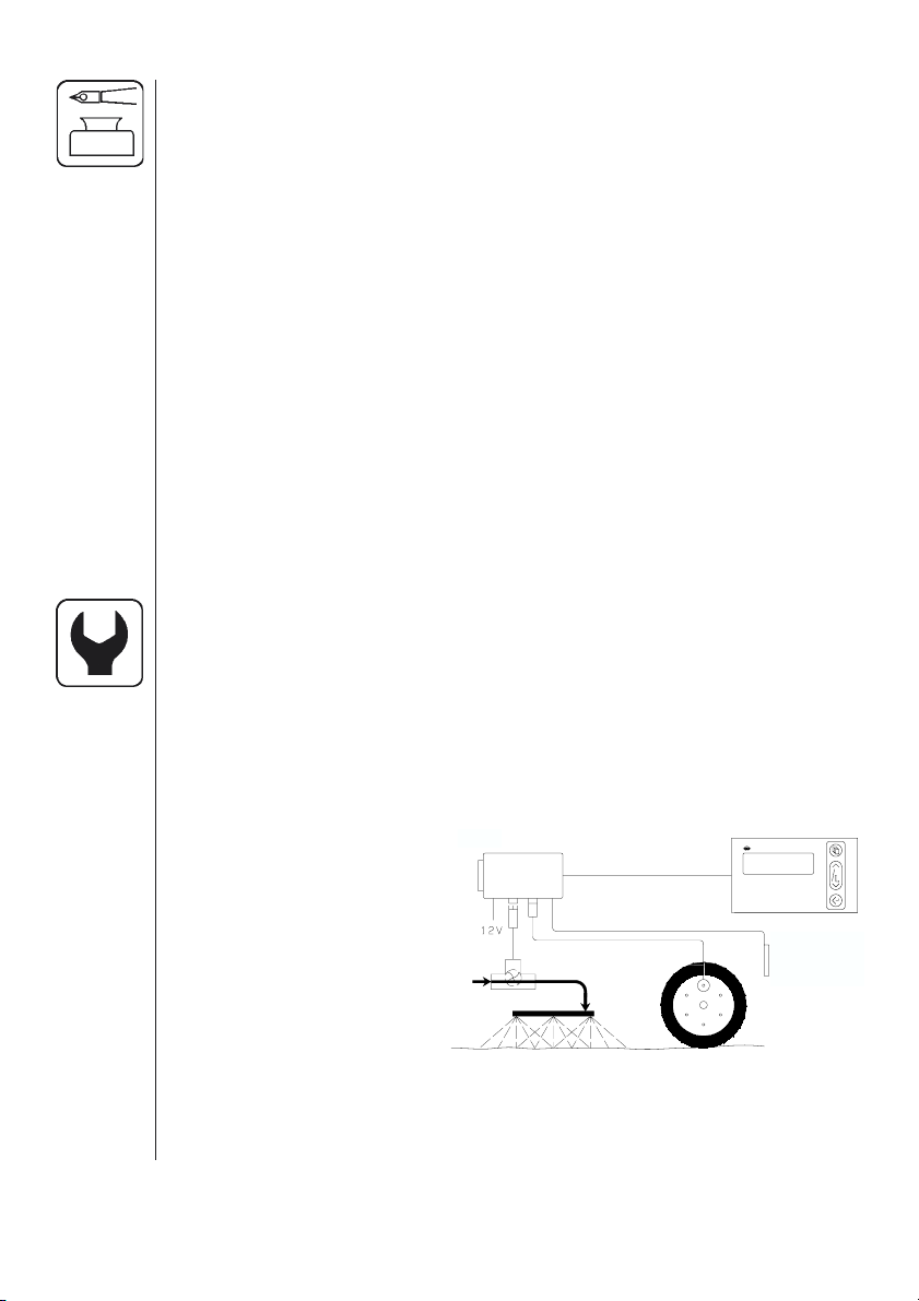
Fitting the system
Please note the configuration and connections for your system.
HM 1500 Monitor with manual control unit (BK, BK/EC)
The active boom width is always the total boom width.
The system can not automatically calculate correctly when one or more
boom sections are turned off.
1. HM 1500 display
2. Display connector cable
4.
3.
2.
1.
3. Scanbox (fuse inside)
4. On/off switch
5. Speed transducer
6. Flow transducer
7.
6.
8.
5.
7. To 12 Volt power supply
8. Switch box connector
cable (not used)
4
Page 5
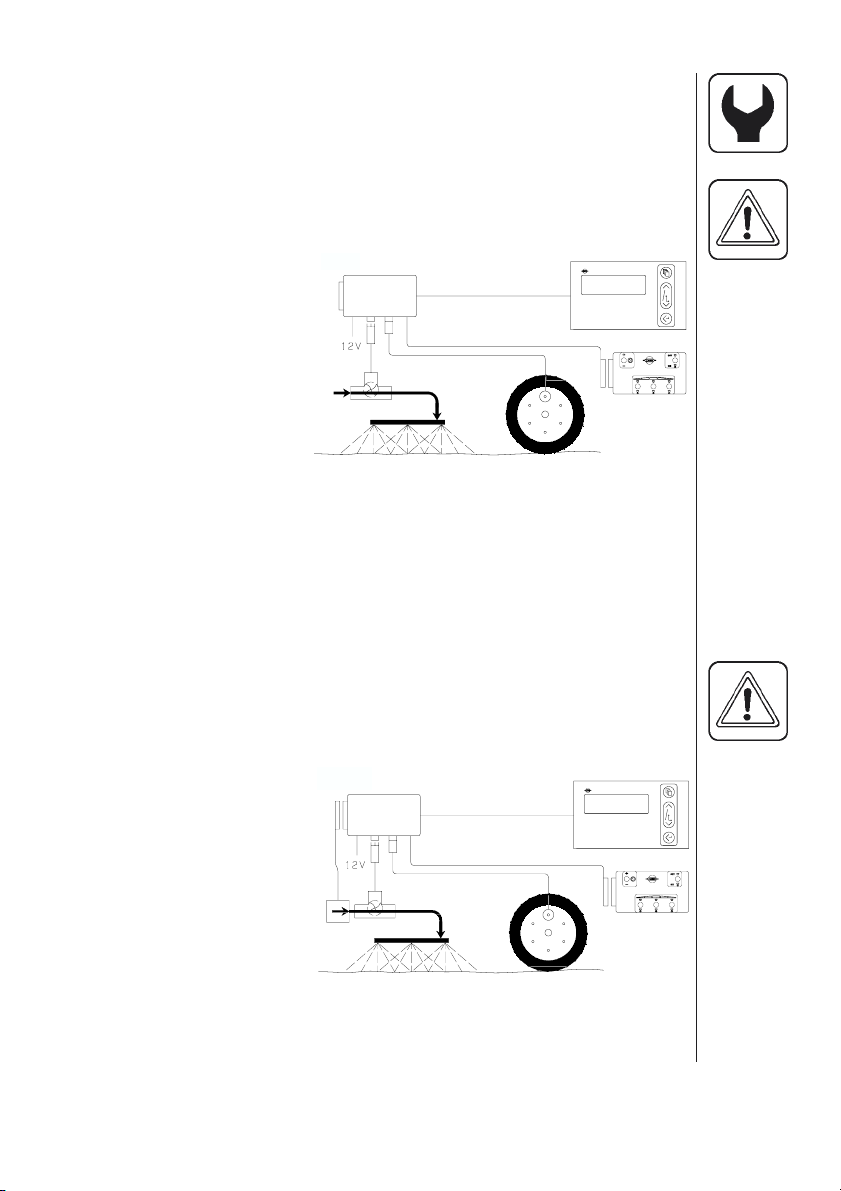
HM 1500 Monitor with manual control unit (BK, BK/EC)
and switch box for boom sections
Active boom width is calculated automatically.
The control box switches are set to correspond with the boom sections.
NOTE: Extended menu setting:
[ Control box ] is [ Connected ].
See “Extended menu”.
1. HM 1500 display
4.
3.
2.
1.
2. Display connector cable
3. Scanbox (fuse inside)
4. On/off switch
5. Speed transducer
6. Flow transducer
7.
6.
8.
5.
9.
7. To 12 Volt power supply
8. Switch box connector
cable
9. Switch (control) box
HM 1500 Monitor with electric control unit
(EC, EVC, ESC, CB)
Active boom width is calculated automatically when the boom sections
are operated.
NOTE: Extended menu setting:
[ Control box ] is [ Connected ].
[ ON/OFF valve ] is [ Not present ] for EVC, ESC and CB.
See “Extended menu”.
1. HM 1500 display
4.
2. Display connector cable
3. Scanbox (fuse inside)
4. On/off switch
5. Speed transducer
11.
7.
6. Flow transducer
7. To 12 Volt power supply
10.
8. Control box connector
cable
9. Control box for electric control unit
10. Electric control unit
11. Connector cable from control unit
3.
6.
2.
1.
8.
5.
9.
5
Page 6
HC 2500 Controller with electric control unit
(EC, EVC, ESC, CB)
Active boom width is calculated automatically when the boom sections
are operated.
NOTE: Extended menu setting:
[ ON/OFF valve ] is [ Not present ] for EVC, ESC and CB.
See “Extended menu”.
1. HC 2500 display
2. Display connector cable
3. Scanbox (fuse inside)
4. On/off switch
5. Speed transducer
11.
4.
7.
3.
6.
2.
1.
8.
5.
6. Flow transducer
7. To 12 Volt power supply
10.
8. Control box connector
cable
9. Control box for electric control unit
10. Electric control unit
11. Connector cable from control unit
Power supply
The power supply is 12 Volt DC.
Brown wire is positive “ ⊕ ”.
Blue wire is negative “ - ”.
Power supply must come directly from the battery. The wires must
have a cross-sectional area of at least 1.0 mm2 to ensure sufficient
power supply.
NOTE: Do not connect to the starter motor or generator/alternator.
Warranty is void if this is done.
9.
Use the HARDI Electric distribution box (Ref. no. 817925) if the tractor
has a doubtful wiring.
T165-0002
6
Page 7
Scanbox
The box is not water
proof and must be
protected from
moisture. Place in the
tractor cabin for example,
behind the driver seat.
It should be secured from
12 Volt Max. 5 Amp
Flow
Speed
movement.
NOTE: If the tractor is without a cabin, it is recommended to cover the
Scanbox and display with a rain protection bag. This is available as an
optional extra.
Fuses are located inside the box.
Fuse 1.25 T Amp Slow acting (HARDI ref. no. 261589)
The 2-pole 12 Volt socket has a maximum rating of 5 ampere.
Fuse 5.0 Amp Quick acting (HARDI ref. no. 261762)
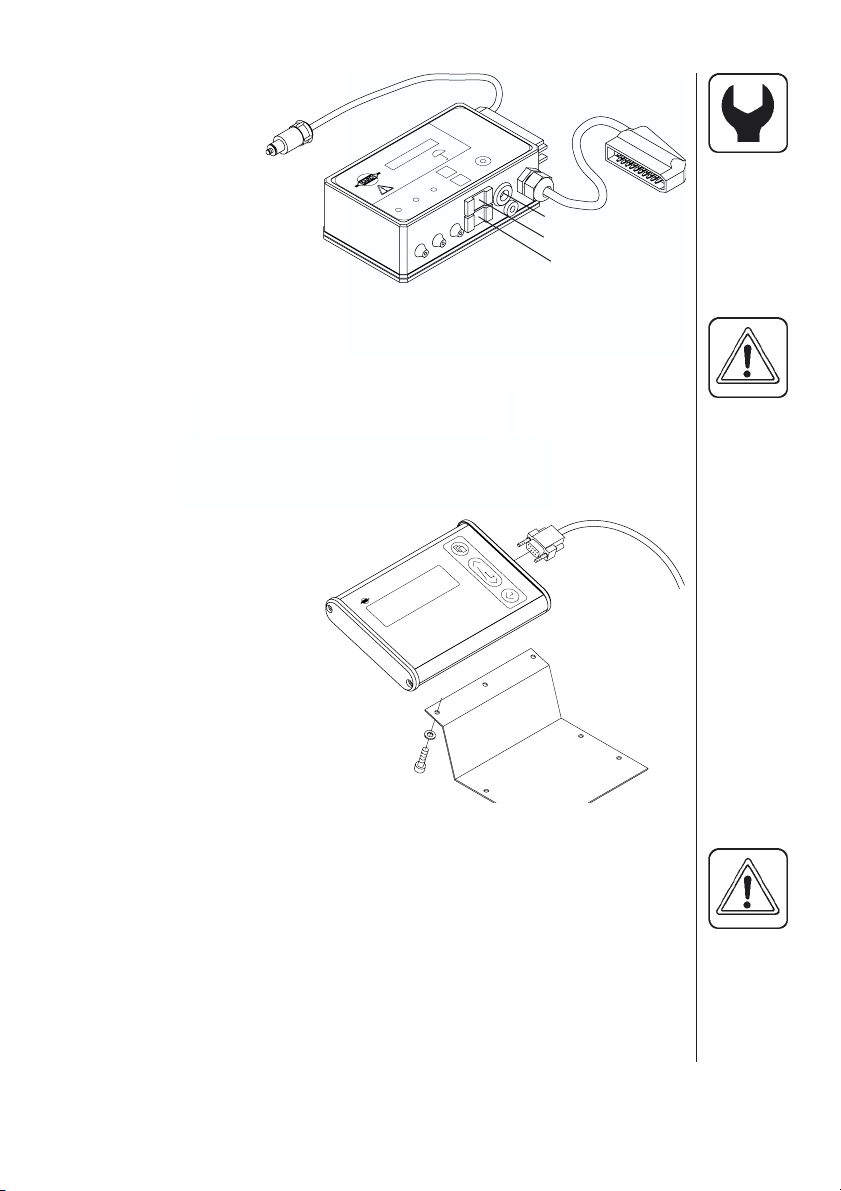
Display
The display is fitted in the
tractor cabin at a convenient
place. Use only the supplied
screws.
The mounting plate (A) is
utilised to fit the display together
with the switch box. The display can
also be fitted to a flat surface with
“Velcro” tape.
C
ABA
Place “ Quick guide” sticker at C
NOTE: Power must be disconnected before plug (B) is connected to
the display.
7
Page 8
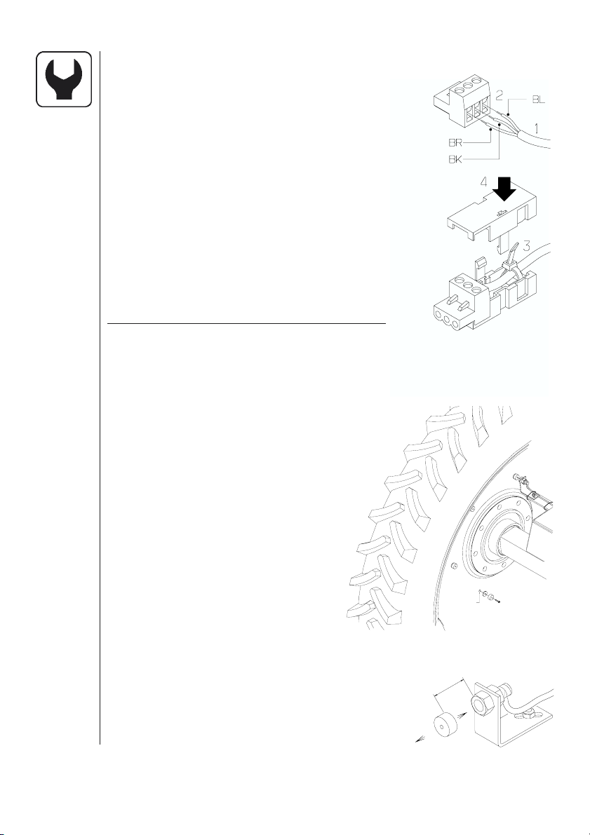
Transducer colour codes and plug assembly
1. Shorten cable to a suitable length.
2. Assemble as shown.
3. Run tie strap through hole under cable
grip and secure cable to plug housing.
4. Trim tie strap length and assemble the
housing. Tag the speed transducer by
folding the identification sticker around
the cable.
5. Secure plug housing with a tie strap.
HARDI transducers colour codes are as
follows. Includes speed, flow, area meter,
revolutions and pressure transducers.
Wire colour Code Connection for transducer
Brown BR 12 Volt supply
Black BK GND
Blue BL Signal
Speed transducer
Speed transducer is fitted as shown.
Hole size is 4.5 mm.
Magnets must be placed an equal
distance (and at least 150 mm) from one
another.
T165-0003
Recommended number of magnets
fitted are as follows:
Tractor front wheel
(rim size up to 20”) ........................ 4
Tractor rear wheel
(rim size over 20”) .........................6
4.5 mm
3
/16
Transmission drive-shaft ...............1
The south side of the magnet must
face the transducer.
Distance between them must be 5 to 7 mm.
T165-0004
1
5-7 mm
-
8
1
/
N
4
/
S
8
Page 9
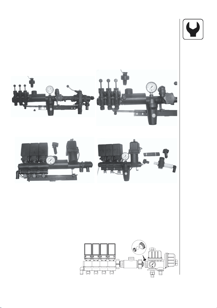
Flow transducer for BK, EVC and ESC control unit
For BK and EVC control unit, the housing is fitted just prior to the
distribution valves. Flow transducer is fitted to the housing and connected to the Scanbox with the a 3 poled plug.
For ESC control unit, the flow housing is fitted just prior to the control
unit on the delivery hose from the pump. Flow transducer is fitted to the
housing and connected to the Scanbox with the a 3 poled plug.
BK BK
EVC
ESC
Flow transducer EC control unit
1. The distribution valve unit is detached from the main ON/OFF
valve unit. Note the orientation of the ball seat and remove it from
the distribution valve unit.
2. Mount the flow transducer housing just before the distribution
valves.
3. Attach distribution valves with flow housing with the ball seat on
the end to main ON/OFF valve unit.
4. Flow transducer is fitted
to the housing and
connected to the
Scanbox with the
a 3 poled plug.
9
Page 10
Optional transducers
Revolutions and area-meter transducer
The south side of the
magnet must face the
transducer.
Distance between them
5-7 mm
must be 5 to 7 mm.
An adjustable hose clamp
drilled with a 4.5 mm hole
can be used to attach the
T165-0005
magnet to the shaft.
Analog transducer
Input is 4 to 20 mA.
Transducer cables are fed through the Scanbox grommets. Connection
is directly to the Scanbox circuit board.
NOTE: A 2 metre cable extension set with plugs and sockets is avail-
able. HARDI ref. no. is 741610.
5-7 mm
T165-0006
10
Connection pins
Cables
All the cables and wires must be routed so they do not get pinched,
snagged or melted. The transducer cables should be shortened if
necessary.
NOTE: Although the system meets standards EN 50081-1 (1992) for
generic emission and EN 50082-2 (1995) for generic immunity, some
communication systems (e.g. 2 way radio, cellular telephones) may
cause interference with the sprayer computer. Keep communication
system units and cabling away from the sprayer computer units and
cabling. If interference is noted, avoid using the communication system.
Page 11

Start-up
After connecting the plugs, the power is turned on at the Scanbox.
Model, version number and boom sections and size is displayed briefly.
Display
1. Matrix display, upper line.
2. Matrix display, lower line.
3. Key for menu.
4. Arrow keys.
• For programmed application rate.
With HM 1500, the value is used for the dose alarm.
• To get to (scroll).
• To alter a parameter.
5. Key to accept or get out of a menu.
NOTE: Press the keys with the underside of your finger.
Avoid using your fingernail.
1
3
4
2
Reading chosen volume rate
To read the chosen volume rate, press briefly either arrow keys
on the display. The chosen rate is shown.
CHANGE VOL. RATE
xxx L/ha
The main picture will return again after 5 seconds or if you press
accept key.
5
HM 1500: Changing the desired volume rate for alarm
The desired rate must be entered if you wish to operate with the alarm.
Press either arrow keys on the display. The rate per area is shown.
If the key is pressed again it will raise or lower the chosen rate.
When the key is released the display shows the new rate for a moment
and then returns to the main picture.
HC 2500: Changing the volume rate
The rate can be changed:
• Automatically, by changing the desired rate on the HC 2500 display.
• Manually, by raising and lowering the pressure on the control box.
11
Page 12

Automatic dosage
To alter the chosen application rate, press either arrow keys on the
display. The chosen quantity applied per area unit is shown. If the key
is pressed again it will raise or lower the chosen rate. When the key is
released the display shows the new rate for a moment and then
returns to the main picture.
NOTE: A minimum speed of 2.0 km/h is needed before the system will
regulate automatically.
Manual dosage
To dose in manual mode, use the pressure switch on the control box.
With HC 2500, the manual mode is indicated on the bottom line with a
flashed text [ MAN. ] over the displayed information. Bottom line is
cleared when [ MAN. ] is displayed.
MAN.
To go from manual to automatic dosage, briefly touch the arrow key
on the HC 2500.
Reading and reset of area trip
Area trip from 1 to 8 (Y) can be used for individual areas.
Area trip 0 is a tally of area trips 1 to 8. The treated area is memorised
when the system is switched off.
12
Area xxxx. xx ha
Y xxxxx L
1. Press enter key for area covered and volume sprayed.
2. Press enter key again to return. If is not pressed again it will return
to the main picture after 15 seconds.
To reset the active register press the enter key continuously and a
5 second countdown will commence.
Reset of a register can be stopped if the enter key is released.
Alarms
Alarm warnings [ Vol. rate alarm ] or [ Tank alarm ] are flashed for
3 seconds at a time on the top line over the displayed information.
Page 13

Menus
Parameter selection is carried out from the menu key.
The menus can be scrolled to and fro with the arrow keys.
The upper line, in capital letters, displays the menu you are in.
The lower line, in small letters, displays the choices you have. When the
chosen menu is shown, press the menu key again to open the menu.
When modifying a parameter, prolonged pressure on the arrow key will
generally cause the data shown on the display to alter faster.
After the parameter is modified, press the accept key.
The display then changes back to the previous picture.
Press the accept key until the display returns to the main display.
There are 2 menu systems, the operator menu for general use and an
extended menu for initial set-up of the system. To access the extended
menu, press both arrow keys at the same time until the menu changes.
General keystroke
Press to enter menus.
Press to find desired menu.
Press to enter menu.
Press to find desired sub-menu or alter parameter.
Press to continue in the menu if needed.
Press to accept and exit the menu.
Press Repeat to exit the menus and go back to the normal display
function.
13
Page 14

Keystroke menu tree chart
Press to read or alter (HC 2500) chosen volume rate.
Press to read or reset area trip.
Display readout
Tank contents
Main menu
Calibration
Volume rate
Program : Actual
Tank contents
Flow rate
Optional sensor
Revolutions
Speed
Active boom size
Flow calibration
Speed calibration
Revolutions
Boom sections/size
14
Alarms
Area/volume trip
Sensor test
Volume rate
Tank
Area 0 to 8
Flow
Speed
Area switch test
Revolutions
Optional sensor
Page 15

Main menu
The upper line will read [ MAIN MENU ].
The lower line displays the choices.
MAIN MENU
Display readout
To choose what is to be displayed on screen.
Tank contents
To change the indicated tank contents.
Calibration
To access calibration menus.
Alarms
To set alarm parameters.
Area/volume trip
To select register to record or read area covered and volume sprayed.
Sensor test
To test that the transducers function.
15
Page 16

Display readout
It is possible to freely choose which function is to be shown on the
upper or lower line of the display.
Show here
Show here
To choose where to show information.
Press arrow key to move [ Show here ] from the upper to lower line.
Press menu key to continue.
The upper line will read [ DISPLAY READOUT ].
The lower line displays the choices.
DISPLAY READOUT
Volume rate
To show the actual application rate.
Program:Actual
16
To show the programmed and actual application rate.
Tank contents
To show the tank contents.
If two tanks are used, the tank contents is the total contents.
Flow rate
To show the flow rate.
Page 17

Optional sensor
To show readout from optional analog transducer.
Revolutions
To show revolutions.
Speed
To show driving speed.
Active boom size
To see the active boom size.
Tank contents
If the sprayer is partially refilled or refilled the tank contents can be
adjusted.
See Extended menu to set tank size.
TANK CONTENTS
xxxx L
Press menu key and use arrow keys to raise or lower value.
17
Page 18

Calibration
It is necessary to set the correct boom width and calibrate the flow and
speed transducer before using the system. Calibration of the optional
revolutions transducer is necessary if it is fitted.
Boom size
CALIBRATION
Boom size set
For setting of number of boom sections and width.
Correct work width for each boom section is necessary
to calculate dosage and area covered.
Method
BOOM SIZE SET
Total sections x
1. Use arrow key to set number of boom sections and press menu key.
Maximum number of sections is 8. Press menu key to continue.
For mistblowers, number of sections is typically 2.
18
Sec. y Size x . xx m
2. Use the arrow key to increase or decrease section work width.
Press menu key to continue to next boom section.
After the last section, press the accept key.
The display will briefly show the total width.
Flow calibration
CALIBRATION
Flow calibration
Page 19

The flow transducer can be calibrated theoretically or with two practical
methods. For the sake of accuracy, the practical methods are preferred. Practical calibration is done with clean water. The Flow Tank
method is more time consuming, but is more accurate than the Flow
Nozzle method.
When changing to nozzles with more than a 100% increase or decrease
in output, it is recommended to re-calibration the flow transducer.
Calibration is recommended to be carried out at least once during the
spraying season.
Use the chart at the back of the book to record the values.
Flow constant
FLOW CALIBRATION
Flow constant
To change the flow constant theoretically.
During theoretical flow calibration the number of pulses per unit are
shown on the display.
For example, [ 120.0 PPU ] indicates the number of pulses which
theoretically come from the flow transducer whilst 1 litre of liquid
passes through. Approximate PPU values for different flow housings
are as follows:
Housing Code for Flow range PPU Orifice
housing l/min value mm
BK White 5 - 150 105.0 13.5
BK & EVC One outside groove 5 - 150 120.0 13.5
BK Black 10 - 300 60.0 20.0
EC White 5 - 150 118.0 13.5
EC Black 10 - 300 59.0 20.0
EC S/67 One outside groove 5 - 150 128.0 13.5
S/67 Two outside grooves 35 - 600 125.0 36.0
FLOW CONSTANT
xxx.x PPU
19
Page 20

Nozzle method
FLOW CALIBRATION
Nozzle method
During practical flow calibration the individual nozzle output on the
display is compared to the actual individual nozzle output.
The output displayed is corrected to read the actual output. For correct
calibration it is necessary to know the number of nozzles on the boom.
Method
NOZZLE METHOD
Total Nozzles xxx
1. The number of nozzles is set with the arrow key to read the actual
number of nozzles to spray. Press the menu key to continue.
2. Open all boom sections.
3. Turn the main ON/OFF valve on.
The display unit will then show the individual nozzle output per minute.
20
Flow xx.xx L/min
4. Using a HARDI calibration jug, check the actual nozzle output
per minute. It is recommended that an average of several nozzles
be taken.
5. Correct the output shown on the display with the arrow key to read
the average output measured with the calibration jug.
The display will briefly show the new calibration value PPU when
returning to the main display picture.
Page 21

Tank method
FLOW CALIBRATION
Tank method
During practical flow calibration the tank is partly emptied through the
nozzles. Whilst emptying, the display calculates the quantity emptied
on the basis of the actual calibration value (PPU). The quantity displayed is compared with the quantity actually dosed.
This can be according to the tank contents level indicator or by weight
difference before and after. The quantity displayed is corrected to read
the quantity actually dosed.
Method
1. Place the tank on level ground and fill up with water until the level
reaches a unique mark on the tank contents level indicator, e.g.
1000 litres.
2. Open all boom sections.
3. Open menu and turn the main ON/OFF valve on.
TANK METHOD
Sprayed xxxxL
The display unit will then begin to count the volume
being emptied through the nozzles.
4. When for example, 600 litres have been emptied out, as shown by
the tank contents level indicator, the main ON/OFF valve can be
turned off.
5. Correct the volume shown on the display with the arrow key to read
the volume shown on the tank contents level indicator. The display
will briefly show the new calibration value PPU when returning to
the main display picture.
21
Page 22

Speed calibration
CALIBRATION
Speed Calibration
The speed transducer can be calibrated theoretically or practically.
The practical method is recommended.
Speed constant
SPEED CALIBRATION
Speed constant
The theoretical speed constant, units per pulse (UPP), is the distance
in metre on the circumference of the wheel between magnets.
For example, if the wheel circumference is 2.00 m and
4 magnets are fitted, UPP is 0.5000.
SPEED CONSTANT
0.5 m
22
xxxxx UPP
Speed practical
SPEED CALIBRATION
Practical
Practical calibration of speed is done by driving a measured distance
and correcting the display so that the actual and the calculated
distances are the same.
Theoretical speed calibration should be carried out before practical
speed calibration.
Calibration should take place in the field with a half full tank and normal
working tyre pressure in order to obtain the wheel’s real “working radius”.
Page 23

Method
1. Measure a distance not less than 75 metres.
2. Park the tractor at the start of the measured distance.
3. Open menu. When zero distance [ 0 m ] shows, drive the meas-
ured distance.
PRACTICAL
Measured xxx m
4. Correct the distance shown on the display with the arrow key to
read the actual distance
Revolutions calibration
CALIBRATION
Revolutions cal.
For calibration of revolutions transducer.
REVOLUTIONS CAL.
x.x PPR
The constant, pulse per revolution (PPR), is
the number of pulses for one revolution.
For example, if one magnet is fitted, the PPR is 1.0.
Alarms
There are 2 alarms, a tank alarm for low tank contents and a volume
rate alarm for over or under application. When outside the alarm
parameters, the relevant warning will flash. A beeper can also be
activated.
ALARMS
Tank alarm
Low tank contents alarm.
23
Page 24

Activated at xx %
Suggested setting is 10%. For no alarm, set at 0 %.
Audio off
The beeper can be activated [ on ] or de-activated
[ off ] by pressing the arrow key.
ALARMS
Vol. rate alarm
Volume rate alarm for over or under application
for more than 20 seconds.
Activated at xx %
Suggested setting is 5%. For no alarm, set at 0 %.
24
Audio off
The beeper can be activated [ on ] or de-activated
[ off ] by pressing the arrow key.
Area/volume trip
It is possible to choose up to 9 area trip meters (0 to 8). [ Area 0 ] is a total
for all areas treated. When any of the other areas are used, the treated
area and volume will also be registered automatically in [ Area 0 ].
AREA/VOLUME TRIP
Area x
For reset of [ Area / Volume Trip ], see “Reset of area trip”.
Page 25

Sensor test
All readouts are in accumulated counts, i.e. one signal gives one
count, except for the optional (analog) transducer that is read in milliampere. Follow instructions on the display.
SENSOR TEST
Flow test
To test the flow sensor.
Spin rotor xxx
Remove transducer from flow housing and spin rotor.
Every second magnet will give a count, indicating correct function.
See also “Testing flow transducer”.
Speed test
To test the speed sensor.
Drive slowly xxx
Every magnet will give a count, indicating correct function.
See also “Testing speed transducer”.
Area switch test
To test the area-meter switch.
Magnet To Sens. Off
Without magnet.
25
Page 26

Magnet To Sens. On
With the south side of the magnet facing the transducer
at a distance of 5 to 7 mm. This indicates correct function.
Revolutions test
To test the revolutions sensor
Turn slowly xxx
Every magnet will give a count, indicating correct function.
Optional sensor
To test the optional transducer.
Area meter
For HM 1500 with manual control unit, the area
meter will register area continuously when the
sprayer is disconnected. When the south side of the
magnet is located directly in front of the transducer,
the area meter will stop registering area.
5-7 mm
26
When using a HM 1500 with manual control unit
and switch box, or HC 2500 with EC control box, all
the switches must be turned on.
If you do not want to utilise the area meter transducer, the main on/off
switch can be used to start and stop the area register.
T165-0006
Mistblowers and HM 1500/HC 2500
Points to note if the system is used on a mistblower.
• Work width is the same as the spray width of the mistblower.
• Not active switches on the control box are set to zero work width.
• Use the Tank method to calibrate the flow transducer.
• Blower fan revolutions can be read in the revolutions readout.
Page 27

Storage
When the tractor and sprayer is parked, disconnect the power supply
to the Scanbox. This will stop the system from using power.
The display and Scanbox should be protected from moisture and
should be removed if the tractor does not have a cabin.
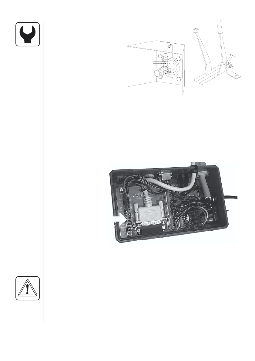
Emergency operation
The system is added to a standard electric control unit without any
modifications to the wiring. Should there be a problem when using the
HC 2500 disconnect the Scanbox from the control unit and connect the
cable from the control unit to the control box.
Spraying can now be continued.
Fault finding
Fault Cause Remedy
No start-up. Check polarisation is correct.
Blinking back-light. Poor power supply. Check battery, cabling and
No “bip” sound at start-up. connections.
Displayed area larger Field was not rectangular.
than actual area. “Tramlines” narrower than Measure “tramline” width.
Displayed volume larger Pressure equalisation valve Replace seals
than actual volume. leaks.
Check the fuse in the Scanbox. Change fuse. (use 1.25 T Amp).
spray width.
.
Fine tuning the flow constant - PPU
Calibration of the flow transducer is carried out with clean water but
small changes may occur when adding pesticides or fertiliser.
This will effect the final readings. This is typically noted when the
volume displayed on the display does not equal the actual known
volume that was sprayed out. The below formula can be used to
“fine tune” the flow transducer PPU.
New PPU =
Original PPU x Displayed Volume
Sprayed Volume
For example, the spray tank is filled with 2400 litres of spray liquid.
When sprayed out, the display showed a total of 2300 litres.
(Original PPU = 120.0)
New PPU =
120.0 (Original PPU) x 2300 (Displayed Volume) = 115.0
2400 (Sprayed Volume)
27
Page 28

Note the relation is inverse:
• To raise the displayed volume, the PPU is lowered.
• To lower the displayed volume, the PPU is raised.
Testing flow transducer (Ref. no. 728816)
Wire connections: BROWN wire to positive of 12 volt battery.
BLACK wire to negative.
BLUE wire to multimeter positive.
1. Check the rotor turns freely.
2. Each vane in the rotor has a magnet in it
N
S
with the pole facing out.
Check that the 4 magnets are present.
S
N
3. Check every second magnet has the
same pole orientation so the rotor
magnets are N - S - N - S.
4. Connect negative from multimeter to
negative of battery.
T045-0003
5. Set multimeter to DC volt.
6. By turning the mill wheel slowly, this will register approx. 8.0 +/- 1 volt
with the diode on and 0.3 +/- 0.1 volt with the diode off with every
second magnet.
Testing speed transducer (Ref. no. 729058)
Wire connections: BROWN wire to positive of 12 volt battery.
BLACK wire to negative.
BLUE wire to multimeter.
4
1
1. Connect negative from multimeter to
negative of battery.
5-7 mm
-
8
1
/
/
2. Set multimeter to DC volt.
3. By bringing the south pole of a magnet
(distance 5 mm +/- 2 mm) by the trans
ducer, this will register 0.3 +/- 0.1 volt.
S
N
T165-0004
4. By removing the magnet, this will register 7 .0 +/- 1.0 volt.
28
Page 29

Technical specifications
Supply voltage 12 Volt DC
Minimum supply 11 Volt DC
Maximum supply 16 Volt DC
Maximum peak 20 Volt DC
Ambient temperature – 10° C to + 55° C
Memory Flash PROM non-volatile
Digital transducers Square signal
Update frequency 4 times per second
Trigger high 5.0 to 12.0 Volt DC
Trigger low 0.0 to 0.5 Volt DC
Analog transducers
Supply Loop
Input 4 to 20 mA
Minimum speed for volume regulation 2.0 km/h
Flow ranges for the flow transducers
Identification code Orifice Flow
White 13.5 mm 5 to 150 l/min
Black 20.0 mm 10 to 300 l/min
One outside groove 13.5 mm 5 to 150 l/min
Two outside grooves 36.0 mm 35 to 600 l/min
Pressure drop over 13.5 mm orifice is 1 bar at 150 l/min.
Packaging information
Materials used for packaging are environmentally compatible.
They can be safely deposited or they can be burnt in an incinerator.
Recycling
Cardboard: Can recycle up to 99% and therefore should be put into
the waste collection system.
Polyethylene: Can be recycled.
When the HM 1500 / HC 2500 has completed its working life, it must
be thoroughly cleaned. The synthetic fittings can be incinerated.
The printed circuit boards and metallic parts can be scrapped.
29
Page 30

Chart for recording values
Menu Function 1 - Values 2 - Values 3 - Values
Nozzle /Colour
[ Flow constant ] Flow PPU
[ Speed constant ] Speed UPP
Extended menu
Access the extended menu by pressing both arrow keys at the same
time until the menu changes.
The extended menu written in English only.
NOTE: Re-start the system after leaving the Extended menu.
Menu Function [ choices ]
[ Language ] To select language.
[ GB, DK, F, E, D, Cz, SF, NL, I, S ]
[ Unit ] To set unit of measurement. [ Metric, USA ]
[ ON/OFF valve ] To select EC or EVC/ESC/CB control unit.
[ Present, not present ]
[ Pressure system ] To select pressure system.
[ Equalisation, No equalisation ]
[ Control box ] To indicate control box connection to Scanbox.
[ Connected, Not connected ]
[ Tank volume max ] To pre-set tank volume indicated at start-up.
[ Analog adjust ] To calibrate the optional transducer.
[ max., min., offset in mA ]
[ Analog unit text ] To choose the unit of measurement.
[ Bar, PSI, deg C, deg F, % R.H ]
[ Regulation con. ] For the sensitivity of the pressure regulation
valve.
[ Change SW ver. ] To permit change or update of software.
[ Master reset ] For factory use only.
[ Area totals ] To see total area covered and volume sprayed.
[ Scanbox] For factory use.
30
Page 31

Default setting
Text For HC 2500* For HM 1500**
[ Language ]GB GB
[ Unit ] Metric Metric
[ ON/OFF valve ] Present Present
[ Pressure system ] Equalisation Equalisation
[ Control box ] Connected Not Connected
[ Tank size ] 2000 l 2000 l
[ Analog adjustment ] max. 10 max. 10
min. 0 min. 0
offset in mA 0 mA offset in mA 0 mA
[ Analog unit text ] Bar Bar
[ Regulation con. ]0% 0%
[ Flow PPU ] 120.0 120.0
[ Speed UPP ] 1.0000 1.0000
HC 2500*
For EVC, ESC or CB control unit set:
[ ON/OFF valve ] to [ Not present ]
HM 1500**
For BK, BK/EC or EC control unit with switch (control) box for boom sections set:
[ Control box ] to [ Connected ]
For EVC, ESC or CB control unit set:
[ ON/OFF valve ] to [ Not present ]
[ Control box ] to [ Connected ]
NOTE: Re-start the system after leaving the Extended menu.
31
Page 32

EC Declaration of Conformity
Manufacturer,
HARDI INTERNATIONAL A/S
Helgeshøj Allé 38
DK 2630 Taastrup
DENMARK
Importer,
declare that the following product;
○○○○○○○○○○○○○○○○○○○○○○○○○○○○○○○○○○○○○○○○
○○○○○○○○○○○○○○○○○○○○○○○○○○○○○○○○○○○○○○○○
Adhere extra shipping package labels to inside cover.
○○○○○○○○○○○○○○○○○○○○○○○○○○○○○○○○○○○○○○○○
32
was manufactured in conformity with the provisions in the EMC directive 89/336/EEC, EN 50081-1 (1992) (generic emission) and EN
50082-2 (1995) (generic immunity).
Taastrup 15/09/2002
Lars Bentsen
Product Development Manager
HARDI INTERNATIONAL A/S
Page 33

333435
Page 34

Page 35

Page 36

36
 Loading...