

Page 1

The Sprayer
Operator’s Manual
EAGLE™ SPB/SPC BOOM
Instruction book
67024003 - Version 1.10
US - 06.2015
Page 2

Page 3

EAGLE™ SPB/SPC BOOM
HARDI® reserves the right to make changes in design, material, or specification without notice thereof.
HARDI® and other product names are registered trademarks of HARDI® Inc. in the U.S. and in other countries.
Instruction book
67024003 - Version 1.10
US - 06.2015
Page 4

Page 5

Table of contents
1 - Welcome
Welcome letter ......................................................................................................................................1
2 - Safety notes
Operator safety .....................................................................................................................................1
Symbols ........................................................................................................................................................................................................................ 1
General info ............................................................................................................................................................................................................... 1
Local poison information center ...........................................................................................................2
3 - Description
Boom .....................................................................................................................................................1
Boom types and sizes .......................................................................................................................................................................................... 1
Hydraulic systems .................................................................................................................................................................................................. 1
Boom terminology ................................................................................................................................................................................................ 2
Electrical Hydraulic controls ..................................................................................................................3
General info ............................................................................................................................................................................................................... 3
HV Hydraulic control box (Ranger 550) .................................................................................................................................................... 3
HZ Hydraulic control box (Ranger 550) .................................................................................................................................................... 3
HZ Hydraulic control box (Ranger 2000, Navigator) ........................................................................................................................ 3
HZ Hydraulic control box - 90’/60’ SPC Dual Fold booms (Navigator) ................................................................................. 4
HZ Hydraulic control box - 120’/90’ SPC Dual Fold booms (Navigator) .............................................................................. 4
SetBox controls for sprayers equipped with ISOBUS ....................................................................................................................... 5
HZ Hydraulic controls on the Grip handle (ISOBUS & PRESIDIO) .............................................................................................5
HZ Hydraulic controls on the HARDI® spray center (PRESIDIO) ................................................................................................ 5
4 - Sprayer setup
Hydraulic systems .................................................................................................................................1
General info ............................................................................................................................................................................................................... 1
Requirements - tractor (SPB/SPC HY-model) ........................................................................................................................................ 1
Requirements - tractor (SPB HV-model) ................................................................................................................................................... 1
Requirements - tractor (SPB/SPC HZ-model) ........................................................................................................................................2
HZ hydraulic block ................................................................................................................................................................................................3
Open center hydraulics (trailed - optional equipment) ................................................................................................................. 3
Boom .....................................................................................................................................................4
Suspension effect adjustment (80’-100’ SPC only) ............................................................................................................................ 4
5 - Operation
Boom .....................................................................................................................................................1
Safety info ................................................................................................................................................................................................................... 1
Maneuvering of the SPB booms - HY version (Ranger) .................................................................................................................. 2
Maneuvering of the SPB and SPC booms - HY version (Navigator) .......................................................................................2
Maneuvering of the SPB booms - HV version (Ranger 550) ........................................................................................................ 3
Maneuvering of the SPB booms - HZ version (Ranger 550) ........................................................................................................ 4
Maneuvering of the SPB booms - HZ version (Ranger 2000) ..................................................................................................... 5
Maneuvering of the SPB and SPC booms - HZ version (Navigator) .......................................................................................6
Maneuvering of the 90’/60’ SPC Dual Fold boom (Navigator) ..................................................................................................7
Single-sided folding of the 90’/60’ SPC Dual Fold boom (Navigator) ................................................................................... 8
Maneuvering of the 120’/90’ SPC Dual Fold boom (Navigator) ................................................................................................ 9
Maneuvering of the SPB booms - (Ranger with ISOBUS) ........................................................................................................... 10
Maneuvering of the SPB, SPC & 90’/60’ Dual Fold SPC booms - (Navigator with ISOBUS) ...................................11
Maneuvering of the 120’/90’ Dual Fold SPC booms - (Navigator with ISOBUS) .......................................................... 12
Maneuvering of the SPC booms (PRESIDIO) ...................................................................................................................................... 13
Maneuvering of the 90’/60’ Dual Fold SPC boom (PRESIDIO) ................................................................................................. 14
TOC. 1
Page 6

Table of contents
6 - Maintenance
Lubrication ............................................................................................................................................1
General info ............................................................................................................................................................................................................... 1
Recommended lubricants ............................................................................................................................................................................... 1
45’-60’ SPB & 80’-100’ SPC Boom lubrication & oiling plan .......................................................................................................... 1
120’/90’ & 90’/60’ Dual Fold SPC Boom lubrication & oiling plan ............................................................................................ 2
Service and Maintenance intervals .......................................................................................................3
10 hours service - In-Line filter ....................................................................................................................................................................... 3
10 hours service - Nozzle filters (optional equipment) ................................................................................................................... 3
10 hours service - Spraying circuit ............................................................................................................................................................... 3
250 hours service - Readjustment of the boom ................................................................................................................................. 3
250 hours service - Hydraulic circuit .......................................................................................................................................................... 3
250 hours service - Hoses and tubes ......................................................................................................................................................... 3
Occasional maintenance ........................................................................................................................4
General info ............................................................................................................................................................................................................... 4
Nozzle tubes and fittings ..................................................................................................................................................................................4
Feed pipe snap-lock assembly (T25) .......................................................................................................................................................... 4
Feed pipe clamp assembly (T25) .................................................................................................................................................................. 5
Readjustment boom - general info ............................................................................................................................................................5
Alignment of center and inner wing sections (All booms) .......................................................................................................... 5
Alignment of inner and outer wing sections (All booms) ............................................................................................................ 6
Hydraulic stop valve adjustment (Dual Fold SPC only) .................................................................................................................. 6
Adjusting the front fold cable (All booms) ............................................................................................................................................. 7
Breakaway section adjustment (45’-66’ SPB) ........................................................................................................................................7
Breakaway section adjustment (80’-100’ & Dual Fold SPC) .......................................................................................................... 8
Check/adjust sprocket timing (45’-66’ SPB) ........................................................................................................................................... 8
Adjusting boom level to ground (All booms) ...................................................................................................................................... 9
Adjusting rear cable (All booms) ............................................................................................................................................................... 10
Adjusting center section cables (All except 120’/90’ Dual Fold) ........................................................................................... 10
Yaw rubber dampers (80’-100’ SPC, 90’/60’ Dual Fold SPC) .....................................................................................................11
Yaw rubber dampers (120’/90’ Dual Fold SPC) ................................................................................................................................. 11
Yaw damping (All booms) ............................................................................................................................................................................. 11
7 - Fault finding
Operational problems ...........................................................................................................................1
General info ............................................................................................................................................................................................................... 1
Hydraulic system - I.A.H. .................................................................................................................................................................................... 2
Mechanical problems ............................................................................................................................3
Mechanical problems ......................................................................................................................................................................................... 3
8 - Technical specifications
Specifications ........................................................................................................................................1
Filters and nozzles ................................................................................................................................................................................................. 1
Temperature and pressure ranges .............................................................................................................................................................. 1
Electrical connections ............................................................................................................................2
Plug positions for HZ hydraulics ................................................................................................................................................................... 2
Plug positions for HZ hydraulics (120’/90’ Dual Fold boom) ...................................................................................................... 2
Plug positions for HZ hydraulics (90’/60’ Dual Fold boom) ......................................................................................................... 2
Charts ....................................................................................................................................................3
Boom hydraulics - HY (45’-66’ SPB Ranger) ............................................................................................................................................ 3
Boom hydraulics - HY (45’-66’ SPB & 75’-100’ SPC Navigator) .................................................................................................... 3
Boom hydraulics - HZ (45’-66’ SPB Ranger) ............................................................................................................................................ 4
Boom hydraulics - HZ (45’-66’ SPB & 75’-100’ SPC Navigator) .................................................................................................... 4
Boom hydraulics - 90’/60’ Dual Fold SPC (Navigator) ...................................................................................................................... 5
Boom hydraulics - 120’/90’ Dual Fold SPC (Navigator) ................................................................................................................... 5
Boom hydraulics - 75’-90’ SPC (PRESIDIO) .............................................................................................................................................. 6
Boom hydraulics - 90’/60’ Dual Fold SPC (PRESIDIO) ....................................................................................................................... 6
9 - Warranty
Warranty policy and conditions ............................................................................................................1
TOC. 2
Page 7

1 - Welcome
Welcome letter
Dear New HARDI® Owner,
Thank you for purchasing your new HARDI® product and welcome to the ever-increasing family of proud HARDI® owners.
HARDI® is the leading sprayer company in offering growers strong, reliable products made for the widest range of
applications worldwide. Quality, reliability, and resale value make the HARDI® product line the preferred product line of
customers both in North America as well as worldwide. Our guiding principle is to provide the highest level of customer
satisfaction and long term value in the marketplace today. We have developed a very high level of customer loyalty in the
marketplace which we are very proud of and strive every day to maintain and to continue to grow.
HARDI® is your specialist in spraying and we spend all of our time and keep all of our focus on spraying. We do not share our
resources between other types of products or compromise on anything in providing the best quality sprayers to the market
today. We can provide the latest in technology with our products if desired, or allow them to operate with the technology
that you already use on other products in most cases. You get to decide that, and what best suits your needs. We feel that
you, our customer, are the best suited to answer that question for your operation. Either way, you decide, and we will try and
help make it happen for you.
Our broad spectrum of product offerings, from the ruggedly simple models we build to our highly sophisticated models,
the built-in HARDI® strength and reliability ensures a low cost of ownership. HARDI® sprayers are all based on a functional
design concept of being as simple to operate as possible and to meet our customers’ requirements for all their application
needs.
Please take the time to thoroughly read the Operator’s Manual before using your equipment. You will find many helpful hints
as well as important safety and operation information.
Some of the features on your HARDI® sprayer were suggested by growers. There is no substitute for “on farm” experience
and we invite your comments and suggestions. If any portion of this instruction book remains unclear after reading it,
contact your HARDI® dealer or service personnel for further explanation before using the equipment.
For Product, Service or Warranty Information please contact your local HARDI® dealer.
- Please use the HARDI® Customer Service number: 1-866-770-7063
- Or send your email to CUSTSERV@hardi-us.com
HARDI® NORTH AMERICA INC.
Visit us online at: www.hardi-us.com
1500 West 76th St.
Davenport, Iowa 52806
Phone: (563) 386-1730
Fax: (563) 386-1280
Sincerely,
Wayne Buchberger
President
1.1
Page 8

1 - Welcome
1.2
Page 9

2 - Safety notes
Operator safety
Symbols
These symbols are used throughout the book to designate where the reader needs to pay extra attention.
This symbol means DANGER. Be very alert as your safety is involved!
€
This symbol means WARNING. Be alert as your safety can be involved!
±
This symbol means ATTENTION. This guides to better, easier and safer operation of your sprayer!
This symbol means NOTE.
÷
General info
Before using the sprayer, read the following recommendations and safety instructions.
• Read and understand this instruction book before using the equipment. It is equally important that other operators of
this equipment read and understand this book.
• If any portion of this instruction book remains unclear after reading it, contact your HARDI® dealer for further
explanation before using the equipment.
• Local law may demand that the operator is certified to use spray equipment. Adhere to the law.
• Wear protective clothing. Wash and change clothes after spraying.
• Wash tools if they have become contaminated. Rinse and wash equipment after use and before servicing.
• Never service or repair the equipment while it is operating.
• Always replace all safety devices or shields immediately after servicing.
• Do not eat, drink or smoke while spraying or working with contaminated equipment.
• In case of poisoning, immediately seek medical advice. Remember to identify chemicals used.
• Keep children away from the equipment.
• Be careful not to hit people or surroundings when maneuvering the sprayer, especially when backing.
• Do not fold or unfold boom near overhead wires. Serious injury or death could result if contact is made with electric
wires.
• Slow down when driving in uneven terrain, as the machine might be in risk of turning over.
• Pressure test with clean water prior to filling with chemicals.
• Disconnect electrical power before servicing and depressurize equipment after use and before servicing.
• Do not go under any part of the sprayer unless it is secured. The boom is secure when placed in the transport brackets
with rear transport lock secured.
• If an arc welder is used on the equipment or anything connected to the equipment, disconnect power leads before
welding. Remove all flammable or explosive material from the area.
2.1
Page 10

2 - Safety notes
Local poison information center
If you live anywhere in the United States, the following toll free number will connect you to your Local Poison
€
Information Center.
PHONE NO. 1 - 800 - 222 - 1222
If you live outside the United States, find the number for the poison control center in your phone book and write it
€
in the space below:
PHONE NO._______ - _______ - __________
Keep a list, in the space provided below, of all the chemicals that you have in use.
€
1. _______________________________________________________________________________________________
2. _______________________________________________________________________________________________
3. _______________________________________________________________________________________________
4. _______________________________________________________________________________________________
5. _______________________________________________________________________________________________
6. _______________________________________________________________________________________________
7. _______________________________________________________________________________________________
8. _______________________________________________________________________________________________
9. _______________________________________________________________________________________________
10. ______________________________________________________________________________________________
2.2
Page 11

3 - Description
Boom
Boom types and sizes
The HARDI® EAGLE™ booms are available in the following types and sizes:
SPB sizes: 45’, 50’, 60’ & 66’
The 45’ - 66’ SPB booms are built with the same basic components. There are differences in the outer wing sections to give
the range of boom widths. The 45’ & 50’ booms incorporate the breakaway into the folding hinge point between the inner/
outer wings. The 60’ & 66’ booms include breakaway sections in the outer wing.
SPC sizes: 75’, 80’, 88’, 90’ & 100’
The 75’ - 100’ SPC booms are built with the same basic components as the SPB booms. The main differences are in the size
of the boom steel profiles, the folding hinge area between the inner/outer wings and the type of breakaway sections.
SPC Dual Fold sizes: 90’/60’ & 120’/90’
The SPC booms are also available in Dual Fold models; 90’/60’ & 120’/90’. The outer sections of the dual fold booms fold
vertically to allow for two different spraying widths.
Components cannot be exchanged between the EAGLE™ SPB and SPC booms. Also, the 120’/90’ Dual Fold SPC booms are
equipped with a different center section than the other SPC booms.
Note: Individual boom wing fold is not possible using the 120’/90’ Dual Fold SPC booms.
÷
Hydraulic systems
The HARDI® EAGLE™ booms are available in four different hydraulic system versions; HY, HV, HZ (trailed) & HZ (self-propelled).
1. SPB-HY & SPC-HY
These types of booms are operated directly via the tractor hydraulics. Hydraulic lift cylinders are used for boom height
adjustment and fold cylinders are used for simultaneous boom wing fold and unfold.
2. SPB-HV
This type of boom has the same features as the HY model, but also allows for individual boom wing fold and unfold.
Hydraulic lift cylinders are used for boom height adjustment and fold cylinders are used for individual boom wing fold and
unfold. The SPB-HV hydraulics are controlled with an electrical hydraulic control box.
3. SPB-HZ & SPC-HZ (trailed)
These types of booms have two boom wing tilt cylinders that give the ability to obtain individual boom wing tilt. Hydraulic
lift cylinders are used for boom height adjustment and fold cylinders are used for individual boom wing fold and unfold. The
hydraulics are controlled with various different electrical hydraulic controls depending on the model of sprayer.
4. SPC-HZ (self-propelled)
This type of boom has two boom wing tilt cylinders that give the ability to obtain individual boom wing tilt. Hydraulic lift
cylinders are used for boom height adjustment and fold cylinders are used for simultaneous boom wing fold and unfold.
The hydraulics are controlled with the HARDI® Spray center and the multifunctional Grip handle.
Note: Individual boom wing fold is not possible using the HY Hydraulic system (1) or the HZ self-propelled system (4).
÷
3.1
Page 12

3 - Description
Boom terminology
The terminology for the SPB/SPC boom sections is as follows:
A - Breakaway section
B - Outer section
C - Inner section
D - Center section
Note: The outer sections (B) on the 45’ & 50’ SPB booms are also the breakaway sections (A). So A & B are combined.
÷
The terminology for the Dual Fold SPC boom sections is as follows:
A - Breakaway section
B - 2nd Outer section
C - 1st Outer section
D - Inner section
E - Center section
3.2
Page 13

3 - Description
Electrical Hydraulic controls
General info
The electrical controls used to operate the boom hydraulics vary depending on the model of sprayer.
HV Hydraulic control box (Ranger 550)
The switches on the HV hydraulic control box control the following
functions:
1. Power ON/OFF
2. Boom folding (left side)
3. Boom lift raise/lower
4. Boom folding (right side)
HZ Hydraulic control box (Ranger 550)
The switches on the hydraulic control box control the following
functions:
1. Power ON/OFF
2. Boom tilt left
3. Boom tilt right
4. Boom folding (left side)
5. Boom lift raise/lower
6. Boom folding (right side)
HZ Hydraulic control box (Ranger 2000, Navigator)
The switches on the hydraulic control box control the following
functions:
1. Power ON/OFF
2. Boom tilt left
3. Boom lift raise/lower
4. Boom tilt right
5. Boom folding (left side)
6. Boom folding (right side)
7. Optional function
8. Optional function
3.3
Page 14

3 - Description
HZ Hydraulic control box - 90’/60’ SPC Dual Fold booms (Navigator)
The switches on the hydraulic control box control the following
functions:
1. Power ON/OFF
2. Boom tilt left
3. Boom lift raise/lower
4. Boom tilt right
5. Boom folding (left)
6. Boom folding (outer)
7. Boom folding (right)
8. Optional function
9. Optional function
HZ Hydraulic control box - 120’/90’ SPC Dual Fold booms (Navigator)
The switches on the hydraulic control box control the following
functions:
1. Power ON/OFF
2. Boom tilt left
3. Boom lift raise/lower
4. Boom tilt right
5. Boom folding (main)
6. Boom folding (outer)
7. Optional function
8. Optional function
3.4
Page 15
3 - Description
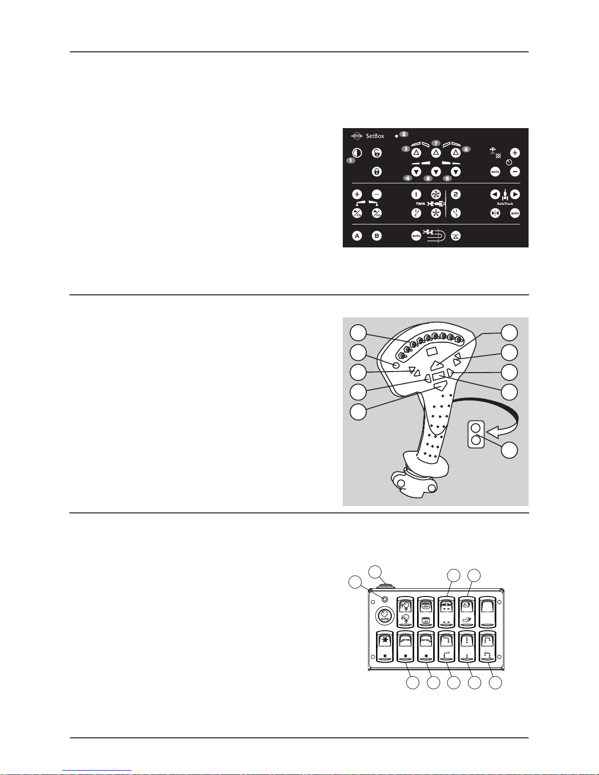
SetBox controls for sprayers equipped with ISOBUS
The SetBox controls secondary functions. The keys are grouped into control areas to simplify operator understanding.
Note: Self-propelled sprayers do not have a SetBox as the controls are built-in to the cabin.
÷
1. Power ON/OFF.
2. Status diode.
3. Left boom fold.
4. Left boom unfold.
5. Right boom fold.
6. Right boom unfold.
7. 2nd outer section fold (Dual Fold booms only).
8. 2nd outer section unfold (Dual Fold booms only).
ATTENTION! The Grip cannot be switched ON/OFF separately. It is automatically switched ON when tractor power is
turned ON (ISOBUS).
HZ Hydraulic controls on the Grip handle (ISOBUS & PRESIDIO)
A. Status LED.
B. Boom section controls.
C. Main ON/OFF.
D. Tilt.
E. Boom height.
F. Boom slant.
G. Not used.
B
A
D
F
E
E
D
F
C
G
HZ Hydraulic controls on the HARDI® spray center (PRESIDIO)
The boom controls on the HARDI® spray center work in combination with the Grip controls. The buttons on the console
control the following functions:
1. Status LED.
2. Main ON/OFF.
3. Unfold/Fold boom.
4. Unfold/Fold second outer section (90’/60’ booms only).
5. Left End Nozzle ON/OFF (optional).
6. Right End Nozzle ON/OFF (optional).
7. Foam Marker Left/Right.
8. Foam Marker blob interval.
9. Foam Marker Inner/Outer (optional).
2
1
5 6 7 8 9
3 4
3.5
Page 16

3 - Description
3.6
Page 17

4 - Sprayer setup
Hydraulic systems
General info
Ensure that snap couplers are clean before connection!
After having operated the boom and the system has been filled with oil, check tractor’s hydraulic oil level and add oil if
necessary.
DANGER! Test of the hydraulic system should be done very cautiously. There may be air trapped in the system which
€
can cause violent movements of the boom.
DANGER! Hydraulic leaks: Never use your fingers to locate a leakage in any part of the hydraulic system. Due to high
€
pressure, hydraulic oil may penetrate the skin.
Requirements - tractor (SPB/SPC HY-model)
Connection requirements are:
• One single acting outlet for the lift function of the spray boom.
• One double acting outlet for the folding function.
Ensure that snap couplers are clean before connection!
The boom’s hydraulic system requires an oil flow of approximately 0.8 GPM (3 liters/min.) and a minimum pressure of 1,950
PSI (130 bar).
ATTENTION! After having operated the boom and the system has been filled with oil, then check tractor’s hydraulic
oil level and add oil if necessary.
WARNING! Due to the variation in tractor hydraulic systems and capacities, care should be exercised when initially
±
operating the sprayer hydraulic cylinders. It is advisable to adjust the hydraulic flow control down to the minimum
rate before operating the system. Adjust/increase the flow control after the system is bled of any air, if necessary.
Requirements - tractor (SPB HV-model)
Connection requirements are:
• One double acting outlet for the lift and folding function of the spray boom.
Ensure that snap couplers are clean before connection!
The hydraulic hoses are marked with arrows and colored tie straps to indicate direction of oil flow. Red tie strap = pressure.
Green tie strap = Return to tank. The hoses must be hooked up to the correct outlet for the hydraulics to function properly
(pressure hose to pressure outlet, return hose to tank outlet).
The boom’s hydraulic system requires an oil flow of approximately 0.8 GPM (3 liters/min.) and a minimum pressure of 1,950
PSI (130 bar).
ATTENTION! After having operated the boom and the system has been filled with oil, then check tractor’s hydraulic
oil level and add oil if necessary.
WARNING! Due to the variation in tractor hydraulic systems and capacities, care should be exercised when initially
±
operating the sprayer hydraulic cylinders. It is advisable to adjust the hydraulic flow control down to the minimum
rate before operating the system. Adjust/increase the flow control after the system is bled of any air, if necessary.
4.1
Page 18

4 - Sprayer setup
Requirements - tractor (SPB/SPC HZ-model)
Connection requirements are:
• One double acting hydraulic outlet for the lift and folding functions of the sprayer.
Ensure that snap couplers are clean before connection!
The hydraulic hoses are marked with arrows and colored tie straps to indicate direction of oil flow. Red tie strap = pressure.
Green tie strap = Return to tank. The hoses must be hooked up to the correct outlet for the hydraulics to function properly
(pressure hose to pressure outlet, return hose to tank outlet).
The boom’s hydraulic system requires an oil flow of approximately 0.8 GPM (3 liters/min.) and a minimum pressure of 1,950
PSI (130 bar).
ATTENTION! After having operated the boom and the system has been filled with oil, then check tractor’s hydraulic
oil level and add oil if necessary.
WARNING! Due to the variation in tractor hydraulic systems and capacities, care should be exercised when initially
±
operating the sprayer hydraulic cylinders. It is advisable to adjust the hydraulic flow control down to the minimum
rate before operating the system. Adjust/increase the flow control after the system is bled of any air, if necessary.
4.2
Page 19
HZ hydraulic block
The hydraulic flow can be adjusted on the HZ hydraulic block if
necessary. First set the hydraulic flow on the tractor so the boom raises
and lowers at the desired speed. Then check the speed of the fold and
tilt functions. If adjustment is necessary, loosen jam nut (A) and turn
throttle valve (B) all the way in using an allen wrench. Then turn throttle
valve (B) back out 1-1/2 turns. If the fold and tilt functions are too slow,
turn throttle valve (B) out more. If the fold and tilt functions are too fast,
turn throttle valve (B) in more. Tighten jam nut (A) when the desired
speed is reached.
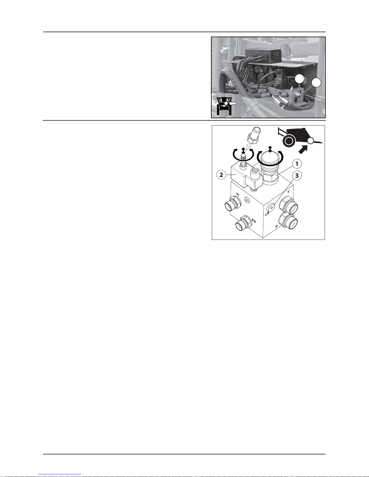
Open center hydraulics (trailed - optional equipment)
The open center hydraulic block is needed if the tractor uses open
center hydraulics and/or if load sensing will be used.
The valve (1) on the side of the block is factory set for open center
hydraulics, but if closed center hydraulics will be used (also in
combination with load sensing) then screw in the valve.
Certain tractor models are able to use Load Sensing without connecting
an external sensing line. But if optimal sensing control pressure cannot
be obtained, an external sensing line needs to be mounted (3). Please
consult your tractor dealer for correct setup and correct connection.
Before operating the hydraulics, the valve should be adjusted according
to the specific tractor model. If you have doubt about which type of
hydraulic system your tractor is equipped with, please consult your
tractor dealer.
List of setting combinations for flow element and circuit value:
Valve no. 1 2 3 (LS port)
Open center out out Not conn.
Closed center in in Not conn.
Load sensing (LS) in out* Connected
*if tractor requires pressure relief.
4 - Sprayer setup
A
B
WARNING! Always be sure to fully extract or retract the open/closed center selection valve (1). Failure to do so can
±
result in damages to vital pump parts.
WARNING! It is of essential importance that connectors on sensing line are kept totally clean. Failure to do so can
±
result in impurities entering the pump and thereby cause damages to vital pump parts.
4.3
Page 20

4 - Sprayer setup
Boom
Suspension effect adjustment (80’-100’ SPC only)
The SPC boom features adjustable suspension for 80’-100’ booms. The
spring (A) has two assembly positions as shown on the illustration
below. Position (1) can be used for 80’-90’ booms and position (2) can be
used for 100’ booms.
Moving the assembly position further away from center (e.g. from pos. 1
to pos. 2) gives stiffer trapeze effect. The factory setting is position (1).
4.4
Page 21

5 - Operation
Boom
Safety info
WARNING! The boom must not be folded/unfolded while driving! Never use the folding/unfolding functions before
±
sprayer has been stopped! Failure to do so will cause damage to the boom.
DANGER! When folding or unfolding the boom, make sure that no persons or objects are in the operating area of the
€
boom.
DANGER! Always follow the guidelines listed below when driving
€
in areas with overhead power lines:
• Never use the folding/unfolding functions in areas with overhead
power lines.
• Unintended boom movements can cause contact with overhead
power lines.
ATTENTION! Decal #10533003 is located either on the sprayer’s drawbar (trailed) or inside the cabin (self-propelled).
This label must be visible to the operator when hooking up a trailed sprayer or from the driver’s seat of a self-propelled
sprayer.
ATTENTION! Only fold and unfold the boom on level ground.
5.1
Page 22

5 - Operation
Maneuvering of the SPB booms - HY version (Ranger)
The SPB booms with hydraulic HY-version are operated as follows:
1. Activate the single acting hydraulic outlet to raise the boom and release it from the transport brackets.
2. Activate the double acting hydraulic outlet to unfold the boom. Both wings will now unfold simultaneously.
3. When the boom is completely unfolded, it can be raised or lowered to the desired spray height by activating the single
acting hydraulic outlet.
4. Before attempting to fold the boom back into transport position, it must be raised all the way to the top by activating
the single acting outlet. This will enable the rear cylinder transport lock.
5. The boom is folded by activating the double acting outlet in the opposite direction that was used to unfold the boom.
The boom can now be lowered into the transport brackets.
6. The rear cylinder transport lock will automatically engage when lowering the boom after it has been raised all the way
to the top. To disengage the rear transport lock, simply raise the boom back up a few inches and then lower it again.
WARNING! Ensure that the rear cylinder transport locks are properly engaged before transport.
±
WARNING! The folding function must only be operated when the sprayer is stationary! Failure to do so will damage
±
the boom.
ATTENTION! Only unfold and fold the boom on level ground.
Note: Individual boom wing fold is not possible using the HY Hydraulic system.
÷
Maneuvering of the SPB and SPC booms - HY version (Navigator)
Both SPB and SPC booms with hydraulic HY-version are operated as follows:
1. Activate the single acting hydraulic outlet to raise the boom and release it from the transport brackets.
2. Activate the double acting hydraulic outlet to unfold the boom. Both wings will now unfold simultaneously. Rear
transport hooks disengage automatically.
3. When the boom is completely unfolded, it can be raised or lowered to the desired spray height by activating the single
acting hydraulic outlet.
4. Before attempting to fold the boom back into transport position, it should be raised all the way to the top by activating
the single acting outlet.
5. The boom is folded by activating the double acting outlet in the opposite direction that was used to unfold the boom.
The boom can now be lowered into the transport brackets.
WARNING! Ensure that the rear transport hooks are firmly engaged before transport.
±
WARNING! The folding function must only be operated when the sprayer is stationary! Failure to do so will damage
±
the boom.
ATTENTION! Only unfold and fold the boom on level ground.
Note: Individual boom wing fold is not possible using the HY Hydraulic system.
÷
5.2
Page 23

5 - Operation
Maneuvering of the SPB booms - HV version (Ranger 550)
The switches on the HV hydraulic control box control the following
functions:
1. Power ON/OFF
2. Boom folding (left side)
3. Boom lift raise/lower
4. Boom folding (right side)
To unfold the boom, do the following:
1. Engage the tractor’s double acting remote outlet lever and lock it in the engaged position.
2. Push switch (3) upwards to lift the boom clear of the transport brackets.
3. Push switches (2) and (4) outwards to unfold both wings simultaneously.
4. If only one side of the boom is to be used for spraying, first unfold the boom completely. Then push switch (2) or (4)
inwards to fold the desired side back in. Turn off the spray sections for the folded side on the spray control unit.
5. When the boom is completely unfolded, it can be raised or lowered to the desired spray height by pushing switch (3)
upwards or downwards.
To fold the boom, do the following:
6. Before attempting to fold the boom back into transport position, it must be raised all the way to the top by pushing
switch (3) upwards. This will enable the rear cylinder transport locks.
7. Push switches (2) and (4) inwards to fold the boom. The boom can now be lowered into the transport brackets.
8. The rear cylinder transport locks will automatically engage when lowering the boom after it has been raised all the way
to the top. To disengage the rear transport lock, simply raise the boom back up a few inches and then lower it again.
WARNING! Ensure that the rear cylinder transport locks are properly engaged before transport.
±
WARNING! The folding function (switches 2 & 4) must only be operated when the sprayer is stationary! Failure to do
±
so will damage the boom.
ATTENTION! Only unfold and fold the boom on level ground.
ATTENTION! The SPB-HV booms cannot be operated with tractor’s hydraulic levers.
ATTENTION! It is not advisable to go directly from transport position to spray position with one side only. Both wings
must first be completely unfolded and then one side folded back in.
5.3
Page 24

5 - Operation
Maneuvering of the SPB booms - HZ version (Ranger 550)
The switches on the hydraulic control box control the following
functions:
1. Power ON/OFF
2. Boom tilt left
3. Boom tilt right
4. Boom folding (left side)
5. Boom lift raise/lower
6. Boom folding (right side)
To unfold the boom, do the following:
1. Engage the tractor’s double acting remote outlet lever and lock it in the engaged position.
2. Push switch (5) upwards to lift the boom clear of the transport brackets.
3. Push switches (2) and (3) downwards to lower the individual tilt rams.
4. Push switches (4) and (6) outwards to unfold both wings simultaneously.
5. If only one side of the boom is to be used for spraying, first unfold the boom completely. Then push switch (4) or (6)
inwards to fold the desired side back in. Turn off the spray sections for the folded side on the spray control unit.
6. When the boom is completely unfolded, it can be raised or lowered to the desired spray height by pushing switch (5)
upwards or downwards.
To tilt the boom, do the following:
7. Push switch (2) and/or (3) up or down to tilt the left and/or right wings up or down.
To fold the boom, do the following:
8. Before attempting to fold the boom back into transport position, it must be raised all the way to the top by pushing
switch (5) upwards. This will enable the rear cylinder transport locks.
9. Push switch (4) and (6) inwards to fold the boom.
10. Push switches (2) and (3) upwards to raise the individual tilt rams. The boom can now be lowered into the transport
brackets.
11. The rear cylinder transport locks will automatically engage when lowering the boom after it has been raised all the way
to the top. To disengage the rear transport lock, simply raise the boom back up a few inches and then lower it again.
WARNING! Ensure that the rear cylinder transport locks are properly engaged before transport.
±
WARNING! The folding function (switches 4 & 6) must only be operated when the sprayer is stationary! Failure to do
±
so will damage the boom.
WARNING! Never attempt to fold boom to transport position when wings are tilted. Always let wings down to
±
horizontal position prior to folding.
WARNING! Never attempt to work on or around wing section when tilted up.
±
WARNING! Unexpected boom movements may occur if wings are tilted when folding.
±
WARNING! Never use tilt function when boom is folded into transport position.
±
ATTENTION! Only unfold and fold the boom on level ground.
ATTENTION! The SPB-HZ booms cannot be operated with tractor’s hydraulic levers.
ATTENTION! It is not advisable to go directly from transport position to spray position with one side only. Both wings
must first be completely unfolded and then one side folded back in.
5.4
Page 25

5 - Operation
Maneuvering of the SPB booms - HZ version (Ranger 2000)
The switches on the hydraulic control box control the following
functions:
1. Power ON/OFF
2. Boom tilt left
3. Boom lift raise/lower
4. Boom tilt right
5. Boom folding (left side)
6. Boom folding (right side)
7. Optional function
8. Optional function
To unfold the boom, do the following:
1. Engage the tractor’s double acting remote outlet lever and lock it in the engaged position.
2. Push switch (3) upwards to lift the boom clear of the transport brackets.
3. Push switches (2) and (4) downwards to lower the individual tilt rams.
4. Push switches (5) and (6) outwards to unfold both wings simultaneously.
5. If only one side of the boom is to be used for spraying, first unfold the boom completely. Then push switch (5) or (6)
inwards to fold the desired side back in. Turn off the spray sections for the folded side on the spray control unit.
6. When the boom is completely unfolded, it can be raised or lowered to the desired spray height by pushing switch (3)
upwards or downwards.
To tilt the boom, do the following:
7. Push switch (2) and/or (4) up or down to tilt the left and/or right wings up or down.
To fold the boom, do the following:
8. Before attempting to fold the boom back into transport position, it must be raised all the way to the top by pushing
switch (3) upwards. This will enable the rear cylinder transport locks.
9. Push switches (5) and (6) inwards to fold the boom.
10. Push switches (2) and (4) upwards to raise the individual tilt rams. The boom can now be lowered into the transport
brackets.
11. The rear cylinder transport locks will automatically engage when lowering the boom after it has been raised all the way
to the top. To disengage the rear transport lock, simply raise the boom back up a few inches and then lower it again.
WARNING! Ensure that the rear cylinder transport locks are properly engaged before transport.
±
WARNING! The folding function (switches 5 & 6) must only be operated when the sprayer is stationary! Failure to do
±
so will damage the boom.
WARNING! Never attempt to fold boom to transport position when wings are tilted. Always let wings down to
±
horizontal position prior to folding.
WARNING! Never attempt to work on or around wing section when tilted up.
±
WARNING! Unexpected boom movements may occur if wings are tilted when folding.
±
WARNING! Never use tilt function when boom is folded into transport position.
±
ATTENTION! Only unfold and fold the boom on level ground.
ATTENTION! The SPB-HZ booms cannot be operated with tractor’s hydraulic levers.
ATTENTION! It is not advisable to go directly from transport position to spray position with one side only. Both wings
must first be completely unfolded and then one side folded back in.
5.5
Page 26

5 - Operation
Maneuvering of the SPB and SPC booms - HZ version (Navigator)
The switches on the hydraulic control box control the following
functions:
1. Power ON/OFF
2. Boom tilt left
3. Boom lift raise/lower
4. Boom tilt right
5. Boom folding (left side)
6. Boom folding (right side)
7. Optional function
8. Optional function
To unfold the boom, do the following:
1. Engage the tractor’s double acting remote outlet lever and lock it in the engaged position.
2. Push switch (3) upwards to lift the boom clear of the transport brackets.
3. Push switches (2) and (4) downwards to lower individual tilt rams.
4. Push switches (5) and (6) outwards to unfold the boom. Rear transport hooks disengage automatically.
5. If only one side of the boom is to be used for spraying, first unfold the boom completely. Then push switch (5) or (6)
inwards to fold the desired side back in. Turn off the spray sections for the folded side on the spray control unit.
6. Push switch (3) downwards to lower the boom to correct height above crop or ground level.
To fold the boom, do the following:
1. Push switch (3) upwards to raise the boom to highest possible position.
2. Push switches (5) and (6) inwards to fold the boom. Make sure to fold the boom against the vertical slide pads.
3. Push switches (2) and (4) upwards to raise the individual tilt rams.
4. Push switch (3) downwards to lower the boom until the rear transport hooks are firmly engaged.
5. Push switches (2) and (4) downwards to lower the individual tilt rams until they rest on the transport brackets.
WARNING! Ensure that the boom is clear from the transport brackets before unfolding.
±
WARNING! The folding functions (switches 5 and 6) must only be operated when the sprayer is stationary! Failure to
±
do so will damage the boom.
ATTENTION! The SPB & SPC HZ booms cannot be operated with the tractor’s hydraulic levers.
ATTENTION! It is not advisable to go directly from transport position to spray position with one side only. Both wings
must first be completely unfolded and then one side folded back in.
5.6
Page 27

5 - Operation
Maneuvering of the 90’/60’ SPC Dual Fold boom (Navigator)
The switches on the hydraulic control box control the following
functions:
1. Power ON/OFF
2. Boom tilt left
3. Boom lift raise/lower
4. Boom tilt right
5. Boom folding (left)
6. Boom folding (outer)
7. Boom folding (right)
8. Optional function
9. Optional function
To unfold the boom, do the following:
1. Engage the tractor’s double acting remote outlet lever and lock it in the engaged position.
2. Push switch (3) upwards to lift the boom clear of the transport brackets.
3. Push switches (2) and (4) downwards to lower individual tilt rams.
4. Push switches (5) and (7) inwards to unfold the boom. Rear transport hooks disengage automatically. Boom will be at
90’ working width.
5. Push switch (3) downwards to lower the boom to correct height above crop or ground level.
6. For 60’ working width, push switch (6) upwards to simultaneously fold both of the 2nd outer wings completely in.
7. Remember to set the outer section valves on the spray control unit to match the working boom width.
To fold the boom, do the following:
1. Start with the sprayer stationary and boom completely unfolded in either 90’ or 60’ working width.
2. If at 60’ working width, push switch (6) downwards to simultaneously unfold both of the 2nd outer wings.
3. Push switch (3) upwards to raise the boom to highest possible position.
4. Push switch (5) to the right and (7) to the left to fold the boom. Make sure to fold the boom against the vertical slide
pads.
5. Push switches (2) and (4) upwards to raise the individual tilt rams.
6. Push switch (3) downwards to lower the boom until the rear transport hooks are firmly engaged.
7. Push switches (2) and (4) downwards to lower the individual tilt rams until they rest on the transport brackets.
DANGER! Be careful to avoid electrical lines when folding/unfolding boom. Outer sections fold/unfold vertically.
€
WARNING! Ensure that the boom is clear from the transport brackets before unfolding.
±
WARNING! Never transport sprayer with boom in 60’ working width. The front end of the folded boom will be taller
±
and further forward. Always check for safe clearance from tractor, overhead wires, etc.
WARNING! The folding functions (switches 5, 6 and 7) must only be operated when the sprayer is stationary! Failure
±
to do so will damage the boom.
ATTENTION! There are stop switches located in the hydraulic lines of Dual Fold booms to prevent accidental damage
by folding/unfolding the 2nd outer sections while in transport position. Switch (6) (vertical fold) will only function
when the inner wings (horizontal fold) are completely unfolded in the operating position.
ATTENTION! The 90’/60’ SPC Dual Fold HZ boom cannot be operated with the tractor’s hydraulic levers.
5.7
Page 28

5 - Operation
Single-sided folding of the 90’/60’ SPC Dual Fold boom (Navigator)
It is possible to spray with only one side of the boom unfolded. If this is
desired, start with the boom completely unfolded in either the 90’ or 60’
spraying position. Then push switch (5) or (7) inwards to fold in the left
or right wing only. On the spray control unit also turn off the spray
sections placed on the folded side.
WARNING! Take extra care while operating with one side folded at 60’ working width. The front end of the folded side
±
will be taller and further forward. Always check for safe clearance from tractor, overhead wires, etc.
ATTENTION! It is not advisable to go directly from transport position to spray position with one side only. Both wings
must first be completely unfolded and then one side folded back in.
5.8
Page 29

5 - Operation
Maneuvering of the 120’/90’ SPC Dual Fold boom (Navigator)
The switches on the hydraulic control box control the following
functions:
1. Power ON/OFF
2. Boom tilt left
3. Boom lift raise/lower
4. Boom tilt right
5. Boom folding (main)
6. Boom folding (outer)
7. Optional function
8. Optional function
To unfold the boom, do the following:
1. Engage the tractor’s double acting remote outlet lever and lock it in the engaged position.
2. Push switch (3) upwards to lift the boom clear of the transport brackets.
3. Push switches (2) and (4) downwards to lower individual tilt rams.
4. Push switch (5) to the left to simultaneously unfold the main boom sections. Rear transport hooks disengage
automatically.
5. Push switch (3) downwards to lower the boom to correct height above crop or ground level. Boom will be at 90’
working width.
6. For 120’ working width, push switch (6) downwards to simultaneously unfold the 2nd outer boom sections.
7. Remember to set the outer section valves on the spray control unit to match the working boom width.
To fold the boom, do the following:
1. Start with the sprayer stationary and boom completely unfolded in either 120’ or 90’ working width.
2. If at 120’ working width, push switch 6 upwards to simultaneously fold both of the 2nd outer wings completely in.
3. Push switch (3) upwards to raise the boom to highest possible position.
4. Push switch (5) to the right to fold the boom completely in.
5. Push switches (2) and (4) upwards to raise the individual tilt rams. Make sure the boom is against the vertical slide pads.
6. Push switch (3) downwards to lower the boom until the rear transport hooks are firmly engaged.
7. Push switches (2) and (4) downwards to lower the individual tilt rams until they rest on the transport brackets.
DANGER! Be careful to avoid electrical lines when folding/unfolding boom. Outer sections fold/unfold vertically.
€
WARNING! Ensure that the boom is clear from the transport brackets before unfolding.
±
WARNING! The folding functions (switches 5 and 6) must only be operated when the sprayer is stationary! Failure to
±
do so will damage the boom.
ATTENTION! There are stop switches located in the hydraulic lines of Dual Fold booms to prevent accidental damage
by folding/unfolding the 2nd outer sections while in transport position. Switch (6) (vertical fold) will only function
when the inner wings (horizontal fold) are completely unfolded in the operating position.
ATTENTION! The 120’/90’ SPC Dual Fold HZ boom cannot be operated with the tractor’s hydraulic levers.
Note: Single-sided folding of the 120’/90’ SPC Dual Fold boom is not possible.
÷
5.9
Page 30

5 - Operation
Maneuvering of the SPB booms - (Ranger with ISOBUS)
To unfold the boom, do the following:
1. Press switch (H) to raise the boom clear of the transport brackets.
2. Press switches (B) and (D) to lower individual tilt rams.
3. Press switches (4) and (6) to unfold both wings simultaneously.
4. If only one side of the boom is to be used for spraying, first unfold
the boom completely. Then press switch (3) or (5) to fold the
desired side back in. Turn off the spray sections for the folded side
on the spray control unit.
5. Press switch (I) to lower the boom to correct height above crop or
ground level.
To fold the boom, do the following:
1. Before attempting to fold the boom back into transport position, it
must be raised all the way to the top by pressing switch (H). This
will enable the rear cylinder transport locks.
2. Press switches (3) and (5) to fold the boom.
3. Press switches (A) and (C) to raise the individual tilt rams. The boom
can now be lowered into the transport brackets.
4. The rear cylinder transport locks will automatically engage when
lowering the boom after it has been raised all the way to the top.
To disengage the rear transport lock, simply raise the boom back
up a few inches and then lower it again.
H
C
A
B
E
I
D
F
G
WARNING! Ensure that the rear cylinder transport locks are properly engaged before transport.
±
WARNING! The folding functions (switches 3 - 6) must only be operated when the sprayer is stationary! Failure to do
±
so will damage the boom.
WARNING! Never attempt to fold boom to transport position when wings are tilted. Always let wings down to
±
horizontal position prior to folding.
WARNING! Never attempt to work on or around wing section when tilted up.
±
WARNING! Unexpected boom movements may occur if wings are tilted when folding.
±
WARNING! Never use tilt function when boom is folded into transport position.
±
ATTENTION! Only unfold and fold the boom on level ground.
ATTENTION! The SPB-HZ booms cannot be operated with the tractor’s hydraulic levers.
ATTENTION! It is not advisable to go directly from transport position to spray position with one side only. Both wings
must first be completely unfolded and then one side folded back in.
5.10
Page 31

5 - Operation
Maneuvering of the SPB, SPC & 90’/60’ Dual Fold SPC booms - (Navigator with ISOBUS)
To unfold the boom, do the following:
1. Press switch (H) to raise the boom clear of the transport brackets.
2. Press switches (B) and (D) to lower individual tilt rams.
3. Press switches (4) and (6) to unfold the boom. Rear transport hooks
disengage automatically.
4. If only one side of the boom is to be used for spraying, first unfold
the boom completely. Then press switch (3) or (5) to fold the
desired side back in. Turn off the spray sections for the folded side
on the spray control unit.
5. Press switch (I) to lower the boom to correct height above crop or
ground level.
6. If equipped with 90’/60’ Dual Fold boom, push switch (7) to fold 2nd outer sections in to 60’ working width.
To fold the boom, do the following:
1. If equipped with 90’/60’ Dual Fold boom, start with boom at 90’
working width. If necessary, unfold 2nd outer sections using
switch (8).
2. Press switch (H) to raise the boom to highest possible position.
3. Press switches (3) and (5) to fold the boom. Make sure to fold the
boom against the vertical slide pads.
4. Press switches (A) and (C) to raise the individual tilt rams.
5. Press switch (I) to lower the boom until the rear transport hooks are
firmly engaged.
6. Press switches (B) and (D) to lower the individual tilt rams until they
rest on the transport brackets.
A
B
E
I
H
C
D
F
G
DANGER! Be careful to avoid electrical lines when folding/unfolding Dual Fold boom. Outer sections fold/unfold
€
vertically.
WARNING! Ensure that the boom is clear from the transport brackets before unfolding.
±
WARNING! The folding functions (switches 3 - 8) must only be operated when the sprayer is stationary! Failure to do
±
so will damage the boom.
ATTENTION! There are stop switches located in the hydraulic lines of Dual Fold booms to prevent accidental damage
by folding/unfolding the 2nd outer sections while in transport position. Switches (7) & (8) (vertical fold) will only
function when the inner wings (horizontal fold) are completely unfolded in the operating position.
ATTENTION! The SPB, SPC & Dual Fold SPC HZ booms cannot be operated with the tractor’s hydraulic levers.
ATTENTION! It is not advisable to go directly from transport position to spray position with one side only. Both wings
must first be completely unfolded and then one side folded back in.
5.11
Page 32

5 - Operation
Maneuvering of the 120’/90’ Dual Fold SPC booms - (Navigator with ISOBUS)
To unfold the boom, do the following:
1. Press switch (H) to raise the boom clear of the transport brackets.
2. Press switches (B) and (D) to lower individual tilt rams.
3. Press switch (4) to unfold the boom. Rear transport hooks
disengage automatically.
4. Press switch (I) to lower the boom to correct height above crop or
ground level. Boom will be at 90’ working width.
5. For 120’ working width, press switch (8) to unfold the 2nd outer
sections.
To fold the boom, do the following:
1. Start with boom at 90’ working width. If necessary, fold 2nd outer
sections using switch (7).
2. Press switch (H) to raise the boom to highest possible position.
3. Press switch (3) to fold the boom. Make sure to fold the boom
against the vertical slide pads.
4. Press switches (A) and (C) to raise the individual tilt rams.
5. Press switch (I) to lower the boom until the rear transport hooks are
firmly engaged.
6. Press switches (B) and (D) to lower the individual tilt rams until they
rest on the transport brackets.
A
B
E
I
H
C
D
F
G
DANGER! Be careful to avoid electrical lines when folding/unfolding Dual Fold boom. Outer sections fold/unfold
€
vertically.
WARNING! Ensure that the boom is clear from the transport brackets before unfolding.
±
WARNING! The folding functions (switches 3, 4, 7 & 8) must only be operated when the sprayer is stationary! Failure
±
to do so will damage the boom.
ATTENTION! There are stop switches located in the hydraulic lines of Dual Fold booms to prevent accidental damage
by folding/unfolding the 2nd outer sections while in transport position. Switches (7) & (8) (vertical fold) will only
function when the inner wings (horizontal fold) are completely unfolded in the operating position.
ATTENTION! The 120’/90’ Dual Fold SPC HZ boom cannot be operated with the tractor’s hydraulic levers.
Note: Single-sided folding of the 120’/90’ Dual Fold SPC boom is not possible.
÷
5.12
Page 33

Maneuvering of the SPC booms (PRESIDIO)
To unfold the boom, do the following:
1. Check that the rear transport lock is in the storage position.
2. Press the boom lift button (H) to lift the boom clear of the transport
brackets.
3. Press and hold (B) and (D) to lower individual tilt rams.
4. Press and hold top of switch (3) to unfold the boom.
5. Press and hold the boom down button (I) to lower the boom to
correct height above crop or ground level.
To fold the boom, do the following:
1. Press the boom lift button (H) to lift the boom to highest possible
position.
2. Press and hold bottom of switch (3) to fold the boom.
3. Press buttons (A) and (C) to raise the individual tilt rams until the
transport brackets touch the vertical slide pads.
4. Press the boom down button (I) to lower the boom until it rests on
the rollers and the transport brackets are securely captured by the
transport hooks.
5 - Operation
2
1
5 6 7 8 9
A
B
E
3 4
H
C
D
F
G
I
DANGER! Be careful to avoid electrical lines when folding/unfolding boom.
€
WARNING! The rear transport lock must be in storage position before folding/unfolding the boom. Failure to do so
±
will cause damage to the boom.
WARNING! Ensure that the boom is clear from the transport brackets before unfolding.
±
WARNING! The folding functions (switch 3) must only be operated when the sprayer is stationary! Failure to do so will
±
damage the boom.
Note: Individual boom wing fold is not possible using the Presidio HZ Hydraulic system.
÷
5.13
Page 34

5 - Operation
Maneuvering of the 90’/60’ Dual Fold SPC boom (PRESIDIO)
To unfold the boom, do the following:
1. Check that the rear transport lock is in the storage position.
2. Press the boom lift button (H) to lift the boom clear of the transport
brackets.
3. Press and hold (B) and (D) to lower individual tilt rams.
4. Press and hold top of switch (3) to unfold the boom. Boom will be
at 90’ working width.
5. Press and hold the boom down button (I) to lower the boom to
correct height above crop or ground level.
6. For 60’ working width, press top of switch (4) to fold the 2nd outer
wings completely in.
7. Remember to set the outer section valves on the spray control unit
to match the working boom width.
To fold the boom, do the following:
1. Start with the sprayer stationary and boom completely unfolded in
either 90’ or 60’ working width.
2. If at 60’ working width, press bottom of switch (4) to unfold the
2nd outer wings. Boom will be at 90’ working width.
3. Press the boom lift button (H) to lift the boom to highest possible
position.
4. Press and hold bottom of switch (3) to fold the boom.
5. Press buttons (A) and (C) to raise the individual tilt rams until the
transport brackets touch the vertical slide pads.
6. Press the boom down button (I) to lower the boom until it rests on
the rollers and the transport brackets are securely captured by the
transport hooks.
2
1
5 6 7 8 9
3 4
H
C
A
B
E
D
F
G
I
DANGER! Be careful to avoid electrical lines when folding/unfolding boom. Outer sections fold/unfold vertically.
€
WARNING! The rear transport lock must be in storage position before folding/unfolding the boom. Failure to do so
±
will cause damage to the boom.
WARNING! Ensure that the boom is clear from the transport brackets before unfolding.
±
WARNING! Never transport sprayer with boom in 60’ working width. The front end of the folded boom will be taller
±
and further forward. Always check for safe clearance from tractor, overhead wires, etc.
WARNING! The folding functions (switches 3 & 4) must only be operated when the sprayer is stationary! Failure to do
±
so will damage the boom.
ATTENTION! There are stop switches located in the hydraulic lines to prevent accidental damage to the boom by
folding/unfolding the outer boom while in transport position. Switch (4) for the outer wings (vertical fold) will only
function when the inner wings (horizontal fold) are completely unfolded in the operating position.
Note: Individual boom wing fold is not possible using the Presidio HZ Hydraulic system.
÷
5.14
Page 35

6 - Maintenance
Lubrication
General info
Always store lubricants clean, dry and cool - preferably at a constant
temperature - to avoid contamination from dirt and condensed water.
Keep oil filling jugs, hoppers and grease guns clean, and clean the
lubricating points thoroughly before lubricating. Avoid skin contact with
oil products for longer periods.
Always follow the shown direction concerning recommended quantity.
If no recommended quantity is given, feed lubricator till new grease
becomes visible.
Pictograms in lubrication & oiling plans tell the following:
1. Lubricant to be used (see “Recommended lubricants”).
2. Operating hours before next lubrication.
ATTENTION! If the sprayer is cleaned with a high pressure cleaner, lubrication of the entire machine is recommended.
Recommended lubricants
BALL BEARINGS:
Universal Lithium grease, NLGI No. 2
SHELL RETINAX EP2
CASTROL LMX GREASE
SLIDE BEARINGS:
Lithium grease with
Molybdenumdisulphide or graphite
SHELL RETINAX HD 2 (or HDX 2)
OIL LUB. POINTS:
TOTAL Transmission TM
SAE 80W/90
Castrol EPX 80W/90
SHELL Spirax 80W/90
Mobil Mobilube 80W/90
45’-60’ SPB & 80’-100’ SPC Boom lubrication & oiling plan
6.1
Page 36

6 - Maintenance
120’/90’ & 90’/60’ Dual Fold SPC Boom lubrication & oiling plan
120’/90’
90’/60’
6.2
Page 37

Service and Maintenance intervals
10 hours service - In-Line filter
If the boom is equipped with In-Line Filters, unscrew the filter bowl to
inspect and clean the filter. When reassembling, the O-ring should be
greased.
Alternative filter meshes are available. See section on Technical
specifications - Filters and nozzles.
WARNING! Be careful not to splash out liquid when unscrewing
±
the filter bowl.
WARNING! Always wear protective clothing and gloves before
±
opening the filter!
10 hours service - Nozzle filters (optional equipment)
Check and clean.
6 - Maintenance
10 hours service - Spraying circuit
Fill with clean water, operate all functions and check for leaks using higher spray pressure than normal. Check nozzle spray
patterns visually using clean water.
250 hours service - Readjustment of the boom
See section “Occasional maintenance”.
250 hours service - Hydraulic circuit
Check the hydraulic circuit for leaks and repair if any.
WARNING! Hoses for boom lifting device must be changed after every 5 years of use.
±
250 hours service - Hoses and tubes
Check all hoses and tubes for possible damages and proper attachment. Replace damaged hoses or tubes.
6.3
Page 38

6 - Maintenance
Occasional maintenance
General info
The maintenance and replacement intervals for the following will depend very much on the conditions under which the
sprayer will be operated and are therefore impossible to specify.
Nozzle tubes and fittings
Poor seals are usually caused by:
• Missing O-rings or gaskets
• Damaged or incorrectly seated O-rings
• Dry or deformed O-rings or gaskets
• Foreign bodies
In case of leaks:
DO NOT overtighten. Disassemble, check condition and position of Oring or gasket. Clean, lubricate and reassemble.
The O-ring must be lubricated ALL THE WAY AROUND before fitting on
to the nozzle tube. Use non-mineral lubricant.
For AXIAL connections, a little mechanical leverage may be used.
For RADIAL connections only hand-tighten them.
Feed pipe snap-lock assembly (T25)
Disassembly
1. Screw the union nut (A) completely off.
2. Pull the feed piping and hose barb apart.
3. Take out the O-ring (B).
4. Inspect and oil O-ring (B). Change the O-ring (B) if worn, before
reassembly.
Reassembly
1. Check that the barbed lock ring (C) is fitted to the feed pipe with
barb pointing away from pipe opening.
2. Fit the oiled O-ring (B) on top of the lock ring (C).
3. Push the feed pipe and hose barb together.
4. Screw the union nut (A) on the hose barb and tighten union nut
(A) by hand.
Initial fitting of fittings
ATTENTION! This method can only be used for pipes not fitted
into pipe clamps.
1. Fit the barbed lock ring (C) to the feed pipe with barb pointing
away from pipe opening.
2. Fit the oiled O-ring (B) on top of the lock ring.
3. Screw the union nut (A) partly on the hose barb.
4. Press the feed pipe and hose barb together.
5. Tighten the union nut (A) by hand.
6.4
Page 39

Feed pipe clamp assembly (T25)
A feed pipe can be removed from the pipe clamps the following way:
1. Use a flat bladed screwdriver to pry the cover off the first corner (A).
2. Hold the clamp top with your hand and pry off the opposite corner
(B) with the screwdriver.
3. Pry off the other side of the pipe clamp with the screwdriver.
4. Take out the feed pipe.
Readjustment boom - general info
Before beginning boom adjustments, please go through this check list:
1. The sprayer must be well lubricated (see part about lubrication).
2. Connect the sprayer to the tractor.
Place tractor and sprayer on level ground (horizontal).
3.
4. Unfold boom.
5. Set tilt angle of both wings to horizontal position.
6. Adjustment of hydraulic cylinders are done without pressure in the system.
6 - Maintenance
WARNING! No one is allowed to be under the boom while adjustment is carried out.
±
Alignment of center and inner wing sections (All booms)
1. Unfold the boom and check alignment of the inner section with
the center section.
2. If adjustment is necessary, relieve pressure from the cylinder by
folding the boom a few inches.
3. Disconnect cylinder rod eye (A) from the inner section. Note that
some cylinder rods have a machined flat which can be used for
adjustments. If using this one for adjustment, leave the rod eye
pinned to the boom.
4. Loosen jam nut (B) and adjust the length of the rod eye (A).
IN = to move the boom forward
OUT = to move the boom rearward
5. Tighten the jam nut (B) again. (Reattach the cylinder rod to the
boom again, if it has been loosened).
6. Pressurize the cylinder to check boom alignment.
6.5
Page 40

6 - Maintenance
Alignment of inner and outer wing sections (All booms)
1. Unfold the boom and check that the boom wing is aligned. If
adjustment is needed:
2. SPB type: Remove rubber stop (A) from the inner section. SPC type:
Loosen stop device (A).
3. Adjust the position of the adjusting bolt (B) on the inner section so
that the cap of the bolt head (B) contacts top stop plate on outer
section with inner and outer sections aligned. Tighten it in this
position.
4. SPB type: Replace rubber stop (A). SPC type: Tighten stop device
(A).
SPB only: Please note that the rubber stop (A) should be compressed
1/8” - 3/16” (3-5 mm). Therefore, check that the distance between the
tabs (C) is a little less than the length of the rubber stop itself. The rubber
stop may need to be spaced out with 1 or more flat washers in order to
obtain correct compression. Tighten nut to hold it in place.
Hydraulic stop valve adjustment (Dual Fold SPC only)
The hydraulic stop valves on the Dual Fold SPC booms are factory set
and should not need adjustment. If a change is made to the alignment
of the inner and outer wing sections or if the valves are replaced, they
should be checked for proper adjustment
If adjustment is needed, completely unfold the inner and outer wing
sections. Loosen jam nut (A) and adjust bolt (B) so it depresses the
button (C) on the valve 1/8” - 3/16” (3-5mm). Tighten jam nut (A).
A B
C
6.6
Page 41

Adjusting the front fold cable (All booms)
The performance of the SPB/SPC boom while spraying depends very
much on the front fold cable adjustment. A correctly adjusted cable will
also control the movement of the outer section.
WARNING! The rear cable can snap and injure you or someone
±
else if tensioned when the boom is unfolded. Always adjust the
front cable first - with the boom unfolded and the rear cable last
- with the boom folded in transport position.
1. Unfold the boom.
2. Check security of turnbuckle anchors to its hinges.
3. Secure a straight edge (A) to the top of the boom near the middle
of the front cable. Make sure that the straight edge is above, or just
touching the cable, without deflecting it. Accurately measure the
distance from the bottom of the straight edge (D) to the top of the
cable (B).
4. Suspend a 10 lb (4.5 kg) weight (C) (HARDI® part #61007503) from
the cable directly below the straight edge and re-measure the
distance. The difference between the two measurements should
be 1/4” - 3/8” (6 - 10 mm) for all booms except 120’/90’ Dual Fold
boom, which needs to be 1/8” - 1/4” (3 - 6 mm).
If adjustment is needed:
5. Loosen jam nuts (E) on the turnbuckle assembly and adjust
turnbuckle (F) for proper cable deflection.
6. Tighten jam nuts (E) again and remove weight.
6 - Maintenance
WARNING! Check boom alignment again. If front cable was
±
tightened, the wing assembly will move a bit forward. If front
cable was loosened, the wing assembly will move a bit rearward.
Therefore, adjust fold cylinder, if necessary, as described in the
section “Alignment of center section and inner wing sections”.
Breakaway section adjustment (45’-66’ SPB)
The function of the breakaway section is to prevent or reduce boom
damage, should it strike an object or the ground.
Check that the lower nut (A) is fully tightened. The breakaway should
release with a force of 18 lbs (80 N) at the extremity. Please note that the
clutch must be well greased before adjustment is commenced.
To adjust, loosen jam nut (B). Tighten nut (C) to stiffen clutch action.
Tighten jam nut (B) after adjustment.
ATTENTION! Properly lubricate clutch assembly before adjusting
the tension. Bolts (D) must be torqued to 40 Ft/lb (55 Nm) every
40 hours to prevent boom damage. Lubricate every 8 hours to
ensure maximum performance and life.
6.7
Page 42

6 - Maintenance
Breakaway section adjustment (80’-100’ & Dual Fold SPC)
The function of the breakaway section is to prevent or reduce boom
damage, should it strike an object or the ground.
Adjust the screw (A) until the breakaway will release at a force of 18 lbs
(80 N) at the extremity. Please note that the clutch must be well greased
before adjustment is commenced.
Check/adjust sprocket timing (45’-66’ SPB)
1. Unfold the boom and stand on its rear side.
2. Check that the pin connection (A) in the timing chain is aligned
with the center line (B) between the sprocket. Note forward driving
direction (C) - adjustment is done at rearside of the boom. (A) is the
7th pin connection on the chain.
3. To adjust timing, loosen turnbuckles on the front and rear cables
until slack.
4. Line up the chain and sprocket as indicated in step 2 above.
6.8
Page 43

Adjusting boom level to ground (All booms)
Unfold the boom and check that the boom sections are parallel to the
center frame and level to the ground. Adjust if necessary, as described
below. Adjustment is carried out with the boom unfolded.
For SPB-HY & SPC-HY models, the following procedure is used:
1. Loosen lock nut (A).
2. Adjust nut (B) - in or out - until boom wing is level to the ground.
3. Secure lock nut (A) again. Same procedure applies to both sides.
For SPB-HZ & SPC-HZ models, the following procedure is used:
1. Ensure that cylinder is fully extended.
2. Loosen jam nut (A).
3. Apply an adjustable wrench to the machined surface at (B).
4. Turn the cylinder rod until boom is level to the ground.
5. Secure jam nut (A) again. Same procedure applies to both sides.
6 - Maintenance
For 120’/90’ Dual Fold SPC-HZ model, the following procedure is used:
1. Ensure that cylinder is fully extended.
2. Loosen set screw (A).
3. Apply an adjustable wrench to the machined surface at (B).
4. Turn the cylinder rod until boom is level to the ground.
5. Secure set screw (A) again. Same procedure applies to both sides.
6.9
Page 44

6 - Maintenance
Adjusting rear cable (All booms)
1. Raise boom to its highest position. Fold it to transport position
with tilt cylinders fully extended. Make sure that fold cylinders are
pressurized and that the boom is folded all the way in.
2. Ensure the boom transport brackets are in contact with the outer
wing. Adjust if necessary.
3. Loosen the jam nuts (E) on the ends of turnbuckle (F). Adjust the
turnbuckle (F) so that the outer section contacts the boom
transport bracket.
SPB boom (45-66’): Turn the turnbuckle another 4 complete turns.
SPC boom (80-100’): Turn the turnbuckle another 3 complete turns.
SPC dual fold boom (90’/60’): Turn the turnbuckle another 3 complete turns.
SPC dual fold boom (120’/90’): Turn the turnbuckle another 2 complete turns.
4. Secure jam nuts (E) again.
WARNING! The rear cable can snap and injure you or someone else if tensioned when the boom is unfolded. Always
±
adjust the front cable first - with the boom unfolded and the rear cable last - with the boom folded in transport
position.
Adjusting center section cables (All except 120’/90’ Dual Fold)
The center section cables keep the center frame in correct position
during folding procedure or when spraying with one side raised and
folded (SPB-HZ only).
1. Fold the boom into transport position.
2. Check that the tilt cylinders are completely extended. Adjust if
necessary (HZ only).
3. Check that center section cable (A) is routed over center section
nozzle bracket (B).
4. Loosen jam nuts on the bolt assembly (C). This applies to both
boom wings.
5. Adjust the threaded bolt(s) (C). Alternate from side-to-side while
making adjustments. As a guideline for adjustment, the distance
(D) shown at the bolt assembly should be 4-5/16” (110 mm).
Properly adjusted cables will be very tight and only deflect a small
amount (fractions of an inch) when pulled by hand. Note that
cables will be loose when the boom is unfolded.
6. Tighten jam nuts on the bolt assembly (C) again.
7. Unfold the boom and inspect that the center frame is correctly
centered.
ATTENTION! Adjust both boom wings in one sequence. Adjust one cable a small amount at the time, and then the
other cable, to equalize cable tension and maintain a level center frame.
WARNING! Never adjust the center cables without having folded the boom all the way into the transport position.
±
6.10
Page 45

Yaw rubber dampers (80’-100’ SPC, 90’/60’ Dual Fold SPC)
Inspect basic adjustment of the rubber yaw dampers. The compression
of the dampers (C) should result in a distance (E) of 1-3/32” (28 mm).
Measure the compression at each rubber damper and adjust with the
M12 bolts (A) if necessary.
The channel section (B) is a part of the center section frame, and yaw
dampers (C) are held by the plate (D).
Yaw rubber dampers (120’/90’ Dual Fold SPC)
Inspect basic adjustment of the rubber yaw dampers. The compression
of the dampers (C) should result in a distance (E) of 1-3/32” (28 mm).
Measure the compression at each rubber damper and adjust with the
M12 bolts (A) if necessary.
The channel section (B) is a part of the center section frame, and yaw
dampers (C) are held by the plate (D).
6 - Maintenance
C
B
A
C
B
D
E
D
E
Yaw damping (All booms)
Tighten/loosen bolt (A) to adjust slack at point (B).
If boom does not work smoothly or if it works in ‘steps’: Loosen bolt (A).
If boom works too loosely or swings uncontrollably: Tighten bolt (A).
ATTENTION! Do not overtighten bolt (A). Only tighten till contact
is reached at point (B).
ATTENTION! The center section must be properly lubricated
(including all wear surfaces) before adjusting.
A
A
6.11
Page 46

6 - Maintenance
6.12
Page 47

Operational problems
General info
Operational problems are frequently due to the same reasons:
1. Rusted of dirty hydraulics components cause bad connections and early wear.
2. A badly charged or faulty battery causes failures and misbehavior in the electrical system.
Therefore ALWAYS check:
1. Hydraulic components are clean.
2. Check tractor batteries and keep connectors clean.
7 - Fault finding
7.1
Page 48

7 - Fault finding
Hydraulic system - I.A.H.
FAULT PROBABLE CAUSE CONTROL/REMEDY
Boom slow/erratic. Air in system. Loosen ram connection and activate hydraulics until
Regulation valve incorrectly set. Open or close until desired speed is achieved
Insufficient hydraulic pressure. Check oil pressure.
Insufficient amount of oil in hydraulic reservoir. Check and top if needed.
Ram not functioning. Restrictor or regulation valve blocked. Secure boom. Dismantle and clean.
Hydraulic system fold/tilt functions will not operate. Power supply. Check for proper 12V power supply.
One function (fold or tilt) will not operate. Various. Check for defective switch(es).
Multiple hydraulic functions with one switch
activated.
Various. Check for correct solenoid electric/hydraulic hook-up.
oil flow has no air in it (not whitish).
(clockwise = less speed).
Remember oil must be at operating temperature.
Check hydraulic oil level.
Check continuity of cables.
Check for operation of applicable solenoid (coil not
activating or plunger stuck).
Check for short circuit in wiring junction box at rear of
sprayer.
Dirt in the restrictor port of the cylinder.
Check for short circuit in wiring in the junction box at
rear of sprayer.
7.2
Page 49

7 - Fault finding
Mechanical problems
Mechanical problems
FAULT PROBABLE CAUSE CONTROL/REMEDY
Boom will not fold in or out. Cylinder. Adjust the fold cylinder.
Boom will not fold completely. Cables. Check adjustment of center cables.
Boom not aligned. Cables. Adjust and grease complete boom cables and stops.
Boom will not stay in spraying position. Various. Check for hydraulic leaks through solenoid block.
Check for a solenoid that is stuck open.
Wing to be kept folded swings out when unfolding
other side of the boom.
Various. Boom must be completely unfolded - then fold out
the desired boom wing.
Check for hydraulic leaks through solenoid block.
Check for a solenoid that is stuck open.
7.3
Page 50

7 - Fault finding
7.4
Page 51

Specifications
Filters and nozzles
Filter gauze width
30 mesh: 0.58 mm
50 mesh: 0.30 mm
80 mesh: 0.18 mm
100 mesh: 0.15 mm
Temperature and pressure ranges
Hydraulics:
Operating temperature range: 36° F to 167° F (2° to 75° C)
Max. operating pressure:
Tractor: 3046 psi (210 bar)
8 - Technical specifications
8.1
Page 52

8 - Technical specifications
Electrical connections
Plug positions for HZ hydraulics
1. Fold left
2. Fold left
3. Tilt left
4. Tilt left
5. Tilt right
6. Tilt right
7. Fold right
8. Fold right
9. (B) flow reverse
10. (A) flow forward
Plug positions for HZ hydraulics (120’/90’ Dual Fold boom)
1. Fold inner
2. Fold inner
3. Tilt left
4. Tilt left
5. Tilt right
6. Tilt right
7. Fold outer
8. Fold outer
9. (B) flow reverse
10. (A) flow forward
Plug positions for HZ hydraulics (90’/60’ Dual Fold boom)
1. Fold left
2. Fold left
3. Tilt left
4. Tilt left
5. Tilt right
6. Tilt right
7. Fold 2nd outer
8. Fold 2nd outer
9. Fold right
10. Fold right
11. (B) flow reverse
12. (A) flow forward
8.2
Page 53

Charts
Boom hydraulics - HY (45’-66’ SPB Ranger)
Boom hydraulics - HY (45’-66’ SPB & 75’-100’ SPC Navigator)
8 - Technical specifications
8.3
Page 54

8 - Technical specifications
Boom hydraulics - HZ (45’-66’ SPB Ranger)
Boom hydraulics - HZ (45’-66’ SPB & 75’-100’ SPC Navigator)
8.4
Page 55

Boom hydraulics - 90’/60’ Dual Fold SPC (Navigator)
8 - Technical specifications
LEFT INNER FOLD
PARALIFT™
CYLINDER
LEFT TILT
LEFT OUTER FOLD RIGHT OUTER FOLD
STOP
VALVES
Boom hydraulics - 120’/90’ Dual Fold SPC (Navigator)
LEFT INNER FOLD
PARALIFT™
CYLINDER
LOCK
LOCK
RIGHT INNER FOLD
RIGHT TILT
PRESSURE PORT
RETURN PORT
LOAD SENSE PORT
RIGHT INNER FOLD
LEFT TILT
RIGHT TILT
PRESSURE PORT
RETURN PORT
LOAD SENSE PORT
LEFT OUTER FOLD RIGHT OUTER FOLD
STOP
VALVES
8.5
Page 56

8 - Technical specifications
Boom hydraulics - 75’-90’ SPC (PRESIDIO)
LEFT FOLD
LEFT TILT
Boom hydraulics - 90’/60’ Dual Fold SPC (PRESIDIO)
LEFT INNER FOLD
RIGHT FOLD
RIGHT TILT
PRESSURE PORT
RETURN PORT
RIGHT INNER FOLD
LEFT TILT
PRESSURE PORT
RETURN PORT
LEFT OUTER FOLD RIGHT OUTER FOLD
STOP
VALVES
RIGHT TILT
8.6
Page 57

Electrical specifications for boom and work light (Trailed)
8 - Technical specifications
8.7
Page 58

8 - Technical specifications
8.8
Page 59

9 - Warranty
9 - Warranty
Warranty policy and conditions
HARDI® NORTH AMERICA INC. , 1500 West 76th Street, Davenport, Iowa, USA hereinafter called “HARDI®”, offers the following
limited warranty in accordance with the provisions below to each original retail purchaser of its own manufacturer, from an
authorized HARDI® dealer that such equipment is at the time of delivery to such purchaser, free from defects in material and
workmanship and that such equipment will be warranted for a period of one year from the time of delivery to the end user,
providing the machine is used and serviced in accordance with the recommendations in the Operator’s Manual and is
operated under normal farm conditions.
1. This limited warranty is subject to the following exceptions:
a)Parts of the machine not manufactured by HARDI®, (i.e. engines, tires, tubes, electronic controls and other
components or trade accessories, etc.) are not covered by this warranty but are subject to the warranty of the
original manufacturer. Any claim falling into this category will be taken up with the manufacturer concerned.
b)This warranty will be withdrawn if any equipment has been used for purposes other than for which it was intended
or if it has been misused, neglected, or damaged by accident, let out on hire or furnished by a rental agency. Nor
can claims be accepted if parts other than those manufactured by HARDI® have been incorporated in any of our
equipment. Further, HARDI® shall not be responsible for damage in transit or handling by any common carrier and
under no circumstances within or without the warranty period will HARDI® be liable for damages of loss of use, or
damages resulting from delay or any consequential damage.
2. We cannot be held responsible for loss of livestock, loss of crops, loss because of delays in harvesting or any other
expense or loss incurred for labor, supplies, substitute machinery, rental for any other reason, or for injuries either to
the owner or to a third party, nor can we be called upon to be responsible for labor charges, other than originally
agreed, incurred in the removal or replacement of components.
3. The customer will be responsible for and bear the costs of:
a)Normal maintenance such as greasing, maintenance of oil levels, minor adjustments including the boom.
b)Transportation of any HARDI® product to and from where the warranty work is to be performed.
c)Dealer travel time to and from the machine or to deliver and return the machine from the service workshop for
repair unless otherwise dictated by state law.
d)Dealer traveling costs.
4. Parts defined as normal wearing items, (i.e. Pump Diaphragms, Valves, O-rings, Tires and V-belts) are not in any way
covered under this warranty.
5. This warranty will not apply to any product which is altered or modified without the express written permission of
the HARDI® Service and Engineering Departments and/or repaired by anyone other than an Authorized HARDI®
Dealer.
6. Warranty is dependent upon the strict observance by the purchaser of the following provisions:
a)That this warranty may not be assigned or transferred to anyone.
b)That the Warranty Registration Certificate has been correctly completed by dealer and purchaser with their names
and addresses, dated, signed and returned to the appropriate address as given on the Warranty Registration
Certificate within 30 days of delivery to the purchaser.
c)That all safety instructions in the operator’s manual shall be followed and all safety guards regularly inspected and
replaced where necessary.
7. No warranty is given on second-hand products and none is implied.
8. Subject to the following terms, conditions and contributions, HARDI® extends the warranty on polyethylene tanks
(excluding fittings, lids and gaskets
must be drained and flushed with fresh water after each day’s use. HARDI®’s liability is limited to replacement of
defective parts FOB our plant in Davenport, IA at no cost to the purchaser for the first twelve months after date of
purchase; at 20% of the then current retail price during the second year; at 40% during the third year; at 60% during
the fourth year; and at 80% during the fifth year. This extended warranty is subject, in each instance, to the tank being
inspected and approved for replacement or repair by HARDI® personnel before HARDI® will accept any liability
hereunder.
) to FIVE YEARS on field sprayers. To qualify for this extended warranty, the tank
9.1
Page 60

9 - Warranty
9. Subject to the following terms, conditions and contributions, HARDI® extends the warranty on HARDI® diaphragm
pumps (excluding wearing parts such as diaphragms, valves and o-rings
warranty, the pump must be drained and flushed with fresh water after each day’s use. HARDI®’s liability is limited to
replacement of defective parts, FOB our plant in Davenport, IA at no cost to the to the purchaser during the first
twelve months after date of purchase; at 20% of the then current retail price during the second year; at 40% during
the third year; at 60% during the fourth year; and at 80% during the fifth year. This five year extended warranty is
subject, in each instance, to the pump being inspected and approved for replacement or repair by HARDI® personnel
before HARDI® will accept any liability hereunder.
10. HARDI® reserves the right to incorporate any change in design in its products without obligation to make such
changes on units previously manufactured.
11. The judgement of the HARDI® Service Department in all cases of claims under this warranty shall be final and
conclusive and the purchaser agrees to accept its decisions on all questions as to defect and the repair or exchange
of any part or parts.
12. No employee or representative is authorized to change this warranty in any way or grant any other warranty unless
such change is made in writing and signed by the CEO in the Davenport office. Approval of warranty is the
responsibility of the HARDI® Service Department.
13. Any warranty work performed which will exceed $1000.00 MUST
Department. Warranty claims filed without prior approval will be returned.
14. ANY
15. Claims under this policy MUST
16. Parts which are requested for return by the HARDI® Service Department must be returned prepaid within thirty (30)
17. Warranty claims must be COMPLETELY filled out including part numbers and quantities or claims will be returned to
pump replacement MUST be approved by the HARDI® Service Department.
be filed with the HARDI® Service Department within thirty (30) days of when the work
is performed or warranty shall be void unless prior arrangements are made.
days for warranty settlement.
the submitting dealer.
) to FIVE YEARS. To qualify for this extended
be approved IN ADVANCE by the Service
DISCLAIMER OF FURTHER WARRANTY
THERE ARE NO WARRANTIES, EXPRESSED OR IMPLIED, EXCEPT AS SET FORTH ABOVE. THERE ARE NO WARRANTIES
WHICH EXTEND BEYOND THE DESCRIPTION OF THE PRODUCT CONTAINED HEREIN. IN NO EVENT SHALL THE
COMPANY BE LIABLE FOR INDIRECT, SPECIAL OR CONSEQUENTIAL DAMAGES (SUCH AS LOSS OF ANTICIPATED
PROFITS) IN CONNECTION WITH THE RETAIL PURCHASER’S USE OF THE PRODUCT.
9.2
Page 61

Page 62

HARDI® North America Inc.
1500 West 76th St - Davenport, IA 52806
Ph: (563) 386-1730
Customer Service Email: custserv@hardi-us.com
Email: info@hardi-us.com
Website: www.hardi-us.com
 Loading...