


The Sprayer
Operator’s Manual
DELTA FORCE
BOOM
Instruction book
67025103 - Version 1.00
US - 05.2017


DELTA FORCE
BOOM
Instruction book
67025103 - Version 1.00
US - 05.2017
HARDI® reserves the right to make changes in design, material, or specification without notice thereof.
HARDI® and other product names are registered trademarks of HARDI® Inc. in the U.S. and in other countries.


Table of Contents
Table of Contents
1 - Welcome
Welcome letter ......................................................................................................................................5
2 - Safety notes
Operator safety .....................................................................................................................................7
Symbols ........................................................................................................................................................................................................................ 7
General info ............................................................................................................................................................................................................... 7
Label explanation .................................................................................................................................................................................................. 8
Local poison information center ...........................................................................................................9
3 - Description
Boom ...................................................................................................................................................11
Boom configurations ........................................................................................................................................................................................ 11
Paralift Lock Brackets ......................................................................................................................................................................................... 12
Hydraulics ............................................................................................................................................13
Hydraulic Block ..................................................................................................................................................................................................... 13
Yaw Damping ........................................................................................................................................................................................................ 13
Boom hydraulic controls on the SetBox (Trailed models) ......................................................................................................... 14
Boom hydraulic controls on the instrument panel (Self-propelled models) ................................................................. 14
Boom controls on the Grip handle .......................................................................................................................................................... 15
4 - Sprayer setup
Hydraulic systems ...............................................................................................................................17
General info ............................................................................................................................................................................................................ 17
Requirements - tractor (DELTA FORCE model) ................................................................................................................................. 17
5 - Operation
Boom ...................................................................................................................................................19
Safety info ................................................................................................................................................................................................................ 19
Maneuvering of the boom - DELTA FORCE ........................................................................................................................................ 20
6 - Maintenance
Lubrication ..........................................................................................................................................23
General info ............................................................................................................................................................................................................ 23
Recommended lubricants ............................................................................................................................................................................. 23
Grease Nipple ........................................................................................................................................................................................................ 23
Grease Gun Calibration ................................................................................................................................................................................... 24
Boom lubrication and oiling plan - trapeze boom center ........................................................................................................ 25
Boom Wings ........................................................................................................................................................................................................... 26
Service and maintenance intervals .....................................................................................................27
10 hours service - Lubricate boom and center ................................................................................................................................27
100 Hours Service - Retightening the Spray Boom ....................................................................................................................... 27
Occasional maintenance ......................................................................................................................28
General info ............................................................................................................................................................................................................ 28
Feed pipe snap-lock assembly ................................................................................................................................................................... 28
Feed pipe clamp assembly ........................................................................................................................................................................... 28
Readjustment of Boom - General Info ................................................................................................................................................... 29
Adjustment of Boom Tilt ................................................................................................................................................................................ 30
Horizontal Alignment of Inner Sections (Hydraulic Yaw) ........................................................................................................... 31
Horizontal Alignment of Inner Sections (Mechanical Yaw) ......................................................................................................33
Vertical Alignment of Middle and Outer Sections .......................................................................................................................... 36
Adjustment of Boom Lock ............................................................................................................................................................................ 37
Vertical Alignment of Breakaway Section ............................................................................................................................................ 37
Horizontal Alignment of Breakaway Section .....................................................................................................................................38
Adjustment of Breakaway Section ...........................................................................................................................................................39
Alignment of Rubber Pads on Spray Boom ........................................................................................................................................ 40
Adjustment of Tilt Indicators .......................................................................................................................................................................41
Venting the Boom Hydraulics ..................................................................................................................................................................... 42
3

Table of Contents
7 - Fault finding
Operational problems .........................................................................................................................43
General info ............................................................................................................................................................................................................ 43
Hydraulic system - Z model .......................................................................................................................................................................... 44
8 - Technical specifications
Diagrams .............................................................................................................................................45
Boom Hydraulics, 2-Fold Boom .................................................................................................................................................................. 45
Boom Hydraulics, 3-Fold Boom .................................................................................................................................................................. 49
9 - Warranty
Warranty policy and conditions ..........................................................................................................51
4

1 - Welcome
Welcome letter
Dear New HARDI® Owner,
Thank you for purchasing your new HARDI® product and welcome to the ever-increasing family of proud HARDI® owners.
HARDI® is the leading sprayer company in offering growers strong, reliable products made for the widest range of
applications worldwide. Quality, reliability, and resale value make the HARDI® product line the preferred product line of
customers both in North America as well as worldwide. Our guiding principle is to provide the highest level of customer
satisfaction and long term value in the marketplace today. We have developed a very high level of customer loyalty in the
marketplace which we are very proud of and strive every day to maintain and to continue to grow.
HARDI® is your specialist in spraying and we spend all of our time and keep all of our focus on spraying. We do not share our
resources between other types of products or compromise on anything in providing the best quality sprayers to the market
today. We can provide the latest in technology with our products if desired, or allow them to operate with the technology
that you already use on other products in most cases. You get to decide that, and what best suits your needs. We feel that
you, our customer, are the best suited to answer that question for your operation. Either way, you decide, and we will try and
help make it happen for you.
Our broad spectrum of product offerings, from the ruggedly simple models we build to our highly sophisticated models,
the built-in HARDI® strength and reliability ensures a low cost of ownership. HARDI® sprayers are all based on a functional
design concept of being as simple to operate as possible and to meet our customers’ requirements for all their application
needs.
Please take the time to thoroughly read the Operator’s Manual before using your equipment. You will find many helpful hints
as well as important safety and operation information.
Some of the features on your HARDI® sprayer were suggested by growers. There is no substitute for “on farm” experience
and we invite your comments and suggestions. If any portion of this instruction book remains unclear after reading it,
contact your HARDI® dealer or service personnel for further explanation before using the equipment.
For Product, Service or Warranty Information please contact your local HARDI® dealer.
- Please use the HARDI® Customer Service number: 1-866-770-7063
- Or send your email to CUSTSERV@hardi-us.com
HARDI® NORTH AMERICA INC.
Visit us online at: www.hardi-us.com
1500 West 76th St.
Davenport, Iowa 52806
Phone: (563) 386-1730
Fax: (563) 386-1280
Sincerely,
Wayne Buchberger
President
5

1 - Welcome
6

2 - Safety notes
Operator safety
Symbols
These symbols are used throughout the book to designate where the reader needs to pay extra attention.
This symbol means DANGER. Be very alert as your safety is involved!
€
This symbol means WARNING. Be alert as your safety can be involved!
±
This symbol means ATTENTION. This guides you to better, easier and safer operation of your sprayer!
This symbol means NOTE.
÷
General info
Note the following recommended precautions and safe operating practices before using the sprayer.
Read and understand this instruction book before using the equipment. It is equally important that other operators
€
of this equipment read and understand this book.
If any portion of this instruction book remains unclear after reading it, contact your HARDI® dealer for further
€
explanation before using the equipment.
Local law may demand that the operator is certified to use spray equipment. Adhere to the law.
€
The driver's seat is the intended working place during operation.
€
Wear protective clothing. Clothing may differ depending on the chemical being sprayed. Adhere to local law.
€
Wash and change clothes after spraying. Wash tools if they have become contaminated.
€
Do not eat, drink or smoke while spraying or working with contaminated equipment. In case of poisoning,
€
immediately seek medical advice. Remember to identify chemicals used.
No persons are allowed in the operation area of the sprayer. Be careful not to hit people or surroundings when
€
maneuvering the sprayer, especially while backing up.
Slow down when driving in uneven terrain as the machine might be in risk of turning over.
€
Keep children away from the equipment!
€
Do not attempt to enter the tank.
€
Do not go under any part of the sprayer unless it is secured. The boom is secure when placed in the transport
€
brackets.
Pressure test with clean water prior to filling with chemicals. Never disconnect the hoses if the machine is in
€
operation.
DANGER! Do not exceed the P.T.O. max. recommended r.p.m.
€
Rinse and wash equipment after use and before servicing.
€
7
2 - Safety notes
Never service or repair the equipment while it is operating. Always replace all safety devices or shields immediately
€
after servicing.
Disconnect electrical power before servicing and depressurize equipment after use and before servicing.
€
If an arc welder is used on the equipment or anything connected to the equipment, disconnect power leads before
€
welding. Remove all inflammable or explosive material from the area.
The External Cleaning Device should not be used if essential parts of the equipment have been damaged, including
€
safety devices, high pressure hoses, etc.
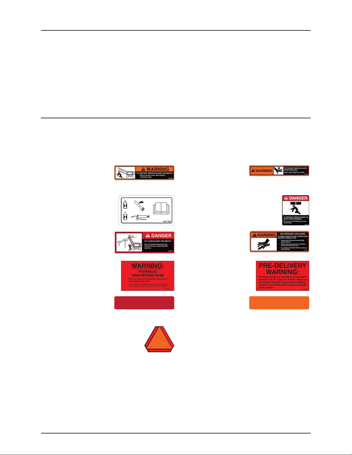
Label explanation
The labels designate potential dangerous places on the machine. Anybody working with or being in close range of the
sprayer must respect these labels!
The labels should always be clean and readable! Worn or damaged labels must be replaced with new ones. Contact your
local dealer for new labels.
10532803 - Fold wings
Keep away when folding,
unfolding wings.
97617903 - Breakaway
See Boom Operator’s manual
for maintenance.
10533003 - Overhead lines
Do not contact electrical lines
when moving or operating!
97610103 - Tank return hose
Tank return hose must be
connected to a low pressure
port.
10533803 - Red Reflector 10533903 - Amber Reflector
10601403 - SMV Sign
Slow moving vehicle
10532703 - Crush fingers
Never place fingers in clutch.
10616103 - Paralift
Risk of serious injury or death from crushing.
Do not enter between tank and center frame.
10532503 - Hydraulic hazard
Risk of serious injury or death
from escaping hydraulic fluid.
97606603 - Pre-Delivery
Remove tie straps before
unfolding boom first time.
8

2 - Safety notes
Local poison information center
If you live anywhere in the United States, the following toll free number will connect you to your Local Poison
€
Information Center.
PHONE NO. 1 - 800 - 222 - 1222
If you live outside the United States, find the number for the poison control center in your phone book and write it
€
in the space below:
PHONE NO._______ - _______ - __________
Keep a list, in the space provided below, of all the chemicals that you have in use.
€
1. _______________________________________________________________________________________________
2. _______________________________________________________________________________________________
3. _______________________________________________________________________________________________
4. _______________________________________________________________________________________________
5. _______________________________________________________________________________________________
6. _______________________________________________________________________________________________
7. _______________________________________________________________________________________________
8. _______________________________________________________________________________________________
9. _______________________________________________________________________________________________
10. ______________________________________________________________________________________________
9

2 - Safety notes
10
3 - Description
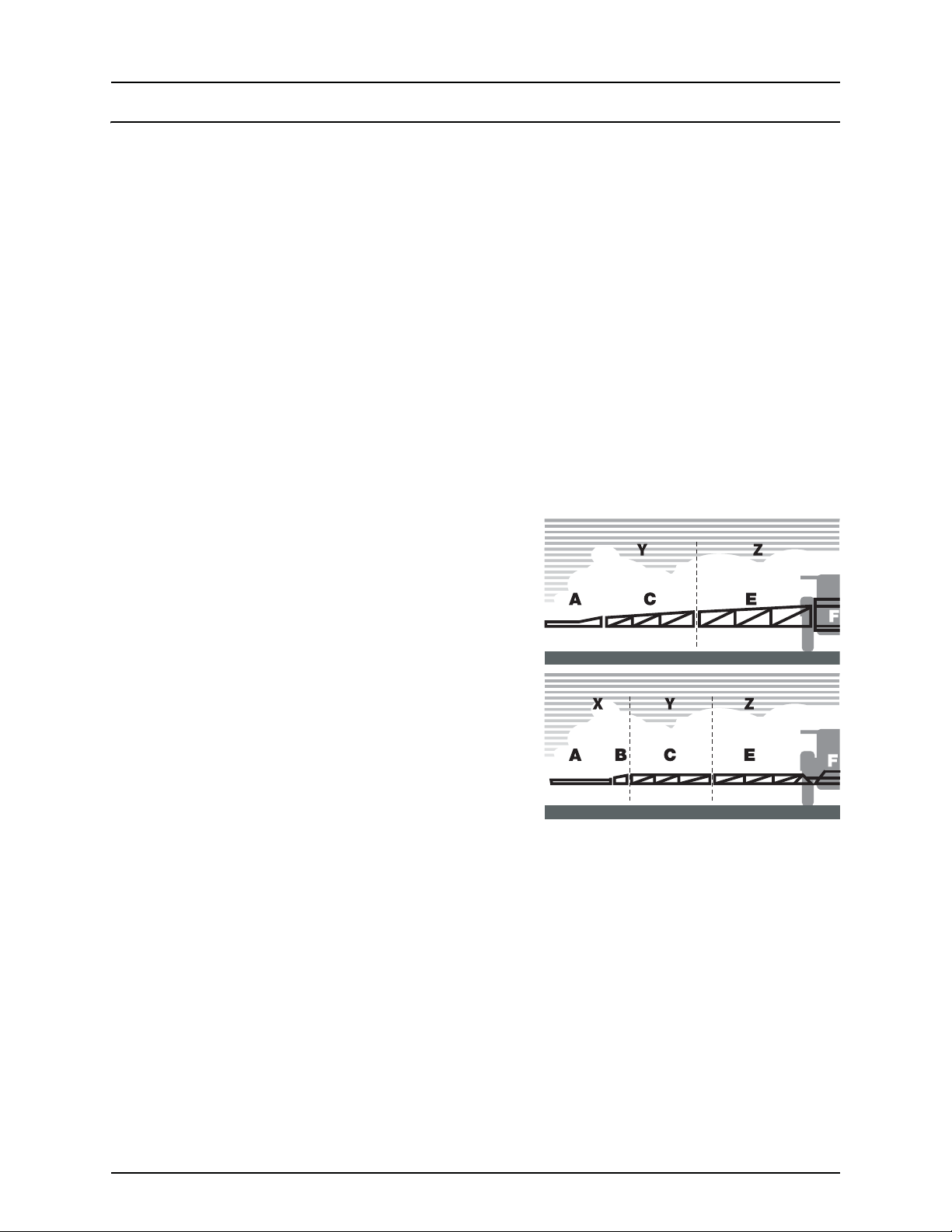
Boom
Boom configurations
The DELTA FORCE boom is trapeze suspended and fully hydraulically operated with all functions controlled via the Direct
Hydraulic System (D.H.).
The DELTA FORCE boom is suspended from a trapeze with nitrogen dampers and is available in 88’, 90’, 100’, 120’ and132’
(26.8, 27.4, 30.5, 36.6, 40.2 m) working widths. The 88’ - 100’ booms have bi-fold wings, while the 120’ - 132’ booms have trifold wings.
Boom features:
• Outer most sections incorporate spring-loaded breakaway.
• Individual boom tilt control.
• Partial folding of outer sections. This enables alternative boom widths.
Full working width Outer sections folded 1st & 2nd outer sections folded
88’ (26.8 m) 50’ (17.7 m) -
90’ (27.4 m) 50’ (17.7 m) -
100’ (30.5 m) 52’ (17.7 m) -
120’ (36.6 m) 90’ (28 m) 52’ (17.7 m)
132’ (40.2 m) 90’ (28 m) 52’ (17.7 m)
For bi-fold booms, the terminology is as follows:
A. Breakaway section
C. Outer section
E. Inner section
F. Center section
For tri-fold booms, the terminology is as follows:
A. Breakaway section
B. Second outer section
C. First outer section
E. Inner section
F. Center section
Note: When controlling the boom, the folding sections are:
÷
X. Second outer section (tri-fold booms only)
Y. First outer section
Z. Inner section
11
3 - Description
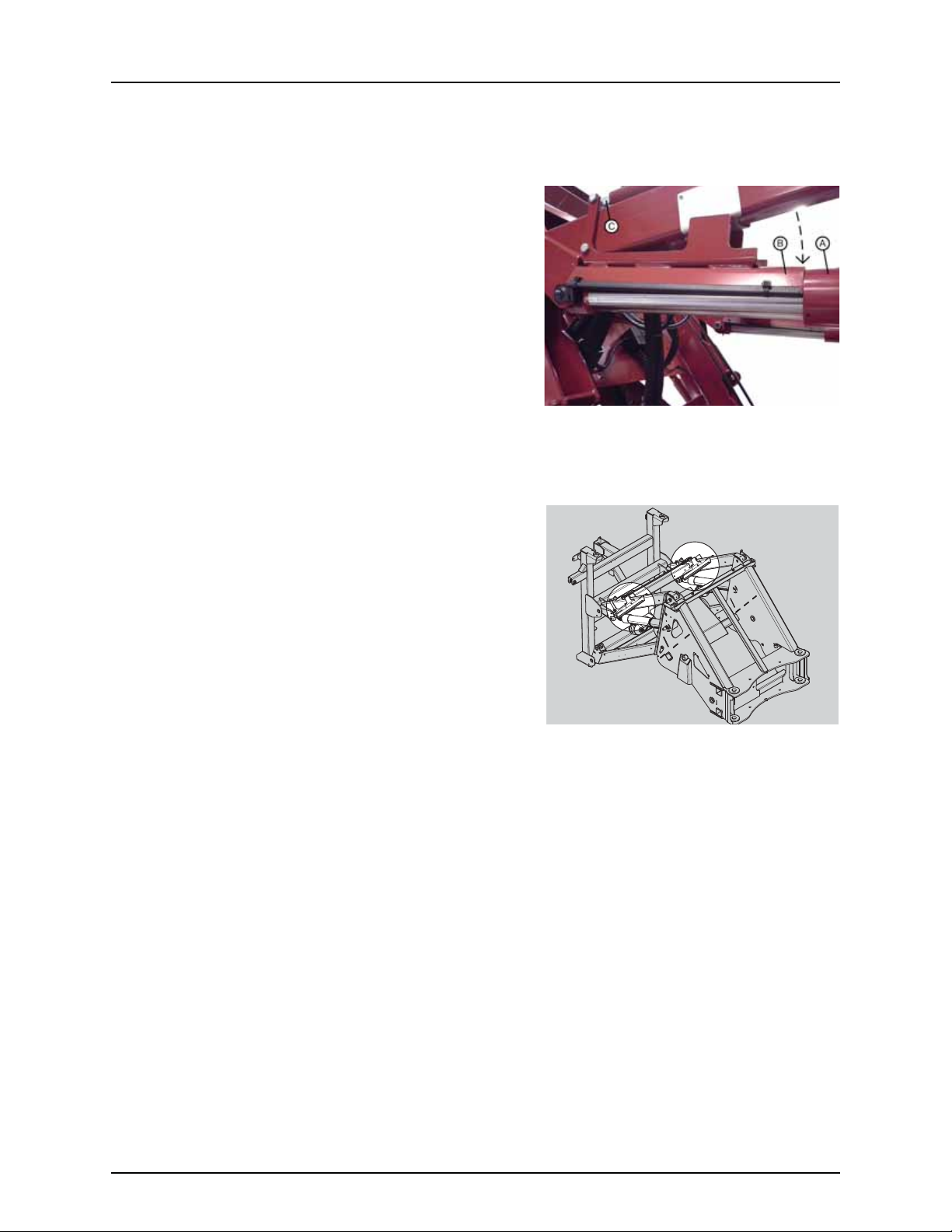
Paralift Lock Brackets
With the spray boom folded in transport position, the paralift is locked in position. This is to prevent accidental movements
of the boom while driving on the road.
Description of the lock mechanism
The hydraulic cylinder (A) for the paralift extends fully to raise the boom
into transport position.
A lock bracket (B) will then automatically be lowered onto the extended
piston rod by means of another hydraulic cylinder (C), when the boom
is fully folded.
the lock bracket will now prevent the piston rod from retracting
unintentionally during road transport, if the hydraulic pressure drops.
The lock bracket helps to ensure a safe transport position of the boom.
WARNING! During road transport, it is important that the lock
±
bracket is in the lock position. If not, it could cause a dangerous
situation, if the hydraulic pressure drops. Risk of the boom gliding
out of the transport brackets, resulting in damage to the mudguards for the wheels and further damage to the
sprayer. The extent of the damage depends on the sprayer size and boom size; however this damage is depending
on other components failing as well.
Service Situation
DANGER! In a service situation, it is very important that the lock
€
bracket (B) is in the lock position. If the hydraulic pressure drops,
when you are standing below the paralift, it could cause a
dangerous situation, as the paralift will be lowered quickly. Risk of
squeezing and getting trapped. Risk of fatal accidents.
12
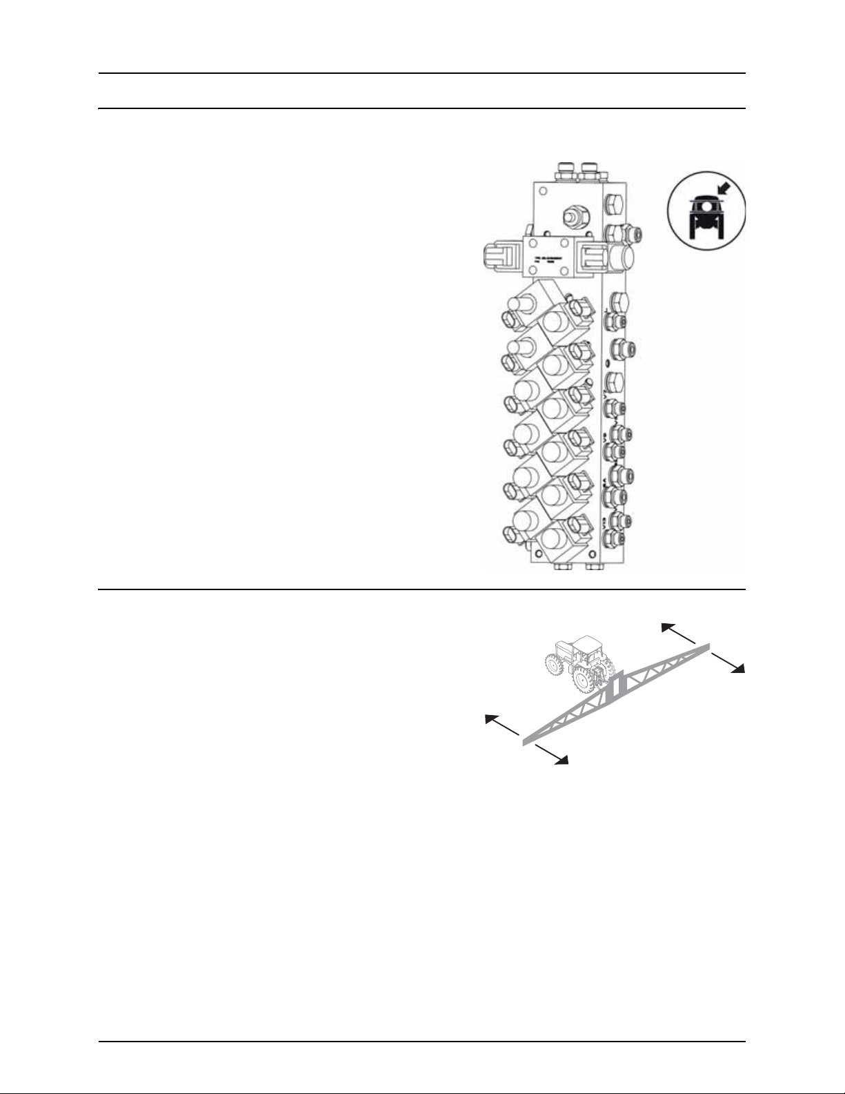
Hydraulics
Hydraulic Block
Spray Boom
The main hydraulic block manages hydraulic pressure for the boom
controls.
3 - Description
Yaw D am pin g
The unfolded spray boom will create yaw movements when:
• driving over uneven terrain
• turning on headland
• speeding up
• braking.
There are 2 types of damping:
• Mechanical
• Hydraulic
Damping Function (Mechanical Yaw)
Rubber blocks located on the hinge assembly provide damping when
the boom makes a yaw movement.
Damping Function (Hydraulic Yaw)
The three accumulators located in the boom center act as dampers for
the yaw movements, when driving in the field. Each accumulator contains nitrogen gas and hydraulic oil, separated by a
diaphragm. When the boom makes a yaw movement, hydraulic oil will be transferred into the accumulator. The oil pushes
the diaphragm while compressing the gas. When this compression overcomes the oil pressure from the boom, the boom
wing is moved back to its original position dampened by the oil flow in the circuit.
13

3 - Description
Hydraulic Block for Yaw
Item Port on hydraulic block
Hydraulic hoses for accumulators ACC1, ACC2, ACC3
Test sockets for accumulators MACC1, MACC2, MACC3, TM
Yaw cylinders on spray boom C1, C2, C3
Return oil back to tractor T
NOTE! For more details, see the hydraulic diagram in the section
“Technical Specifications” in this book.
Boom hydraulic controls on the SetBox (Trailed models)
The boom hydraulic controls on the SetBox control the pendulum lock,
boom folding and stability functions. The buttons on the SetBox control
the following functions:
1. Power ON/OFF.
2. Center unlock.
3. Center lock.
4. Inner wing fold.
5. Inner wing unfold.
6. First outer wing fold.
7. First outer wing unfold.
8. Second outer wing fold.
9. Second outer wing unfold.
14. Not used with Delta Force.
15. Not used with Delta Force.
17. HeadlandAssist automatic.
18. HeadlandAssist boom manual lift to preset height.
Boom hydraulic controls on the instrument panel (Self-propelled models)
The boom hydraulic controls on the instrument panel work in combination with the Grip controls. The buttons on the
console control the following functions:
1. Unfold/Fold second outer section (120’-132’ Tri-fold booms only).
2. Unfold/Fold first outer section.
3. Unfold/Fold Inner section.
4. Center lock.
2
4
1
3
14
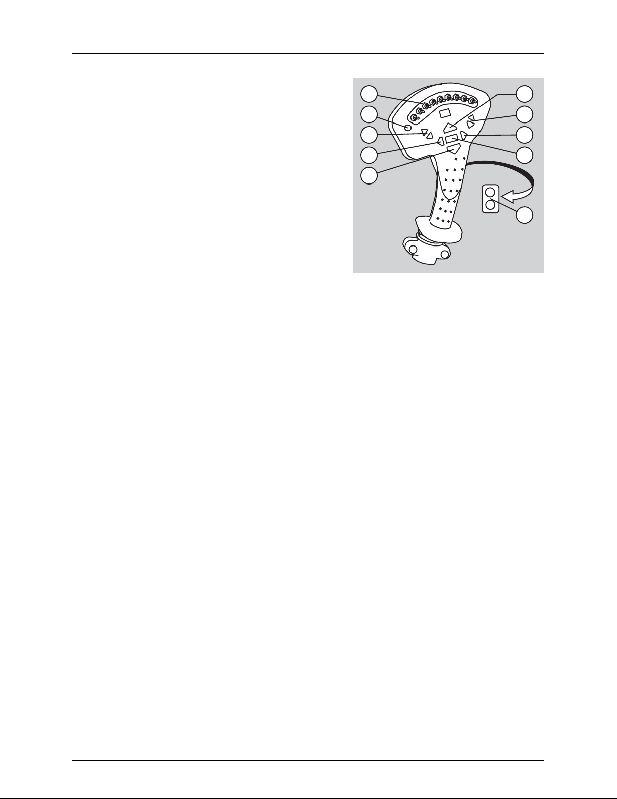
Boom controls on the Grip handle
A. Status LED.
B. Boom section controls.
C. Main ON/OFF.
D. Tilt.
E. Boom height.
F. Not used with Delta Force.
G. Not used with Delta Force.
3 - Description
B
A
D
F
E
E
D
F
C
G
15

3 - Description
16

4 - Sprayer setup
Hydraulic systems
General info
Ensure that the quick couplers are clean before connection!
After having operated the boom and the system has been filled with oil, check the vehicle’s hydraulic oil level and top off, if
necessary.
DANGER! Test of the hydraulic system should be done very cautiously. There may be air trapped in the system which
€
can cause violent movements of the boom.
DANGER! Hydraulic leaks: Never use your fingers to locate a leakage in any part of the hydraulic system. Due to high
€
pressure, hydraulic oil may penetrate the skin.
Requirements - tractor (DELTA FORCE model)
The hydraulic system requires:
• One double-acting outlet for the electro-hydraulic operation of the boom functions. The hydraulic hoses are marked
with arrows and colored tie straps to indicate direction of oil flow. Red tie strap = pressure. Green tie strap = Return to
tank. The hoses must be hooked up to the correct outlet for the hydraulics to function properly (pressure hose to
pressure outlet, return hose to tank outlet).
• Oil flow between 4 - 21 gal/min. (15 - 80 l/min) and a min. pressure of 2610 psi (180 bar).
• Maximum permissible oil pressure is 3050 psi (210 bar).
• Return flow of the connected tractor must be maximum 215 psi (15 bar).
• For Load Sensing systems an oil flow of approximately 0.8 gal/min (3 l/min) at 360 psi (25 bar) is supplied by the sprayer
hydraulics.
17

4 - Sprayer setup
18

5 - Operation
Boom
Safety info
The boom must not be folded/unfolded while driving! Never use the folding/unfolding functions before the sprayer has
been stopped! Failure to do so will damage the boom.
DANGER! Before unfolding the boom it is important to connect trailed sprayers to the tractor to prevent overturning
€
the sprayer.
DANGER! When folding or unfolding the boom, make sure that no persons or objects are within the operating area
€
of the boom.
DANGER! Always follow the guidelines listed below when driving in areas with overhead power lines:
€
• Never use the folding/unfolding functions in areas with overhead
power lines.
• Unintended boom movements may cause contact with overhead
power lines.
ATTENTION! Only unfold and fold the boom on level ground.
19

5 - Operation
Maneuvering of the boom - DELTA FORCE
Applicable for HC 8600 / HC 9600 / ISOBUS.
WARNING! Boom folding is not possible if the center is unlocked. A manual override of the center lock is possible by
±
activating switches 2 or 3 on the SetBox or switch 4 on the self-propelled instrument panel.
WARNING! Only operate the folding functions when the sprayer is stationary! Failure to do so may damage the boom.
±
ATTENTION! If a folding sequence is not completed, a warning message on the Hardi® display will ask you to complete
this sequence before starting next sequence.
ATTENTION! Only buttons relevant for boom functions are mentioned here.
To unfold the boom using the SetBox & Grip controls (Trailed models)
1. Press the boom lift button (H) to lift the boom clear of the transport
brackets.
2. Press and hold (A) and (C) to tilt boom wings up, if needed.
3. Check that the center locked symbol is visible in the display. If
not, press button (3) to engage the center lock. Press and hold
button (5) to unfold the inner sections completely (approximately
5 sec. or a warning will appear).
4. Press and hold (B) and (D) to tilt boom wings down until level.
5. Press and hold button (7) to unfold the 1st outer sections.
6. Press and hold button (9) to unfold the 2nd outer sections (120’-
132’ tri-fold booms only).
7. Press and hold the boom down button (I) to lower the boom to the
correct working height.
8. Press button (2) and symbol appears in display when the
center is unlocked.
A
B
E
I
H
C
D
F
G
To fold the boom using the SetBox & Grip controls (Trailed models)
1. Press the boom lift button (H) to raise the boom to the highest
possible position.
2. Press button (3) to engage the center lock. The symbol appears
in display when center is locked.
3. Press and hold button (8) to fold the 2nd outer sections (120’-132’
tri-fold booms only).
4. Press and hold button (6) to fold the 1st outer sections. Check that
the center lock symbol is visible in the display.
5. Press and hold (A) and (C) to tilt boom wings up until they reach the alignment indicators.
6. Press and hold button (4) to fold the inner sections.
7. Press the boom down button (I) to lower the boom until it rests in the transport locks.
Press and hold (B) and (D) to tilt boom wings down into the transport rests if necessary.
÷
20

5 - Operation
To unfold the boom using the Instrument panel & Grip controls (Self-propelled models)
1. Press the boom lift button (H) to lift the boom clear of the transport
brackets.
2. Check that the center locked symbol is visible in the display. If
not, press the bottom of button (4) to engage the center lock. Press
and hold the top of button (3) to unfold the inner sections
completely (approximately 5 sec. or a warning will appear).
3. Press and hold (B) and (D) to tilt boom wings down until level.
4. Press and hold top of button (2) to unfold the 1st outer sections.
5. Press and hold top of button (1) to unfold the 2nd outer sections
(120’-132’ tri-fold booms only).
6. Press and hold the boom down button (I) to lower the boom to
the correct working height.
7. Press the top of button (4) and the symbol appears in display
when the center is unlocked.
WARNING! The boom must be unlocked before engaging
±
AutoTerrain system.
To fold the boom using the Instrument panel & Grip controls (Selfpropelled models)
1. Press the boom lift button (H) to raise the boom to the highest
possible position.
2. Press the bottom of button (4) to engage the center lock. The
symbol appears in display when center is locked.
3. Press and hold bottom of button (1) to fold the 2nd outer sections
of tri-fold booms (6 seconds) or outer sections of bi-fold booms (4
seconds).
4. Press and hold bottom of button (2) to fold the 1st outer sections of tri-fold booms (6 seconds). Check that the center
lock symbol is visible in the display. If not locked, then press the bottom of button (4) until the center is locked.
5. Press and hold buttons (A) and (C) to tilt boom wings up until they reach the alignment indicators.
6. Press and hold bottom of button (3) to fold the inner sections.
7. Press the boom down button (I) to lower the boom until it rests in the transport locks.
A
B
E
I
2
4
1
3
H
C
D
F
G
NOTE! Press and hold (B) and (D) to tilt boom wings down into the transport rests if necessary.
÷
21

5 - Operation
22

A
6 - Maintenance
Lubrication
General info
Always store lubricants clean, dry and cool - preferably at a constant temperature - to avoid contamination from dirt and
condensed water. Keep oil filling jugs, hoppers and grease guns clean, and clean the lubricating points thoroughly before
lubricating. Avoid prolonged skin contact with oil products.
Always follow the quality and quantity recommendations. If no quantity is recommended, lubricate until new grease
becomes visible.
Pictograms in lubrication & oiling plans indicate the following:
1. Lubricant to be used (see “Recommended lubricants” below).
2. Recommended intervals. Shown in hours or with a symbol for
occasional maintenance.
3. Amount to be used. Only shown if an amount is specified.
ATTENTION! If the sprayer is cleaned with a high pressure cleaner,
lubrication of the entire machine is recommended.
Recommended lubricants
BALL BEARINGS:
Universal Lithium grease, NLGI No. 2
CHEVRON Multifak EP 2
SHELL RETINAX EP2
CASTROL LMX GREASE
SLIDE BEARINGS:
Lithium grease with
Molybdenumdisulphide or graphite
SHELL RETINAX HDM2
CASTROL MOLYMAX
OIL LUB. POINTS:
TOTAL Transmission TMSAE 80W/90
Castrol EPX 80W/90
SHELL Spirax 80W/90
Mobil Mobilube 80W/90
Grease Nipple
When lubricating the sprayer, please use a grease gun which fits the
dimensions of the grease nipple.
Nipple head type: DIN 71412
Nipple head size (A): 6.5 mm
ATTENTION! If grease is leaking from the nipple near its threaded
part when grease is being applied, please tighten the nipple by
using a wrench or socket. Replace the nipple if it is damaged or
bent out of shape.
ATTENTION! If applying grease into the nipple seems difficult,
unscrew the nipple. Check if the nipple is blocked inside, or if the
spring-loaded ball is stuck. Clean or replace as needed.
23

6 - Maintenance
Grease Gun Calibration
Before lubricating the sprayer, you must calibrate your grease gun to ensure that the correct amount of grease is applied to
each lubrication point. The correct amount of grease applied will prolong the lifetime of the sprayer.
Calibration Example
1. Insert the correct grease cartridge in your grease gun.
2. Apply grease onto a tissue or a piece of paper. Complete 10 full
strokes of the grease gun.
3. Place the paper with grease on a scale (A).
4. If your grease pile weighs for example 10 grams, then 1 stroke
equals 1 gram of grease.
When calibrated, you can count how many strokes to complete, when
lubricating the different grease points on the sprayer according to the
specifications.
Alternative Method
1. Count the strokes, until you have 10 grams of grease piled up on
the scale (A).
2. Now you can figure out how many strokes to use for applying a
certain amount of grease to a lubrication point.
24

Boom lubrication and oiling plan - trapeze boom center
-
8
10
1
1
6 - Maintenance
2
8
7
Close-up of Grease Nipples
6
4
5
3
25

6 - Maintenance
1
2
4
3
5
7
6
-
10
1
7
-
8
11
C-500
Boom Wings
Both boom wings, left and right, are to be lubricated equally.
8
10
11
9
Close-up of Grease Nipples
26

6 - Maintenance
Service and maintenance intervals
10 hours service - Lubricate boom and center
Some lubrication points on the boom and center parts need extra attention when using the AutoTerrain system. These
lubrication points, marked “10h” in “Boom lubrication and oiling plan - trapeze boom center” on page 25, need attention
every 10 working hours to work correctly.
100 Hours Service - Retightening the Spray Boom
Due to several movements of the spray boom from driving in the field with an unfolded boom, you must retighten all bolted
connections on the boom center and boom wings.
Where you find bolts with Nord-Lock washers, please tighten with the
following torques.
Bolt size Torque - Ft/lb (Nm)
M10 37 (50)
M12 63 (85)
M14 100 (136)
M16 153 (208)
M18 215 (291)
M20 301 (408)
M22 411 (557)
M24 519 (703)
M27 758 (1028)
M30 1033 (1401)
250 hours service - Readjustment of the boom
See section “Readjustment of Boom - General Info” on page 29.
27

6 - Maintenance
Occasional maintenance
General info
The maintenance and replacement intervals for the following will depend very much on the conditions under which the
sprayer will be operated and are therefore impossible to specify.
Feed pipe snap-lock assembly
Disassembly
1. Screw the union nut (A) completely off.
2. Pull the feed piping and hose barb apart.
3. Take out the O-ring (B).
4. Inspect and oil O-ring (B). Change the O-ring (B) if worn, before
reassembly.
Reassembly
1. Check that the barbed lock ring (C) is fitted to the feed pipe with
barb pointing away from pipe opening.
2. Fit the oiled O-ring (B) on top of the lock ring (C).
3. Push the feed pipe and hose barb together.
4. Screw the union nut (A) on the hose barb and tighten union nut
(A) by hand.
Initial fitting of fittings
ATTENTION! This method can only be used for pipes not fitted
into pipe clamps.
1. Fit the barbed lock ring (C) to the feed pipe with barb pointing
away from pipe opening.
2. Fit the oiled O-ring (B) on top of the lock ring.
3. Screw the union nut (A) partly on the hose barb.
4. Press the feed pipe and hose barb together.
5. Tighten the union nut (A) by hand.
Feed pipe clamp assembly
A feed pipe can be removed from the pipe clamps the following way:
1. Use a flat bladed screwdriver to pry the cover off the first corner (A).
2. Hold the clamp top with your hand and pr y off the opposite corner
(B) with the screwdriver.
3. Pry off the other side of the pipe clamp with the screwdriver.
4. Take out the feed pipe.
28

6 - Maintenance
Readjustment of Boom - General Info
Before starting adjustment jobs, please go through this check list.
1. The sprayer must be well lubricated (see the section “Lubrication”).
2. Connect the sprayer to the tractor.
3. Place tractor and sprayer on level and solid ground.
4. Activate parking brakes for tractor.
5. Put wedges under the wheels to prevent rolling.
6. Unfold the boom.
7. Place strong supports below the center section and all boom sections to relieve the load from the hydraulic cylinders.
If you have a lifting crane, support the center section as a minimum, as this is the heaviest boom part (up to
2205lbs/1000 kg).
DANGER! No one is allowed under the boom, while the adjustment is carried out.
±
DANGER! Adjustment of hydraulic cylinders is to be carried out without pressure in the system.
±
ATTENTION! For information on boom terminology, see “Boom configurations” on page 11.
ATTENTION! To check the boom alignment, you can use a spirit level, or you can measure the distance to the ground
from similar points in both ends of the boom wing (this method is used for horizontal alignment and only on level
ground). When using the latter method, both distances should be equal to obtain a horizontal boom.
ATTENTION! Boom sections, which are not supported during adjustment jobs, might fall down or be difficult to adjust.
ATTENTION! Adjustments are to be completed equally for both right and left boom wings.
ATTENTION! The following types of arrows are used when describing the different boom adjustments:
Point of adjustment Boom is adjusted upwards Boom is adjusted downwards Boom is adjusted away from you Boom is adjusted towards you
29

6 - Maintenance
Adjustment of Boom Tilt
The unfolded spray boom must be horizontal to begin with, before you start a spray job. If needed, horizontal adjustment
of the boom wings is possible by adjusting the ram eye on the hydraulic tilt cylinders located on both sides of the sprayer.
NOTE! This boom can tilt down to max. 4 degrees below horizontal level (only if the AutoHeight function is installed).
÷
Steps for adjustment:
ATTENTION! If the hydraulic cylinder is not being replaced, it is not necessary to disconnect the ram eye / hydraulic
cylinder from the boom to make the adjustments described in the following steps. Instead, the piston rod can be
rotated by turning it with a wrench placed just behind the ram eye, without disconnecting the hydraulic cylinder
from the boom.
1. Disconnect the ram eye from the boom wing.
2. Loosen nut (A) and the pin bolt inside. This will unlock the ram eye
from the cylinder’s piston rod.
3. Rotate the cylinder rod with a wrench fitted on the flat surfaces on
the end of the ram eye (near A). This will move the ram eye in or
out.
To raise the boom wing: Move the ram eye inwards.
To lower the boom wing: Move the ram eye outwards.
4. To be able to lock the ram eye to the piston rod after adjustment,
turn the ram eye 1 full revolution at a time; this will move the ram
eye approximately 1/16” (2 mm) in or out.
5. Reconnect the ram eye to the boom parts to check the horizontal
level of the boom wing.
If further adjustment is needed, go back to step 3.
If horizontal alignment is OK, tighten the pin bolt and nut (A).
Adjustment is now completed.
30

6 - Maintenance
B
C
E
D
Horizontal Alignment of Inner Sections (Hydraulic Yaw)
This alignment is to compensate for the wind resistance when driving with an unfolded boom, as well as keeping a good
balance in the boom when driving on uneven fields. The boom is adjusted relatively to the direction of driving.
Steps for adjustment:
1. Turn the stop bolt (A). Wrench = 30 mm.
• To bring the boom forward (B):
Turn the stop bolt counterclockwise and tighten the jam nut.
Torque = 185 Ft/lb (250 Nm).
• To bring the boom backward (C):
Loosen the jam nut and turn the stop bolt clockwise.
2. .Stand near the boom center and look towards the boom end.
Compared to being on a perpendicular line to the direction of
driving, the boom should now be adjusted a little forward (B).
The boom tip must be between 4” (100 mm) and 18” (450 mm)
ahead of the perpendicular line.
Hydraulic Yaw
3. When the plunger cylinder (D) is fully pressurized, the piston stroke
(E) must not exceed 1.5” (38 mm). Adjust the stop bolt (A)
accordingly.
4. Adjustment is completed when the boom is aligned within the
range mentioned in step 2. After aligning other boom sections,
check if realigning is needed here.
31

6 - Maintenance
Accumulator Service
If the yaw damping seems to be insufficient, the accumulators need to
be recharged or replaced. Ask your HARDI® dealer to assist you.
1. Check for any leaks.
2. Check pressure setting for the accumulators in the test sockets,
which are located in the hydraulic block below. Hydraulic hoses for
the accumulators are also connected to this block.
3. Fill nitrogen gas (N
pressure of 260 psi (18 bar) [factory setting]. The gas volume in the
accumulator is approx. 0.5 quarts/liters.
4. Fill hydraulic oil until you reach a pressure of 500 psi (35 bar) in the
accumulators [factory setting].
DANGER! Do not fill the accumulators with other gases, such as air or
pure oxygen. Risk of explosion.
) into the accumulators, until you reach a
2
32

6 - Maintenance
B
C
Horizontal Alignment of Inner Sections (Mechanical Yaw)
This alignment is to compensate for the wind resistance when driving with an unfolded boom, as well as keeping a good
balance in the boom when driving on uneven fields. The boom is adjusted relatively to the direction of driving.
Steps for adjustment
1. Loosen the 2 allen screws (1) on the link eye
2. Turn the threaded rod (2). Wrench=16mm
• To bring the boom forward (B):
Turn the threaded rod (2) counterclockwise and tighten allen
screws (1).
Torque = 26 Ft/lb (35 Nm)
• To bring the boom backward (C):
Turn the threaded rod (2) clockwise and tighten the allen screws
(1).
Torque = 26 Ft/lb (35 Nm)
ATTENTION! It is necessary to maintain 51/64” (20mm) of threads inside the link eye.
3. Stand near the boom center and look towards the boom end.
Compared to being on a perpendicular line to the direction of
driving, the boom should now be adjusted a little forward (B).
The boom tip must be between 4” (100 mm) and 18” (450 mm)
ahead of the perpendicular line.
33

6 - Maintenance
ATTENTION! The hinge will move forward and backward during
the spray job; make sure that the threaded rod does not come in
contact with the boom. Minimum distance is 5/8” (15mm).
ATTENTION! Make sure that there are threads showing outside of
the jamb nuts. If not you will run the risk of the boom coming free
and swinging forward toward the tractor cab.
Mechanical End Stop
1. The mechanical end stop (1) must be adjusted so that it is placed
in the middle of the folding arm.
• Loosen bolt (A) so that the end stop can slide freely.
• Adjust the position of the end stop by screwing or unscrewing bolt
(B).
• Tighten counter nut (C).
ATTENTION! Make sure that bolt (B) does not come completely
unscrewed from mechanical stop (1).
34

6 - Maintenance
Anti-Yaw Damping
1. Adjusting the damping on the Anti-Yaw is done by tightening or
loosening the tension on either side of the rubber dampers.
• To make the damping tighter:
Loosen jamb nut (A), and tighten tensioner nut (B), making sure to
retighten jamb nut (A).
• To make the damping looser:
Loosen jamb nut (A), and loosen tensioner nut (B), making sure to
retighten jamb nut (A).
ATTENTION! When loosening up the tension on the dampeners, there should always be a tension load on the
dampers. They should never be loose.
NOTE. Factory adjustment is finger tight, then tighten the tensioning nuts another 10mm with a wrench.
÷
35

6 - Maintenance
Vertical Alignment of Middle and Outer Sections
Steps for adjustment:
1. Start with the middle section, which is aligned with the inner
section.
2. At the top of the boom, nuts (A, B) are adjusted. Wrench = 41 mm.
Raise the boom: Loosen (A), tighten (B).
Lower the boom: Loosen (B), tighten (A).
3. At the bottom of the boom, the ram eye (C) can be adjusted if
needed. Remove the black pin (D), loosen the jam nut (E) and turn
the ram eye 180°. Replace the black pin and check alignment of the
boom section.
4. When the middle section is aligned, tighten all jam nuts.
Adjustment is completed when the alignment is straight, and the
folding is trouble-free.
5. The outer section is aligned with the middle section in the same
way by completing steps 2 & 4.
36

Adjustment of Boom Lock
Description of Boom Lock Mechanism
To prevent accidental folding of the spray boom while spraying, the
boom joints interlock automatically when fully unfolded. The conical
bolt (A) will guide the boom sections into the interlocking position.
A specially designed steel plate (B) will be lifted up, as the conical bolt
(A) passes through the plate. The plate (B) will fall down behind the bolt
head, thus securing the unfolded position.
When folding, a hydraulic cylinder (C) will temporarily pull up the steel
plate (B) to allow the boom sections to separate.
NOTE! On the picture, the cylinder (C) is detached from the steel
÷
plate (B). It must be attached during operation of the boom.
Horizontal Alignment of the Boom
The bolt (A) can be adjusted sideways as needed.
1. Loosen the lock nut (D). Wrench = 41 mm.
2. Turn lock bolt (A), until the boom sections align. Wrench = 46 mm.
6 - Maintenance
ATTENTION! The lock bolt is eccentric. Always turn it 1 full
revolution at a time; this will move the lock bolt 1/8” (3 mm) back
or forth. Ensure that the lock bolt aligns with the center of the
hole in the lock mechanism when the adjustment is completed.
3. Retighten the lock nut (D). Torque = 185 Ft/lb (250 Nm).
Adjustment completed.
Vertical Alignment of Breakaway Section
Align the breakaway with the outer section of the boom.
Steps for adjustment:
1. Loosen nut (A). Wrench = 24 mm.
2. Rotate turnbuckle (B). Wrench = 17 mm.
Turn clockwise: The breakaway is raised.
Turn counterclockwise: The breakaway is lowered.
3. When the breakaway is aligned, tighten nut (A)
Adjustment is completed.
37

6 - Maintenance
Horizontal Alignment of Breakaway Section
Complete the following steps to adjust the breakaway to align it with the outer section of the boom.
ATTENTION! Before making adjustments, Locktite 638 (or
equivalent) must be added between the bolt holes on bracket (B)
to ensure that the bracket (B) does not move after adjustment.
1. There are four sets of bolts and nuts (A) in all, mounted in both
sides of the steel bracket (B). Wrench = 17 mm.
In the picture, the bolt and nut are already removed from one hole.
The slotted holes in the steel bracket allow adjustment. The steel
bracket is attached to the breakaway
2. Align the breakaway with the outer section by moving the bracket.
3. Retighten the bolt and nuts. Torque = 130 Ft/lb (180 Nm).
Adjustment is completed.
38

6 - Maintenance
Adjustment of Breakaway Section
Th e br eakaw ay se ctio n at t he b oom e nd wi ll mo ve b ack o r for th if it hi ts a stat iona ry obj ect ( e.g . a po le o r a tr ee) when driv ing
with an unfolded spray boom. The spring on the outer section of the boom will pull the breakaway back into place when
the boom is clear of the object. When spraying, the breakaway may also sway a little if driving on uneven ground.
The spring is preloaded from the factory - but adjustment is needed if:
• the breakaway is continuously swaying a lot due to a bumpy field (tighten the spring).
• the breakaway has become very hard to move by hand, when the sprayer is at a standstill (loosen the spring).
• reattachment is necessary due to replacement of the spring, cable or other parts.
Steps for adjustment:
A. Turn these nuts to adjust the spring.
B. Dimension of preload of the spring. Factory setting is 18-7/8” (480 mm). Maximum preload is 21-5/8” (550 mm).
WARNING! Risk of squeezing. Keep fingers and clothes away from the spring windings when adjusting the spring.
39

6 - Maintenance
Alignment of Rubber Pads on Spray Boom
When the boom is folded, it must be checked that it rests correctly on the rubber pads. The rubber pads protect the boom
parts during folding and transport, so please check them for misalignment. The rubber pads also help to steer the boom
into the transport position.
Steps for adjustment:
1. Fold the boom and check the positions of the rubber pads (A).
They must be touching, when folding is completed.
2. If realignment is needed, loosen the four lock nuts (B) slightly.
Wrench = 17 mm.
3. Move steel bracket with the rubber pad sideways to the wanted
position.
4. Tighten the four lock nuts to lock the position of the rubber pad.
5. Adjust other rubber pads on the boom as needed.
40

6 - Maintenance
Adjustment of Tilt Indicators
When tilting the spray boom for transport, there are indicators to ensure the correct height of the tilts. When correctly
adjusted, the indicators will point to the very end of the tilt cylinder barrel so the entire spray boom can be set directly into
transport after folding.
Steps for adjustment:
1. Fold the boom completely into transport.
2. Without activating the tilts, lift the spray boom via the main lift, unfold the inner fold and check that indicator (B) is
pointed at the end of the tilt cylinder barrel.
3. If not then it is necessary to loosen bolts (A) and reposition indicator (B) so that it is pointed at the end of the tilt cylinder
barrel.
41

6 - Maintenance
A
A
B
B
A
B
Venting the Boom Hydraulics
If the hydraulic cylinders or hoses have been dismantled, it is necessary to vent the cylinders after reassembly.
DANGER! Failing to vent the hydraulic system when needed may result in violent boom movements and poor boom
€
performance. Risk of damage to the boom parts or foreign objects nearby. Risk of severe injuries or death.
ATTENTION! Not all hydraulic cylinders have a venting option. In this case you must loosen the hydraulic hose
connected to the cylinder to let the air out this way. Note that ORFS fittings are used - be careful not to damage the
sealing O-ring, when venting oil.
ATTENTION! The following venting instructions are for double acting cylinders only. For single acting cylinders, such
as for the boom tilt motion, the venting is easily completed: After service, apply hydraulic pressure to the cylinder,
retract and extend the piston approx. 5 times, and the air is then removed from the system automatically.
Sequence of Cylinders for Venting
To complete an efficient venting of air in the system, this sequence should be followed.
1. Boom center: Cylinders for inner sections on boom wings.
2. Boom wings: Cylinders for middle sections.
3. Boom wings: Cylinders for outer sections.
4. Boom center: Cylinder for slant motion.
Venting Procedure
Follow these steps to complete the venting. Both venting screws or valves (A and B) are closed to begin with.
1. Cylinder piston is retracted.
2. Remove the dust caps from the venting valves.
3. Mount a clear 5 mm hose to the venting valve (A) and lead it into
a suitable container.
4. Open the venting valve (A).
5. Activate the hydraulic oil pressure and extend the piston fully.
6. Close the venting valve (A) and remove the hose.
7. Mount the clear hose to the other venting valve (B).
8. Open the venting valve (B).
9. Activate the hydraulic oil pressure and retract the piston fully.
10. Close the venting valve (B) and remove the hose.
11. Repeat steps 3 - 10 a few times until air is no longer visible in the
hose.
12. Refit the dust caps. Venting is completed for this cylinder.
13. Check your hydraulic oil level - top up if needed.
DANGER! Be careful when operating the cylinders. Make sure that no unauthorized persons are in the working area,
€
when folding or unfolding the boom! When retracting the pistons into the cylinders, keep fingers, tools and clothes
away from the piston. Risk of getting trapped between moving boom parts or folded boom sections resulting in
severe injuries or death.
ATTENTION! Depending on the boom design, it might be more practical to begin with the cylinder extended.
ATTENTION! A helping hand is useful to complete the venting procedure.
42

Operational problems
General info
Operational incidents are frequently due to the same reasons:
1. Rusted or dirty hydraulic components cause bad connections and early wear.
2. A badly charged or faulty battery causes failures and misbehavior in the electrical system.
Therefore ALWAYS check
1. Hydraulic components are clean.
2. The condition of the tractor battery and its connectors are good.
7 - Fault finding
43

7 - Fault finding
Hydraulic system - Z model
FAULT PROBABLE CAUSE CONTROL/REMEDY
No boom movements when activated. Insufficient hydraulic pressure. Check oil pressure.
Check tractor hydraulic oil level.
Insufficient oil supply. Oil flow must be between 4 gpm (15 l/min) and
Blown fuse(s). Check / replace fuse in junction box.
Bad / corroded electrical connections. Check / clean connections, multi plugs etc.
Insufficient power supply. Voltage on activated solenoid valve must be more
Defect relay / diodes in junction box. Check relays, diodes and soldering at PCB in junction
Clogged restrictors in bypass block. Remove and clean restrictors in bypass block (See
Wrong polarity. Check polarity. Red positive (+) Black negative (-).
Boom lift raises to max. position when tractor
hydraulics are engaged.
Oil heats up in Closed Center systems. Bypass valve does not close properly. Check / close (screw in) by-pass valve.
Individual ram does not move. Clogged restrictor. Dismantle and clean restrictor.
Wrong oil inlet to bypass block. Connect hydraulic snap couplers opposite in tractor
Back pressure in return line exceeds 290 psi. Connect the return line with free flow to hydraulic oil
Internal leaks in flow regulator. Replace flow regulator O-rings and backup rings.
21 gpm (80 l/min).
Check tractor hydraulic oil level.
than 8 volts.
Use wires at least 10 awg. (4.0 mm²) for power supply.
box. LED diodes indicate boom functions.
hydraulic diagram). Change hydraulic oil + filter.
outlets, or engage spool valve lever in opposite
direction.
reser voir.
Divide return line in two and lead return oil back to
reservoir via two spool valves.
Replace flow regulator.
NOTE. Other manuals supplied with your sprayer may contain more information.
÷
44

Diagrams
Boom Hydraulics, 2-Fold Boom
Mechanical Yaw
8 - Technical specifications
45

8 - Technical specifications
Hydraulic Yaw
46

Mechanical Yaw with Norac
8 - Technical specifications
47

8 - Technical specifications
Hydraulic Yaw with Norac
p
48

Boom Hydraulics, 3-Fold Boom
Hydraulic Yaw
8 - Technical specifications
49

8 - Technical specifications
Hydraulic Yaw with Norac
50

9 - Warranty
9 - Warranty
Warranty policy and conditions
HARDI® NORTH AMERICA INC. , 1500 West 76th Street, Davenport, Iowa, USA hereinafter called “HARDI®”, offers the following
limited warranty in accordance with the provisions below to each original retail purchaser of its own manufacturer, from an
authorized HARDI® dealer that such equipment is at the time of delivery to such purchaser, free from defects in material and
workmanship and that such equipment will be warranted for a period of one year from the time of delivery to the end user,
providing the machine is used and serviced in accordance with the recommendations in the Operator’s Manual and is
operated under normal farm conditions.
1. This limited warranty is subject to the following exceptions:
a)Parts of the machine not manufactured by HARDI®, (i.e. engines, tires, tubes, electronic controls and other
components or trade accessories, etc.) are not covered by this warranty but are subject to the warranty of the
original manufacturer. Any claim falling into this category will be taken up with the manufacturer concerned.
b)This warranty will be withdrawn if any equipment has been used for purposes other than for which it was intended
or if it has been misused, neglected, or damaged by accident, let out on hire or furnished by a rental agency. Nor
can claims be accepted if parts other than those manufactured by HARDI® have been incorporated in any of our
equipment. Further, HARDI® shall not be responsible for damage in transit or handling by any common carrier and
under no circumstances within or without the warranty period will HARDI® be liable for damages of loss of use, or
damages resulting from delay or any consequential damage.
2. We cannot be held responsible for loss of livestock, loss of crops, loss because of delays in harvesting or any other
expense or loss incurred for labor, supplies, substitute machinery, rental for any other reason, or for injuries either to
the owner or to a third party, nor can we be called upon to be responsible for labor charges, other than originally
agreed, incurred in the removal or replacement of components.
3. The customer will be responsible for and bear the costs of:
a)Normal maintenance such as greasing, maintenance of oil levels, minor adjustments including the boom.
b)Transportation of any HARDI® product to and from where the warranty work is to be performed.
c)Dealer travel time to and from the machine or to deliver and return the machine from the service workshop for
repair unless otherwise dictated by state law.
d)Dealer traveling costs.
4. Parts defined as normal wearing items, (i.e. Pump Diaphragms, Valves, O-rings, Tires and V-belts) are not in any way
covered under this warranty.
5. This warranty will not apply to any product which is altered or modified without the express written permission of
the HARDI® Service and Engineering Departments and/or repaired by anyone other than an Authorized HARDI®
Dealer.
6. Warranty is dependent upon the strict observance by the purchaser of the following provisions:
a)That this warranty may not be assigned or transferred to anyone.
b)That the Warranty Registration Certificate has been correctly completed by dealer and purchaser with their names
and addresses, dated, signed and returned to the appropriate address as given on the Warranty Registration
Certificate within 30 days of delivery to the purchaser.
c)That all safety instructions in the operator’s manual shall be followed and all safety guards regularly inspected and
replaced where necessary.
7. No warranty is given on second-hand products and none is implied.
8. Subject to the following terms, conditions and contributions, HARDI® extends the warranty on polyethylene tanks
(excluding fittings, lids and gaskets
must be drained and flushed with fresh water after each day’s use. HARDI®’s liability is limited to replacement of
defective parts FOB our plant in Davenport, IA at no cost to the purchaser for the first twelve months after date of
purchase; at 20% of the then current retail price during the second year; at 40% during the third year; at 60% during
the fourth year; and at 80% during the fifth year. This extended warranty is subject, in each instance, to the tank being
inspected and approved for replacement or repair by HARDI® personnel before HARDI® will accept any liability
hereunder.
9. Subject to the following terms, conditions and contributions, HARDI® extends the warranty on HARDI® diaphragm
pumps (excluding wearing parts such as diaphragms, valves and o-rings
) to FIVE YEARS on field sprayers. To qualify for this extended warranty, the tank
) to FIVE YEARS. To qualify for this extended
51

9 - Warranty
warranty, the pump must be drained and flushed with fresh water after each day’s use. HARDI®’s liability is limited to
replacement of defective parts, FOB our plant in Davenport, IA at no cost to the to the purchaser during the first
twelve months after date of purchase; at 20% of the then current retail price during the second year; at 40% during
the third year; at 60% during the fourth year; and at 80% during the fifth year. This five year extended warranty is
subject, in each instance, to the pump being inspected and approved for replacement or repair by HARDI® personnel
before HARDI® will accept any liability hereunder.
10. HARDI® reserves the right to incorporate any change in design in its products without obligation to make such
changes on units previously manufactured.
11. The judgement of the HARDI® Service Department in all cases of claims under this warranty shall be final and
conclusive and the purchaser agrees to accept its decisions on all questions as to defect and the repair or exchange
of any part or parts.
12. No employee or representative is authorized to change this warranty in any way or grant any other warranty unless
such change is made in writing and signed by the CEO in the Davenport office. Approval of warranty is the
responsibility of the HARDI® Service Department.
13. Any warranty work performed which will exceed $1000.00 MUST
Department. Warranty claims filed without prior approval will be returned.
14. ANY
15. Claims under this policy MUST be filed with the HARDI® Service Department within thirty (30) days of when the work
16. Parts which are requested for return by the HARDI® Service Department must be returned prepaid within thirty (30)
17. Warranty claims must be COMPLETELY filled out including part numbers and quantities or claims will be returned to
pump replacement MUST be approved by the HARDI® Service Department.
is performed or warranty shall be void unless prior arrangements are made.
days for warranty settlement.
the submitting dealer.
be approved IN ADVANCE by the Service
DISCLAIMER OF FURTHER WARRANTY
THERE ARE NO WARRANTIES, EXPRESSED OR IMPLIED, EXCEPT AS SET FORTH ABOVE. THERE ARE NO WARRANTIES
WHICH EXTEND BEYOND THE DESCRIPTION OF THE PRODUCT CONTAINED HEREIN. IN NO EVENT SHALL THE
COMPANY BE LIABLE FOR INDIRECT, SPECIAL OR CONSEQUENTIAL DAMAGES (SUCH AS LOSS OF ANTICIPATED
PROFITS) IN CONNECTION WITH THE RETAIL PURCHASER’S USE OF THE PRODUCT.
52


HARDI® North America Inc.
1500 West 76th St - Davenport, IA 52806
Ph: (563) 386-1730
Customer Service Email: custserv@hardi-us.com
Email: info@hardi-us.com
Website: www.hardi-us.com
 Loading...