

Page 1
COMMANDER
TWIN FORCE
Instruction book
670747-GB-2000/01
We congratulate you for choosing a HARDI plant protection product. The reliability and
efficiency of this product depend upon your care. The first step is to carefully read and
pay attention to this instruction book. It contains essential information for the efficient
use and long life of this quality product.
As the instruction book covers all COMMANDER plus models with HAY boom or HAZ
boom, please pay attention to the paragraphs dealing with precisely your model.
This book is to be read in conjunction with the Spray Technique book.
More information about the COMMANDER plus can be found on the products own web-
site at: http//www.commander-plus.com
Illustrations, technical information and data in this book are to the best of our belief correct at the time of printing. As
it is HARDI INTERNATIONAL A/S policy permanently to improve our products, we reserve the right to make
changes in design, features, accessories, specifications and maintenance instructions at any time and without
notice. HARDI INTERNATIONAL A/S is without any obligation in relation to implements purchased before or after
such changes.
HARDI INTERNATIONAL A/S cannot undertake any responsibility for possible omissions or inaccuracies in this
publication, although everything possible has been done to make it complete and correct.
As this instruction book covers more models and features or equipment, which are available in certain countries
only, please pay attention to paragraphs dealing with precisely your model.
Published and printed by HARDI INTERNATIONAL A/S
GB 01 06
1
Page 2

2
Page 3

TT
aa
bb
le ofle of
T
a
b
le of
TT
aa
bb
le ofle of
Declaration of Conformity ........................................................ 4
Operator safety ........................................................................ 5
COMMANDER plus .................................................................. 6
Sprayer use ............................................................................. 8
Unloading the sprayer from the truck ....................................... 8
Before putting the sprayer into operation ................................. 8
Connecting the sprayer ............................................................ 9
Transmission shaft ................................................................... 11
Track gauge ............................................................................. 13
Hydraulic systems .................................................................... 16
Control boxes and power supply ...............................................17
Brakes ......................................................................................18
Counter weight (TRACKER models only) ................................. 20
Transport ................................................................................. 21
Driving Technique .....................................................................23
Equipment - Standard and Additional ....................................... 25
Disconnecting the sprayer ....................................................... 29
Operating the boom ................................................................. 30
Operating the liquid system ...................................................... 32
MANIFOLD SYSTEM ............................................................... 32
Contents Contents
Contents
Contents Contents
Drawbars ..................................................................... 9
Fixed drawbar ...............................................................10
STEERING drawbar ..................................................... 10
SELF TRACK for COMMANDER 2200/2800 ................ 10
TRAIL CONTROL ......................................................... 10
Operator safety ............................................................ 11
Installation of transmission shaft ...................................11
Altering the track gauge ................................................13
Adjustment ranges - track width .................................... 14
Permitted rim positions ................................................. 15
Tractor Operated Hydraulics ......................................... 16
Direct Acting Hydraulic system ..................................... 16
Load Sensing ............................................................... 16
Emergency and parking brake (if fitted) ........................ 18
Hydraulic activated brakes (if fitted) .............................. 18
Air activated brakes (if fitted) ........................................ 18
Single-line brakes (if fitted) ........................................... 19
Dual-line brakes (if fitted) ..............................................19
Roadworthiness ........................................................... 21
Rear lights (if fitted) ...................................................... 21
Transport brackets, height setting ................................ 21
Transport lock .............................................................. 22
STEER TRACK and SELF TRACK ............................. 23
STEER TRACK ........................................................... 23
SELF TRACK .............................................................. 24
TRAIL CONTROL ........................................................ 24
Ladder ......................................................................... 25
Platform ....................................................................... 25
Tank level indicator ...................................................... 25
Large storage Locker (if fitted) ..................................... 25
Small storage Locker (if fitted) ..................................... 25
Front Locker (if fitted) .................................................. 25
Boom and Work lights (if fitted) ................................... 26
Crop protection Kit (if fitted) ........................................ 27
Mudguards (if fitted) .................................................... 28
The HAY boom .............................................................30
The HAZ boom ............................................................. 30
Air slot angling ............................................................. 30
Electrical fan speed adjustment (if fitted) ...................... 31
Boom suspension sensitivity ........................................ 31
Use of MANIFOLD valve system ................................. 32
Electrical operated MANIFOLD valves (if fitted) ............ 33
Quick reference ............................................................ 33
Filling of water .............................................................. 33
Filling of rinsing tank (if fitted) ....................................... 35
Filling of clean water tank ............................................. 36
Adjustment of EVC operating unit ................................ 36
Adjustment of pressure equalisation ............................. 36
Operating the control unit while spraying ...................... 37
Remote pressure gauge (if fitted) ................................. 37
Filters ....................................................................................... 37
Self-cleaning filter .........................................................37
Choice of correct restrictor ........................................... 37
Filling of chemicals ................................................................... 38
Filling of Liquid chemicals .............................................38
Filling of Powder chemicals .......................................... 39
Use of rinsing tank and rinsing nozzles (if fitted) ..................... 40
Technical Residue .................................................................... 41
Draining a residue ........................................................ 41
Using the drain valve ................................................................ 41
Using the suction quick coupler ................................................ 41
Operation of the drain valves .................................................... 41
Safety precautions ................................................................... 42
Personal protection .......................................................42
Air technique ............................................................................ 43
Air speed / Air volume ...................................................43
Blower adjustment ........................................................ 43
Angling of air and liquid ................................................ 43
Adjusting the air assistance .......................................... 43
Setting of air speed, rules of thumb .............................. 44
Angling of air and liquid, rules of thumb ........................ 44
Water sensitive paper ................................................... 45
Maintenance - rules of thumb ................................................... 49
Cleaning the sprayer ................................................................ 49
Cleaning the tank ......................................................... 49
Cleaning and maintenance of filters ..............................50
Lubrication ............................................................................... 51
Lubricating points ......................................................... 51
Service and Maintenance intervals ........................................... 56
10 hours service ........................................................... 56
50 hours service ........................................................... 56
100 hours service ......................................................... 56
250 hours service ......................................................... 56
500 hours service ......................................................... 56
1000 hours service or yearly, whichever comes first ..... 57
Occasional maintenance .............................................. 57
Off-season storage ................................................................... 76
Off-season storage program ......................................... 76
Preparing the sprayer for use after storage ...................76
Fault-finding ............................................................................. 77
Operational problems ............................................................... 77
TRACKER damping system ......................................... 77
Liquid system ............................................................... 78
EVC Operating unit ...................................................... 79
Hydraulic system (Tractor Operated Hydraulics) ........... 79
Hydraulic system (Direct Acting Hydraulic System) ....... 80
Hydraulic fan transmission ........................................... 81
Emergency operation of the sprayer ......................................... 82
The boom ..................................................................... 82
Steering drawbar (if fitted) ............................................ 82
Technical specifications ............................................................ 83
Overall dimensions ....................................................... 83
Weight ..........................................................................83
Pump capacity ............................................................. 85
Filters and nozzles ....................................................... 86
Temperature and pressure ranges.................................86
Brakes ..........................................................................86
Materials and recycling ................................................ 86
Disposal of the sprayer ................................................ 86
Conversion factors, SI to Imperial units ........................ 86
Electrical connections 86
Rear lights .................................................................... 86
Electrical connections for EVC operating unit ............... 87
Electrical chart (EVC) .................................................. 87
Installation instruction for boom and work light ............. 88
Electrical specifications for Boom and Work light ......... 89
Boom hydraulic charts .............................................................. 90
Subject index ............................................................................xx
3
Page 4

EC Declaration
Dec Dec
Dec
Dec Dec
Manufacturer, Importer,
HARDI INTERNATIONAL A/S
Helgeshøj Allé 38
DK 2630 Taastrup
DENMARK
declare that the following product;
_________________________________________________________________________________________
A. was manufactured in conformity with the provisions in the COUNCIL DIRECTIVE of 14 June 1989 on mutual
approximation of the laws of the Member States on the safety of machines (89/392/EEC as amended by directives
91/368/EEC and 93/368/EEC) with special reference to Annex 1 of the Directive on essential safety and health
requirements in relation to the construction and manufacture of machines.
larlar
lar
larlar
aa
tion oftion of
a
tion of
aa
tion oftion of
Conf Conf
Conf
Conf Conf
ormityormity
ormity
ormityormity
B. was manufactured in conformity with the current standards implementing harmonised standards in accordance
with Article 5 (2) and other relevant standards.
Taastrup, January 2000
_____________________________________________
Erik Holst
Managing Director
HARDI INTERNATIONAL A/S
Adhere extra shipping package labels in the Product Identification Certificate.
4 GB 02 01
Page 5

Safety notes
OperOper
Oper
OperOper
Note the following recommended precautions and safe
operating practices.
aa
tor saftor saf
a
tor saf
aa
tor saftor saf
Read and understand this instruction book
before using the equipment. It is equally
important that other operators of this equipment read and understand this book.
Local law may demand that the operator be
certified to use spray equipment. Adhere to
the law.
Pressure test with clean water prior to filling
with chemicals.
Wear protective clothing.
etyety
ety
etyety
Watch for this symbol .
It means WARNING, CAUTION,
NOTE. Your safety is involved so be
alert!
Keep children away from the equipment.
Do not attempt to enter the tank.
Do not go under any part of the sprayer unless
it is secured. The boom is secure when
placed in the transport brackets.
If any portion of this instruction book remainsunclear
after reading it, contact your HARDI dealer for further
explanation before using the equipment.
Rinse and wash equipment after use and
before servicing.
Depressurize equipment after use and before
servicing.
Never service or repair the equipment whilst it
is operating.
Disconnect electrical power before servicing.
Always replace all safety devices or shields
immediately after servicing.
If an arc welder is used on the equipment or
anything connected to the equipment, disconnect power leads before welding. Remove all
inflammable or explosive material from the
area.
Do not eat, drink or smoke whilst spraying or
working with contaminated equipment.
Wash and change clothes after spraying.
Wash tools if they have become contaminated.
In case of poisoning, immediately seek medical advice. Remember to identify chemicals
used.
5 GB 03 01
Page 6
Description
COMMANDER plusCOMMANDER plus
COMMANDER plus
COMMANDER plusCOMMANDER plus
The COMMANDER plus is divided into three zones: a Clean zone, a Working zone and an Application zone, referring to the level of possible pesticide contamination.
CLEAN ZONE WORKING ZONE APPLICATION ZONE
T271-0010x
Locker for protective gear
Clean water tank
Tap for hand washing
Support leg
Pump
P.T.O. shaft
Please note that some of the features are optional equipment
Tank level indicator
MANIFOLD valves
Couplers for fast filling
Working platform with
ladder
Hydraulic and electric
components
Boom and Work lights
HARDI FILLER
Lockers for pesticide
containers and equipment
PARALIFT boom lift system
Boom
Nozzles
Mudguards
Suspension
Crop Protection Kit
6
GB 04 06
Page 7
Description
DescriptionDescription
Description
DescriptionDescription
Frame
Strong and compact frame with several options of
drawbars and wheel sizes. The frame has a strong
chemical and weather resistant electrostatic lacquer
coat. Screws, nuts, etc. have been DELTA-MAGNI
treated to be resistant to corrosion.
Tank
UV-resistant Polyethylene in a suitable design with no
sharp corners for easy agitation, emptying and cleaning.
Nominal contents 2200, 2800, 3200 or 4200 l.
Pump
Diaphragm pump with 6 diaphragms, model 363 or 463,
depending on boom width, with easily accessible valves
and diaphragms. Standard = 540 r.p.m. (6 splines)
Optional = 1000 r.p.m. (21 splines).
MANIFOLD SYSTEM
All functions of the spray circuits are operated via the
centrally situated MANIFOLD valves with colour coded
plates and pictorial symbols for easy operation.
Operating unit
The system is based on EVC - Electrical Valve Control.
The on/off is linked to the section valves, which is
resulting in a very quick response to on/off.
and 28 m working width.
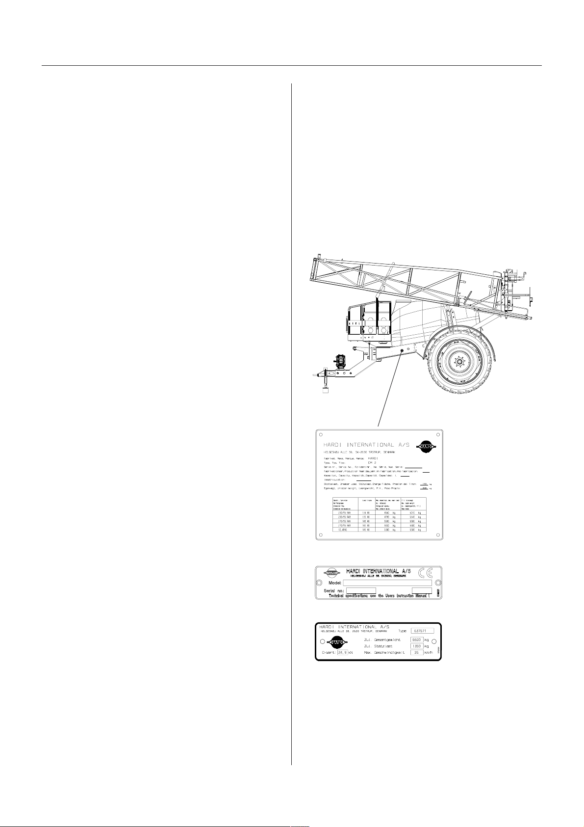
Identification plates
An identification plate fitted on the frame indicates
producer name, model, own weight, max. weight, max.
pressure of the hydraulic system, and max. pressure of
the spray liquid system. Frame, boom centre frame, and
inner/outer sections also have identification plates
indicating boom type and part number of spare parts. If
ordering spare parts, inform your dealer of these, so the
right model and version are described.
T271-0010x
The operating unit is constructed of modules and is
electrically controlled via a remote control box.
The built-in HARDI-MATIC ensures a constant volume
per hectare of the liquid (l/ha) at varying forward speed
within the same gear when the number of P.T.O. revolutions are between 300-600 r.p.m. (pump 540 r.p.m) or
650-1100 r.p.m. (pump 1000 r.p.m.).
Filters
With the self-cleaning filter the impurities that exist in the
spray liquid will bypass the filter and be recirculated back
to the tank via the return flow. Also suction filter and
nozzle filters are standard. In-line pressure filters can be
fitted as option.
Boom
All booms are suspended in a strong, stable parallelogram boom lift.
The HAY/HAZ booms are trapeze/pendulum suspended
and fully hydraulically operated, including boom slanting
control and air slot angling. HAZ models have Direct
Acting Hydraulics (D.A.H.) and individual boom tilt
function as well.
(Certain countries only)
T279-0005
T279-0002
T279-0006
The TWIN blowers are driven by a built-in hydrostatic
transmission powered via the tractor P.T.O. Blower
speed can be adjusted stepwise from the tractor cabin.
The HAY/HAZ booms are available in 18, 20, 21, 24, 27
GB 04 06
7
Page 8

Description
SprSpr
aa
yy
Spr
SprSpr
The HARDI COMMANDER sprayer is for the application
of crop protection chemicals and liquid fertilisers.
The equipment must only be used for this purpose. It is
not allowable to use the sprayer for other purposes.
If no local law demands that the operator must be
certified to use the spray equipment, it is strongly recommended to be trained in correct plant protection and in
safe handling of plant protection chemicals to avoid
unnecessary risk for persons and the environment when
doing the spray job.
er useer use
a
y
er use
aa
yy
er useer use
Unloading the sprUnloading the spr
Unloading the spr
Unloading the sprUnloading the spr
For the unloading of the sprayer a crane or a fork lift is
needed. When loading with a crane please observe the
lifting points as shown on the illustration, and make sure
that the straps or belts used for lifting are strong enough.
aa
a
aa
yy
er frer fr
y
er fr
yy
er frer fr
om the trom the tr
om the tr
om the trom the tr
ucuc
uc
ucuc
T021-0003
kk
k
kk
BefBef
oror
Bef
BefBef
operoper
oper
operoper
Although the sprayer has been applied with a strong and
protective surface treatment on steel parts, bolts etc. in
the factories, it is recommended to apply a film of
anticorrosion oil (e.g. CASTROL RUSTILLO or SHELL
ENSIS FLUID) on all metal parts in order to avoid
chemicals and fertilisers discolouring the enamel.
If this is done before the sprayer is put into operation for
the first time, it will always be easy to clean the sprayer
and keep the enamel shiny for many years.
This treatment should be carried out every time the
protection film is washed off.
8
e putting the spre putting the spr
or
e putting the spr
oror
e putting the spre putting the spr
aa
tiontion
a
tion
aa
tiontion
aa
yy
er intoer into
a
y
er into
aa
yy
er intoer into
GB 04 06
Page 9
Sprayer setup
Connecting the sprConnecting the spr
Connecting the spr
Connecting the sprConnecting the spr
DrDr
aa
wbarwbar
wbar
wbarwbar
ZPL/YPL
ss
s
ss
REDNAMMOC
DEXIF
RABWARD
Dr
a
DrDr
aa
Mounted on the chassis in a centre pivot, the drawbar
can be either standard fixed or optionally steered.
Steering can be hydraulically operated or it can be
automatically controlled (TRAIL CONTROL).
Overview - Drawbar systems
aa
a
aa
yy
erer
y
er
yy
erer
GNIREETS
RABWARD
LIART
LORTNOC
FLES
KCART
0082/0022seYseYseYseY
0024/0023seYseYseYoN
035
Following drawbar extensions are available. The drawbar extensions are available - steering or fixed - for both
high and low tractor hitch points. Each drawbar is
available in a long or a short version.
Overview - Drawbar extensions
REDNAMMOC
rabwarD
snoisnetxe
0082/0022
WOLdnaHGIH
hctih
REDNAMMOC
0024/0023
WOLdnaHGIH
hctih
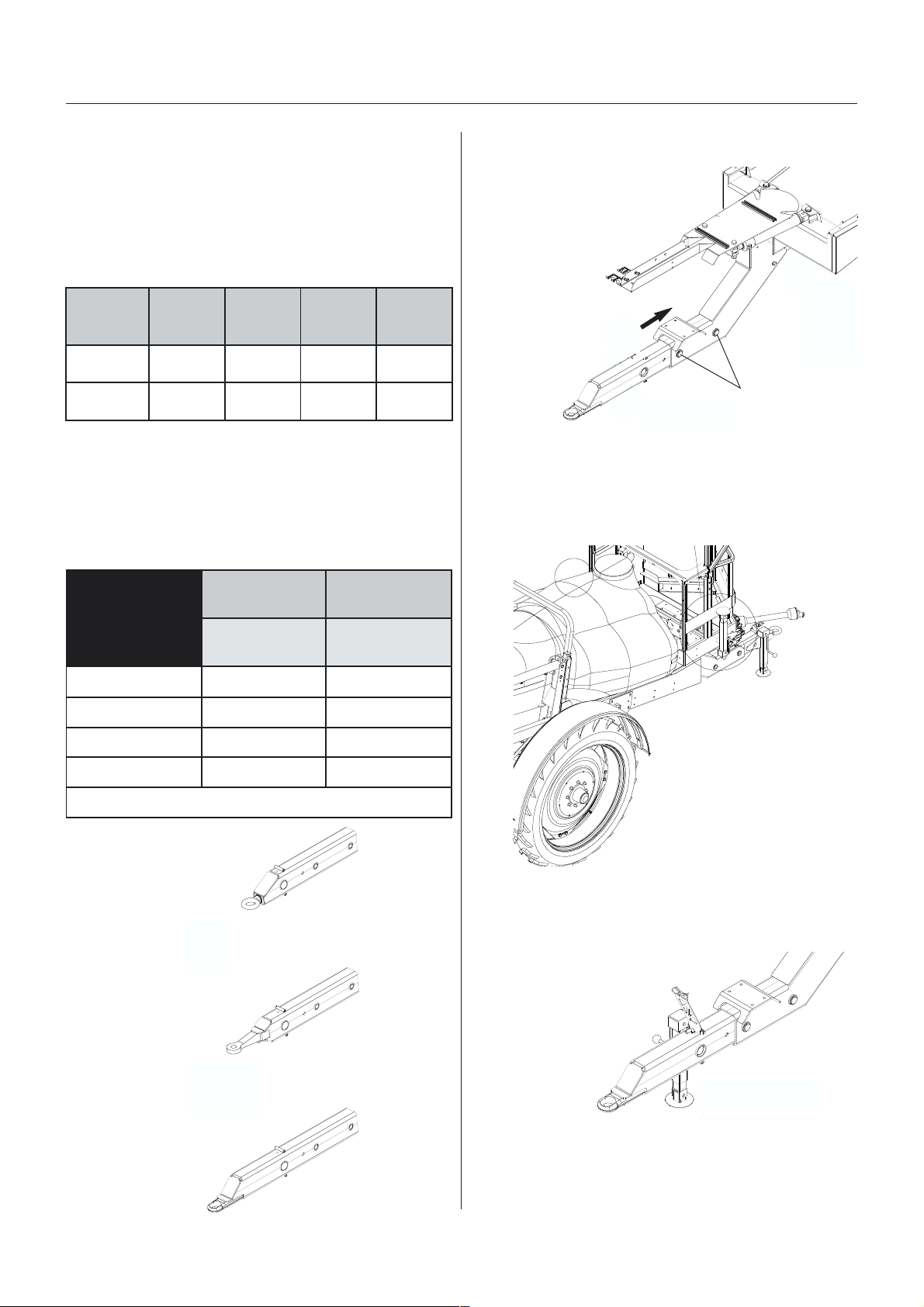
Mounting the drawbar extension
The extension piece is inserted into
the opening of the drawbar,
fastened by two main bolts
through the two holes A and
secured by two linch pins.
T251-0012x
A
Support leg
The support leg is stored in the bracket on the sprayers
right side when the sprayer is attached to the tractor.
33ØepytleviwSoNseY
63ØepytleviwSseYoN
04ØluamguZseYseY
)2965OSI(05ØhctiHseYseY
noisrevtrohsadnagnolanielbaliavaerasrabwardllA
Swivel type
Zugmaul
034
T142-0028x
To remove the support leg: Lift the leg, remove the linch
pin and pull out the support leg.
The support leg can then
be mounted to the drawbar
extension and secured by
linch pin.
T251-0012x
Hitch (ISO 5692)
T251-0014x
GB 05 02 01
9
Page 10

Sprayer setup
FF
ixix
ed dred dr
F
ix
ed dr
FF
ixix
ed dred dr
Make sure the drawbar points straight ahead from its
position on the trailer. If not, the two turn buckles A can
be adjusted till the drawbar is centred.
STEERING drSTEERING dr
STEERING dr
STEERING drSTEERING dr
Transport lock (if fitted)
The transport lock is a safeguard that will keep the
drawbar in a centred position in case of hydraulic
leakage during transport on public roads.
aa
wbarwbar
a
wbar
aa
wbarwbar
aa
wbarwbar
a
wbar
aa
wbarwbar
A
A
T251-0012x
T251-0016x
NOTE! If possible, lock the tractor hydraulic lever when
the lift arms are in the correct position to avoid the
sprayer weight resting on the stabiliser chains.
3. Tighten the lift arm stabiliser chains.
WARNING! Do not stand in the area around the
drawbar during manoeuvring.
The transport lock is fixed by linch pins.
If necessary, the transport lock can be adjusted by
turning the turnbuckle.
SELF TRASELF TRA
SELF TRA
SELF TRASELF TRA
SELF TRACK is connected as follows:
1. Attach the tractor lower links in the two mountings of
the SELF TRACK. Adjust the length of the drawbar if
necessary - to obtain the best tracking, choose the
setting where the distance X is equal to distance Y.
Secure with linch pins.
CK fCK f
or COMMANDER 2200/2800or COMMANDER 2200/2800
CK f
or COMMANDER 2200/2800
CK fCK f
or COMMANDER 2200/2800or COMMANDER 2200/2800
x
y
T251-0015x
TRAIL CONTROLTRAIL CONTROL
TRAIL CONTROL
TRAIL CONTROLTRAIL CONTROL
Please refer to separate instruction book.
Hose pacHose pac
Hose pac
Hose pacHose pac
To prevent hoses and wiring from being damaged by the
tractor wheels, all hoses, cables and wires are held by
the hose bracket A fitted to the drawbar.
kk
aa
gg
e suppore suppor
k
a
g
e suppor
kk
aa
gg
e suppore suppor
t t
t
t t
A
2. Attach safety chains to top link clevis. The chain will
prevent the transmission shaft from being damaged if
the lift arms are lowered too far. Adjust the chain
length so the chains are tight when the tractor P.T.O.
and pump shaft are in a horizontal line.
10
T251-0012x
Check that the length of the hoses and cables are
sufficient by tight turns.
GB 05 02 01
Page 11
Sprayer setup
TT
rr
ansmission shaftansmission shaft
T
r
ansmission shaft
TT
rr
ansmission shaftansmission shaft
OperOper
aa
Oper
OperOper
To avoid accidents and personal injuries, note the
following recommended precautions and safe operation
practices.
1. Always STOP ENGINE before attaching the transmis-
2. When attaching the shaft, make sure that the snap
3. Always keep protection guards and chains intact and
4. Do not touch or stand on the transmission shaft when
tor saftor saf
a
tor saf
aa
tor saftor saf
sion shaft to tractor P.T.O. - most tractor P.T.O. shafts
can be rotated by hand to facilitate spline alignment,
when engine is stopped.
lock is FULLY ENGAGED - push and pull shaft until it
locks.
WARNING! ROTATING TRANSMISSION
SHAFTS WITHOUT PROTECTION GUARDS
ARE FATAL.
make sure that it covers all rotating parts, including
CV-joints at each end of the shaft. Do not use without
protection guard.
it is rotating - safety distance: 1.5 meter.
etyety
ety
etyety
T259-0004
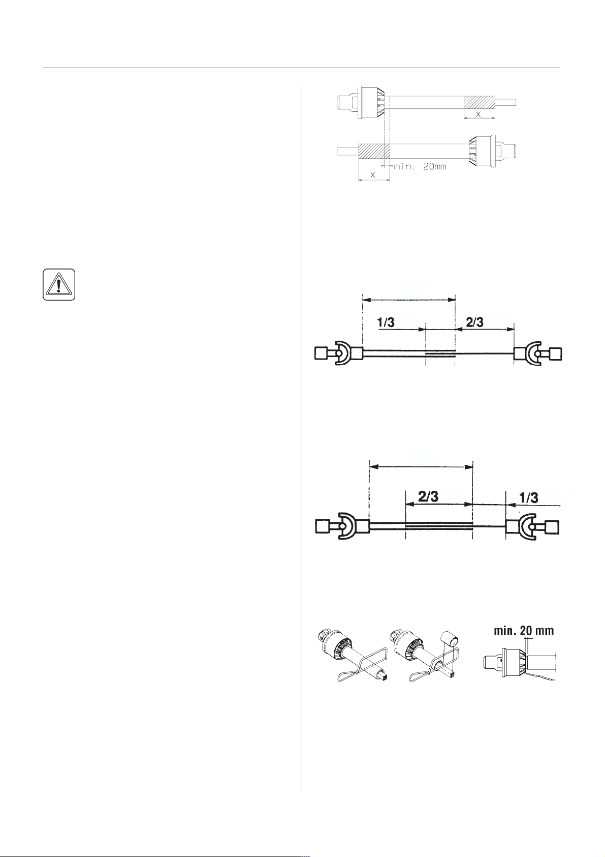
NOTE! The shaft must always have a minimum overlap.
The size of this overlap depends on the pump model:
Pump with 6 splines/540 r.p.m.
The shaft must always have an overlap of minimum 1/3
of the length.
T259-0011
5. Prevent protection guards from rotating by attaching
the chains allowing sufficient slack for turns.
6. Make sure that protection guards around tractor
P.T.O. and implement shaft are intact.
7. Always STOP ENGINE and remove the ignition key
before carrying out maintenance or repairs to the
transmission shaft or implement.
InstallaInstalla
Installa
InstallaInstalla
First installation of the transmission shaft is done in the
following way:
1. Attach sprayer to tractor and set sprayer height in the
2. Stop engine and remove ignition key.
3. If transmission shaft must be shortened, the shaft is
Fit the two shaft parts at tractor and sprayer pump
tion oftion of
tion of
tion oftion of
position with shortest distance between the tractor
and sprayer pump P.T.O. shafts.
pulled apart.
and measure how much it is necessary to shorten the
shaft.
tr tr
ansmission shaftansmission shaft
tr
ansmission shaft
tr tr
ansmission shaftansmission shaft
Pump with 21 splines/1000 r.p.m.
The shaft must always have an overlap of minimum 2/3
of the length.
T259-0011
4. The two parts are shortened equally. Use a saw, and
file the profiles afterwards to remove burrs.
T259-0005
5. Grease the tractor P.T.O. and pump shafts.
T259-0007
Mark the protection guards.
6. Fit the shaft to tractor P.T.O. and sprayer pump shaft.
NOTE: Female part marked with a tractor towards
tractor!
GB 05 03 01
11
Page 12

Sprayer setup
8. Twist the collar and slide the yoke onto the P.T.O.
shaft.
Make sure that the lock engages by pushing and
pulling the shaft forwards and backwards.
T259-0003
9. Fit the chains to prevent the protection guards from
rotating with the shaft.
T259-0008
NOTE!To ensure long life of the transmission shaft try to
avoid working- angles greater than 35°. The wide angle
shaft with Constant Velocity Joint works in angles up to
70°- 80° for short periods (during turning etc.).
T259-0002
12
GB 05 03 01
Page 13

Sprayer setup
TT
rr
acac
k gk g
augaug
T
r
ac
k g
TT
rr
acac
k gk g
Altering the trAltering the tr
Altering the tr
Altering the trAltering the tr
The track gauge of the COMMANDER can be altered
stepless as follows,
1. Measure the current track gauge (centre RH tyre to
centre LH tyre). Each side must be extended or
retracted half the desired alteration.
2. Attach the sprayer to tractor and engage tractor
parking brake.
3. Place stop wedges in front
of and behind RH wheel.
Jack up LH wheel, support
and secure sprayer body.
4. Loosen clamp bolts
for LH wheel axle.
5. Loosen the nut B on the brake operating arm.
Extend/retract this arm according to the adjustment of
the axle.
aug
augaug
ee
e
ee
acac
ac
acac
k gk g
k g
k gk g
augaug
aug
augaug
ee
e
ee
T251-0005
6. Extend or retract the axle.
A sack barrow and a
rod will facilitate the
operation.
T251-0006
7. If the rim position must be changed, do this first and
fine adjust by extending or retracting the axles.
Remember to tighten the wheel nuts to the specified
torque:
Rim plate to rim: 280 + 30 Nm (207 + 22 lbft)
Rim plate to hub: 490 Nm (288 lbft)
8. Tighten the clamp bolts to a torque of:
280 Nm (207 lb.ft) for 2200/2800
390 Nm (289 lbft) for 3200/4200.
COMMANDER
without suspension
B
9. Tighten nut B again.
IMPORTANT! Place the jack under the axle and lift the
wheel to remove load from the clamps before tightening
the clamp bolts to the specified torque.
10. Repeat the procedure on RH wheel.
11. Check the distance from centre tyre to centre of tank
frame is equal at RH and LH.
12. Retighten clamp bolts and wheel bolts to specified
torque after 8 hours of work.
T112-0005x
COMMANDER
with suspension
T112-0005x
B
GB 05 04 04
13
Page 14

Sprayer setup
Adjustment rAdjustment r
Adjustment r
Adjustment rAdjustment r
The maximum track width for all models is 2250 mm.
The minimum track width depends on the parameters in the charts beneath and whether the sprayer is equipped
with suspended axle or not. Please refer to the following charts (all figures are in mm).
Min. track width - Sprayers without suspension
&0SOXV
Spra y e r wi th:
)ODQJHKXE
%UDNH KXE
0XGJXDUGV
&0SOXV
Spra yer with:
)ODQJHKXE
%UDNH KXE
angang
es - tres - tr
ang
es - tr
angang
es - tres - tr
[ [ [ [ [ [ [
[ [ [ [ [ [ [
acac
k widthk width
ac
k width
acac
k widthk width
7\UHVL]H
7\UHVL]H
0XGJXDUGV
&0SOXV
Spra yer wit h :
)ODQJHKXE
%UDNH KXE
0XGJXDUGV
[ [ [ [ [ [ [
&0SOXV
Spra y e r wi th:
)ODQJHKXE
%UDNH KXE
0XGJXDUGV
Min. track width - Sprayers with suspension
[ [ [ [ [ [ [
7\UHVL]H
7\UHVL]H
&0SOXV
Spra yer with:
)ODQJHKXE
%UDNH KXE
0XGJXDUGV
14
7\UHVL]H
[ [ [ [ [ [ [
GB 05 04 04
Page 15
Sprayer setup
&0SOXV
Spra y e r wi th:
)ODQJHKXE
%UDNH KXE
0XGJXDUGV
&0SOXV
Sp rayer wit h :
)ODQJHKXE
%UDNH KXE
0XGJXDUGV
&0SOXV
Sp ray e r wi t h:
)ODQJH KXE
%UDNH KXE
7\UHVL]H
[ [ [ [ [ [ [
7\UHVL]H
[ [ [ [ [ [ [
7\UHVL]H
[ [ [ [ [ [ [
0XGJXDUGV
It is not permitted to fit dual wheels!
IMPORTANT! On TRACKER models a minimum track gauge of 1800 mm is strongly recommended to ensure
stability and to avoid the sprayer tipping over.
NOTE! The wider the track gauge, the better the stability of the sprayer and boom.
PP
ermitted rim positionsermitted rim positions
P
ermitted rim positions
PP
ermitted rim positionsermitted rim positions
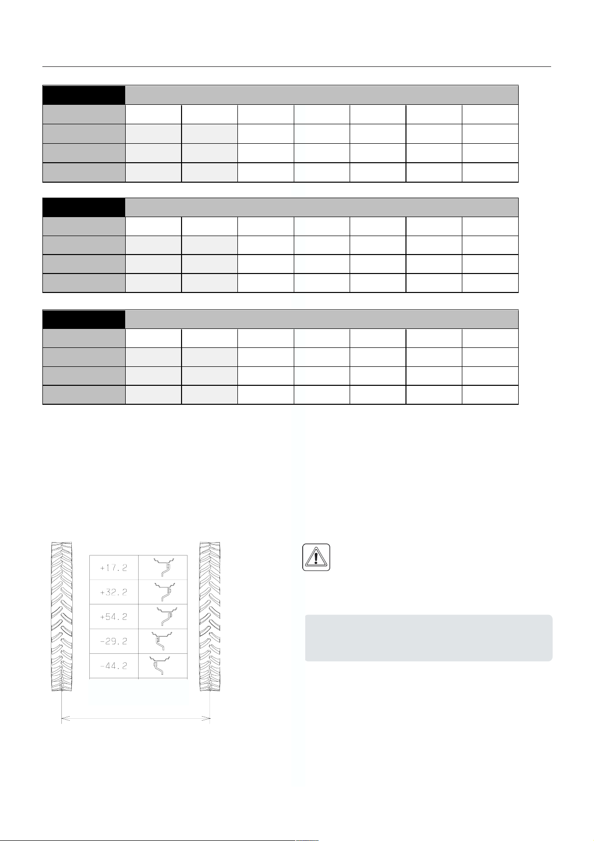
WARNING! When altering track gauge by turning
rims and rim plates the maximum permitted
offset between centre wheel and hub flange must
be observed:
Max offset, hub flange and centre rim:
CM Min. rim offset Max. rim offset
2200/2800 -45 +55
3200/4200 -33 +33
T251-0003
T251-0004
IMPORTANT! Tyre sizes 18.4 x 38 and 20.8 x 38
are not permitted in any + position, only use the
- positions.
GB 05 04 04
15
Page 16
Sprayer setup
HyHy
drdr
Hy
HyHy
HyHy
Hy
HyHy
Tractor Operated Hydraulics
Connection requirements for COMMANDER-HAY are
one double acting and one single acting spool valve.
Single acting valve: Boom lift, up/down
Double acting valve: Boom folding and unfolding
Ensure the snap couplers are clean before connection!
aulic syaulic sy
dr
aulic sy
drdr
aulic syaulic sy
drdr
aulics COMMANDER-HAaulics COMMANDER-HA
dr
aulics COMMANDER-HA
drdr
aulics COMMANDER-HAaulics COMMANDER-HA
stemsstems
stems
stemsstems
YY
Y
YY
Flow regulator
If hydraulic slanting control is fitted another double acting
spool valve on the tractor is required.
NOTE! The hydraulic system requires a minimum oil
pressure of 130 bar, max. oil pressure of 210 bar and an
oil capacity of approx. 5 litres. After having operated the
boom and the system has been filled with oil, check
tractors hydraulic oil level and top up if necessary.
HyHy
drdr
aulics COMMANDER-HAZaulics COMMANDER-HAZ
Hy
dr
aulics COMMANDER-HAZ
HyHy
drdr
aulics COMMANDER-HAZaulics COMMANDER-HAZ
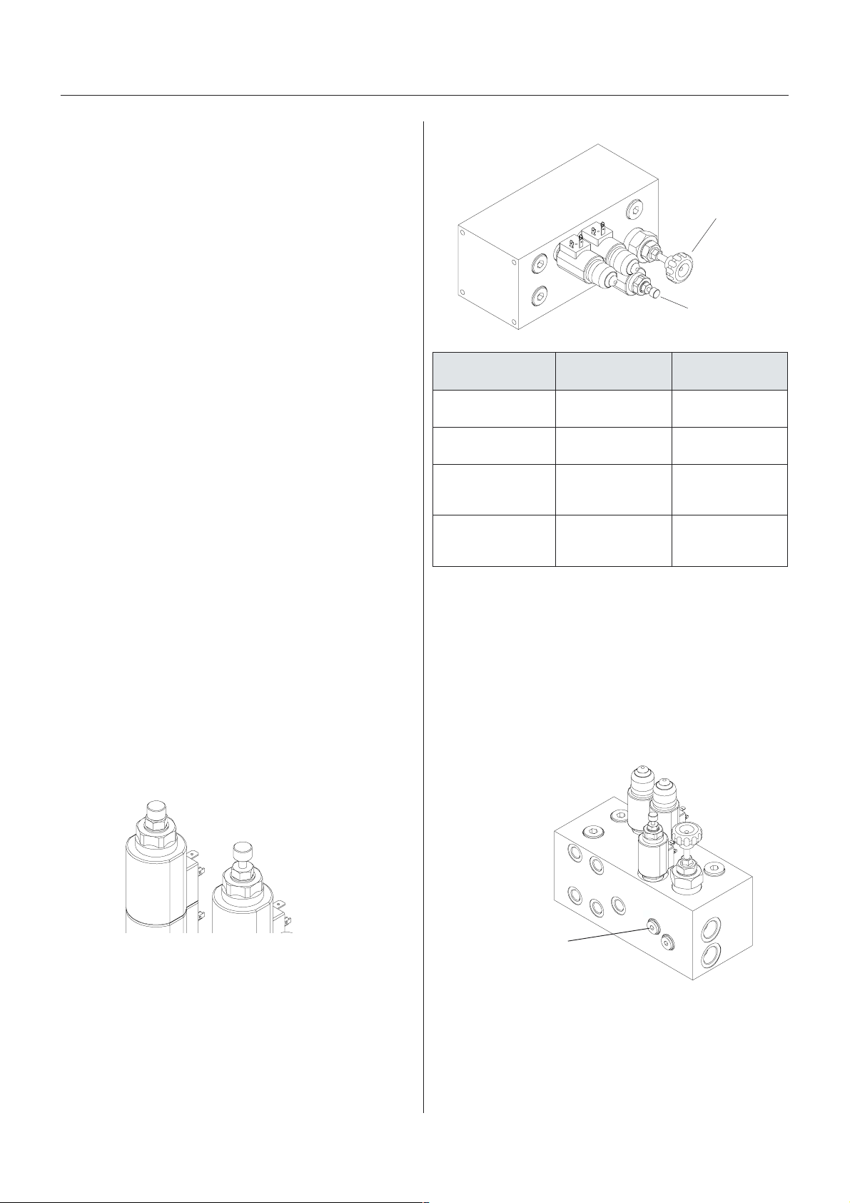
Direct Acting Hydraulic system
The D.A.H. system requires a double acting hydraulic
outlet. The hydraulic hoses are marked with arrows to
indicate direction of oil flow.
The D.A.H. system requires an oil flow between 10 and
90 l/min (19.8 Imp. gal/min.) and a min. pressure of 130
bar (1886 p.s.i.) The system has a built-in flow regulator
that maintains constant speed on hydraulic movements.
The hydraulic distribution block is situated underneath
the platform floor.
The valves on the block are operated by means of
manual override and each valve can be regulated to be
open or closed.
T112-0004x
metsys
dradnatS
.1 tuohtiW lanretxe
.2 htiW lanretxe
Load Sensing
Please consult your tractor dealer for correct setup and
correct connection.
Certain tractor models are able to use Load Sensing
without connecting an external sensing line (setting 1 in
scheme). But if optimal sensing control pressure cannot
be obtained, an external sensing line needs to be
mounted (setting 2 in scheme).
ciluardyh/rotcarT
)rotcartwolftnatsnoc(
ertnecdesolC
)srotcartDJniatrec(
gnisnesdaoL
enilgnisnes
gnisnesdaoL
enilgnisnes
nepOnepO
desolCdesolC
nepOnepO
desolCnepO
Cartridge valve
evlavegdirtraC rotalugerwolF
029
Valve closed
Valve open
T112-0004x
Before operating the hydraulics, the valves on the
sprayers hydraulic distribution block should be adjusted
according to the specific tractor model (please refer to
scheme later in this part).
If you have doubt about which type of hydraulic system
your tractor is equipped with, please ask your tractor
dealer.
16
Connect hose to
LS on the
distribution block
Requirements - Load Sensing hose:
1/4 Standard hose
Max. rated working pressure = 200 bar.
IMPORTANT! It is of essential importance that connectors on sensing line are kept totally clean. Failure to do
so will cause impurities entering the pump and thereby
cause damages to vital pump parts.
GB 05 06 06
LS
T112-0007x
Page 17
Sprayer setup
ContrContr
Contr
ContrContr
Power requirement is 12V DC.
Note Polarity!
For EVC: Brown pos. (+), Blue neg. (-).
For D.A.H.: White pos. (+), Black neg. (-).
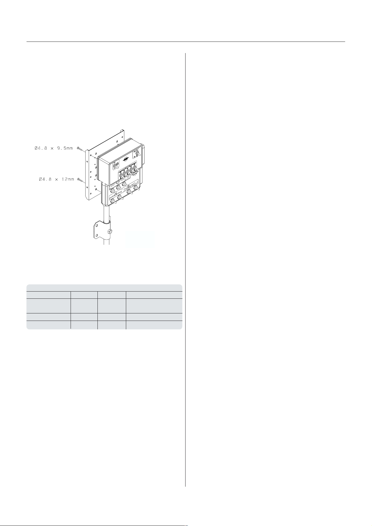
The control boxes for EVC-operating unit and D.A.H. are
fitted in the tractor cabin at a convenient place. Tapping
screws can be used for mounting.
ol bool bo
ol bo
ol bool bo
xx
es and powes and pow
x
es and pow
xx
es and powes and pow
er supplyer supply
er supply
er supplyer supply
T165-0013
The wires must have a cross sectional area of at least
4.0 mm to ensure sufficient power supply. For the EVCoperating unit the tractor circuit should have an 8 Amp
fuse and for the D.A.H. an 16 Amp fuse.
Control box for Polarity (wire colour) Required Fuse, Amp
Positive + Negative EVC operating
unit Brown Blue 8
D.A.H. Hydraulic White Black 16
MANIFOLD valve Brown Blue 8
Use the HARDI Electric distribution box (No. 817925) if
the tractor has a doubtful power supply.
GB 05 06 06
17
Page 18
Sprayer setup
BrBr
akak
Br
BrBr
EmerEmer
Emer
EmerEmer
The parking brake lever has two function modes, which
are determined by the small pawl control clip (A).
To change between the
two modes, turn the clip.
Pos. 1: The pawl control
clip must point away from
the pawl.
Pos. 2: The pawl control
clip must rest against the
pawl.
To disengage the parking
brake:
1. Set pawl control clip in pos. 1.
2. Pull the lever a little forward to release the pawl from
To engage the parking brake:
1. Set pawl control clip in pos. 2.
2. Pull the lever firmly forwards until parking brake is fully
eses
ak
es
akak
eses
gg
encenc
y and pary and par
g
enc
y and par
gg
encenc
y and pary and par
the ratchet and then push the lever fully backwards.
engaged.
kk
ing bring br
k
ing br
kk
ing bring br
akak
e (ife (if
ak
e (if
akak
e (ife (if
A
Forward
f f
itted)itted)
f
itted)
f f
itted)itted)
B
12
Backward
T021-0001
Tractor Trailer
Oil
reservoir
Hydraulic pump
WARNING! Do not connect the brakes directly to
the tractor hydraulics without the brake valve. The
trailer brake power cannot be controlled, and
braking will therefore be hazardous.
IMPORTANT! Max. oil pressure is 150 bar (2175 p.s.i.)
in the brake line.
Relieve parking brake before driving.
Air activAir activ
Air activ
Air activAir activ
This system requires a tractor with
compressor and air brake system with
out-let(s) for trailer brakes.
aa
ted brted br
a
ted br
aa
ted brted br
akak
ak
akak
es (ifes (if
es (if
es (ifes (if
f f
itted)itted)
f
itted)
f f
itted)itted)
T021-0008
Emergency brake
1. Set pawl clip in pos. 2.
2. Attach the rope from the hole in top of the handbrake
lever (B) to e.g. the tractor top link attaching point. If
the sprayer is accidentally unhooked during transport
the rope will apply the parking brake before the rope
breaks.
IMPORTANT! To ensure safe engagement and to avoid
damages to the parking brake use rope with an ultimate
stress between 690 N (155 lb.) and 785 N (176 lb.).
HyHy
drdr
aulic activaulic activ
Hy
dr
aulic activ
HyHy
drdr
aulic activaulic activ
This requires a special trailer brake valve attached to the
tractor hydraulic and brake system. Connect the snap
coupler to the tractor brake outlet. When the tractor
brakes are applied, the trailer brakes will work proportionally to the tractor brakes, and ensure safe and
effective braking.
aa
ted brted br
a
ted br
aa
ted brted br
akak
ak
akak
es (ifes (if
es (if
es (ifes (if
f f
itted)itted)
f
itted)
f f
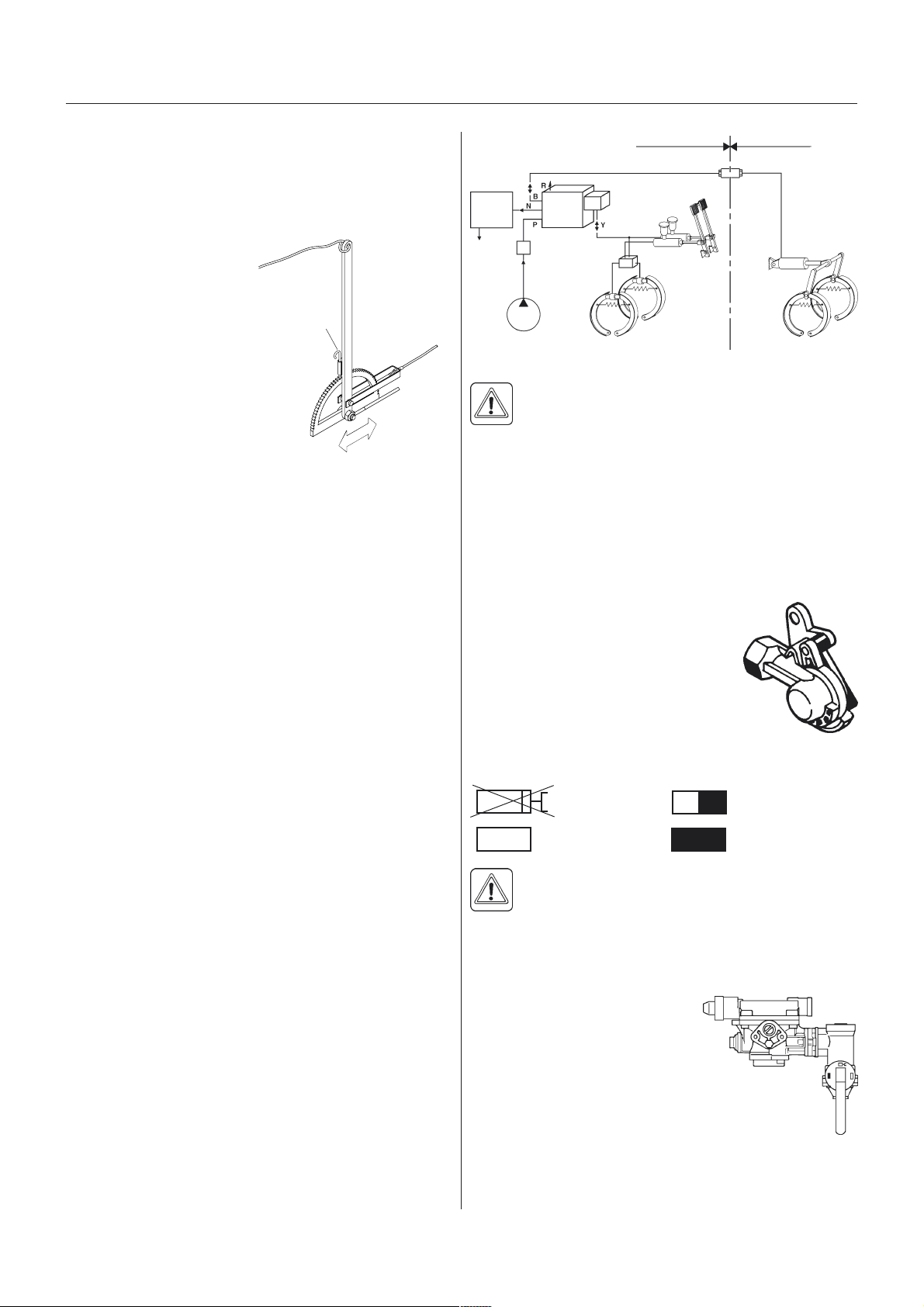
itted)itted)
IMPORTANT! The load apportioning
valve must be set at the position
corresponding to the load on the
trailer, for obtaining optimal air pressure to the trailer brakes.
= Relieved = Half full tank
= Empty tank = Full tank
WARNING! Driving with wrong load apportioning
valve setting, will make the brakes under- or overapply, which can cause hazardous situations.
NOTE! If the air hose(s) are disconnected with air in the
brake air tank, control pressure
will be dumped and the brakes
will engage fully. If the sprayer
must be moved with air in the
tank and without the air hose(s)
connected to the tractor, the load
apportioning valve must be set
at relieved to disengage the
brakes. Remember to reset the
handle to brake position again
afterwards. When parking the
sprayer, always engage the parking brake, as the air
brakes will only be engaged as long as there is air in the
tank! Cover the couplings with the dust flaps when
hoses are disconnected.
T021-0009
Load valve
Position
setting
T021-0010
18
GB 05 05 02
Page 19

Sprayer setup
SingSing
le-line brle-line br
Sing
le-line br
SingSing
le-line brle-line br
Flip the snap coupler protection flap away and connect
the brake system snap coupler to the tractor outlet
(black) and let the compressor fill the sprayers air
reservoir.
Check brake circuit for leaks.
akak
ak
akak
es (ifes (if
es (if
es (ifes (if
f f
itted)itted)
f
itted)
f f
itted)itted)
Dual-line brDual-line br
Dual-line br
Dual-line brDual-line br
Flip the snap coupler protection flaps away and connect
the two snap couplers for supply and control to the
tractor outlets, and check brake circuits for leaks.
The couplers are colour coded and secured against
incorrect attachment:
Red = Supply line (RH)
Yellow= Control line (LH)
Relieve parking brake before driving
akak
ak
akak
es (ifes (if
es (if
es (ifes (if
f f
itted)itted)
f
itted)
f f
itted)itted)
GB 05 05 02
19
Page 20
Sprayer setup
Counter wCounter w
Counter w
Counter wCounter w
eight eight
eight
eight eight
(TRA(TRA
CKER models only)CKER models only)
(TRA
CKER models only)
(TRA(TRA
CKER models only)CKER models only)
To improve stability on TRACKER models, extra weight
can be added by means of liquid-filled tyres.
The standard tyre valve is an universal air-water valve.
The tyres can be filled with liquid to max. 75% of their
total volume. The table below indicates the 75% volume.
eziseryT erytrepdiuqilfosertil.xaM
"44x5.9101
"84x5.9 801
"44x2.11331
"84x2.11 441
"64x4.21871
"83x9.61 582
"83x4.81093
"83x8.02 664
1 litre = 0.264 US Gal. 1 litre = 0.22 Imp. Gal.
001
Use a mixture of water and CaCl2 to avoid frost damage
as described in table below:
Recommended tyre pressure:
eziseryT
59CR
44R59/032
)44x5.9(
84R59/032
)84x5.9(
44R59/072
)44x2.11(
84R59/072
)84x2.11(
64x4.21)25(6.3851/741
83x9.61 )32(6.1 251/141
83x4.81)32(6.1441/741
83x8.02 )81(2.1 151/451
dednemmoceR
nierusserpnoitalfni
).i.s.p(rab
)25(6.3541/431
)25(6.3 741/631
)25(6.3151/041
)25(6.3 351/241
muminiM
xednIdaoL
2A/8A
NOTE! When filling the tyres the valve should be positioned at 12 oclock and when adjusting the tyre pressure, the valve should be positioned at 6 oclock.
002
CaCl2 per litre water Protection to
200 g (7.1 oz) -15°C (30.6°F)
300 g (10.6 oz) -25°C (12.6°F)
435 g (15.4 oz) -35°C (-5.4°F)
WARNING! It is very important that the CaCl2 is
added to the water and agitated until it is fully
dissolved. Never pour water on to CaCl2! If you
get CaCl2 in the eyes, flush instantly with cold water for
at least 5 minutes and seek medical advice afterwards.
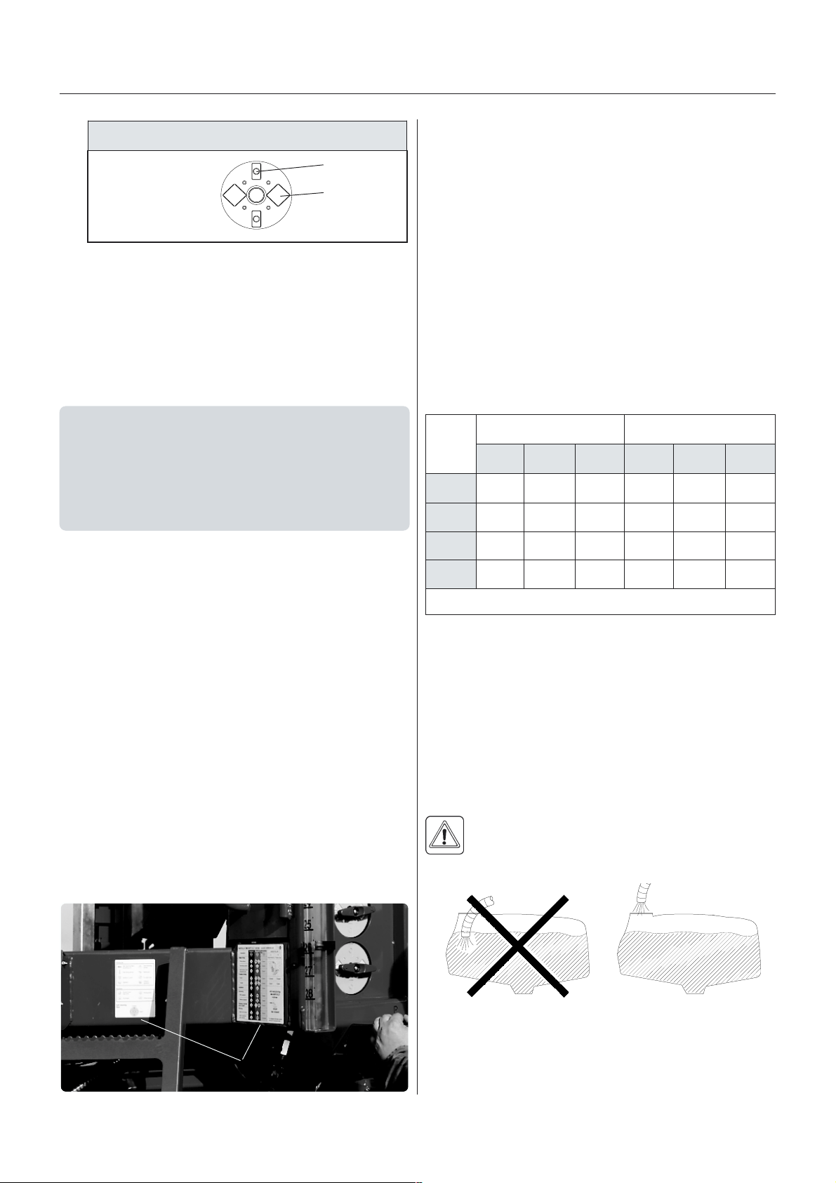
IMPORTANT! The tyres must be liquid filled to max. 75
% of total tyre volume. Fill only the qty. of liquid necessary to obtain sufficient stability of the sprayer. Do not fill
liquid and CaCl2 mixture in tyres without tubes!
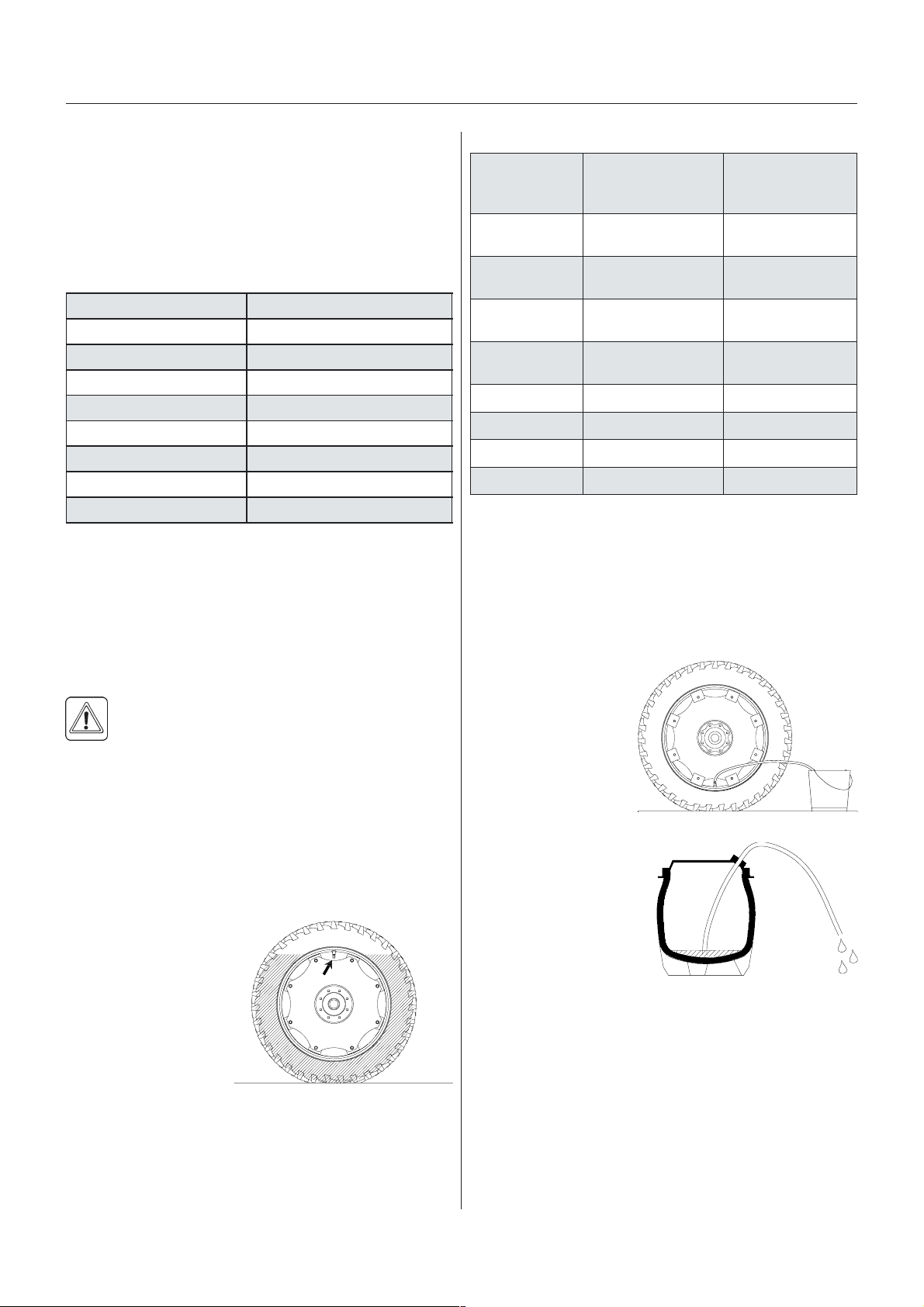
To fill the tyres:
1. Jack up the wheel
and rotate wheel till
the valve is positioned at 12 oclock.
2. Remove the valve
body and fill liquid
until it reaches the
valve.
T021-0011
3. When surplus liquid
is drained through the
valve stem fit the valve body again.
4. Adjust tyre pressure and lower the wheel. (Please
refer to table for correct tyre pressure).
To empty the tyres:
1. Rotate wheel till the
valve is positioned at
6 oclock.
2. Remove the valve
body and let out the
liquid. Retain liquid in
an appropriate
container.
3. To empty the tyre
completely the tyre is
inflated and a thin drain
tube is lead to the
bottom of the tyre. The
air pressure will now
empty the remaining
liquid.
4. Remove the drain tube,
fit the valve and inflate
the tyre to specified
pressure. See the table Tyre pressure.
NOTE! Disposal of CaCl
has to take place according to
2
local legislation.
T021-0013
T021-0014
20
GB 05 10
Page 21
Sprayer setup
TT
rr
ansporanspor
T
r
anspor
TT
rr
ansporanspor
RR
oadwoadw
R
oadw
RR
oadwoadw
When driving on public roads and other areas where the
highway code applies, or areas where there are special
rules and regulations for marking and lights on implements, observe these and equip implements accordingly.
NOTE! Max. driving speed is 25 km/h for models without
brakes and 40 km/h for models equipped with brakes.
tt
t
tt
oror
thinessthiness
or
thiness
oror
thinessthiness
TT
rr
ansporanspor
T
r
anspor
TT
rr
ansporanspor
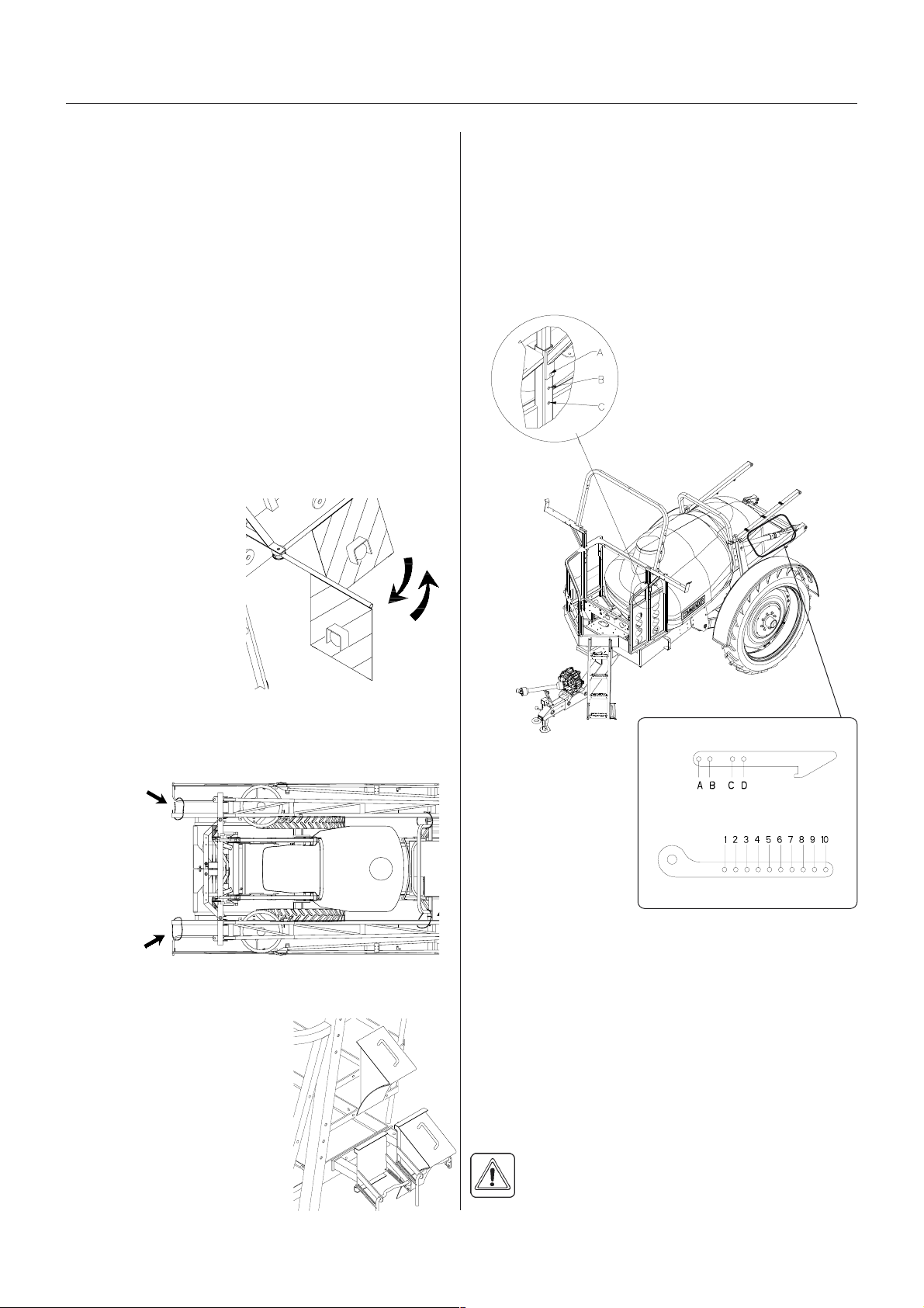
The transport brackets can be set in different positions.
Thereby it is possible to obtain different transport heights
and suitable clearance above various tractor cabins.
When changing the setting of the transport brackets it is
done as a combination of adjusting the transport brackets themselves (1) and adjusting the transport locks (2).
Always choose a transport height as low as possible.
t brt br
t br
t brt br
acac
ac
acac
kk
etsets
, height setting, height setting
k
ets
, height setting
kk
etsets
, height setting, height setting
RR
ear lights (ifear lights (if
R
ear lights (if
RR
ear lights (ifear lights (if
Connect plug for rear lights to the tractors 7-pin socket,
and check function of rear lights, stop lights and direction
indicators on both sides before driving.
The wiring is in accordance with ISO 1724. See section
on Technical specifications.
Before transport on
public roads the front
warning boards with
position lamps must be
folded out (fitted in
certain countries only).
Boom trBoom tr
Boom tr
Boom trBoom tr
Fit the safety chains as shown below before transport on
public road.
ansporanspor
anspor
ansporanspor
f f
itted)itted)
f
itted)
f f
itted)itted)
t saft saf
t saf
t saft saf
ety cety c
ety c
ety cety c
hain (ifhain (if
hain (if
hain (ifhain (if
f f
itted)itted)
f
itted)
f f
itted)itted)
T042-0003
(1)
T142-0026
1. Transport brackets
The transport bracket can be
set at three different positions
A, B or C.
Loosen the bolt to change
position and replace it according to new setting. The setting
must be identical on both
sides.
(2)
A
T030-0001
Stop wStop w
Stop w
Stop wStop w
Before driving, remove the
stop wedges and place them
in the storage brackets.
edgedg
edg
edgedg
es (ifes (if
es (if
es (ifes (if
f f
itted)itted)
f
itted)
f f
itted)itted)
T021-0004
2. Transport lock
To change position:
B
1. Lift and unfold inner sections till lock is disengaged.
2. Loosen and remove the two bolts, which keep the
parts A and B assembled.
3. Reassemble A and B according to desired hole
combination.
NOTE! Always use both bolts to assemble the lock. The
setting must be identical on both sides.
NOTE! The rear settings must correspond to the front
settings so the boom is resting on the front as well as
rear brackets.
WARNING! The max. transport height must
never exceed 4.0 m (13.1 ft.). Always measure
the actual total height and choose settings not
exceeding 4.0 m.
GB 05 08 05
T101-0031
21
Page 22
Sprayer setup
TT
rr
ansporanspor
T
r
anspor
TT
rr
ansporanspor
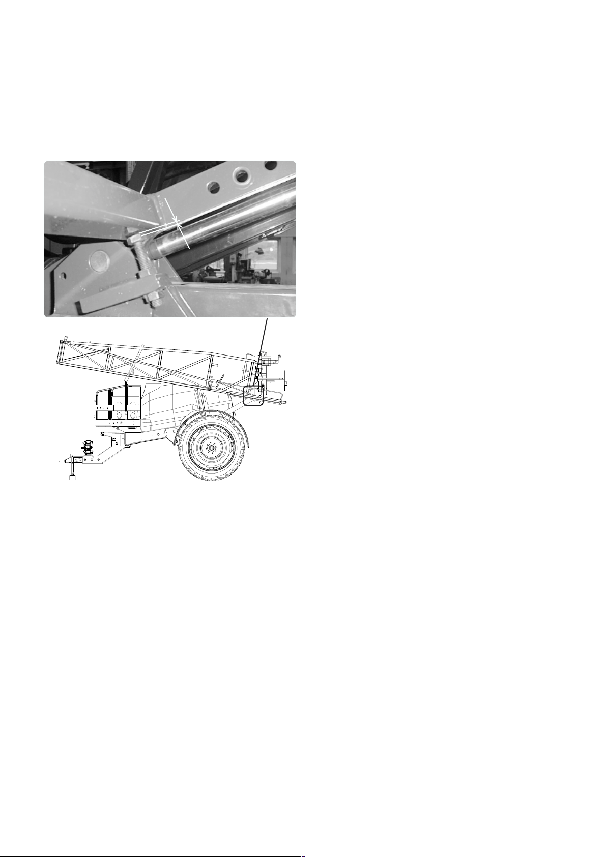
When the boom is unfolded: Inspect the gap between
the bolt A and the frame. Correct position = 1 mm gap.
If necessary, adjust the position of bolt A.
t loct loc
t loc
t loct loc
kk
k
kk
1 mm
A
T060-0128
T271-0010x
22
GB 05 08 05
Page 23

Sprayer setup
Driving TDriving T
Driving T
Driving TDriving T
STEER TRASTEER TRA
STEER TRA
STEER TRASTEER TRA
A trailer with articulating drawbar (TRACKER) behaves
differently than a normal trailer.
In tracking position the vehicle centre of gravity is
displaced further more compared to the vehicle centre
line of a normal trailer.
Compared to a conventional trailer a TRACKER has
decreased stability when turning, especially when turning
on hillsides.
To avoid overbalancing, pay attention to these guidelines:
1. Avoid sudden, tight turns
2. Slow down before entering a curve or turning, and
drive with a constant, low speed during the turn.
3. Never slow down too fast, never brake heavily and
never stop suddenly in a curve, or when turning on a
hillside, when the sprayer is articulated.
4. Be careful when turning on uneven ground
5. Set the track gauge as wide as possible
6. The proper function of the hydraulic damping is
essential to obtain good stability
7. Keep stabiliser chains on the tractors liftarms tight
8. For safety reasons, the following limitations are set for
TRACKERS (with unfolded booms):
ecec
hniquehnique
ec
hnique
ecec
hniquehnique
CK and SELF TRACK and SELF TRA
CK and SELF TRA
CK and SELF TRACK and SELF TRA
CKCK
CK
CKCK
NOTE! HARDI cannot
undertake any responsibility
for any damages caused by
the sprayer tipping over.
T029-0002
STEER TRASTEER TRA
STEER TRA
STEER TRASTEER TRA
(If the sprayer is equipped with HARDI NOVA, please
see separate instruction book).
The articulating drawbar on STEER TRACK is to be
operated manually via the D.A.H.
The switch on the D.A.H. control box is pushed sidewards to articulate the drawbar.
This is used when turning or as track correction when
driving on slopes.
CKCK
CK
CKCK
Speed by turning, max. 4 km/h (2.5 m.p.h.)
Ground inclination by turning, max. 8°
Track gauge, min. Please see the part
Track gauge
MAX. 4 KM/H
T029-0003
T029-0003
GB 06 02
T029-0004
23
Page 24

Sprayer setup
SELF TRASELF TRA
SELF TRA
SELF TRASELF TRA
The SELF TRACK is always in tracking mode.
The SELF TRACK drawbar will always articulate when
the tractor is turning and follow the tractor rear wheels.
The SELF TRACK drawbar is hydraulically damped to
obtain stable trailing.
to avoid the vehicle from tipping over.
TRAIL CONTROLTRAIL CONTROL
TRAIL CONTROL
TRAIL CONTROLTRAIL CONTROL
Please see separate instruction book.
CKCK
CK
CKCK
WARNING! Always drive the SELF TRACK very
carefully on public roads, and be aware of the
sprayers behaviour. Slow down before turning,
24
GB 06 02
Page 25

Equipment - StandarEquipment - Standar
Equipment - Standar
Equipment - StandarEquipment - Standar
LadderLadder
Ladder
LadderLadder
Sprayer setup
d and Additionald and Additional
d and Additional
d and Additionald and Additional
LarLar
gg
e store stor
Lar
g
e stor
LarLar
gg
e store stor
The locker A can be mounted on the sprayers right side
acting as a storage for sealed pesticide containers. The
locker is fitted to a mounting B, which is bolted to the
frame of the trailer.
A drain in the bottom makes it possible to clean and
drain the locker in case of leak by pesticide containers.
aa
gg
a
g
aa
gg
e Loce Loc
e Loc
e Loce Loc
kk
er (ifer (if
k
er (if
kk
er (ifer (if
f f
itted)itted)
f
itted)
f f
itted)itted)
A
C
T060-0121
Down: Pull the handle A to disengage the locking device
and drag down the ladder while supporting it by both
handles (B + C)
Up: The ladder will lock automatically when it is fully
retracted.
NOTE! Always retract the ladder before driving.
If necessary, grease the slide bars to make the ladder
slide smoother.
PlaPla
tftf
ormorm
Pla
tf
orm
PlaPla
tftf
ormorm
Access to the platform is possible via the ladder.
Hydraulic and electric components are situated underneath the platform floor. By lifting the platform floor,
these components are accessible. Also the clean water
tank is integrated in the platform.
B
B
T142-0025x
Small storSmall stor
Small stor
Small storSmall stor
The locker A can be mounted next to the HARDI
FILLER. It is for the purpose of storing pesticide containers in use, nozzles, calibration- and compound equipment. The locker is fitted to a mounting B, which is
bolted to the frame of the trailer.
B
aa
gg
a
g
aa
gg
e Loce Loc
e Loc
e Loce Loc
kk
er (ifer (if
k
er (if
kk
er (ifer (if
A
f f
itted)itted)
f
itted)
f f
itted)itted)
A
The platform gives
access to the clean
water tank lid, the
main tank lid, the top
mounted suction
filter and the selfcleaning filter, which
is situated behind the
wicket A on the
backside of the
MANIFOLD system.
TT
ank leank le
T
ank le
TT
ank leank le
indicaindica
indica
indicaindica
The actual tank level
in the main tank can
be observed on the
tank level indicator B. The scale is displayed in litres or
Imp. gal/US gal. (certain countries).
vv
v
vv
tortor
tor
tortor
elel
el
elel
A
B
T060-0114
T142-0024x
A drain in the bottom makes it possible to clean and
drain the locker in case of leak by pesticide containers.
FF
rr
ont Locont Loc
F
r
ont Loc
FF
rr
ont Locont Loc
The locker is mounted to the front of the platform. It is
for the purpose of storing non-contaminated protective
gear, soap for hand washing etc.
The locker is split in two compartments for the separation of clean clothes from gloves with risk of contamination.
GB 05 09 02
kk
er (ifer (if
k
er (if
kk
er (ifer (if
f f
itted)itted)
f
itted)
f f
itted)itted)
25
Page 26

Sprayer setup
Boom light
(A)
Work light
(B)
Two compartments
The work light lamp B is also mounted to the railing of
the platform above the MANIFOLD valves. This lamp is
positioned to lighten the HARDI FILLER + the MANIFOLD system.
It is recommended to switch of the rear lights of the
tractor in order to save power consumption and to avoid
reflection.
Power supply is via the 7-pin socket. Please see the
Installation Instruction in the part Technical specifica-
tions.
T060-0110
A soap dispenser can be fitted in a device on the inside
of the locker door.
IMPORTANT! Although this locker is situated in the noncontaminated zone of the sprayer and is meant for
storing nontoxic items, it must never be used for storing
food, beverage or other things meant for consumption.
Boom and WBoom and W
Boom and W
Boom and WBoom and W
oror
k lights (ifk lights (if
or
k lights (if
oror
k lights (ifk lights (if
f f
itted)itted)
f
itted)
f f
itted)itted)
Selector switch
When mounting the selector switch A it is simply
clicked into the cutout in the frame below the MANIFOLD valves an is thereby fastened to the frame.
A
T060-0112
The switch has three positions:
1. Boom lights ON
T271-0009
The 2 boom light lamps A are mounted to the railing of
the platform (one at each side) and are positioned to
lighten both boom wings.
T060-0111
26
2. Lights OFF (neutral)
3. Work light ON
T040-0000
T040-0001
Connection box
The connection box is to be mounted underneath the
platform floor.
1. Lift the platform floor
2. Open the connection box and mount the flat part of
the box (A) by 4 screw to the 4 predrilled holes in the
platform floor.
GB 05 09 02
Page 27
Sprayer setup
Drag the split, twist
it 900 and drop the
split again to lock it
A
T060-0123
CrCr
op prop pr
Cr
CrCr
The kit consists of sheet, straw dividers and wheel brake
covers.
otection Kit (ifotection Kit (if
op pr
otection Kit (if
op prop pr
otection Kit (ifotection Kit (if
f f
itted)itted)
f
itted)
f f
itted)itted)
Each cutout in the shield is then fastened with a matching locking device, which are mounted along the lower
part of the sprayer.
T066-0074
Strawdividers
A strawdivider can be fitted on each trailer wheel.
Sheet
The PVC sheet is fitted underneath the trailer and
covers the undercarriage of the chassis
T060-0113
The sheet is lead through guiding rails fastened on both
sides of the trailer.
T060-0125
Wheel brake covers
A wheel brake cover A can be mounted in order to cover
the brake
A
T066-0073
GB 05 09 02
T060-0126
27
Page 28

Sprayer setup
MudguarMudguar
Mudguar
MudguarMudguar
Mudguards can be fitted on the trailer wheels by means
of a supporting frame which is bolted to a mounting on
the wheel axle.
ds (ifds (if
ds (if
ds (ifds (if
f f
itted)itted)
f
itted)
f f
itted)itted)
T060-0127
Mudguards are available for all wheel configurations.
T162-0109x
28
GB 05 09 02
Page 29

Sprayer setup
Disconnecting the sprDisconnecting the spr
Disconnecting the spr
Disconnecting the sprDisconnecting the spr
Always clean the sprayer - inside and outside - before
disconnecting and parking it.
Support leg
Before disconnecting from the tractor, make sure the
support leg is properly fitted and secured by linch pin.
T251-0012x
The support leg is stored in the bracket on the right side
of the trailer when the sprayer is attached to the tractor.
To remove the support leg: Lift the leg, remove the linch
pin and pull out the support leg.
a
aa
yy
erer
y
er
aa
yy
erer
Transmission shaft support
The transmission shaft rests on the bracket A when not
in use (Low hitch models).
A
T142-0029x
At High hitch models the transmission shaft is placed in
the hook underneath the drawbar when not in use
WARNING! To prevent the sprayer from tipping
over, do not disconnect the sprayer from the
tractor with the booms unfolded unless the boom
is supported!
Always engage the parking brake (if fitted).
If no parking brake is
fitted, or if local regulations requires so, place
stop wedges in front of
and behind the wheels.
Remember to disconnect all hoses and cables from the
tractor.
WARNING! If the sprayer is parked unattended
avoid unauthorised persons, children and animals from having access to the sprayer.
T021-0004
GB 11 02 03
29
Page 30

Operation
OperOper
Oper
OperOper
Therefore, take care that no persons or objects are hurt
or damaged in the process of testing.
DANGER! When folding
and unfolding the boom,
be sure that no persons
or objects are in the
operating area of the
boom, and that the boom
cannot touch any electrical conductors!
TT
T
TT
The boom unfolding/folding can be done according to
instructions below.
1.Lift up the boom lift until the boom is clear of the
2.Unfold the boom completely using the double acting
3.Lower the boom to correct working height above the
Folding is to be done in reverse order.
TT
T
TT
(If the sprayer is equipped with HARDI NOVA , please
see separate instruction book for operating instructions).
Functions of the control box:
aa
ting the boomting the boom
a
ting the boom
aa
ting the boomting the boom
WARNING: Be cautious with initial use of the
hydraulic system. If there is air in the system this
may cause violent movements of the boom.
T029-0010
he HAhe HA
he HA
he HAhe HA
he HAZ boomhe HAZ boom
he HAZ boom
he HAZ boomhe HAZ boom
Y boomY boom
Y boom
Y boomY boom
transport brackets using the single acting spool valve
spool valve
ground/crop 50 cm/20 in
The boom unfolding/folding can be done according to
instructions below:
Unfolding the boom
NOTE! Ensure that the transport safety chains are
removed and the boom is clear from the transport
brackets before unfolding.
1.Push switch 1 upwards to lift the boom clear of the
transport brackets.
2.Push switch 2 upwards to unfold the inner sections.
Rear transport hooks disengage automatically.
3.Push switches 6 and 7 downwards to lower individual
tilt rams.
4.Push switch 3 upwards to unfold outer sections.
5.Push switch 4 to correct slant angle.
6.Push switch 1 downwards to lower the boom to correct
height above crop or ground level.
7.In order to reduce wind drift and/or increase penetration of spray liquid in the crop, the slot angle can be
changed backwards and forwards with switch 5.
IMPORTANT! The two upper functions in the red rectangle with STOP signs must only be operated when the
sprayer is stationary! Failure to do so will damage the
boom.
Folding the boom
1.Check that the slanting function is midway 4.
2.Set slot angle at midway 5.
3.Raise boom 1 to upper position.
4.Fold outer sections 3
5.Lift individual boom tilt 6 and 7
6.Fold inner sections 2. Rear transport hooks
engage automatically.
7.Lower boom 1 until boom rests on transport
brackets.
1. Raising and lowering of boom
2. Unfolding/folding of inner sections
3. Unfolding/folding of outer sections
4. Slanting of boom
5. Angling of air slot/nozzle assembly
6. Boom tilt, RH
7. Boom tilt, LH
8. Fan speed adjustment
9. Drawbar mode (STEER TRACK only)
30
T030-0004
Hydraulic slanting control
The hydraulic slanting control 4 enables slanting of the
entire boom hydraulically. This is advantageous when
spraying across hillsides.
Reset position to neutral (midway) before folding the
boom.
Boom tilt function
The boom tilt function control 6 and 7 enables you to
adjust the boom height individually in right and left-hand
side.
Air slot angling
The air slot and nozzle assembly can be angled approx.
40º forwards and 30° backwards compared to vertical
position. Regarding adjustments - see section on
Air technique.
GB 07 02
Page 31
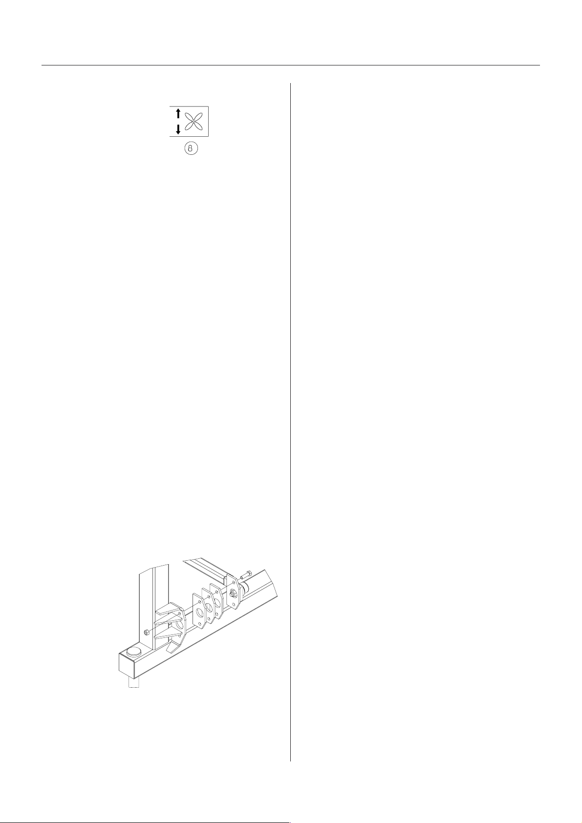
Electrical fan speed adjustment (if fitted)
Increasing of fan speed
Operation
Decreasing of fan speed
The max. Revolutions for the fan is 3100 r.p.m., which
will give full air speed of approx. 40 m/sec (90 mph).
The fan speed is indicated by the transmission working
pressure by means of a pressure gauge.
Conversion table between pressure and fan speed - see
section Air Technique
IMPORTANT! To avoid shock starting the fans always
set fan speed to 0 before engaging the P.T.O.
Boom supporBoom suppor
Boom suppor
Boom supporBoom suppor
The boom is equipped with two support wheels. When
spraying with low boom heights on bare ground or plants
in the first growth stage it is recommended to fold down
the support wheels. In later growth stages the wheels
should remain folded up.
IMPORTANT! When driving on public roads the support
wheels should be folded up and secured in order to keep
the machine overall width according to the regulations!
t wheelst wheels
t wheels
t wheelst wheels
T030-0004
Boom suspension sensitivityBoom suspension sensitivity
Boom suspension sensitivity
Boom suspension sensitivityBoom suspension sensitivity
The boom suspension will normally suit most conditions
and do not require any adjustment. The suspension will
keep the boom parallel to the ground and compensate
for uneven ground.
However, special conditions or situations can require the
suspension to react less or more slowly.
When the RH and LH
guide rods are
parallel to each
other (factory
setting) the boom
suspension will
react immediately,
and the boom will
move independently of the
trailer or tractor.
If the boom
should follow the movements or inclinations of the trailer
the guide rods should be inclined towards each other at
the rear.
T030-0005
Add 1-4 pcs. of 10 mm spacers as shown at each rod
until the desired function i reached.
GB 07 02
31
Page 32
Operation
OperOper
Oper
OperOper
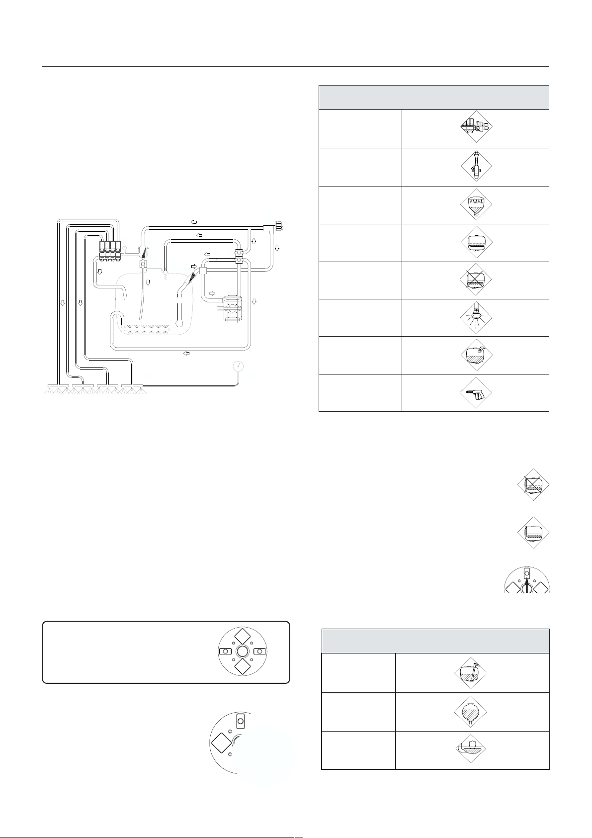
MANIFOLD SYMANIFOLD SY
MANIFOLD SY
MANIFOLD SYMANIFOLD SY
The MANIFOLD SYSTEM is located at the left side of
the sprayer and permits operation of the liquid system
from one position. The modular MANIFOLD system
facilitates the addition of up to two optional extras on the
pressure side and one extra on the suction side.
Function diagram - EVC (Standard)
aa
ting the liquid syting the liquid sy
a
ting the liquid sy
aa
ting the liquid syting the liquid sy
STEMSTEM
STEM
STEMSTEM
11
9
8
10
12
13
5
stemstem
stem
stemstem
1
7
4
6
2
3
14
T051-0007x
)erusserp(csidneerG-smargotciP
gninaelc-fleS
/retlif
tinugnitarepO
gnilliftsaF
ecived
RELLIFIDRAH
*
noitatigA
tuohtiW
noitatiga
gnihsulfknaT
elzzon
knatniamoT
nugyarpS
1. Suction filter
2. Suction manifold (black)
3. Pump
4. Pressure manifold (green)
5. Agitation
6. Without agitation (pressure equalisation)
7. HARDI MATIC
8. Return line (Self-cleaning filter)
9. Self-Cleaning Filter
10. Safety valve
11. Distribution valves
12. Return from Pressure Equalisation
13. Sprayer boom
14. Pressure gauge
Use ofUse of
Use of
Use ofUse of
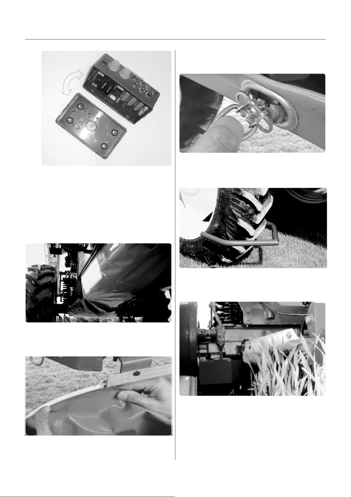
The following pictograms and colours are used for
visualizing the functions of the MANIFOLD valves:
MANIFOLD v MANIFOLD v
MANIFOLD v
MANIFOLD v MANIFOLD v
Green disc = Pressure valve
Black disc = Suction valve
Yellow disc = Self-cleaning filter
alvalv
alv
alvalv
e sye sy
e sy
e sye sy
stemstem
stem
stemstem
026
*Agitation
Normally, Agitation should be on but please refer to the
following rules of thumb:
1. Choose Without Agitation if a high level of
effervescence occurs in order to reduce the
amount of foam.
2. Choose Agitation when using powder
chemicals in order to avoid sedimentation.
3. Close the valve if spraying with a high
volume and it is impossible to achieve
sufficient pressure.
)noitcus(csidkcalB-smargotciP
morfnoitcuS
knatniam
A function is activated/opened
by turning the handle
towards the desired
function
32
Function
open
Closed
knatgnisniR
gnilliF
ecived
025
GB 08 04
Page 33
Operation
QuicQuic
QuicQuic
Quic
k rk r
k rk r
k r
efef
efef
ef
erer
erer
er
enceence
enceence
ence
)retlifgninaelc-fles(csidwolleY
The disc has two
positions; open
or closed
The valves and functions may vary from machine to
machine depending on optional equipment fitted. Only
the functions to be used must be open - Always close
remaining valves.
TT
o opero oper
T
o oper
TT
o opero oper
Turn the handle on a green pressure valve towards the
function desired
Turn the handle on a black suction valve towards the
desired function
Open or close yellow disc (self-cleaning filter)
Close all remaining valves by setting the handle(s)
on O
aa
te the sprte the spr
a
te the spr
aa
te the sprte the spr
aa
ying functions:ying functions:
a
ying functions:
aa
ying functions:ying functions:
Closed
Open
027
FF
illing ofilling of
F
illing of
FF
illing ofilling of
Water can be filled into the main tank in five ways:
1. Filled through tank lid.
2. Filled by diaphragm pump through a suction side fitted
filling device (optional extra) using normal pump
capacity directly to the tank.
3. Filled by diaphragm pump through a pressure side
fitted injector/venturi type Fast Filling Device (optional
extra) providing up to 3 times normal pump capacity.
4. Combination of 2 and 3.
5. Quick coupler for external filling
The tank should normally be filled 1/3 with water, before
adding the chemicals - always read instruction on
chemical container!
NOTE! Max. permitted tank contents:
w w
aa
terter
w
a
ter
w w
aa
terter
retaw,emuloV*sresilitrefdiuqil,emuloV
ledoM
ertiL lag.pmI lagSU ertiL lag.pmI lagSU
l002200224848.08545128.3746.865
l008200826162.93745128.3746.865
NOTE! If a MANIFOLD valve is too tight to operate - or
if it is too loose (= liquid leakage), the 3-way-valve needs
to be serviced. Please see the part Occasional mainte-
nance - Adjustment of 3-way-valve for further information.
Electrical operated MANIFOLD valves (if fitted)
One or more MANIFOLD valve(s) can be electrically
operated via a control box in the tractor cab. These can
only be operated manually when the power to the valve
motor is disconnected first.
Quick reference
A quick reference - consisting of two labels - is accompanying this book.
The labels are meant to be fitted to the frame near to
the MANIFOLD SYSTEM for easy in field operation of
the valves.
l002300234078.44800234078.448
l002400244298.801113238.0179.258
3.1ytivargcificepshtiwsresilitrefdiuqilnodesaB*
1. Filling through tank lid
Remove tank lid and fill water through strainer to prevent
rust or other particles to enter the tank.
An overhead tank can be used in order to obtain high
filling capacity.
It is recommended to use as clean water as possible for
spraying purposes.
WARNING! DO NOT LET FILLING HOSE ETC.
ENTER THE TANK. KEEP IT OUTSIDE THE
TANK, POINTING TOWARDS THE FILLING
HOLE.
chart 022
T060-0114
IF THE HOSE IS LEAD TO THE BOTTOM OF THE
TANK, AND THE WATER PUMP AT THE WATER
SUPPLY PLANT STOPS, CHEMICALS CAN BE SIPHONED BACK AND CONTAMINATE THE WATER
SUPPLY LINES.
GB 08 04
T021-0012
33
Page 34
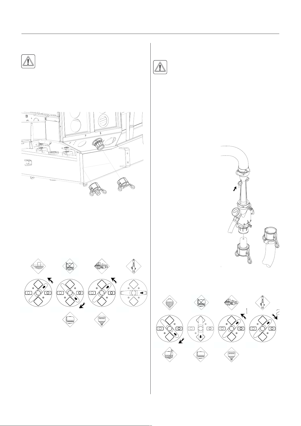
Operation
2. Suction Filling Device (if fitted)
WARNING! Avoid contamination or personal
injury. Do not open suction valve towards
Suction Filling Device unless pump is running and filling hose is connected. If this valve is
opened without pump running, liquid will stream out
of the MANIFOLD.
The Suction Filling Device is operated as follows:
T041-0013
A
B
1. Remove cover A, and connect suction hose B to
Suction Manifold.
2. Engage diaphragm pump and set P.T.O. revolutions at
540 r/min or 1000 r/min (depending on pump model)
3. Turn handle on Suction Manifold towards Filling
Device.
only to fill from closed reservoirs (mobile water tanks
etc.) to avoid contamination.
WARNING! If suction hose/filter is carried on the
sprayer during spraying, it can be contaminated
by spray drift which will be transferred to lake/
river when filling!
3. Fast Filling Device (if fitted)
The Fast Filling Device is operated as follows:
1. Ensure spray liquid tank contains at least 50 litres of
water.
2. Remove cover (A) and
connect suction hose (B).
3. Turn handle on Pressure
Manifold towards Fast
T041-0002
Filler. With the P.T.O. at
540 r/min or 1000 r/min
(depending on pump
model), the pressure
gauge should indicate
C
about 10 bar.
4. If water is not seen in the
transfer tube, prime by
turning valve (C).
5. Keep an eye on the liquid
B
level indicator.
6. Turn handle on Pressure
Manifold away from Fast
Filler to discontinue filling
A
process.
Black
Green Green
Green
T020-0003
4. The tank is now filled with water. Keep an eye on the
liquid level indicator.
5. Turn handle on Suction Manifold away from Filling
Device to discontinue filling process. Then disengage
pump.
6. Disconnect suction tube B and replace cover.
NOTE! Observe local legislation regarding use of Filling
Device. In some areas it is prohibited to fill from open
water reservoirs (lakes, rivers etc.). It is recommended
34
NOTE: Turn handle towards
-operating unit before turning away from Fast Filler in
order to avoid peak pressure blowing the safety valve!
Black Green Green Green
T020-0005
7. Disconnect suction tube (B) and replace cover.
GB 08 04
Page 35
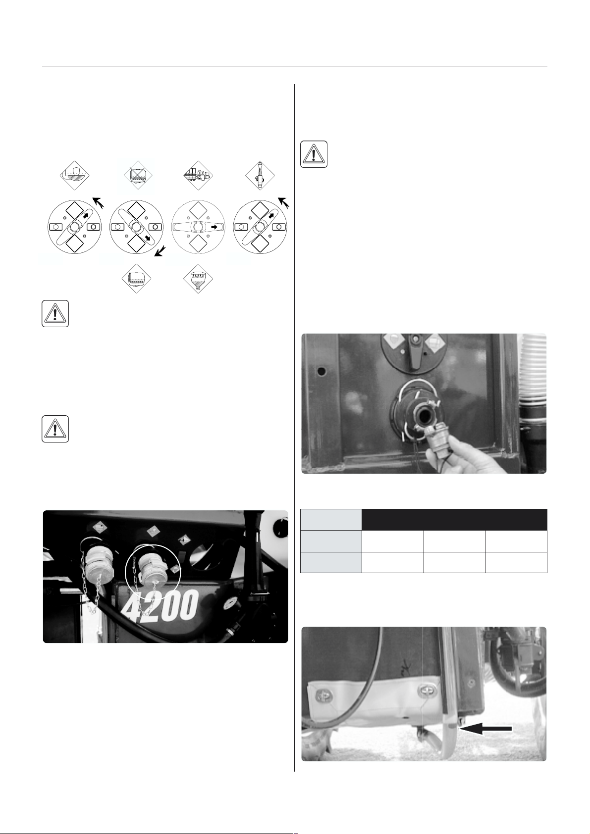
Operation
4. Filling device and Fast filling device used
simultaneously
The Filling Device and the Fast Filling Device can be
used simultaneously - this gives even bigger filling
capacity.
Black
WARNING: Do not leave the sprayer whilst
refilling the tank, and keep an eye on the level
gauge in order NOT to overfill the tank!
NOTE! Observe local legislation regarding use of Filling
Device. In some areas it is prohibited to fill from open
water reservoirs (lakes, rivers etc.). It is recommended
only to fill from closed reservoirs (mobile water tanks
etc.) to avoid contamination.
Green
Green
Green
T020-0004
5. Depending on the chemical in question, the Pressure
Manifold can be set on Agitation. If no agitation is
needed, this valve must be closed.
6. Engage the P.T.O. and start the pump.
WARNING: Do not leave the sprayer whilst
refilling the tank, and keep an eye on the level
gauge in order NOT to overfill the tank!
FF
illing ofilling of
F
illing of
FF
illing ofilling of
The rinsing tank is situated under the main tank. Only fill
this tank with clean water.
The rinsing tank is filled through the inlet, situated
beneath the Suction Manifold valves. Water can be
filled directly through the inlet - or through a socket
piece A (optional equipment) connected to a water hose.
rinsing tank (if rinsing tank (if
rinsing tank (if
rinsing tank (if rinsing tank (if
f f
itted)itted)
f
itted)
f f
itted)itted)
WARNING! If suction hose/filter is carried on the
sprayer during spraying, it can be contaminated
by spray drift, which will be transferred to lake/
river when filling!
5. Quick coupler for external filling
T060-0112
The quick coupler is operated as follows
1. Fit the external water hose to the quick coupler on the
trailer.
2. Close self-cleaning filter.
3. Turn handle on Pressure Manifold towards Main tank.
4. Turn handle on Suction Manifold towards Filling
device.
AA
A
AA
T060-0115
Rinsing tank capacity
ledoM ertiL .laG.pmI .laGSU
0082/00220627507
0024/0023064101021
A water level indicator (limpid hose with floating ball) is
situated beneath the platform.
028
GB 08 04
T060-0116
35
Page 36

Operation
FF
illing ofilling of
F
illing of
FF
illing ofilling of
The clean water tank is integrated in the platform and
has a capacity of 30 l. Access to the tank lid is possible
from the platform. Only fill this tank with clean water from
the well.
T060-0117
The water from this tank is for hand washing, cleaning of
clogged nozzles etc. The tap is centrally situated in near
reach from the MANIFOLD valves and is opened/closed
by a handle.
c c
lean wlean w
c
lean w
c c
lean wlean w
aa
ter tankter tank
a
ter tank
aa
ter tankter tank
Adjustment ofAdjustment of
Adjustment of
Adjustment ofAdjustment of
T020-0034x
T020-0018
EV EV
EV
EV EV
C operC oper
C oper
C operC oper
aa
ting unitting unit
a
ting unit
aa
ting unitting unit
WARNING! Although the clean water tank is only
filled with clean, it must never be used for drinking.
Before spraying, the EVC operating unit is adjusted
using clean water (without chemicals).
1. Choose the correct nozzle for the spray job by turning
the TRIPLET nozzle bodies. Make sure that all
nozzles are the same type and capacity. See the
Spray Technique book.
2. On-off switch A is activated against green.
3. All distribution valve switches V are activated against
green.
4. Pressure regulation switch C is activated until emer-
gency handle stops rotating (minimum pressure).
5. Put the tractor in neutral and adjust the P.T.O. and
thereby the number of revolutions of the pump corresponding to the intended travelling speed. Remember
the number of revolutions on the P.T.O. must be kept
between 300-600 rpm (pump 540 r/min) or 650-1100
rpm (pump 1000 r/min).
6. Pressure regulation switch C is activated until the
required pressure is shown on the pressure gauge.
36
Adjustment ofAdjustment of
Adjustment of
Adjustment ofAdjustment of
1. Close the first distribution valve switch V.
2. Turn the adjusting screw(s) until the pressure gauge
again shows the same pressure.
3. Adjust the other sections of the distribution valve in
the same way.
GB 08 04
pr pr
pr
pr pr
essuressur
essur
essuressur
e equalisae equalisa
e equalisa
e equalisae equalisa
tiontion
tion
tiontion
Page 37
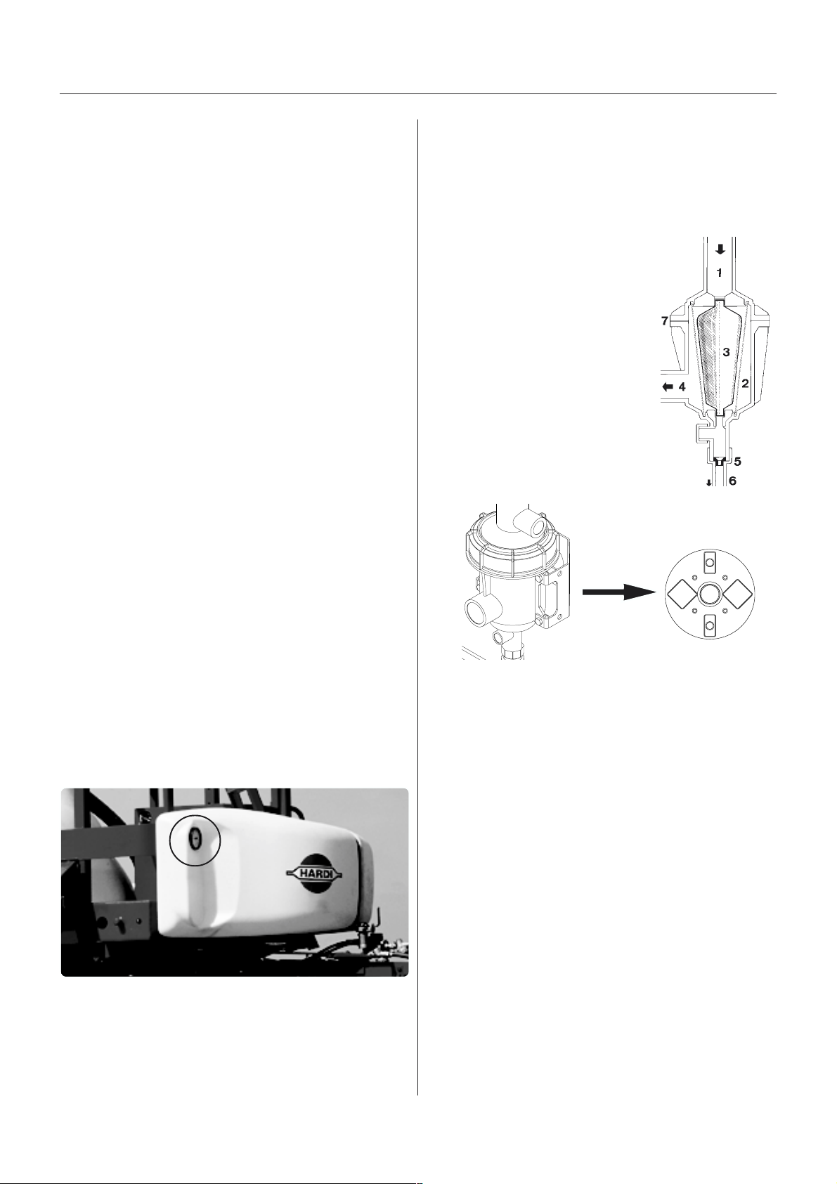
Operation
NOTE! HEREAFTER ADJUSTMENT OF PRESSURE
EQUALISATION WILL ONLY BE NEEDED WHEN:
1. YOU CHANGE TO NOZZLES WITH OTHER CAPACITI ES
2. THE NOZZLE OUTPUT INCREASES AS THE
NOZZLES WEAR
OperOper
aa
Oper
OperOper
In order to close the entire boom, switch ON/OFF A to
off position. This returns the pump output to the tank
through the return system.
The diaphragm Non-drip valves ensure instantaneous
closing of all nozzles.
In order to close one or more sections of the boom,
switch the relevant distribution valve V to off position.
The pressure equalisation ensures that the pressure
does not rise in the sections which are to remain open.
When the sprayer is put aside, the control box and the
multi plug must be protected against moisture and dirt.
A plastic bag may be used to protect the multi plug.
ting the contrting the contr
a
ting the contr
aa
ting the contrting the contr
ol unit while sprol unit while spr
ol unit while spr
ol unit while sprol unit while spr
aa
yingying
a
ying
aa
yingying
FF
ilterilter
ilter
ilterilter
ss
s
ss
leaning fleaning f
leaning f
leaning fleaning f
ilterilter
ilter
ilterilter
T059-0001
F
FF
All filters should always be used, and their function
checked regularly. The mesh size of the filter in use
should always be smaller than the flow average of the
nozzles used. Therefore, pay attention to the correct
combination of filters, mesh size.
Self-cSelf-c
Self-c
Self-cSelf-c
Operating diagram
1. From pump
2. Double filter screen
3. Guide cone
4. To operating unit
5. Replaceable restrictor
6. Return to tank
7. Screw-joint
The self-cleaning filter is operated
via the yellow MANIFOLD valve.
RR
emote premote pr
R
emote pr
RR
emote premote pr
The remote pressure gauge is integrated in the front
locker. This gauge measures the working pressure in the
boom tubes as close to the nozzles as possible. This
pressure reading will always be slightly lower than the
reading at the operating unit pressure gauge.
The outputs stated in the nozzle charts are always based
on the pressure measured at the nozzle.
Always adjust pressure when calibrating and spraying
according to readings at the Remote pressure gauge.
T060-0118
essuressur
essur
essuressur
e ge g
e g
e ge g
augaug
aug
augaug
e (ife (if
e (if
e (ife (if
f f
itted)itted)
f
itted)
f f
itted)itted)
T020-0006
IMPORTANT! The yellow MANIFOLD valve should
normally be open, but must be closed in the following
cases:
1. If rinsing with water from the rinsing tank and a
quantity of spray liquid still remains in the main tank
(otherwise the spray liquid will be diluted).
2. If opening the self-cleaning filter and a quantity of
spray liquid still remains in the main tank (otherwise
there is a risk that spray liquid will flow out).
Choice of correct restrictor
It is important to have a large flow through the filter. This
is achieved by choosing the restrictor size in relation to
the liquid consumption of the spray boom.
4 restrictors are supplied. Use the green one (largest
orifice) first.
GB 08 04
37
Page 38
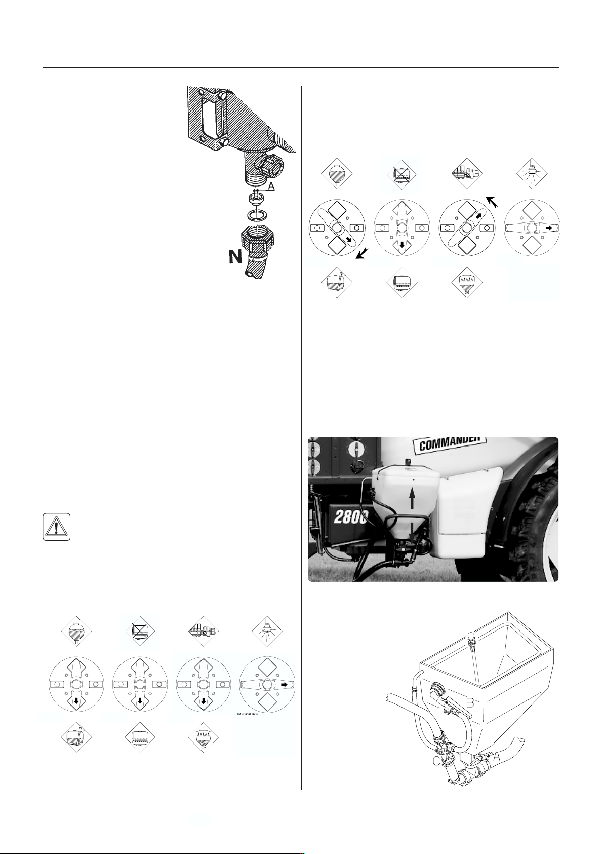
Operation
The hose N is demounted at the
self-cleaning filter, the restrictor
is put in the hose and the hose
is mounted again. If the required working pressure cannot
be obtained, the restrictor is too
large. Choose a smaller restrictor. Start
with a black one, then a white and finally a
red one.
When cleaning the filter remove hose N
and the hose at the safety valve, and
check there are no residue.
Standard filter size is 80 mesh. Sizes of
50 and 100 mesh are available and can
be changed by opening the filter top,
and replace the strainer.
Check the O-rings before reassembling the filter and
replace if damaged.
FF
illing ofilling of
F
illing of
FF
illing ofilling of
Chemicals can be filled in the tank in two ways:
1. Through tank lid.
2. By means of HARDI FILLER chemical filling device.
c c
hemicalshemicals
c
hemicals
c c
hemicalshemicals
T020-0020
4. Add the chemicals through the main tank hole.
5. When the spray liquid is well mixed, turn handle on
the Pressure Manifold towards Spraying position.
Keep P.T.O. engaged so the spray liquid is continuously agitated until it has been sprayed on the crop.
Black
2. F2. F
illing billing b
2. F
illing b
2. F2. F
illing billing b
inductorinductor
inductor
inductorinductor
To get access to the HARDI FILLER, grab the handle
and drag the HARDI FILLER the whole way down. Due
to the spring loaded suspension, it will stay in this
position. After use, it is pushed the whole way up again.
Green Green Green
y HARDI FILLER cy HARDI FILLER c
y HARDI FILLER c
y HARDI FILLER cy HARDI FILLER c
hemicalhemical
hemical
hemicalhemical
1. F1. F
illing thrilling thr
1. F
illing thr
1. F1. F
illing thrilling thr
The chemicals are filled through the tank lid - Note
instructions on the chemical container!
WARNING! Be careful not to slip or splash
chemicals when carrying chemicals up to the
tank lid!
1. Make sure the EVC is switched off.
2. Set the MANIFOLD valves to correct position. Black
valve Suction from main tank, green valve towards
Agitation
Black
3. Engage the pump and set P.T.O. revolutions to 540
r/min or 1000 r/min (depending on pump model).
ough tank lidough tank lid
ough tank lid
ough tank lidough tank lid
Green
Green Green
T060-0119
Filling of Liquid chemicals
1. Fill the main tank at
least 1/3 with water
(unless something else is
stated on the
chemical
container
label). See
section Filling
of water.
2. Turn the handle
at the Suction
Manifold towards Main
tank . Turn green valve
T042-0001
38
GB 08 04
Page 39
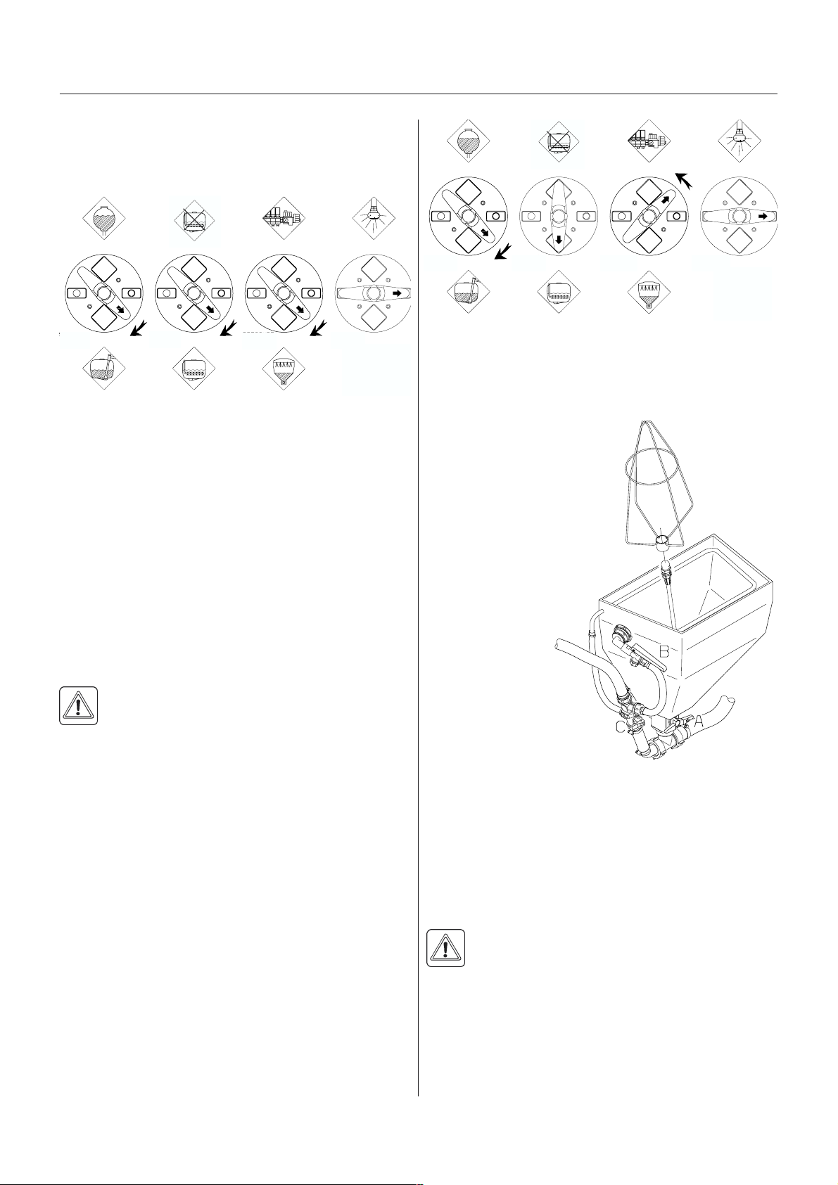
Operation
towards HARDI FILLER and the other green valve
towards agitation. Close remaining valves.
3. Check that bottom valve A at the FILLER is closed.
Black Green Green Green
4. Engage the pump and set P.T.O. speed at 540 r/min
or 1000 r/min (depending on pump model).
5. Open FILLER lid.
6. Measure the correct quantity of chemical and fill it
into the hopper.
NOTE! The scale in the hopper can only be used if the
sprayer is parked at level ground! It is recommended to
use a measuring jug for best accuracy.
7. Open the bottom valve A and the chemical is trans-
ferred to the main tank.
8. If the chemical container is empty it can be rinsed by
the container rinsing device (if fitted). Place the
container over the multi-hole nozzle and press the
lever B.
WARNING! Do not press lever B unless the
multi-hole nozzle is covered by a container to
avoid spray liquid hitting the operator.
IMPORTANT! Rinsing device uses spray liquid to rinse
containers for concentrated chemicals. Always rinse the
chemical containers with clean water several times until
they are clean before disposal.
9. Engage the hopper rinsing device by opening valve C.
10. Close valve C again when the hopper is rinsed.
IMPORTANT! The hopper rinsing device is using spray
liquid for rinsing the hopper for concentrated chemical!
The FILLER must always be cleaned together with the
rest of the sprayer when the spray job is done.
11.Clos e val ve A and the FILLER lid again.
12. When the spray liquid is well mixed, turn handle on
the Pressure Manifold towards Spraying position.
Keep P.T.O. engaged so the spray liquid is continuously agitated until it has been sprayed on the crop.
Black Green
Green
Green
Filling of Powder chemicals
1. Fill the main tank at least 1/2 with water (unless something else is stated on the
chemical container label).
See section Filling of
water.
2. Turn the handle at the
Suction Manifold
towards Main tank
T042-0002
and green valve
towards Agitation.
Turn the handle at
the Pressure Manifold towards
HARDI FILLER.
Close remaining
valves.
3. Engage the pump
and increase
P.T.O. speed to
540 r/min or 1000 r/
min (depending on
pump model).
4. Open the bottom valve A at
the FILLER. Open FILLER lid.
5. Engage the hopper rinsing device by opening valve C.
6. Measure the correct quantity of chemical and sprinkle
it into the hopper as fast as the rinsing device can
flush it down.
7. If the chemical container is empty it can be rinsed by
the container rinsing device (if fitted). Fit the bag
bracket and place the powder bag over the multi-hole
nozzle and press the lever B.
WARNING! Do not press lever B unless the
multi-hole nozzle is covered by a container to
avoid spray liquid hitting the operator.
IMPORTANT! Rinsing device uses spray liquid to rinse
containers for concentrated chemicals. Always rinse the
chemical containers with clean water several times until
they are clean before disposal.
9. Close valve C again when the hopper is rinsed.
GB 08 04
39
Page 40
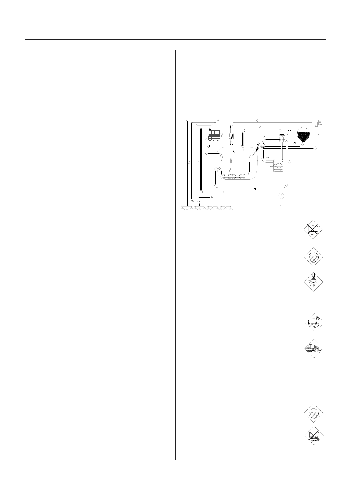
Operation
IMPORTANT! The hopper rinsing device is using spray
liquid to rinse the hopper for concentrated chemical. The
FILLER must always be cleaned together with the rest of
the sprayer when the spray job is done.
10.Close valve A and the FILLER lid again.
11.When the spray liquid is well mixed, turn handle on
the Pressure Manifold towards Spraying position.
Keep P.T.O. engaged so the spray liquid is continuously agitated until it has been sprayed on the crop.
Use of rinsing tank and rinsingUse of rinsing tank and rinsing
Use of rinsing tank and rinsing
Use of rinsing tank and rinsingUse of rinsing tank and rinsing
nozzles (ifnozzles (if
nozzles (if
nozzles (ifnozzles (if
The incorporated rinsing tank can be used for two
different purposes.
A. In-field diluting of remaining spray liquid residue in the
spraying circuit for spraying the liquid in the field, before
cleaning the sprayer.
1. Empty the sprayer as much as possible.
Turn the green pressure valve towards No
Agitation and spray till air comes out of all
nozzles.
2. Remove the tank filter basket.
3. Turn black suction valve towards Rinsing
tank.
f f
itted)itted)
f
itted)
f f
itted)itted)
T055-0025x
4. Turn green pressure valves towards Rinsing nozzle (if fitted).
5. Engage and set the pump at appro.. 300
r.p.m.
6. When rinsing water corresponding to appro.. 10
times the spray liquid residue (see paragraph
Technical Residue) is used, turn black
suction valve towards Suction from main
tank and operate all valves, so all hoses and
components are rinsed.
7. Turn green pressure valve back to Operating unit and spray liquid in the field you have
just sprayed.
8. Repeat point 3-7 until the rinsing tank is empty.
B. Rinsing the pump, operating unit, spray lines, etc. in
case of stop in spraying before main tank is empty (e.g.
beginning rain etc.).
1. Close Self-cleaning filter (yellow valve).
2. Turn black suction valve towards Rinsing
tank.
3. Turn green pressure valve towards No
Agitation
40
4. Engage the pump and spray water from rinsing tank in
the field until all nozzle tubes/nozzles are flushed with
GB 08 04
Page 41
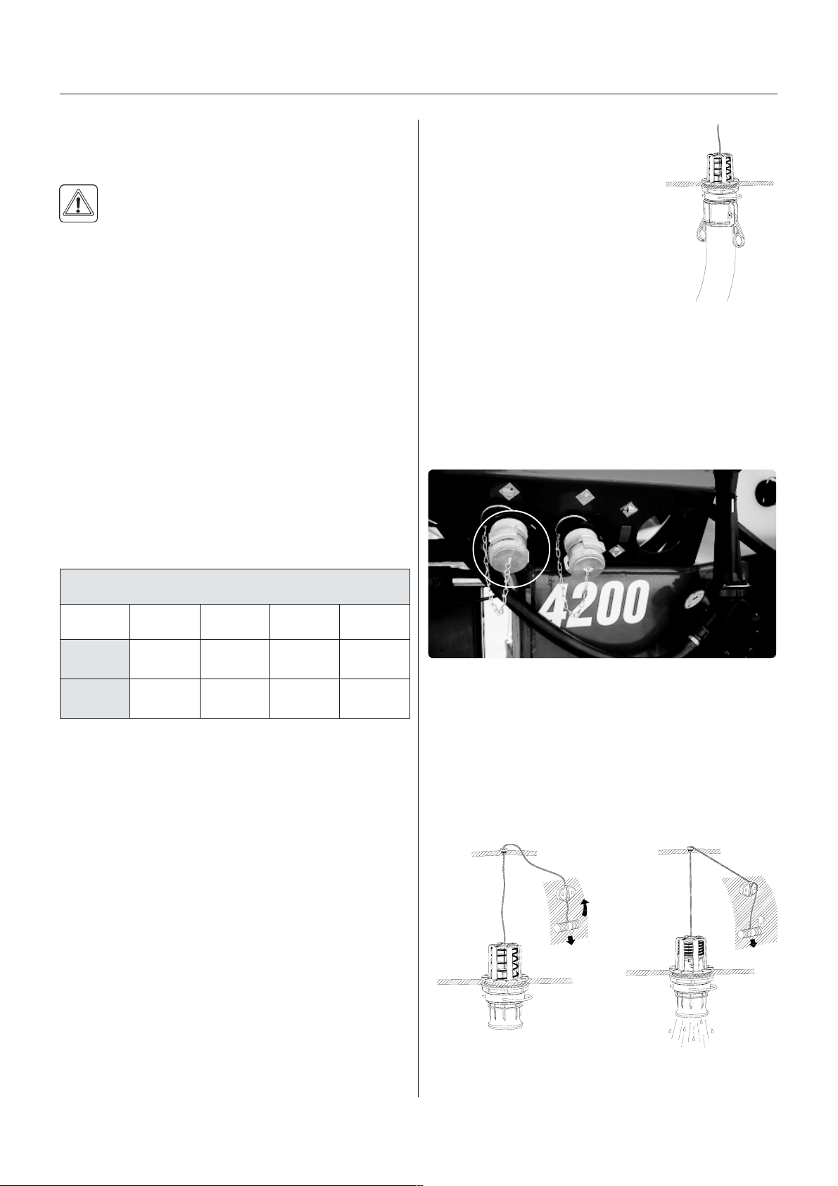
Operation
clean water.
5. Disengage pump again.
6. Open Self-cleaning filter again.
WARNING! The rinsing nozzles cannot always
guarantee a 100% cleaning of the tank. Always
clean manually with a brush afterwards, especially if crops sensitive to the chemical just sprayed are
going to be sprayed afterwards!
TT
ecec
hnical Rhnical R
T
ec
hnical R
TT
ecec
hnical Rhnical R
Inevitably a quantity of spray liquid will remain in the
system. It cannot be sprayed properly on the crop, as
the pump takes in air when the tank is about to be
empty.
This Technical Residue is defined as the remaining liquid
qty. in the system as the first clear pressure drop on the
pressure gauge is read.
esidueesidue
esidue
esidueesidue
DrDr
aining a raining a r
Dr
aining a r
DrDr
aining a raining a r
Using the drUsing the dr
Using the dr
Using the drUsing the dr
If draining a residue, e.g. liquid
fertilisers into a reservoir, a snap
coupler with hose can rapidly be
connected to the drain valve, and the
liquid can be let safely out.
Using the suction quicUsing the suction quic
Using the suction quic
Using the suction quicUsing the suction quic
1. Connect the hose to the suction quick coupler on the
trailer (pressure).
2. Turn the green valve towards External tank.
3. Turn the black valve towards Suction from main tank
and close Self-cleaning filter (yellow valve).
4. Engage the P.T.O to start the pump.
esidueesidue
esidue
esidueesidue
ain vain v
alvalv
ain v
alv
ain vain v
alvalv
ee
e
ee
k couplerk coupler
k coupler
k couplerk coupler
T020-0023
ertil,eudiseR
0082/00220024/00230082/00220024/0023
elbatuliD
1
eudiser
latoT
2
eudiser
1) Residue in main tank, possible to dilute with water from rinsing
tank
2) Total residue in tank and spraying circuit on standard sprayer.
Variations due to different ground inclinations etc.
The dilutable residue must be diluted 10 times with clean
water and sprayed to the crop just sprayed before
cleaning the sprayer - See paragraph Cleaning.
----
----
024
T060-0112
OperOper
Oper
OperOper
Main tankMain tank
Main tank
Main tankMain tank
Pull the string at left hand side of the tank to open the
drain valve. The valve is spring-loaded but can be kept
open by pulling the string out and upwards in the Vshaped slit.
aa
tion oftion of
a
tion of
aa
tion oftion of
the dr the dr
the dr
the dr the dr
ain vain v
ain v
ain vain v
alvalv
alv
alvalv
eses
es
eses
T020-0021
T020-0022
To release and close the drain valve again pull the string
downwards and the valve will close automatically.
GB 08 04
41
Page 42

Operation
Rinsing tankRinsing tank
Rinsing tank
Rinsing tankRinsing tank
To avoid algae developing in the rinsing tank always
drain the rinsing tank when the sprayer is not in use for a
long period.
SafSaf
ety prety pr
Saf
ety pr
SafSaf
ety prety pr
PP
erer
sonal prsonal pr
P
er
sonal pr
PP
erer
sonal prsonal pr
Dependant on which type of chemical used, the
following protective clothing/equipment should be used:
ecautionsecautions
ecautions
ecautionsecautions
Always be careful when working with crop
protection chemicals!
otectionotection
otection
otectionotection
SprSpr
Spr
SprSpr
aa
a
aa
y Ty T
y T
y Ty T
ecec
hnique - see sehnique - see se
ec
hnique - see se
ecec
hnique - see sehnique - see se
parpar
par
parpar
aa
te bookte book
a
te book
aa
te bookte book
Gloves
Waterproof boots
Headgear
Respirator
Safety goggles
Chemical resistant overall
This equipment should be worn to avoid contact with the
chemicals.
Protective clothing/equipment should be used
when preparing the spray liquid, during the spray
ing work and when cleaning the sprayer. Also
follow the recommendations on the chemical
label.
It is always advisable to have clean water avail
able, especially when filling the sprayer with the
chemical.
Always clean the sprayer carefully and immedi
ately after use.
Do not mix different chemicals in the tank.
42
Always clean the sprayer before changing to
another chemical.
GB 08 04
Page 43
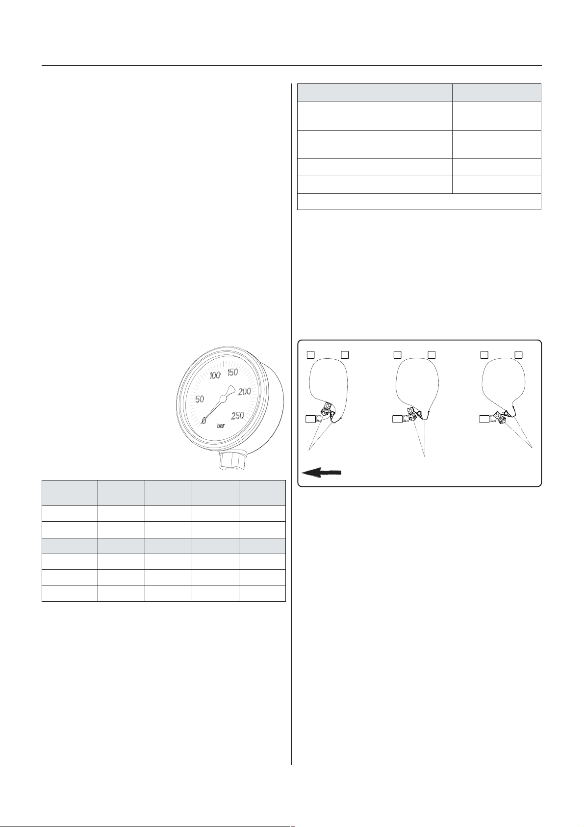
Air Technique
Air tecAir tec
Air tec
Air tecAir tec
With TWIN air assistance energy is added to the spray
droplets to improve control with the spray liquid .
This way TWIN makes it possible to:
carry the spray droplets safely to the target and in-
crease plant deposit
minimize off-target deposit due to wind drift or loss on
the ground
open the crop and obtain good penetration even with a
low volume rate
ensure a high coverage.
Air speed / Air vAir speed / Air v
Air speed / Air v
Air speed / Air vAir speed / Air v
The fan speed is infinitely variable and can produce from
0 to 35 m/s (78 mph) air speed at the air outlet. This
equals from 0 to 2000 m3 air/m boom/hour
(3.872 CFM/A boom/hour).The air speed must be
adjusted to the spray job
BlowBlow
Blow
BlowBlow
The oil flow determines the air
speed from the blowers. The
oil flow can be observed on
the pressure gauge (0-250
bar).
hniquehnique
hnique
hniquehnique
olumeolume
olume
olumeolume
er adjustmenter adjustment
er adjustment
er adjustmenter adjustment
bojyarpS ecnatsissariA
/noitategevwol/dnuorgeraB
porcworegatsylrae
porcafopotehtylnogniyarpS
*taehwnigniyarpsrae.g.e
*porcneponinoitartenePhgiH/muideM
*porcesnedninoitartenePhgihyreV/hgiH
AngAng
ling ofling of
Ang
ling of
AngAng
ling ofling of
The main purpose of the TWIN angling system is to
counteract for the negative influence which wind direction and driving speed have on the quality of the spray
job. Further the co-angling af air and liquid can help
opening dense crops for better penetration
The TWIN FORCE air system can be set at any angle
from 40° forward to 30° back (defined by the air stream).
air and liquid. air and liquid.
air and liquid.
air and liquid. air and liquid.
woL
repapevitisnesretawhtiwdekcehcebnaC*
muideM/woL
019
The colour codes of the
gauge refer to air speed
produced at certain pressure
ranges.
ecnatsissariA
level
)s/m(deepsriA
.m.p.rnaF
edocruoloC eulB neerG egnarO deR
m81mooB
m12-02mooB
m82-42mooB
Pressure in bar
When booms are half-folded, reduce r.p.m. or pressure
with 25% to obtain the same performance.
The following table gives a rough guideline of the air
assistance needed for different crop conditions.
)L(woL )M(muideM )H(hgiH
01-502-0103-0253-03
0001-0040091-00010072-00910013-0072
04-0257-04521-57081-521
05-5209-05051-09002-051
07-03041-07091-041042-091
T119-0001x
)HV(
Driving direction
hgihyreV
Adjusting the air assistanceAdjusting the air assistance
Adjusting the air assistance
Adjusting the air assistanceAdjusting the air assistance
The air speed and angling must always be adjusted
individually for each spray job and the given weather
conditions.
It is always a good idea to get used to a new sprayer out
in a field with only water in the tank, on this occasion the
following routine for air adjustment should be practised:
018
1. Start with the air vertical
2. Set the air speed ............... A
3. Find the best angling ......... B
4. Readjust the air ..................A
IMPORTANT! Fine turning of air speed and angling will
often be necessary all through the spraying job.
T030-0002
It is easiest to find the best air setting to reduce drift
when the sun is low and behind the boom (backlight).
These conditions make the drift more visible.
GB 09 01
43
Page 44

Air Technique
A Setting of air speed, rules of thumb
Step 1: Find the range of air speeds that can control
drift:
1.Start with the air setting at zero and keep increasing
the air speed just to the point where you can see that
the drift cloud is minimised - note minimum setting.
2.Then increase the air speed until you see drift again note maximum setting.
3.Now you know the range of air speeds that can be
used with minimum drift.
Bare ground / low crop
The range of air speeds is usually very small.
Taller crop
The taller the crop the wider the range of air speeds that
can reduce drift.
At higher wind speeds
More air is needed on the sprayer and it is advisable
to drive more slowly and use minimum boom height
(40 cm)/(16 in).
NOTE! Too high air speed over bare ground/low crop
can cause reflection of the spray liquid and leave dust
on the leaves, which can again reduce the effect of the
plant protection product.
Step 2: Set the optimal air speed within possible the
range mentions above.
Conditions Air speed recommendations
Bare ground / low crop:Use maximum air within the
possible range
Taller crop: Deeper crop penetration
requires more air on the
sprayer (if you are in doubt
check with water sensitive
paper).
Forward speed: Higher forward speeds require
more air on the sprayer.
Volume rate: Lower volume rates require
more air assistance to avard
drift.
B Angling of air and liquid, rules of thumb
To control wind drift the influence of wind speed and
wind direction as well as the horizontal air current
around the boom due to forward speed must be minimised. Because it is a sum of two forces with variable
direction and size that we have to counteract for, the
following can only be very rough guidelines.
NOTE! Often it will be necessary to drive with two
different anglings, so the angling is changed when
changing driving direction after turning at the headland.
Wind direction Angle / air speed
Head wind: Angle forward
Down wind: Angle back (if the forward speed is
higher than the wind speed: angle
forward)
Side wind /
No wind: Angle vertical or back. Only high
forward speeds may require forward
angling.
Crop condition Angle / air speed
Bare ground/
low vegetation: Low air speed and angling back will
often be the best setting to avoid
reflection of spray liquid.
Dense crop: The angling feature is ideal to
help opening the canopy and im
prove penetration. If you follow the
crop movement as you are varying
the angling you will find that at certain
settings the crop will open more for
penetration.
If wind speed, wind direction or for some reason forward
speed changes during spraying the optimum angling is
likely to change too. Be aware that with certain combinations of air speed and angling you can close or flatten
the crop and make penetration impossible - follow the
crop movement intensively especially when setting the
air assistance and keep an eye on the crop all through
the application.
NOTE!
It is most important that the sprayer operator is familiar
with the above rules of thumb before using the TWIN
sprayer
All volume rates, pressures and air adjustments stated
in the following tables are, of course, guiding. Special
conditions regarding climate, crop quality, spraying time
and applied chemical can change the procedure. The
tables are showing practice in northern Europe, and
conditions may be very different in other countries. If you
want some local advice you are very welcome to contact
the TWIN application expert at the HARDI importer or
daughter company in your country
The volume rate can generally be reduced to half of
what is applied with a conventional sprayer, but with a
minimum of 50-60 l/ha at 7-8 km/h (5.5-6.5 GPA at 4.5-5
44
GB 09 01
Page 45

Air Technique
mph. Exceptions are of course liquid fertiliser and
herbicides whose selectivity is based large droplets that
will only stick to the weeds
Low drift nozzles can also be fitted on a TWIN sprayer
and help reduce drift even further
If there is a detailed spraying instruction on the chemical label regarding drop size, spray pressure, spray
volume rate etc. this should be followed. Enclose 1 bag
of water sensitive paper and instruction of how to use
with all TWIN sprayers.
h/mk8deepsrotcarT-yelraBgnirpS
ksatyarpS
gniyarps.breH4-257011-510-F1.2M/L
gniyarpstaodliW5-3001011-510-F6.3M
gniyarpsedicignuF.17-505011-10-F1.2M
gniyarpssdihpA1.01-7001011-510F6.3H
egatshtworG
elacssekeeF
ah/l
WW
aa
ter sensitivter sensitiv
W
a
ter sensitiv
WW
aa
ter sensitivter sensitiv
e pae pa
e pa
e pae pa
perper
per
perper
USE WATER SENSITIVE PAPER TO HELP FIND THE
BEST AIR SETTING.
Some time spent in different types of crops with clean
water in the tank and some water sensitive paper will be
valuable experience for the future work with your TWIN
sprayer. The paper can be cut into smaller pieces (to
simulate the target) and fixed with double sided tape at
relevant places in the crop. Then spray with pure water
and check the blue spots (droplets) on the paper. This
way you can test different spraying techniques. Water
sensitive paper is available at your local HARDI dealer,
part No. 893211
etaremuloV
OSIelzzoN raberusserP gnittesriA
noitalugerhtworG1.01-805011-10-F1.2H
gniyarpsedicignuF.21.01-9001011-510-F6.3H
gniyarps.breH
ssarghcuoC
syad01tsetaL
tsevraherofeb
05011-10-F1.2H/M
h/mk6deepsrotcarT-seotatoP
ksatyarpS egatshtworG
gniyarps.breHecnegreme-erP57011-10-F7.2L
gniyarps.breHecnegreme-tsoP57011-10-F7.2*M/L
gniyarps.breHhgihmc51mluaH57011-10-F7.2M
sesaesiD
)thgilbeotatop(
noitacciseD
tsetalgniyarps.1
1yluJ
srebutehtnehW
ezisehtevah
deriuqer
etaremuloV
ah/l
051011-20-F6.2)HV(H
002011-30-F1.2)HV(H
OSIelzzoN raberusserP gnittesriA
tsevraherofebskeew2litnulavretnisyad01htiwdetaeperebottnemtaertemaS
009 011
NOTE! All volume rates, pressures and air suggestions indicated in these tables are only guiding. Special conditions regarding climate, quality
of the crop, spraying time and chemicals applied (burning) may partially change the procedure.
* NOTE! If dust is deposited on leaves the air speed must be reduced.
GB 09 01
45
Page 46

Air Technique
h/mk8deepsrotcarT-taehWretniW
ksatyarpS
-erpgniyarps.breH
ecnegreme
-tsopgniyarps.breH
ecnegreme
nmutuaedicignuF3-257011-510-F1.2M
gnirpsgniyarps.breH457011-510-F1.2M
noitalugerhtworG457011-510-F1.2M
topseyE6-557011-510-F1.2M
fael,edicignuf.1
esaesid
noitalugerhtworG9-857011-510-F1.2H/M
gniyarpssdihpa.19-857011-510-F1.2H/M
fael,edicignuf.2
esaesid
gniyarpssdihpa.25.01-0105011-10-F1.2L
rae,edicignuF
sesaesid
gniyarps.breH
ssarghcuoC
htworG
elacssekeeF
057011-510-F1.2L
2-1001011-510-F6.3*M/L
757011-510-F1.2M
01-957011-510-F1.2H/M
11-0105011-10-F1.2L
syad01tsetaL
tsevraherofeb
etaremuloV
ah/l
05011-10-F1.2H/M
OSIelzzoN raberusserP gnittesriA
010 012
h/mk8deepsrotcarT-eyR
ksatyarpS
,gniyarps.breH
epytlaudiser
,gniyarps.breH
ecnegreme-tsop
edicignufnmutuA3-257011-510-F1.2M
gnirps,gniyarps.breH457011-510-F1.2M
noitalugerhtworG6-5001011-510-F6.3M
topseye,edicignuF6-5001011-510-F6.3H/M
esaesidfael,edicignuF8-7001011-510-F6.3H/M
noitalugerhtworG9-857011-510-F1.2M
gniyarpsedicitcesnI5.01-0157011-510-F1.2M
gniyarps.breH
ssarghcuoC
egatshtworG
elacssekeeF
057011-510-F1.2L
2-1001011-510-F6.3*M/L
erofebsyad01
tsevrah
etaremuloV
ah/l
57011-510-F1.2H/M
OSIelzzoN raberusserP gnittesriA
NOTE! All volume rates, pressures and air suggestions indicated in these tables are only guiding. Special conditions regarding climate, quality
of the crop, spraying time and chemicals applied (burning) may partially change the procedure.
* NOTE! If dust is deposited on leaves the air speed must be reduced.
46
GB 09 01
Page 47

Air Technique
h/mk8deepsrotcarT-epaRretniW
ksatyarpS
gniyarps.breHgnillird-erP57011-510-F1.2L
gniyarps.breHgnillird-tsoP001011-510-F6.3*L
laerecreetnuloVecnegreme-erP001011-510-F6.3L
stsePecnegremetA57011-510-F1.2*M/L
laerecreetnuloVegatsfael4001011-510-F6.3M
stseP
dopacissarb,stseP
egabbacdnaegdim
liveewdees
stsePgnirewolflluF001011-510-F6.3H
edicignuF
hcuoc,gniyarps.breH
noitaccised+ssarg
egatshtworG
elacssekeeF
tnalp/selteeb3-2
dubninehw
fogninnigeB
gnirewolf
dnagnirewolflluF
gnisaeclitnu
erofebskeew2
tsevrah
etaremuloV
ah/l
57011-510-F1.2M
001011-510-F6.3H/M
001011-510-F6.3HV/H
001011-20-F1.2HV/H
OSIelzzoN raberusserP gnittesriA
h/mk8deepsrotcarT-)wolley(saeP
013 014
ksatyarpS
gniyarps.breHecnegreme-erP57011-510-F1.2L
naebdnaaep(stseP
)spirht+liveew
gniyarps.breHhgihmc5-2001011-20-F1.2M
gniyarpsedicignuF
dnafael+dluomyerg(
aepdnatopsdopmets
)liveew
gniyarpsedicignuF
aep+dluomyerg(
)liveew
gniyarpssdihpA
hcuoc,gniyarps.breH
ybnoitaccised+ssarg
edicibrehcimetsys
tcatnocybgnirehtiW
edicabreh
egatshtworG
elacssekeeF
ecnegreme-tsoP001011-20-F1.2L
gnirewolfotroirP001011-20-F1.2H/M
retalsyad41001011-20-F1.2H
litnugnirewolftA
gnisaec
erofebskeew4-2
tsevrah
erofebskeew4-2
tsevrah
etaremuloV
ah/l
001011-20-F1.2M
001011-510-F6.3H
051011-20-F6.4H
OSIelzzoN raberusserP gnittesriA
NOTE! All volume rates, pressures and air suggestions indicated in these tables are only guiding. Special conditions regarding climate, quality
of the crop, spraying time and chemicals applied (burning) may partially change the procedure.
* NOTE! If dust is deposited on leaves the air speed must be reduced.
GB 09 01
47
Page 48

Air Technique
h/mk8deepsrotcarT-epaRgnirpS
ksatyarpS
gniyarps.breHgnillird-erP57011-510-F1.2L
gniyarps.breHgnillird-tsoP57011-510-F1.2L
stsePecnegremetA57011-510-F1.2*L
gniyarps.breH
seiceps-fael-daorb
gniyarps.breH
suonodelytoconom
seiceps
elteebmossolb,stseP
dopacissarb,stseP
egabbacdnaegdim
liveewdees
dopacissarb,stseP
egabbacdnaegdim
liveewdees
edicignuFgnirewolffodnetA001011-510-F6.3HV/H
hcuoc,gniyarps.breH
noitaccised+ssarg
1
egatshtworG
elacssekeeF
sevaeleurt4-3001
sevaeleurt4001011-510-F6.3M
tnalp/elteeb1
dubninehw
gninnigeB
gnirewolf
gnirewolflluftA57011-510-F6.3H
erofebskeew2
tsevrah
etaremuloV
ah/l
1
57011-510-F1.2M
57011-510-F1.2H/M
001011-510-F6.3HV/H
OSIelzzoN raberusserP gnittesriA
011-20-F1.2M/L
ah/l051etarretawesu,ximknatani)nizanayC(xedalBdna)dilarypolC+lyhte-nilozaneB(xolasaneBetaresodllufgniylppafI
014
NOTE! All volume rates, pressures and air suggestions indicated in these tables are only guiding. Special conditions regarding climate, quality
of the crop, spraying time and chemicals applied (burning) may partially change the procedure.
* NOTE! If dust is deposited on leaves the air speed must be reduced.
48
GB 09 01
Page 49

Maintenance
Maintenance - rMaintenance - r
Maintenance - r
Maintenance - rMaintenance - r
In order to derive full benefit from the sprayer for many
years the following service and maintenance program
should be followed.
IMPORTANT! Always read the individual paragraphs.
Read instructions for service/maintenance jobs carefully
before starting on the job. If any portion remains unclear
or requires facilities which are not available, then for
safety reasons please leave the job to your HARDI
dealers workshop.
Cleaning the sprCleaning the spr
Cleaning the spr
Cleaning the sprCleaning the spr
Guidelines
1. Read the whole chemical label. Take note of any
particular instructions regarding recommended
protective clothing, deactivating agents, etc. Read the
detergent and deactivating agent labels. If cleaning
procedures are given, follow them closely.
2. Be familiar with local legislation regarding disposal of
pesticides washings, mandatory decontamination
methods, etc. Contact the appropriate department,
e.g. Dept. of Agriculture.
3. Pesticide washings can usually be sprayed out on a
soakaway. This is an area of ground that is not used
for cropping. You must avoid seepage or runoff of
residue into streams, water courses, ditches, wells,
springs, etc. The washings from the cleaning area
must not enter sewers. Drainage must lead to an
approved soakaway.
4. Cleaning starts with the calibration, as a well calibrated sprayer will ensure the minimal amount of
remaining spray liquid.
ules ofules of
ules of
ules ofules of
aa
yy
erer
a
y
er
aa
yy
erer
thumb thumb
thumb
thumb thumb
Cleaning the tank
1. Dilute remaining spray liquid in the tank with at least
10 parts of water and spray the liquid out in the field
you have just sprayed - See paragraph Use of rinsing
tank and rinsing nozzles.
NOTE: It is advisable to increase the forward speed
(double if possible) and reduce the pressure to 1.5
bar (20 psi).
2. Select and use the appropriate protective clothing.
Select detergent suitable for cleaning and suitable
deactivating agents if necessary.
3. Rinse and clean sprayer and tractor externally. Use
detergent if necessary.
4. Remove tank and suction filters and clean. Be careful
not to damage the mesh. Replace suction filter top.
Replace filters when the sprayer is completely clean.
5. With the pump running, rinse the inside of the tank.
Remember the tank roof. Rinse and operate all
components and any equipment that has been in
contact with the chemical.
Before opening the distribution valves and spraying
the liquid out, decide whether this should be done in
the field again or on the soakaway.
6. After spraying the liquid out, stop the pump and fill at
NOTE! If a cleaning procedure is given on the chemi cal label, follow it closely.
1
least
/5 of the tank with clean water. Note that some
chemicals require the tank to be completely filled.
Add appropriate detergent and/or deactivating agent,
e.g. washing soda or Triple ammonia.
5. It is good practice to clean the sprayer immediately
after use and thereby rendering the sprayer safe and
ready for the next pesticide application. This also
prolongs the life of the components.
6. It is sometimes necessary to leave spray liquid in the
tank for short periods, e.g. overnight, or until the
weather becomes suitable for spraying again. Unauthorised persons and animals must not have access
to the sprayer under these circumstances.
7. If the product applied is corrosive, it is recommended
to coat all metal parts of the sprayer before and after
use with a suitable rust inhibitor.
Remember:
Clean sprayers are safe sprayers.
Clean sprayers are ready for action.
Clean sprayers cannot be damaged by pesticides and their solvents.
7. Start the pump and operate all controls enabling the
liquid to come in contact with all the components.
Leave the distribution valves until last. Some detergents and deactivating agents work best if left in the
tank for a short period. Check the label. The SelfCleaning Filter can be flushed by removing the bypass hose from the bottom of the filter. Stop the pump
and remove the hose. Start the pump for a few
seconds to flush filter. Be careful not to lose the
restrictor nozzle.
8. Drain the tank and let the pump run dry. Rinse inside
of the tank, again letting the pump run dry.
9. Stop the pump. If the pesticides used have a tendency
to block nozzles and filters, remove and clean them
now. Also check for sediment on the pressure side of
the safety valve for the Self-Cleaning Filter.
GB 12 01
49
Page 50

Maintenance
10. Replace all the filters and nozzles and store the
sprayer. If, from previous experiences, it is noted that
the solvents in the pesticide are particularly aggressive, store the sprayer with the tank lid open.
NOTE! If the sprayer is cleaned with a high pressure
cleaner lubrication of the entire machine is recom
mended.
Cleaning and maintenance ofCleaning and maintenance of
Cleaning and maintenance of
Cleaning and maintenance ofCleaning and maintenance of
Clean filters ensure:
Sprayer components such as valves, diaphragms and
operating unit are not hindered or damaged during
operation.
Nozzle blockages do not occur whilst spraying.
Long life of the pump. A blocked suction filter will result
in pump cavitation.
The main filter protecting sprayer components is the
suction filter at the top of the tank. Check it regularly.
f f
ilterilter
f
ilter
f f
ilterilter
ss
s
ss
50
GB 12 01
Page 51

Maintenance
LubricaLubrica
Lubrica
LubricaLubrica
Recommended lubrication is shown in this table.
xobraeG
tiontion
tion
tiontion
sgniraebllaB
sgniraebedilS
stniop.bulliO
nafcitatsordyH
noissimsnart
stniopgnitacirbuL tnacirbuL
AA
A
AA
BB
B
BB
CC
C
CC
Always store lubricants
clean, dry and cool - prefer-
2PEXANITERLLEHS
2.oNIGLN,esaergmuihtiLlasrevinU
ESAERGXMLLORTSAC
htiwesaergmuihtiL
etihpargroedihplusidmunedbyloM
2MDHXANITERLLEHS
XAMYLOMLORTSAC
MTnoissimsnarTLATOT
09/W08EAS
09W/08XPELORTSAC
09/W08XARIPSLLEHS
09/W08EBULIBOMLIBOM
86VHOSIepytliociluardyH
86TTSULLETLLEHS
86HWANIPSYHLORTSAC
86LIOODNAROCAXET
04W51EASliolasrevinuroenignE
ably at a constant temperature - to avoid contamination
from dirt and condensed
water.
Keep oil filling jugs, hoppers
and grease guns clean, and
clean the lubricating points
thoroughly before lubricating.
Avoid skin contact with oil
products for longer periods.
NOTE! If the sprayer is
cleaned with a high pressure
cleaner or fertiliser has been
used, lubrication of all
sections is recommended.
LubricaLubrica
Lubrica
LubricaLubrica
Boom
Trailer
ting pointsting points
ting points
ting pointsting points
6
h
h
h
h
h
0
0
0
0
0
B - 5
B - 5
B - 5
B - 5
7
8
B - 5
3
10
Operating hours
Type of lubricant
Position on the sprayer
9
T202-0001
1-2
3
4
GB 13 03 03
5
T112-0006x
51
Page 52
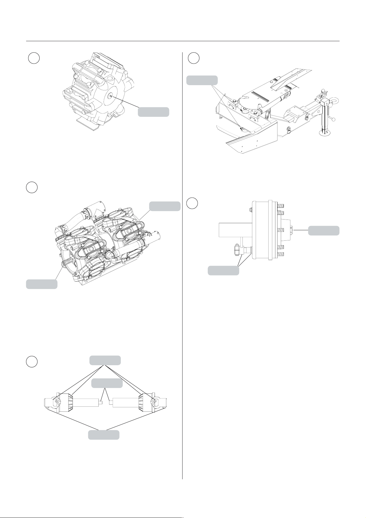
Maintenance
1
T201-0001
Double pump (HCFS only)
1
A - 50hA - 50h
A - 50h
A - 50hA - 50h
A - 50hA - 50h
A - 50h
A - 50hA - 50h
3
B - 10hB - 10h
B - 10h
B - 10hB - 10h
T222-0000x
4
All models
A - 200hA - 200h
A - 200h
A - 200hA - 200h
A - 50hA - 50h
A - 50h
A - 50hA - 50h
2
T226-0001
A - 10hA - 10h
A - 10h
A - 10hA - 10h
B - 50hB - 50h
B - 50h
B - 50hB - 50h
C - 50hC - 50h
C - 50h
C - 50hC - 50h
T202-0008
C - 50hC - 50h
C - 50h
C - 50hC - 50h
52
GB 13 03 03
Page 53

Without suspension
5
C - 250hC - 250h
C - 250h
C - 250hC - 250h
Maintenance
(Upside down)
B - 250hB - 250h
B - 250h
B - 250hB - 250h
(Upside down)
B - 250hB - 250h
B - 250h
B - 250hB - 250h
5
With suspension
C - 250hC - 250h
C - 250h
C - 250hC - 250h
C - 250hC - 250h
C - 250h
C - 250hC - 250h
B - 250hB - 250h
B - 250h
B - 250hB - 250h
B - 250hB - 250h
B - 250h
B - 250hB - 250h
B - 250hB - 250h
B - 250h
B - 250hB - 250h
T219-0007x
C - 250hC - 250h
C - 250h
C - 250hC - 250h
B - 250hB - 250h
B - 250h
B - 250hB - 250h
C - 250hC - 250h
C - 250h
C - 250hC - 250h
GB 13 03 03
B - 50hB - 50h
B - 50h
B - 50hB - 50h
B - 250hB - 250h
B - 250h
B - 250hB - 250h
T219-0008x
53
Page 54
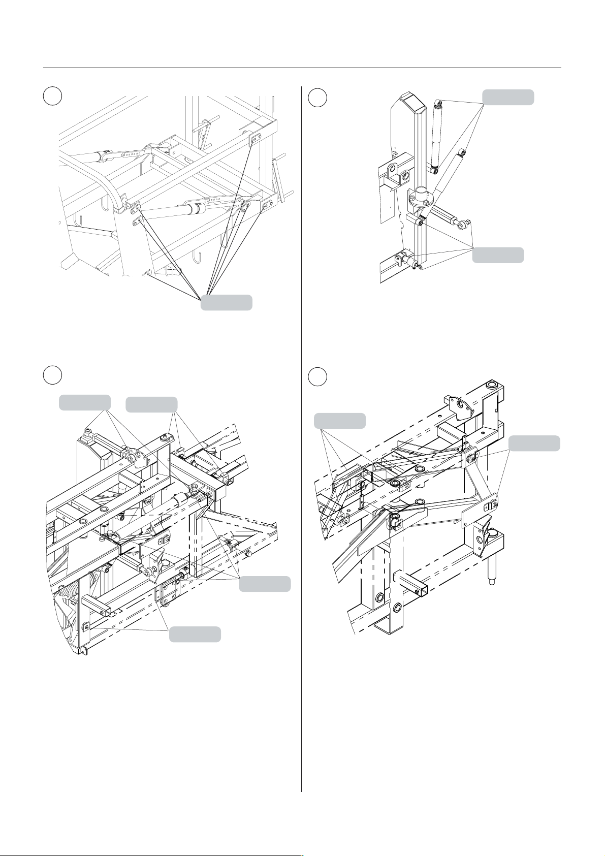
Maintenance
6
B - 50hB - 50h
B - 50h
B - 50hB - 50h
7
T202-0005
7
C - 50hC - 50h
C - 50h
C - 50hC - 50h
C - 50hC - 50h
C - 50h
C - 50hC - 50h
T210-0001
7
C - 50hC - 50h
C - 50h
C - 50hC - 50h
B - 50hB - 50h
B - 50h
B - 50hB - 50h
B - 50hB - 50h
B - 50h
B - 50hB - 50h
C - 50hC - 50h
C - 50h
C - 50hC - 50h
T210-0001
B - 50hB - 50h
B - 50h
B - 50hB - 50h
B - 50hB - 50h
B - 50h
B - 50hB - 50h
T210-0001
54
GB 13 03 03
Page 55
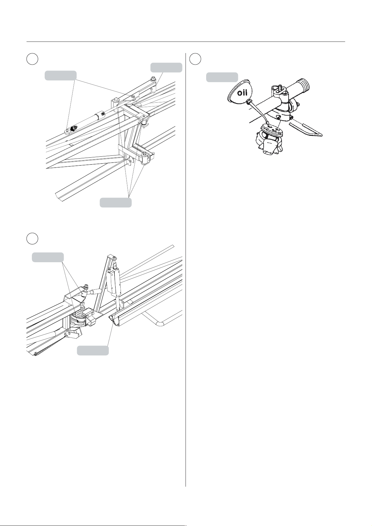
Maintenance
8
C - 50hC - 50h
C - 50h
C - 50hC - 50h
B - 50hB - 50h
B - 50h
B - 50hB - 50h
B - 50hB - 50h
B - 50h
B - 50hB - 50h
T210-0002
10
C - 500hC - 500h
C - 500h
C - 500hC - 500h
T219-0003
9
B - 50hB - 50h
B - 50h
B - 50hB - 50h
C - 50hC - 50h
C - 50h
C - 50hC - 50h
T210-0003
GB 13 03 03
55
Page 56

SerSer
vice and Maintenance intervice and Maintenance inter
Ser
vice and Maintenance inter
SerSer
vice and Maintenance intervice and Maintenance inter
Maintenance
vv
alsals
v
als
vv
alsals
10 hour10 hour
10 hour
10 hour10 hour
1. Suction filter, clean
2. Self-cleaning filter, check and clean
3. In-line filters, clean
4. Nozzle filters, clean
5. Spraying circuit, check for leaks
6. Brakes Air tank, drain
7. Brakes, check
8. Hydraulic oil level, check
9. Gear box oil level, check
10. Retighten bolts (suspension only)
50 hour50 hour
50 hour
50 hour50 hour
Do all previous mentioned +
1. Wheel bolts and nuts, tighten
2. Air brakes, check
3. Expansion bottle (SELF TRACK only), check air pressure
4. Transmission shaft, check
5. Tyre pressure, check
6. Gear box bolts, check
s sers ser
s ser
s sers ser
s sers ser
s ser
s sers ser
vicevice
vice
vicevice
vicevice
vice
vicevice
100 hour100 hour
100 hour
100 hour100 hour
Do all previous mentioned +
1. Fixed drawbar, check/adjust
250 hour250 hour
250 hour
250 hour250 hour
Do all previous mentioned +
1. Wheel bearings, check
2. Parking brake, inspect
3. Wheel brake, adjust
4. Air brake filters, clean
5. Hydraulic brakes, inspect
6. Hydraulic circuit, check
7. Expansion bottle (SELF TRACK only), check oil level
8. Hoses and tubes, check
9. Readjustment of the boom
500 hour500 hour
500 hour
500 hour500 hour
s sers ser
s ser
s sers ser
s sers ser
s ser
s sers ser
s sers ser
s ser
s sers ser
vicevice
vice
vicevice
vicevice
vice
vicevice
vicevice
vice
vicevice
Do all previous mentioned +
1. Hydraulic oil filter, change
56
GB 14 01 06
Page 57

Maintenance
1000 hour1000 hour
1000 hour
1000 hour1000 hour
Do all previous mentioned +
1. Wheel bearings and brakes, check
2. Transmission shaft, change parts
3. Hydraulic oil, change
4. Gear box oil, change
5. Hydraulic tank air filter, change
Occasional maintenanceOccasional maintenance
Occasional maintenance
Occasional maintenanceOccasional maintenance
Pump valves and diaphragms renewal
Cone check/renewal, EVC operating unit
Cone check/renewal, EVC distribution valve
Wear bush renewal, boom lift
Wear bush renewal, drawbar
Venting the hydraulic damping system (SELF TRACK)
TRACKER damper pressure setting (SELF TRACK)
Shock absorbers, inspect
Level indicator adjustment
Cord renewal, level indicator
Seal renewal, drain valve
Nozzle tubes and fittings
Adjustment of 3-way-valve
Change of bulbs
Adjustment of slanting control indicator cable
Transmission shaft, shield renewal
Constant velocity joint shielding
Change of tyres
Fan speed adjustment
Fan transmission priming
Fan transmission pressure adjustment
s sers ser
s ser
s sers ser
vice or yvice or y
vice or y
vice or yvice or y
earear
ear
earear
lyly
, whic, whic
ly
, whic
lyly
, whic, whic
hehe
vv
er comes fer comes f
he
v
er comes f
hehe
vv
er comes fer comes f
irir
ir
irir
stst
st
stst
Always check that all lock nuts are tight after adjustment
GB 14 01 06
57
Page 58
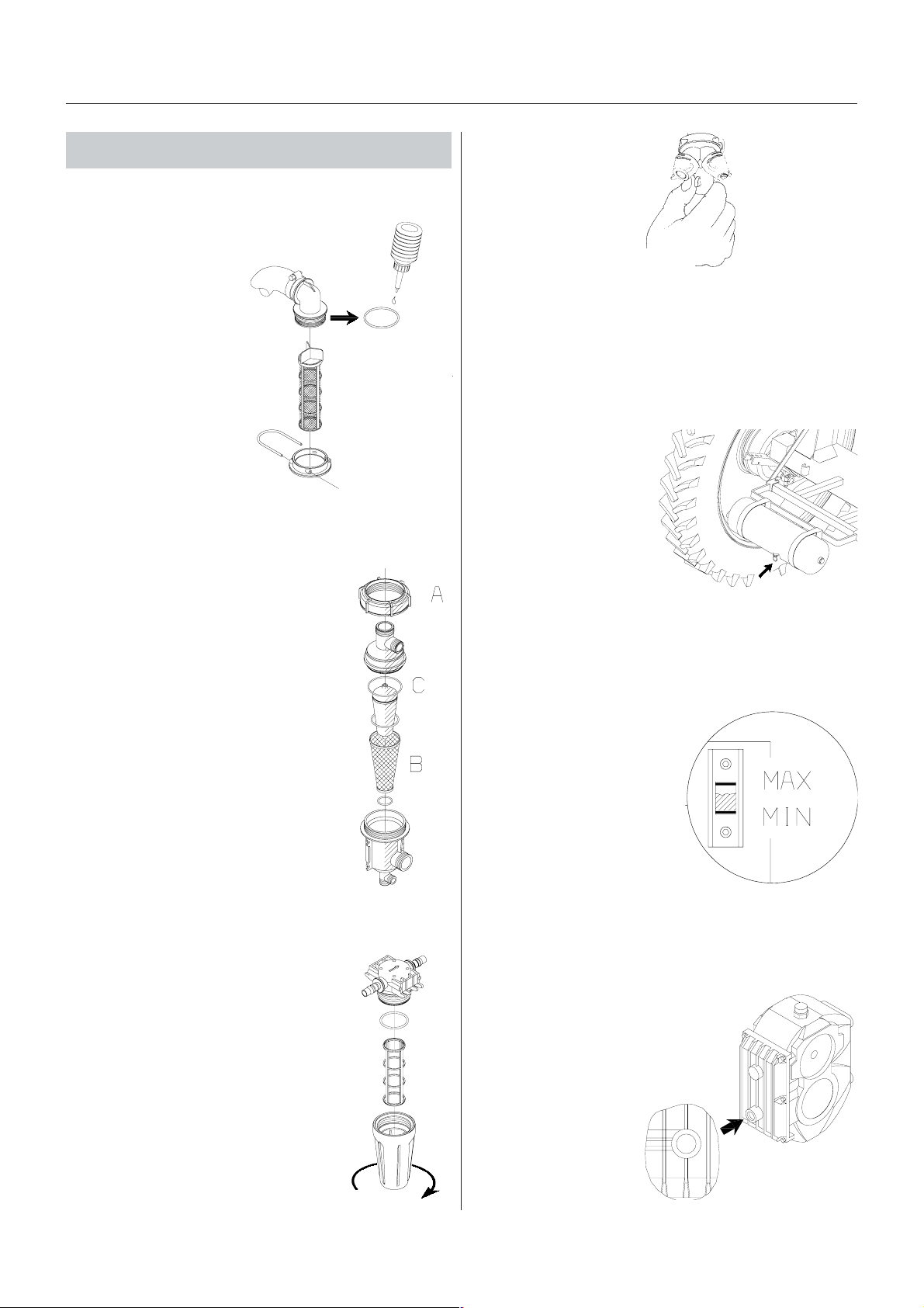
Maintenance
10 hour 10 hour
10 hour
10 hour 10 hour
1. Suction f1. Suction f
1. Suction f
1. Suction f1. Suction f
To service the suction
filter:
1. Pull the steel clip A out.
2. Lift the suction hose
fitting B from housing.
3. Filter guide and filter C
can now be removed.
To reassemble:
4. Press the guide onto
filter end.
5. Place the filter into
housing with guide
facing up.
6. Ensure the O-ring D on
the hose fitting is in
good condition and lubricated.
7. Refit the suction hose B and steel clip A.
s sers ser
s ser
s sers ser
ilterilter
ilter
ilterilter
vicevice
vice
vicevice
T180-0003
4. Nozzle f4. Nozzle f
4. Nozzle f
4. Nozzle f4. Nozzle f
Check and clean.
5. Spr5. Spr
5. Spr
5. Spr5. Spr
Fill with clean water, operate all functions and check for
leaks, use higher spray pressure than normal. Check
nozzle spray patterns visually using clean water.
6. Br6. Br
akak
6. Br
ak
6. Br6. Br
akak
Drain the air tank for
condensed water at the
drain valve.
ilterilter
ilter
ilterilter
aa
ying cirying cir
a
ying cir
aa
ying cirying cir
es Air tankes Air tank
es Air tank
es Air tankes Air tank
ss
s
ss
cuitcuit
cuit
cuitcuit
T180-0006
T191-0001
2. Self-Cleaning F2. Self-Cleaning F
2. Self-Cleaning F
2. Self-Cleaning F2. Self-Cleaning F
1. Unscrew nut A and open filter.
2. Check filter gauze B, clean if necessary
3. Lubricate O-ring C
4. Assemble filter again.
3. In-Line f3. In-Line f
3. In-Line f
3. In-Line f3. In-Line f
If the boom is equipped with In-Line
Filters unscrew the filter bowl to
inspect and clean the filter.
Alternative filters are available. See
section on Technical specifications Filters and nozzles.
ilter (ifilter (if
ilter (if
ilter (ifilter (if
ilterilter
ilter
ilterilter
f f
itted)itted)
f
itted)
f f
itted)itted)
T180-0004
7. Br7. Br
akak
7. Br
7. Br7. Br
Apply brake pedal and check function of trailer brakes.
8. Hy8. Hy
8. Hy
8. Hy8. Hy
Check that the oil level is
between min. and max. on
the sight glass. Clean the
area areound the filling cap
carefully and add fresh, clean
oil if the level is low. Regarding oil quality - see section the
section Lubricants.
9. Gear bo9. Gear bo
9. Gear bo
9. Gear bo9. Gear bo
Check the gear box oil level is reaching the sight glass.
Clean the area areound the filling
plug and add fresh, clean oil if
the level is low. Regarding oil
quality - see the section
Lubricants
eses
ak
es
akak
eses
drdr
aulic oil leaulic oil le
dr
aulic oil le
drdr
aulic oil leaulic oil le
x oil lex oil le
x oil le
x oil lex oil le
vv
elel
v
el
vv
elel
T219-0004
vv
elel
v
el
vv
elel
58
T180-0005
T219-0001
GB 14 02 02
Page 59
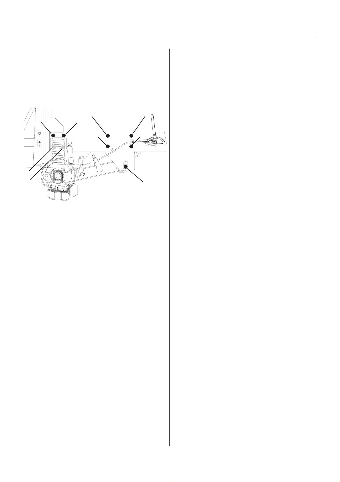
Maintenance
10. R10. R
etighten bolts (suspension only)etighten bolts (suspension only)
10. R
etighten bolts (suspension only)
10. R10. R
etighten bolts (suspension only)etighten bolts (suspension only)
Check that these 9 bolts - on each side of the COMMANDER - are tight. Retighten if necessary. Tightening
torque: Bolt 1 = 24 Nm (retain nut on the backside of the
mounting by a spanner while
adjusting bolt 1).
Bolt 2-9: 280 Nm
7
8
9
Bolt 8 and 9 are situated behind the spring.
4
6
5
3
2
T091-0004
1
GB 14 02 02
59
Page 60

50 hour 50 hour
50 hour
50 hour 50 hour
s sers ser
s ser
s sers ser
vicevice
vice
vicevice
Maintenance
5. T5. T
yryr
e pre pr
5. T
yr
5. T5. T
yryr
Check the tyre pressure according to the table below.
e pr
e pre pr
essuressur
essur
essuressur
ee
e
ee
1. Wheel bolts and n1. Wheel bolts and n
1. Wheel bolts and n
1. Wheel bolts and n1. Wheel bolts and n
Tighten wheel bolts and
nuts as follows with
following torque wrench
settings:
Wheel hub to rim plate:
490 Nm (362 lbft)
Rim plate to rim:
280 + 30 Nm
(207 + 22 lbft)
Tightening sequence:
See illustration.
2. Air br2. Air br
2. Air br
2. Air br2. Air br
The air brakes are checked for leaks by following
procedure:
1. Connect the snap-couplers to the tractor and fill the
trailer air tanks.
2. Check for leaks with brakes released.
3. Apply the brake up to full pressure.
4. Check for leaks with brakes applied.
akak
ak
akak
eses
es
eses
utsuts
uts
utsuts
T191-0002
eziseryT
59CR
44R59/032
)44x5.9(
84R59/032
)84x5.9(
44R59/072
)44x2.11(
84R59/072
)84x2.11(
64x4.21)25(6.3851/741
83x9.61 )32(6.1 251/141
83x4.81)32(6.1441/741
83x8.02 )81(2.1 151/451
IMPORTANT! If renewing tyres always use tyres with
min. load index as specified in the table.
WARNING! Never inflate tyres more than to the
pressure specified in the table. Over-inflated
tyres can explode and cause severe personal
injuries! See paragraph Tyre safety.
dednemmoceR
nierusserpnoitalfni
).i.s.p(rab
)25(6.3541/431
)25(6.3 741/631
)25(6.3151/041
)25(6.3 351/241
muminiM
xednIdaoL
2A/8A
002
3. Expansion bottle3. Expansion bottle
3. Expansion bottle
3. Expansion bottle3. Expansion bottle
(SELF TRA(SELF TRA
(SELF TRA
(SELF TRA(SELF TRA
Check air pressure in the
expansion tank for the hydraulic damping at the pressure gauge.
Fill through valve A
if necessary.
Air pressure: 5 bar (73 p.s.i.)
4. T4. T
rr
ansmission shaftansmission shaft
4. T
r
ansmission shaft
4. T4. T
rr
ansmission shaftansmission shaft
Check function and condition of the transmission shafts
protection guards. Replace possible damaged parts
CK only)CK only)
CK only)
CK only)CK only)
T191-0004
6. Gear bo6. Gear bo
6. Gear bo
6. Gear bo6. Gear bo
Check/retighten the gear box housing bolts to the
specified torque.
70 Nm (51 lbft).
x boltsx bolts
x bolts
x boltsx bolts
T109-0005
60
GB 14 03 02
Page 61
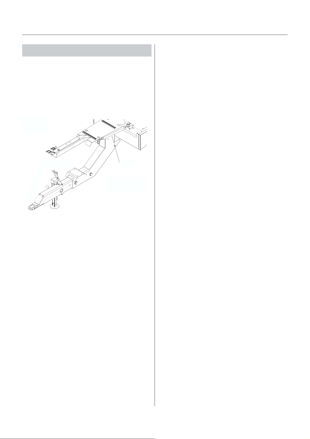
Maintenance
100 hour 100 hour
100 hour
100 hour 100 hour
1. Chec1. Chec
1. Chec
1. Chec1. Chec
only)only)
only)
only)only)
If to much play is found in the lateral movements of the
drawbar it must be adjusted.
Regulate on the turnbuckles A on each side in order to
adjust and centre the drawbar.
T251-0012x
s sers ser
s ser
s sers ser
k/adjust drk/adjust dr
k/adjust dr
k/adjust drk/adjust dr
vicevice
vice
vicevice
aa
wbar (Fwbar (F
a
wbar (F
aa
wbar (Fwbar (F
ixix
ed dred dr
ix
ed dr
ixix
ed dred dr
aa
a
aa
A
wbarwbar
wbar
wbarwbar
GB 14 04 01
61
Page 62
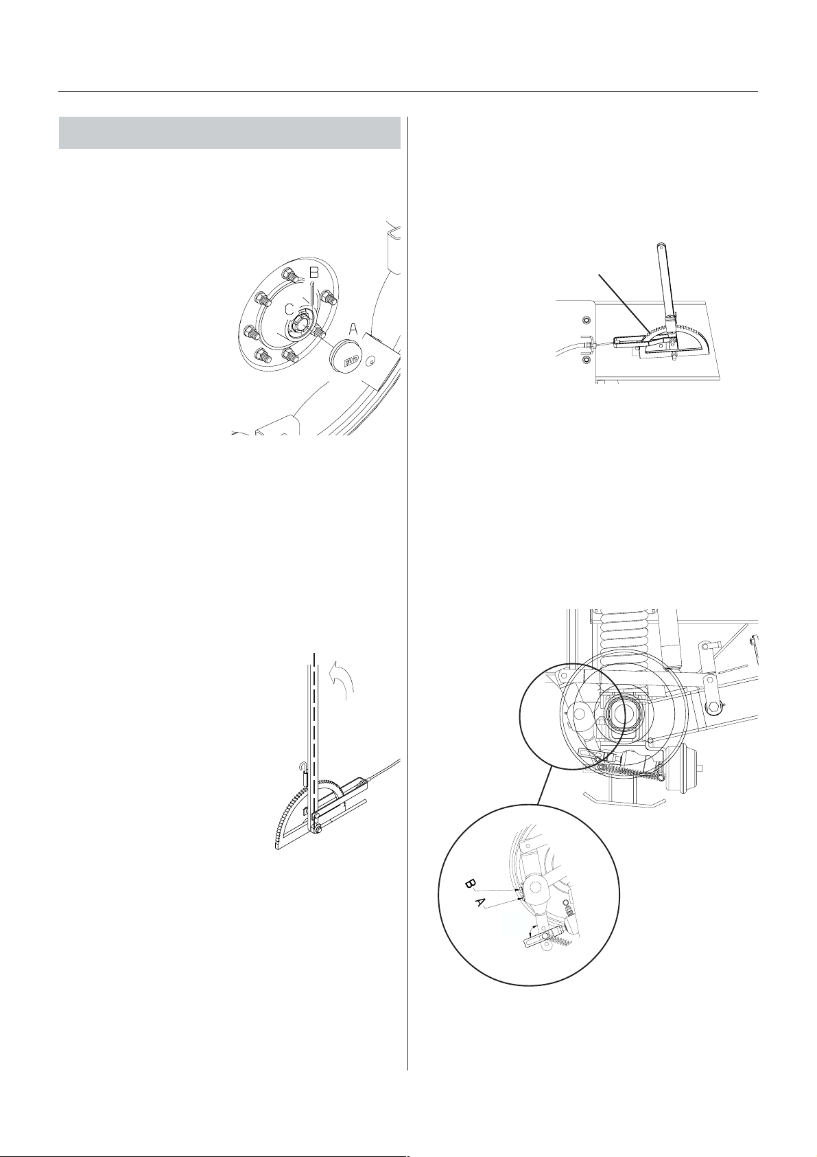
250 hour 250 hour
250 hour
250 hour 250 hour
1. Wheel bearings1. Wheel bearings
1. Wheel bearings
1. Wheel bearings1. Wheel bearings
Check for play in the wheel bearings:
s sers ser
s ser
s sers ser
vicevice
vice
vicevice
Maintenance
3. Br3. Br
akak
3. Br
3. Br3. Br
Lift the back of the COMMANDER from the ground. It is
recommended to use two lifting jacks, placed underneath the axle. Make sure the COMMANDER is stable
and secured before carrying out any adjustments.
e adjustmente adjustment
ak
e adjustment
akak
e adjustmente adjustment
1. Place stop wedges in
front of and behind LH
wheel and jack up RH
wheel
2. Rock the RH wheel to
discover possible play in
the bearings.
3. If any play, support the
wheel axle to prevent the
trailer from falling down
from the jack.
4. Remove hub cap A and
cotter pin B. Turn the
wheel and tighten the
castellated nut C until a slight resistance in the wheel
rotation is felt.
5. Loosen the castellated nut until the first notch horizontal or vertical - is aligned with the cotter pin
hole in the shaft.
6. Fit a new cotter pin and bend it.
7. Fill the hub cap with fresh grease and press it on to
the hub again.
8. Repeat the procedure on LH wheel.
1. Place the handbrake in the first jag. (Please refer to
illustration).
T191-0005
NOTE! The following adjustment must be carried out
simultaneously on both brakes. Therefore, alternately
adjust on both LH brake and RH brake.
2. Loosen nut B, lift and flip the small lock plate aside.
3. Adjust the nut A clockwise. Turn the nut 90° (1/4
turn) at a time - alternately on both LH and RH
brake.
After each 1/4 turn:
Check the hub by rotating it. Continue adjustment till
resistance occurs. This adjustment is completed, when
each hub is strained.
1st jag
T091-0004
2. Inspect par2. Inspect par
2. Inspect par
2. Inspect par2. Inspect par
Inspect the following:
The parking brake lever:
If it can be pulled further backwards
than 90° (midway), using a traction
of approximate 25 kg., the cable
needs to be adjusted.
kk
ing bring br
k
ing br
kk
ing bring br
akak
ak
akak
ee
e
ee
90
o
A
The parking brake cable:
When the parking brake is
relieved, the cable must be limp;
otherwise it needs to be adjusted.
Correct length: When the brake is relieved the cable
must be tight and yet not stretched.
Lengthening/shortening of the parking brake cable is
carried out by adjusting the nut A.
Inspect the parking brake cables for possible wear or
damages. Replace worn or damaged parts.
T021-0001
T091-0004
T101-0040
62
GB 14 05 02
Page 63

Maintenance
4. Air br4. Air br
4. Air br
4. Air br4. Air br
1. Clean the area around air filter(s) and
disconnect air hose from the tractor.
2. Hold one hand under the filter housing,
and pull out the retainer clip A. The filter
cartridge assembly will be pushed out by
the springs inside the filter housing.
3. Clean the filter cartridge. Use water and
an appropriate detergent or compressed
air.
4. Dry the parts and reinstall in the order
shown. The O-ring should be lightly
lubricated with silicone grease before
installation.
5. Hy5. Hy
5. Hy
5. Hy5. Hy
Apply brakes to full pressure and inspect brake lines for
damages or leaks. Replace damaged parts.
IMPORTANT! If the hydraulic brake lines have been
dismantled the circuit must be primed afterwards:
1. Loosen brake hose at both brake cylinders.
2. Apply brake until oil without air bubbles come out.
3. Tighten brake hose before relieving the brake again.
akak
ak
akak
drdr
aulic braulic br
dr
aulic br
drdr
aulic braulic br
e fe f
e f
e fe f
ilterilter
ilter
ilterilter
akak
ak
akak
s (ifs (if
s (if
s (ifs (if
eses
es
eses
f f
itted)itted)
f
itted)
f f
itted)itted)
A
9. R9. R
eadjustment ofeadjustment of
9. R
eadjustment of
9. R9. R
eadjustment ofeadjustment of
Please see next page.
T180-0007
the boom the boom
the boom
the boom the boom
6. Hy6. Hy
drdr
6. Hy
6. Hy6. Hy
Check the hydraulic circuit for leaks and repair if any.
7. Expansion bottle (SELF TRA7. Expansion bottle (SELF TRA
7. Expansion bottle (SELF TRA
7. Expansion bottle (SELF TRA7. Expansion bottle (SELF TRA
Check the oil level:
1. Depressurize the expansion
2. Remove the level plug B and
3. Tighten the plug again and
8. Hoses and tubes8. Hoses and tubes
8. Hoses and tubes
8. Hoses and tubes8. Hoses and tubes
Check all hoses and tubes for possible damages and
proper attachment. Renew damaged hoses or tubes.
aulic ciraulic cir
dr
aulic cir
drdr
aulic ciraulic cir
bottle through valve A first.
check that the oil level is
reaching the level hole. Add if
the level is low.
inflate the bottle to 5 bar air
pressure.
cuitcuit
cuit
cuitcuit
CK only)CK only)
CK only)
CK only)CK only)
T219-0005
GB 14 05 02
63
Page 64
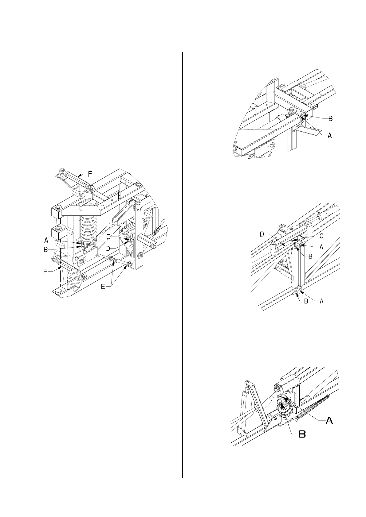
Maintenance
Boom rBoom r
Boom r
Boom rBoom r
1.Park the sprayer on a level surface
2.Unfold the boom completely
3.Lower tilt rams completely
4.Set the slanting control midway (piston rod length is 60
Following adjustments can now be carried out:
Suspension spring tension
1.Loosen the counter nuts A in either side and adjust the
2.Tighten the counter nuts again.
Pendulum return spring and cables
1.Ensure that the slanting ram is set midway
2.Loosen the counter nuts C and adjust the stop screws
3.Allowe max. 1 mm play between stop screw and arm.
4.Loosen the counter nuts E on the rigging screws, and
5.Tighten the counter nuts again.
Guide rods length adjustment
The guide rods length should normally not be necessary
to adjust. If the suspension has been dismantled, the
length must be checked or adjusted if necessary.
The trapeze and pendulum must hang freely. Adjust the
length of the rods F accordingly.
Loosen the counter nuts and adjust the rods.
eadjustmenteadjustment
eadjustment
eadjustmenteadjustment
mm)
tension of the vertical springs on the bolts B to suit
the boom weight. The adjustment is correct when the
guide rods are approximately level.
D until the V-shaped mechanism is in symmetry.
adjust the length of the rigging screws until the boom
is level. The correct adjustment is reached when the
spring opens 1 mm between the threads
Inner section folding adjustment
The boom tip must point slightly forward. If
necessary adjust the inner
section folding as follows:
1.Depressurize the
folding rams
2.Loosen counter
nut A
3.Adjust stop
screw B until
the correct
setting is
reached.
4.Tighten
counter nuts
again
Outer section folding adjustment
The outer sections must be aligned with the inner
sections. If necessary adjust the outer sections as
follows:
1.Depressurize the folding rams
2.Loosen counter nuts A
and C.
3.Loosen the screws B.
4. Pressurize the
folding ram until it is
fully extended.
5.Adjust on the rigging
screw D until the
correct setting is
reached.
6.Adjust the stop
T100-0001
screws B up against
the inner section.
7.Tighten counter nuts
again
Breakaway section adjustment
The breakaway section must release when a force of
approximately 150 N (34 lb) is applied to the extremity of
the breakaway section. If
necessary the release
force is adjusted as
follows:
1.Make sure the
claw coupling is
correctly
lubricated.
2.Loosen the
counter nut A
3.Adjust the nut
B until the
breakaway will release at a force of 150 N (34 lb)
applied at the extremety of the section.
4.Tighten the counter nut again.
T100-0004
T100-0002
64
GB 14 00 01
Page 65

Maintenance
500 hour500 hour
500 hour
500 hour500 hour
1. Hy1. Hy
drdr
1. Hy
dr
1. Hy1. Hy
drdr
Change the hydraulic oil filter after the first 50 hours and
then every 500 hours or once a year - whichever comes
first.
Always change the oil filter if the vacummeter indicator is
in the red area. Check when the oil has reached working
temperature.
s sers ser
s ser
s sers ser
aulic oil faulic oil f
aulic oil f
aulic oil faulic oil f
vicevice
vice
vicevice
ilterilter
ilter
ilterilter
T192-0003
1. Place e.g. a drain pan or a cloth under the filter to
retain waste oil and unscrew the filter cartridge.
2. The new filter cartridge is filled with fresh clean
hydraulic oil. Apply a thin oil film to the cartridge seal.
3. Screw the filter cartridge on until the seal is lying
against the flange.
4. Tighten the filter cartridge another 1/2 to 3/4 turn.
5. Check hydraulic oil level - top up with fresh clean
hydraulic oil if necessary.
6. Set the blower in neutral, start the tractor P.T.O. and
let it run idle for 5 min. to prime the sysstem.
7. After 5 min. the blower r.p.m. can gradually be increased to full speed.
Disposal of used hydraulic filter cartridges must only
take place in accordance with local legislation.
GB 14 06 01
65
Page 66
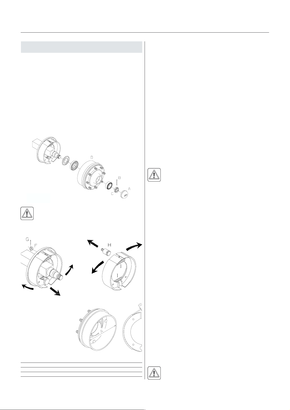
Maintenance
1000 hour 1000 hour
1000 hour
1000 hour 1000 hour
1. Wheel bearings and br1. Wheel bearings and br
1. Wheel bearings and br
1. Wheel bearings and br1. Wheel bearings and br
Check the condition of the bearings and brake wear
parts in the following way:
1. Place stop wedges in front of and behind LH wheel
and jack up RH wheel.
2. Support the trailer with axle stands.
3. Remove the wheel.
4. Remove the hub cap A, cotter pin B and castle nut C.
5. Pull off the wheel hub and brake drum assembly. Use
a wheel puller if necessary.
6. Vacuum clean the brake drum D for brake dust or
rinse with water.
s sers ser
s ser
s sers ser
vicevice
vice
vicevice
akak
ak
akak
eses
es
eses
T191-0006
IMPORTANT! The specified min. thickness is the
absolute minimum which must never be exceeded.
Renew the parts if they would reach the above dimensions before next service inspection.
IMPORTANT! Renewal of brake linings or brake drums
must be done both sides at the same time.
NOTE! If the brake drum must be removed from the
hub, a hydraulic press is required to press the wheel
studs out.
10.Remove the clevis pin between the air diaphragm
cylinder and brake cam lever.
11.Remove the cotterpin G and nut F , the brake shoe
anchor bolt H and slide the brake shoes over the
cam. Twist the pair of brake shoes to remove the
shoe return springs I. Replace brake shoes if the
linings are worn.
12.Apply a small qty. of copper paste on moving parts
and assemble the brake shoes and shoe return
springs again.
WARNING! Do not get oil, grease or copper paste
in contact with the brake linings and drums.
WARNING! Brake dust can cause severe health
injuries! Avoid inhalation of brake dust! Use
respirator when servicing the brakes. Do not clean
brakes with compressed air! Use vacuum cleaner or
rinse with water to avoid brake dust being blown around.
T191-0007
T191-0008
7. Rinse the remaining parts on the brake carrier plate
with water and dry them.
8. Remove roller bearings
E, clean all parts in
degreasing detergent
and dry them.
9. Check the brake drum
diameter and lining
thickness - renew if worn.
Max. wear rates on brake components, mm (in)
Model 2200/2800 3200/4200
Max. drum diameter A 302 (11.8897) 402 (15.8388)
Min. lining thickness B 2.0 (0.07874) 4.0 (0.15748)
T191-0009
T191-0010
13.Fit the shoe assembly with the anchor bolt first. Then
pull the shoes away from each other and slide them
over the cam afterwards. Tighten the anchor bolt
castellated nut again and fit a new cotter pin.
14.Check roller bearings for discoloration and wear renew if worn or damaged.
15.Assemble the hub and bearings using a new sealing
ring J.
16.Fill the hub and bearings with fresh grease before
fitting it to the shaft.
17.Fit the castellated nut. Rotate the hub and tighten the
castellated nut until a slight rotation resistance is felt.
18.Loosen the castellated nut again until the first notch
is aligned with the cotter pin hole in the shaft.
NOTE! The shaft has a vertical and an horizontal cotter
pin hole. Use the one first aligned with the notch when
loosening the castellated nut.
19.Fit a new cotter pin and bend it.
20.Fill the hub cap with fresh grease and carefully press
it on to the hub.
21.Adjust the brakes as described in 200 hours service.
22.Fit the wheel again and tighten the wheel nuts. See
section 50 hours service regarding torque wrench
setting.
Tighten all bolts to half the specified torque first, then
to the full specified torque.
23.Tighten again after 10 hours of work. Check the
torque every day until it is stabilised.
WARNING! If you do not feel totally confident
changing wheel bearings or brake shoes contact
your HARDI dealers workshop.
66
GB 14 07 01
Page 67
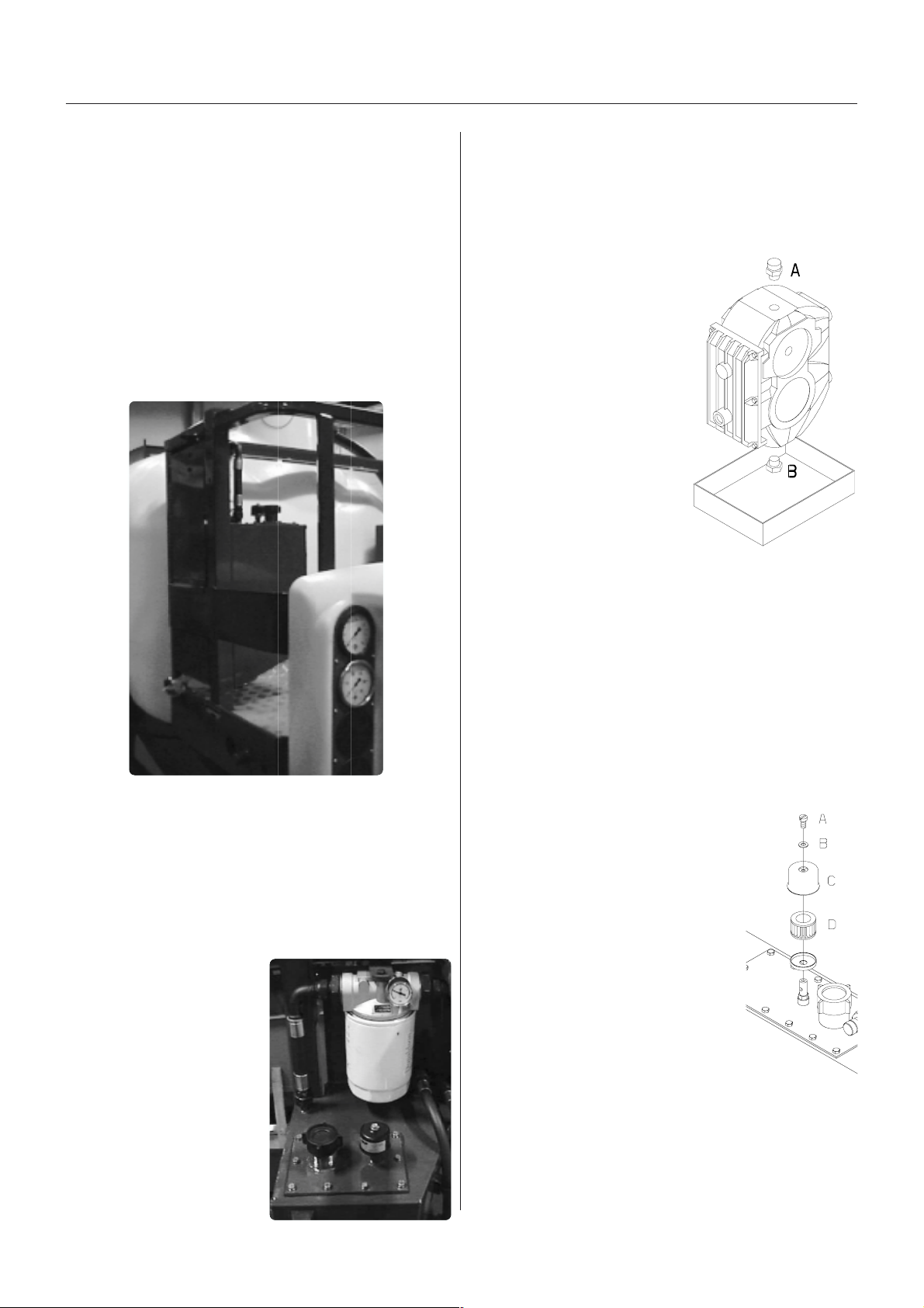
Maintenance
2. T2. T
rr
ansmission shaftansmission shaft
2. T
r
ansmission shaft
2. T2. T
rr
ansmission shaftansmission shaft
Change the protection tube nylon bearings as described
under Replacement of transmission shaft protection
tubes in the part Occasional Maintenance.
3. Hy3. Hy
drdr
3. Hy
3. Hy3. Hy
The hydraulic oil is changed every 1000 hours or once a
year - whichever comes first. The hydraulic oil change is
best done when the fan has been working for at least
one hour and the oil has reached working temperature.
Firstly, the used oil must be drained from the tank; this is
done by the tap A.
aulic oil caulic oil c
dr
aulic oil c
drdr
aulic oil caulic oil c
hanghang
ee
hang
e
hanghang
ee
A
Note local legislation regarding disposal of waste oil.
4. Gear bo4. Gear bo
4. Gear bo
4. Gear bo4. Gear bo
The first gear box oil change must be done after 50
hours, then every 1000 hours or once a year - whichever
comes first. The gear box oil
change is best done when the
machine has been working for
at least one hour and the oil
has reached working temperature.
1. Clean the area around
filling plug/breather A, dip
stick B and drain plug C
thoroughly.
2. Place a tray under the
drain plug to retain the
waste oil.
3. Unscrew the filling and
drain plugs and drain the
gear box oil.
4. Refit the drain plug using a
new seal - retighten.
5. Fill with fresh, clean oil until the level reaches the
sight glass.
Approx. oil quantity: 1.0 l (35.2 fl.oz.)
Regarding oil quality, see section on Lubricants
6. Refit the dip stick and filling plug - retighten.
x oil cx oil c
x oil c
x oil cx oil c
hanghang
hang
hanghang
ee
e
ee
T219-0002
T067-0008
1. Remove the cap from the tap A and fit a hose connection + tube (½) to the tap A.
2. Open the ball-valve on the tap and lead the waste oil,
via the tube, into an appropriate container.
3. Close the ball-valve and fit and tighten the cap to the
tap A again when all the waste oil has been drained.
Additionally, new oil is filled into the tank.
1. Clean the area around
the oil filling cap B.
2. Unscrew the filling cap
and fill the tank with
fresh, clean hydraulic oil
until the level is between
min. and max. on the
level glass. The tank
contains approx.
45 l. Regarding oil
specification - see
section on Lubricants
3. Fit the filling cap again.
B
T067-0009
Disposal of waste oil must only be carried out in accordance with local legislation.
5. Hy5. Hy
drdr
5. Hy
5. Hy5. Hy
Change the hydraulic tank breathing filter.
1. Clean the area around the air filter
2. Remove screw A, washer B and
3. Renew the filter cartridge D.
4. Reassemble in reverse order.
aulic tank air faulic tank air f
dr
aulic tank air f
drdr
aulic tank air faulic tank air f
thoroughly.
cap C.
ilterilter
ilter
ilterilter
T191-0011
GB 14 07 01
67
Page 68
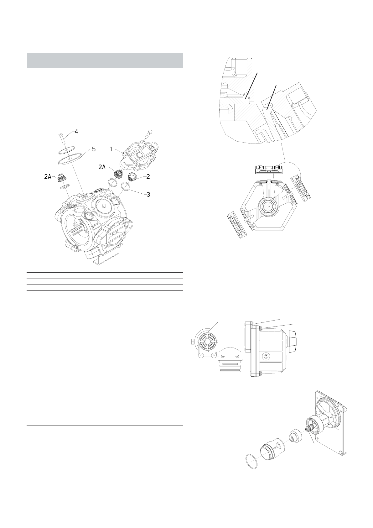
Maintenance
Occasional maintenance Occasional maintenance
Occasional maintenance
Occasional maintenance Occasional maintenance
The maintenance and renewal intervals for the following
will depend very much on the conditions under which the
sprayer will be operated and are therefore impossible to
specify.
correct
wrong
Pump vPump v
Pump v
Pump vPump v
Diaphragm pump overhaul kit (valves, seals, diaphragms etc.)
alvalv
es and diaes and dia
alv
es and dia
alvalv
es and diaes and dia
Pump model HARDI part No.
363 750342
463 750343
phrphr
phr
phrphr
aa
gms rgms r
a
gms r
aa
gms rgms r
eneene
ene
eneene
ww
w
ww
alal
al
alal
B
T261-0001
T192-0005x
Cone cCone c
Cone c
Cone cCone c
If it becomes difficult to build up sufficient pressure or if
pressure fluctuations occur, it may be necessary to
renew cone and cylinder. A HARDI kit is available for this
purpose. Ref. no. 741293.
hechec
hec
hechec
k/rk/r
k/r
k/rk/r
eneene
ene
eneene
ww
al EVal EV
w
al EV
ww
al EVal EV
C operC oper
C oper
C operC oper
aa
ting unitting unit
a
ting unit
aa
ting unitting unit
Valves
Remove valve cover 1 before changing the valves 2 -
note their orientation so they are replaced correctly!
NOTE: One special valve with white flap 2A is used. It
has to be placed in the valve opening shown.
It is recommended to use new gaskets 3 when changing
or checking the valves.
Diaphragms
Remove the diaphragm cover 4. The diaphragm 5 may
then be changed. If fluids have reached the crankcase,
re-grease the pump thoroughly. Also check that the drain
hole at the bottom of the pump is not blocked. Reassemble with the following torque setting.
Pump model Diaphragm cover Nm Diaphragm bolt Nm
463 90 90
463 90 90
1 Nm = 0.74 lbft
IMPORTANT! Before tightening the 4 bolts for the
diaphragm cover B the diaphragm must be positioned
between centre and top to ensure correct sealing between diaphragm pumphousing and diaphragm cover.
Turn crank shaft if necessary.
1. Remove 4 x screws A and remove the housing.
2. Remove 4 x screws B.
B
A
3. Replace cylinder C and O-ring D.
4. Loosen the nut E, remove and replace
the cone F.
5. Reassemble in reverse order.
F
C
D
E
T192-0037x
68
GB 14 08 01
Page 69
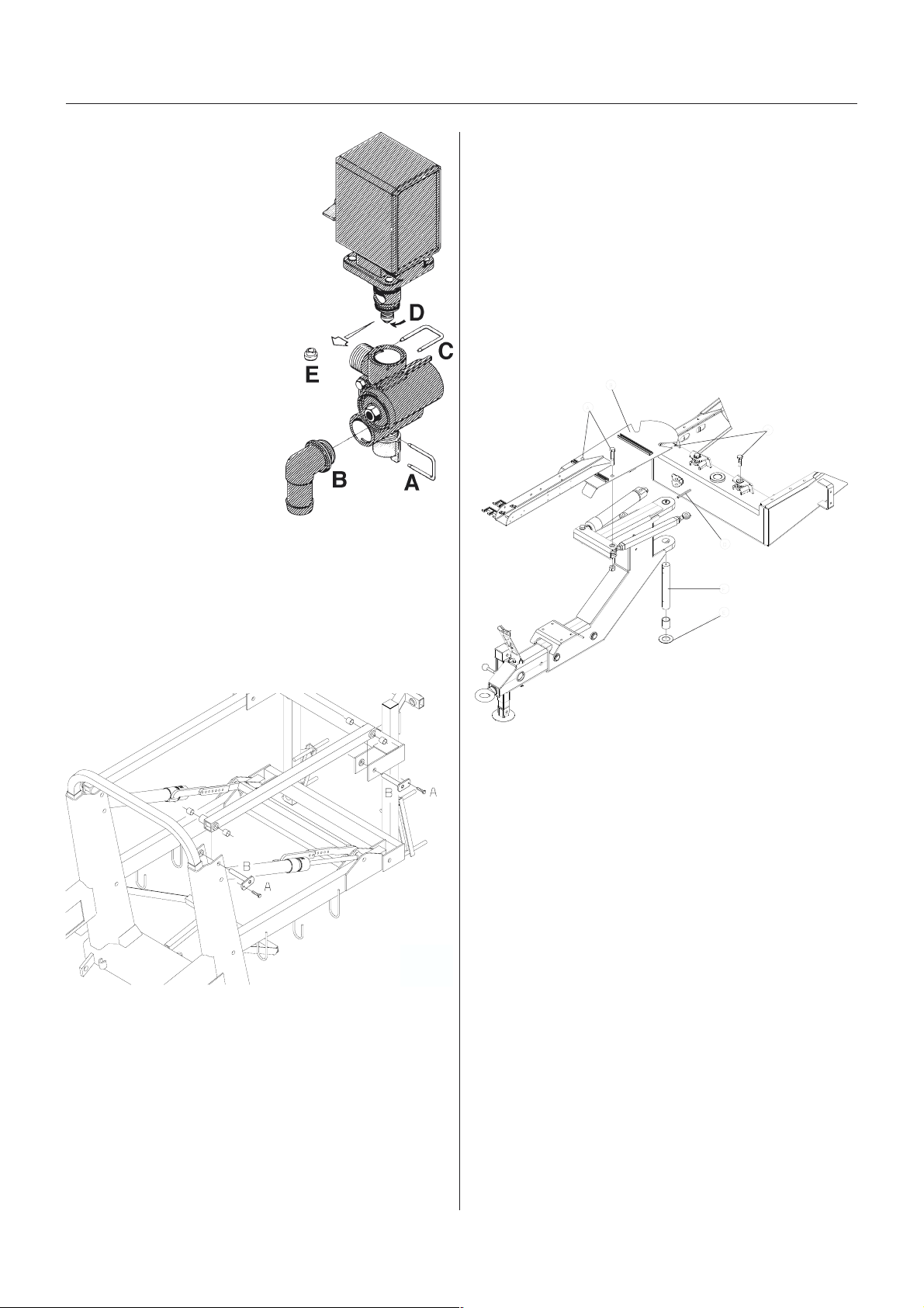
Maintenance
Cone cCone c
Cone c
Cone cCone c
EVEV
EV
EVEV
Periodically check the distribution valves for proper sealing.
Do this by running the sprayer
with clean water and open all
distribution valves.
Cautiously remove the clip A
and pull out the hose B for the
pressure equalisation device.
When the housing is drained,
there should be no liquid flow
through the pressure equalisation device. If there is any
leakage, the valve cone E must
be changed.
Remove the clip C and lift the
motor housing off the valve
housing. Then unscrew the
screw D and replace the valve cone E. Reassemble in
reverse order.
hechec
hec
hechec
C distribC distrib
C distrib
C distribC distrib
k/rk/r
eneene
k/r
ene
k/rk/r
eneene
ution vution v
ution v
ution vution v
ww
w
ww
al,al,
al,
al,al,
alvalv
alv
alvalv
ee
e
ee
6. The lower arms must be disconnected simultaneously.
Grease all grease nipples.
7. Remove the lifting gear again.
WW
ear bear b
ush rush r
eneene
ww
al, dral, dr
aa
W
ear b
ush r
ene
w
WW
ear bear b
ush rush r
eneene
(all TRA(all TRA
(all TRA
(all TRA(all TRA
If too much play is found in the drawbar the wear
bushes must be renewed.
CKER models)CKER models)
CKER models)
CKER models)CKER models)
A
ww
B
al, dr
al, dral, dr
wbarwbar
a
wbar
aa
wbarwbar
C
D
WW
ear bear b
ush rush r
eneene
ww
W
ear b
ush r
WW
ear bear b
The wear bushes are inspected and renewed before
they are worn through.
1. Connect the trailer to a tractor and unfold the booms
to working position.
2. Lift the boom centre frame with a lifting device and
support it until the load is taken off the parallelogram
arms.
3. Remove the screws A, and pull out the pins B at one
of the upper parallelogram arms and renew the wear
bushes.
4. Refit the arm.
5. Repeat this on the other upper arm.
ush rush r
ene
eneene
al, boom liftal, boom lift
w
al, boom lift
ww
al, boom liftal, boom lift
T191-0012
F
E
T251-0017
1. Place stop wedges in front of and behind both
wheels.
2. Jack up the frame and support it properly.
3. If not a SELF TRACK model: Remove the drawbar
extension to reduce the weight of the drawbar.
4. Loosen the two bolts A and support the bracket B in
order to keep it in a level position (e.g. by a rope
fastened to the platform railing).
5. Without dismantling the hydraulic system the hydraulic rams are removed from the drawbar by loosening
the nuts C.
6. Support the drawbar and remove the two pin bolts D,
the washer E and the pin F.
7. Move the drawbar to the side and support it.
8. Press out the worn bushes and fit new ones.
9. Assemble again in reverse order.
10. Grease through grease nipples and remove jack
and wedges.
11. Fit the extension piece in the drawbar again and
place the sprayer on the support leg
GB 14 08 01
69
Page 70
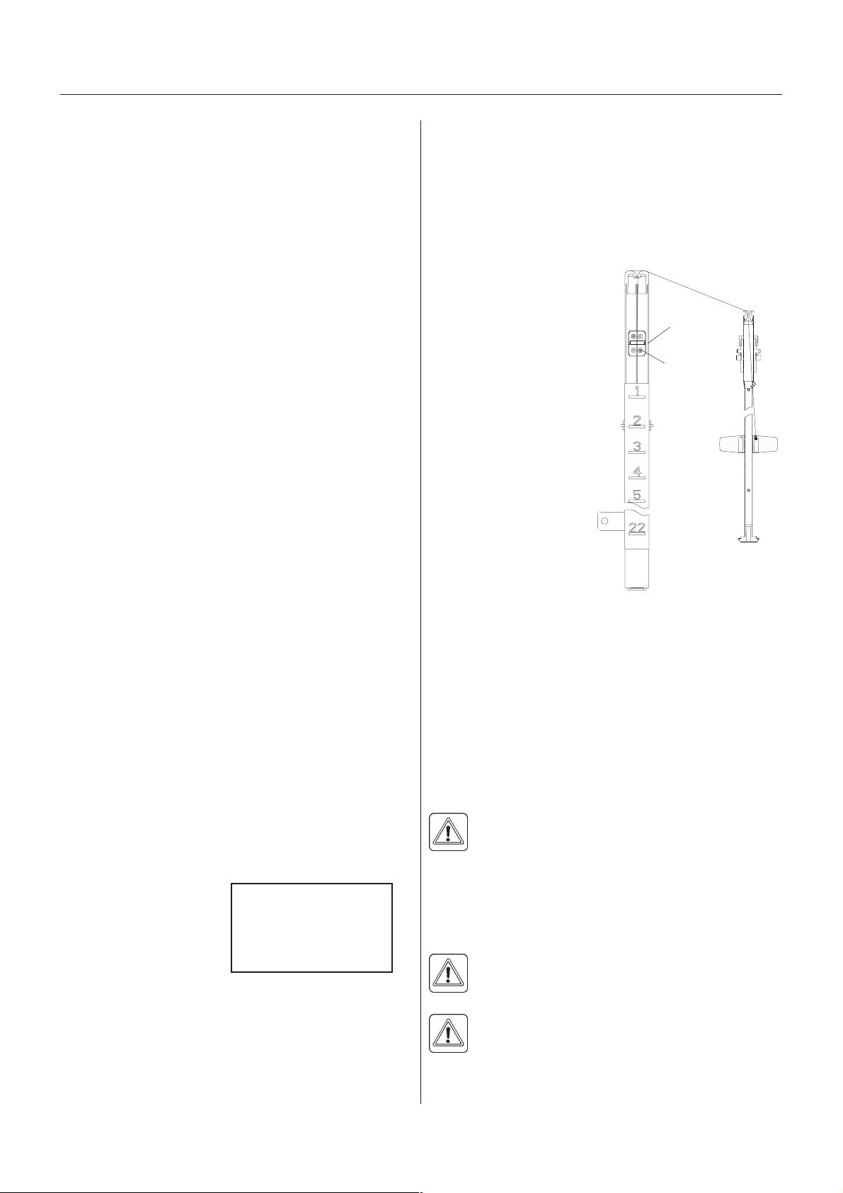
Maintenance
VV
enting the hyenting the hy
V
enting the hy
VV
enting the hyenting the hy
(SELF TRA(SELF TRA
(SELF TRA
(SELF TRA(SELF TRA
The following venting procedure requires a special
venting kit, HARDI ref. no. 720725.
1. Place the trailer on the support leg so that the yoke
goes free from the tractor and the rams can work
freely.
2. Relieve the pressure in the expansion tank and
remove the hydraulic hose.
NOTE! Plug the hose. If this is neglected, the pressure
gauge may be damaged.
3. Fit the two test hoses in the pressure gauge outlets on
the rams (at the rear of the track system).
4. Move the track system from one side to the other
approx. 10 times (full swing).
5. Loosen the plug very carefully in order to leak the air
out of the system.
6. Fit the hydraulic hose on the expansion tank.
7. Remove the level plug and using the tractor hydraulics, cautiously fill oil in the expansion tank until it
reaches the level plug.
8. Fit the level plug and fill the expansion tank to an air
pressure of 5 bar.
9. Fit the 0-400 bar pressure gauge on the pressure
gauge outlet at the ram. Adjust the excess-pressure
valve to approx. 40 bar.
drdr
aulic damping syaulic damping sy
dr
aulic damping sy
drdr
aulic damping syaulic damping sy
CK only)CK only)
CK only)
CK only)CK only)
stemstem
stem
stemstem
ShocShoc
k ak a
Shoc
ShocShoc
If the shock absorbers loose their efficiency or start
leaking oil, they should be replaced.
LeLe
vv
Le
v
LeLe
vv
The level indicator reading should be checked regularly.
When the tank is empty,
the float should lie on the
stop pin, of the rod, and
the O-ring on the indicator
should be positioned at
the top position line A.
If any deviation is found,
pull out the plug B, loosen
screws C, and adjust the
length of the cord.
bsorberbsorber
k a
bsorber
k ak a
bsorberbsorber
el indicael indica
el indica
el indicael indica
ss
s
ss
tor adjustmenttor adjustment
tor adjustment
tor adjustmenttor adjustment
B
A
C
T191-0018
On flat ground it is possible to work with a lower opening
pressure. This gives a more sensible reaction but it also
results in the fact that the trailer can swing when driving
on hilly ground and when swinging at high speed.
TRATRA
CKER damping prCKER damping pr
TRA
CKER damping pr
TRATRA
CKER damping prCKER damping pr
TRATRA
CK only)CK only)
TRA
CK only)
TRATRA
CK only)CK only)
The hydraulic pressure relief valves in the TRACKERs
damping system is factory set to open at appro.. 40 bar
(580 p.s.i.) which is adequate for most conditions.
If the damping seems too soft or too hard, the settings can be adjusted on the screws shown.
essuressur
essur
essuressur
illustration
e setting (SELFe setting (SELF
e setting (SELF
e setting (SELFe setting (SELF
CorCor
d rd r
eneene
ww
al, leal, le
vv
Cor
d r
ene
w
CorCor
d rd r
eneene
If the cord on the level indicator has to be changed, the
float guide pole is removed:
1. Remove the tank drain valve (see paragraph Main
tank drain valve) and loosen the fitting holding the
pole in position.
2. Pull the pole down through the drain valve hole till it is
free in the top of the tank.
3. The pole can now be taken out of the tank through
the filling hole.
DANGER! Do not attempt to enter the tank - the
float pole can be removed from outside the tank!
Seal rSeal r
Seal r
Seal rSeal r
If the main tank drain valve leaks, the seal and seat can
be changed the following way.
eneene
ene
eneene
DANGER! Do not enter the inside of the tank the parts can be changed from underneath the
tank!
WARNING! Use eye / face protection mask when
dismantling the tank drain valve!
ww
ww
al, dral, dr
w
al, dr
ww
al, dral, dr
al, le
al, leal, le
el indicael indica
v
el indica
vv
el indicael indica
ain vain v
ain v
ain vain v
alvalv
alv
alvalv
tortor
tor
tortor
ee
e
ee
70
1. Make sure the tank is empty and clean.
2. The valve must be closed and the string loose.
GB 14 08 01
Page 71
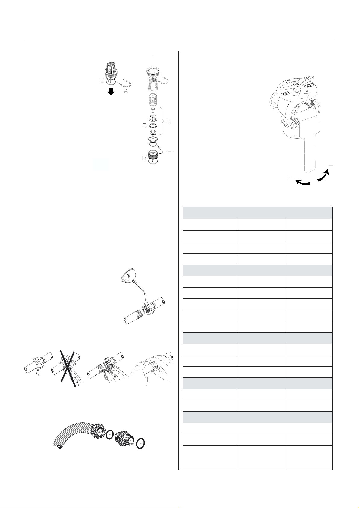
Maintenance
3. Pull out the clip A and
pull down connecting
piece B. The entire
valve assembly can
now be pulled out.
4. Check cord and valve
flap assembly C for
wear, replace seal D
and assemble again.
5. Assemble the valve
assembly again using
a new valve seat E.
Lubricate O-rings F
before assembly.
6. Fit clip A again.
NOTE! Check function of
valve with clean water
before filling chemicals into the tank.
Nozzle tubes and fNozzle tubes and f
Nozzle tubes and f
Nozzle tubes and fNozzle tubes and f
Poor seals are usually caused by:
ittingsittings
ittings
ittingsittings
T191-0016
Adjustment ofAdjustment of
Adjustment of
Adjustment ofAdjustment of
The MANIFOLD valve can be adjusted if it is too tight to
operate - or if it is too loose (= liquid leakage).
Use a suitable tool and adjust
the toothed ring inside the
valve as shown on the drawing.
ChangChang
Chang
ChangChang
Overview of bulbs used.
e ofe of
e of
e ofe of
noitcnuF)NID(epytbluBttaW/tloV
b b
b
b b
3-w 3-w
3-w
3-w 3-w
ulbsulbs
ulbs
ulbsulbs
aa
a
aa
y-vy-v
y-v
y-vy-v
ALLEH,pmalibmocraeR
alvalv
alv
alvalv
ee
e
ee
T090-0006
- missing O-rings or gaskets
- damaged or incorrectly seated O-rings
- dry or deformed O-rings or gaskets
- foreign bodies
In case of leaks:
T199-0001
DO NOT overtighten. Disassemble, check condition and
position of O-ring or gasket.
Clean, lubricate and reassemble.
The O-ring must be lubricated
ALL THE WAY ROUND before
fitting on to the nozzle tube. Use non-mineral lubricant.
T199-0001
For RADIAL connections only hand-tighten them.
pmalraeRW5RW5/V21
pmalpotSW12PW12/V21
rotacidninoitceriDW12PW12/V21
)sdraobgninrawhtiw(AKEG,pmalibmocraeR
noitcnuF)NID(epytbluBttaW/tloV
pmalraeRW5RW5/V21
pmalpotSW12PW12/V21
rotacidninoitceriDW12PW12/V21
tnorf,pmalnoitisoP)AKEG(W5/V21
spmalkrowdnamooB
noitcnuF)NID(epytbluBttaW/tloV
pmalmooB3HW55/V21
pmalgnikroW89421W12/V21
ALLEH,pmaletalprebmuN
noitcnuF)NID(epytbluBttaW/tloV
pmaletalprebmuNW01RW01/V21
For AXIAL connections, a little mechanical leverage may
be used.
T199-0002
GB 14 08 01
pmalibmocgnikramediS
noitcnuF)NID(epytbluBttaW/tloV
ibmocgnikramediS
pmal
wolleyder,etihw
W5RW5/V21
.blubehtevomerotgnisuohrebburehtmorfylluferacsnelehttuoesirP
039
71
Page 72
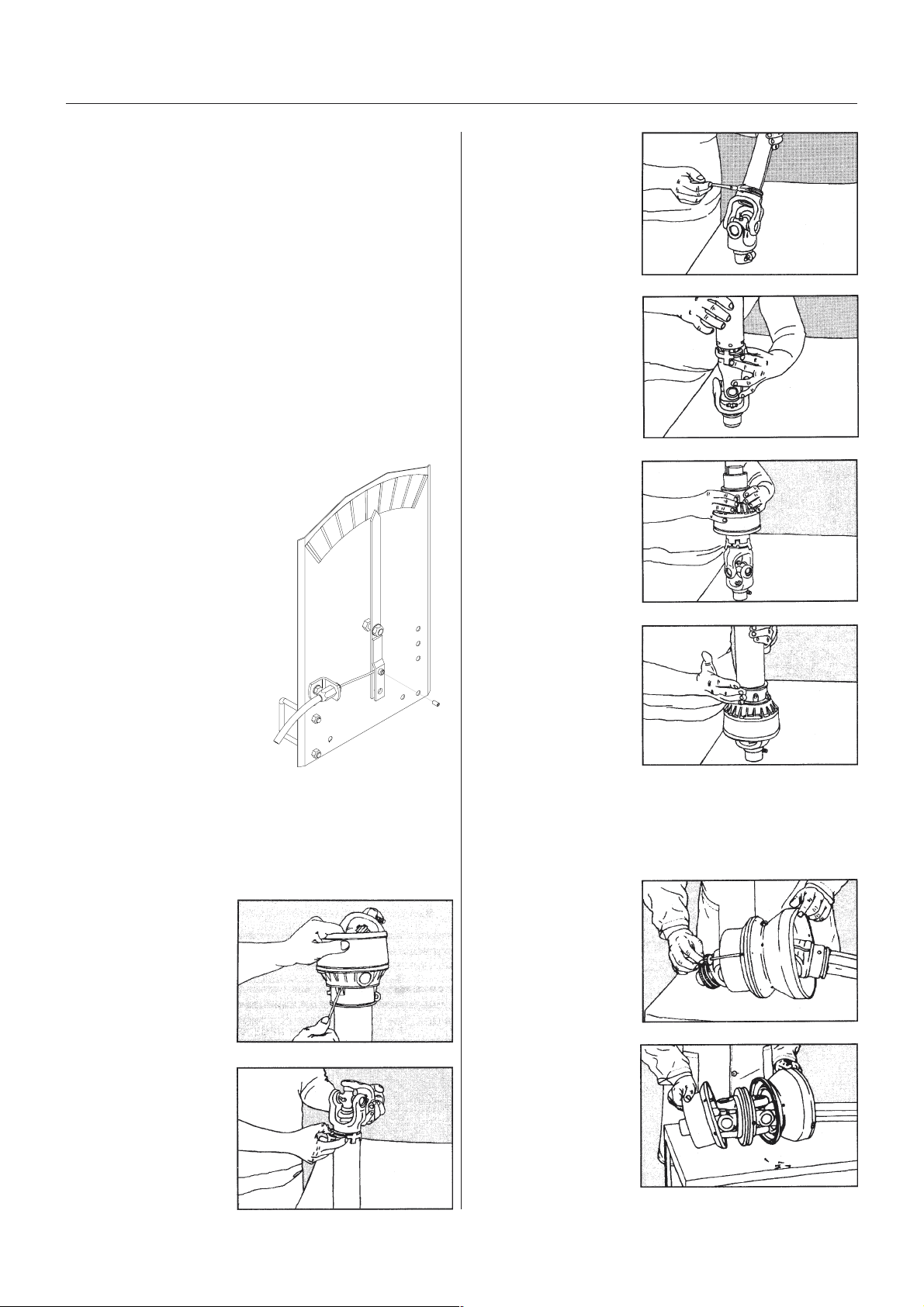
Maintenance
To change a bulb
1. Switch off the light
2. Loosen the screws on the lamp and remove the cover
or lens.
3. Remove the bulb
4. Fit a new bulb, refit the cover and tighten the screws.
NOTE! If halogen bulbs are used, never touch the bulb
with the fingers. Natural moisture in the skin will cause
the bulb to burn out when the light is switched on.
Always use a clean cloth or tissue when handling
halogen bulbs.
Adjustment ofAdjustment of
Adjustment of
Adjustment ofAdjustment of
If the position of the pointer on the indicator does not
correspond to the actual boom position, the pointer A
can be adjusted.
1. Loosen the small bolt B
sufficiently to allow the wire
C to be adjusted.
2. Place the pointer A in
correct position and fasten
bolt B against the wire C
again.
slanting indica slanting indica
slanting indica
slanting indica slanting indica
tortor
tor
tortor
A
3. Grease protection
tube bearing groove
on the inner yoke.
4. Slide on the shield
tube and fit the
bearings tabs into
the slots.
5. Slide the universal
cross cover over the
protection tube and
align the grease
nipple with the
grease channel on
the bearing. Press
the universal cross
cover onto the tabs
until they lock.
T269-0005
T269-0006
T269-0007
C
T112-0008x
TT
rr
ansmission shaft, shield ransmission shaft, shield r
T
r
ansmission shaft, shield r
TT
rr
ansmission shaft, shield ransmission shaft, shield r
The replacement of defective shields is done as follows:
1. Push down on the
universal cross
cover and press in
the tabs with a
screwdriver. Maintain
pressure until all
three tabs are
released.
2. Remove the nylon
bearing and pull off
the protection tube.
eneene
ene
eneene
ww
w
ww
alal
al
alal
T269-0003
6. Check alignment
and locking of the
B
tabs by tapping the
universal cross
cover lightly.
Constant Velocity joint shielding
1. Remove the screws
holding the two
halves of the shield
together.
2. Separate the shield
and remove it from
the joint. Check and
replace any worn or
damaged parts.
T269-0008
T269-0009
T269-0010
72
T269-0004
GB 14 08 01
Page 73

Maintenance
3. Lubricate the
bearing surfaces on
the central body of
the joint. Align the
two halves of the
shield and secure
with screws.
T269-0011
NOTE! Use only genuine spare parts to service the
transmission shaft. For any other service or repair jobs
on the transmission shaft contact your HARDI dealer.
ChangChang
Chang
ChangChang
Should it be necessary to replace tyres, it is recommended to leave this to a specialist and follow the
mentioned rules.
1. Always clean and inspect the rim before mounting.
2. Always check that the rim diameter corresponds
3. Always inspect inside of the tyre for cuts, penetrating
4. Also inspect inside of the tyre for dirt or foreign bodies
5. Always use tubes of recommended size and in good
6. Before mounting, always lubricate both tyre beads
7. Always use specialised tools as recommended by the
8. Make sure that the tyre is centred and the beads are
9. Inflate the tyre to 100-130 kPa (14.5-19 p.s.i.) then
10. Never exceed the maximum mounting pressure
11. After mounting tyres adjust inflation pressure to
12. Do not use tubes in tubeless tyres.
e ofe of
tyr tyr
tyr
tyr tyr
ee
e
ee
e of
e ofe of
exactly to the rim diameter moulded on the tyre.
objects or other damages. Repairable damages
should be repaired before installing the tube. Tyres
with unrepairable damages must never be used.
and remove it before installing the tube.
condition. When fitting new tyres always fit new tubes.
and rim flange with approved lubricating agent or
equivalent anti-corrosion lubricant. Never use petroleum based greases and oils because they may
damage the tyre. Using the appropriate lubricant the
tyre will never slip on the rim.
tyre supplier for mounting the tyres.
perfectly seated on the rim. Otherwise danger of bead
wire tear can occur.
check weather both beds are seated perfectly on the
rim. If any of the beads do not seat correctly, deflate
the assembly and re-centre the beads before starting
inflation of the tyre. If the beads are seated correctly
on the rim at 100-130 kPa inflate the tyre to a maximum of 250 kPa (36 p.s.i.) until they seat perfectly on
the rim.
moulded on the tyre!
operation pressure recommended by the tyre manufacturer.
WARNING! Non observance of mounting instructions will result in the bad seating of the tyre on
the rim and could cause the tyre to burst leading
to serious injury or death!
Never mount or use damaged tyres or rims!
Use of damaged, ruptured, distorted, welded or brazed
rim is not allowed!
GB 14 08 01
73
Page 74
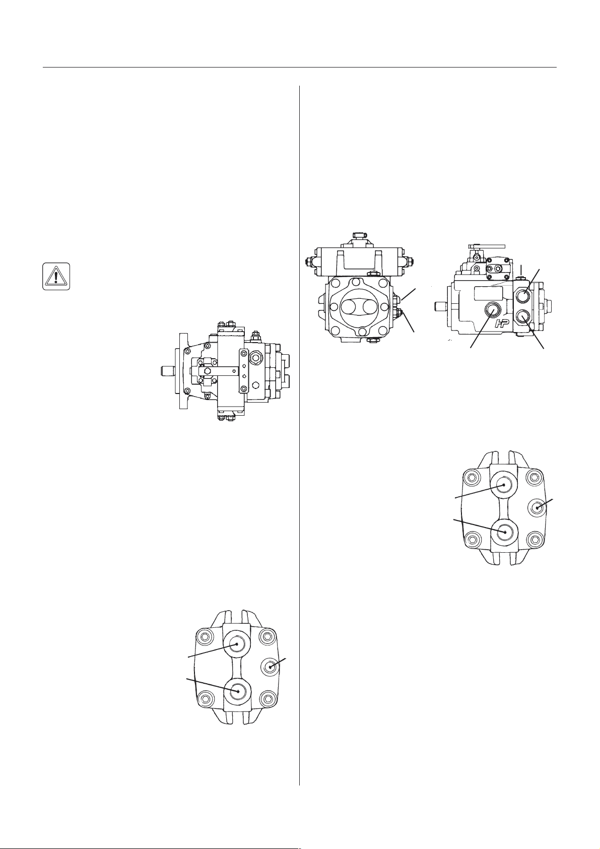
Maintenance
FF
an speed adjustmentan speed adjustment
F
an speed adjustment
FF
an speed adjustmentan speed adjustment
(Bowden cable adjusted pumps only). The boom fan
speed base adjustments are carried out as follows.
A tachometer is required for this job.
1. Fit a piece of light-reflecting tape to the fan wing and
to the tractor P.T.O.
2. Unfold the boom to working position.
3. Set tractor P.T.O. at 540/1000 r.p.m. - check with the
tachometer.
4. Set the fan speed control lever to max. speed.
5. Measure the fan speed with the tachometer. The fan
speed must be 3100 r.p.m.
WARNING! Do not wear loose hanging clothes!
Hold the tachometer firmly in your hands in order
not to be sucked into the fan. DO NOT REMOVE
THE PROTECTION GRID!
6. Turn the swash plate
adjustment screw E
CW to decrease or
CCW to increase the
blower r.p.m.
Remember to tighten
the counter nut.
Repeat 3. and 4. until
the correct setting is
obtained.
7. If the correct fan r.p.m. cannot be reached, the
hydraulic transmission pressure settings must be
checked - see section on Fan transmission pressure
adjustment.
E
T090-0002
the drain hose and tighten.
8. With the tractor P.T.O. at 540/1000 r.p.m. the fan
should rotate at max. revolutions/min.
9. Recheck oil level at tank sight glass.
10.Check vacummeter at the suction filter.
11.Retighten hose connections and check for leaks.
12.Check fan speed and feed pressure adjustments see sections on Fan speed adjustment and Fan
transmission pressure adjustment.
FF
an tran tr
F
FF
T090-0003
T090-0005
A = Pressure port
B = Return port
D = Drain port
P1 = Connector for working pressure measurement
P2 = Connector for feed pressure
R = Adjustment Screw for fed pressure
S = Suction port
ansmission pransmission pr
an tr
ansmission pr
an tran tr
ansmission pransmission pr
S
essuressur
essur
essuressur
P2
R
e adjustmente adjustment
e adjustment
e adjustmente adjustment
P1
D
A
A
B
T090-0002
D
FF
an tran tr
F
FF
If the hydraulic fan transmission has been dismantled, or
pump or motor has been changed, the following priming
procedure must be carried out before starting up the
transmission:
1. Fill the oil reservoir with fresh, clean oil to the top of
2. Fill the pump housing with
3. Check the oil level in the
4. Remove the drain hose D
5. Set the fan r.p.m. at 0,
6. Set the fan speed at 200 r.p.m.
7. After a while the oil will start dripping constantly. Refit
ansmission primingansmission priming
an tr
ansmission priming
an tran tr
ansmission primingansmission priming
the sight glass.
oil through the drain pipe D
which is dismantled at the
tank connection. Reconnect and tighten.
gear box.
from the motor outsidethe
blower housing.
engage the tractor P.T.O. with the engine running idle
- wait a few minutes.
A
B
T090-0002
D
C
B
The transmission feed and working pressure are
checked as follows:
1. Connect a 40 bar (580 p.s.i.) pressure gauge to the
feed pressure connector P2, and a 400 bar (5800
p.s.i.) pressure gauge at the working pressure connector P1.
2. Set the tractor P.T.O. at 540/1000 r.p.m. - check with
tachometer.
3. Set the blower at max. speed.
4. Check the feed and working pressure:
74
GB 14 08 01
Page 75

Maintenance
Feed pressure, P2 15-20 bar (218-290 p.s.i.)
Working pressure, P1, approx.
15 m 160 bar (2321 p.s.i.)
16 m 170 bar (2466 p.s.i.)
18 m 180 bar (2610 p.s.i.)
20 m 190 bar (2755 p.s.i.)
21 m 200 bar (2900 p.s.i.)
24 m 240 bar (3721 p.s.i.)
27 m 240 bar (3721 p.s.i.)
28 m 240 bar (3721 p.s.i.)
Adjust feed pressure if necessary.
Failure to reach feed and working pressure indicates
that the transmission needs overhauling.
GB 14 08 01
75
Page 76

Maintenance
OfOf
f-season storf-season stor
Of
f-season stor
OfOf
f-season storf-season stor
When the spraying season is over, you should devote
some extra time to the sprayer.
If chemical residue is left over in the sprayer for longer
periods, it can reduce the life of the individual components.
OfOf
f-season storf-season stor
Of
f-season stor
OfOf
f-season storf-season stor
To preserve the sprayer intact and to protect the components, carry out following off-season storage program.
1. Clean the sprayer completely - inside and outside - as
described under Cleaning of the sprayer. Make sure
that all valves, hoses and auxiliary equipment have
been cleaned with detergent and flushed with clean
water afterwards, so no chemical residue is left in the
sprayer.
2. Renew possible damaged seals and repair possible
leaks.
3. Empty the sprayer completely and let the pump work
for a few minutes. Operate all valves and handles to
drain as much water off the spraying circuit as possible. Let the pump run until air is coming out of all
nozzles. Remember to drain the rinsing tank also.
aa
gg
ee
a
g
e
aa
gg
ee
aa
gg
e pre pr
ogog
rr
a
g
e pr
aa
gg
e pre pr
og
ogog
amam
r
am
rr
amam
11. All electric plugs and sockets are to be stored in a
dry plastic bag to protect them against damp, dirt and
corrosion.
12.Remove the control boxes and the HARDI PILOT or
HARDI NOVA control box + display from the tractor,
and store them dry and clean (in-house).
13. Wipe hydraulic snap-couplers clean and fit the dust
caps.
14.Apply grease on all hydraulic ram piston rods which
are not fully retracted in the barrel to protect against
corrosion.
15.Chock up the wheels, to prevent moisture damage
and deformation of the tyres. Tyre blacking can be
applied to the tyre walls to preserve the rubber.
16.Drain air brake tank for condensed water.
17. Change hydraulic oil and hydraulic filter as described
in section on Maintenance.
18.To protect against dust the sprayer can be covered by
a tarpaulin. Ensure ventilation to prevent condensation.
4. Pour appr. 50 litre anti-freeze mixture consisting of 1/
3 automotive anti-freeze and 2/3 water into the tank.
5. Engage the pump and operate all valves and functions on the MANIFOLD, operating unit, FILLER etc.
allowing the anti-freeze mixture to be distributed
around the entire circuit. Open the operating unit main
on/off valve and distribution valves so the anti-freeze
is sprayed through the nozzles as well.
The anti-freeze will also prevent O-rings, seals,
diaphragms etc. from drying out.
6. Lubricate all lubricating points according to the
lubricating scheme - regardless of intervals stated.
7. When the sprayer is dry, remove rust from possible
scratches or damages in the paint and touch up the
paint.
8. Remove the glycerine-filled pressure gauges and
store them frost free in vertical position.
9. Apply a thin layer of anti-corrosion oil (e.g. SHELL
ENSIS FLUID, CASTROL RUSTILLO or similar) on
all metal parts. Avoid oil on rubber parts, hoses and
tyres.
10. Fold the boom in transport position and relieve
pressure from all hydraulic functions.
PrPr
ee
paring the sprparing the spr
Pr
e
paring the spr
PrPr
ee
paring the sprparing the spr
After a storage period the sprayer should be prepared
for the next season the following way:
1. Remove the cover
2. Remove the support from the wheel axle and adjust
the tyre pressure.
3. Wipe off the grease from hydraulic ram piston rods.
4. Fit the pressure gauges again. Seal with Teflon tape.
5. Connect the sprayer to the tractor including hydraulics and electrics.
6. Check all hydraulic and electric functions.
7. Empty the tank for remaining anti-freeze.
8. Rinse the entire liquid circuit on the sprayer with
clean water.
9. Fill with clean water and check all functions.
10.Check function of brakes. Please note that brake
power will be reduced until the rust are worn off the
drums. Always brake lightly until the drums are clean.
aa
yy
er fer f
a
aa
or use after storor use after stor
y
er f
or use after stor
yy
er fer f
or use after storor use after stor
aa
gg
a
g
aa
gg
ee
e
ee
76
GB 15 03
Page 77

Fault-finding
FF
ault-fault-f
F
ault-f
FF
ault-fault-f
OperOper
Oper
OperOper
In cases where breakdowns have occurred, the same factors always seem to be the problem:
1. Minor leaks on the suction side of the pump will reduce the pump capacity or stop the suction completely.
2. A clogged suction filter will hinder or prevent suction so that the pump does not operate satisfactorily.
3. Clogged up pressure filters will result in increasing pressure at the pressure gauge but lower pressure at the
nozzles.
4. Foreign bodies stuck in the pump valves with the result that these cannot close tightly against the valve seat. This
reduces pump efficiency.
5. Poorly reassembled pumps, especially diaphragm covers, will allow the pump to suck air resulting in reduced or
no capacity.
6. Hydraulic components that are contaminated with dirt result in rapid wear to the hydraulic system.
Therefore ALWAYS check:
1. Suction, pressure and nozzle filters are clean.
2. Hoses for leaks and cracks, paying particular attention to suction hoses.
3. Gaskets and O-rings are present and in good condition.
4. Pressure gauge is in good working order. Correct dosage depends on it.
5. Operating unit functions properly. Use clean water to check.
6. Hydraulic components are maintained clean.
indinginding
inding
indinginding
aa
tional prtional pr
a
tional pr
aa
tional prtional pr
obob
ob
obob
lemslems
lems
lemslems
TRATRA
CKER damping syCKER damping sy
TRA
CKER damping sy
TRATRA
CKER damping syCKER damping sy
FAULT
Sprayer trails unstable
Front hydraulic rams will
not allow the yoke to turn
when rear rams are
extended/retracted to the
maximum
Rear hydraulic rams are
too tight and vehicle
continues straight ahead
when trying to turn
stemstem
stem
stemstem
PROBABLE CAUSE
Air pockets in the hydraulic
circuit
Hydraulic circuit leaking
Pressure relief valve(s) set too
low
Safety valve incorrectly adjusted
Insufficient counter weight on
front of tractor
Pressure relief valve set too
high
CONTROL/REMEDY
Prime hydraulic circuit
Repair leak, prime
Adjust pressure relief valves
Adjust safety valve
Ad ballast on front of tractor
Adjust pressure relief valves
GB 16 02
77
Page 78

Fault-finding
Liquid syLiquid sy
Liquid sy
Liquid syLiquid sy
FAULT
No spray from boom when
turned on.
Lack of pressure.
stemstem
stem
stemstem
PROBABLE CAUSE
Air leak on suction line.
Air in system.
Suction/pressure filters
clogged.
Incorrect assembly.
CONTROL/REMEDY
Check if suction filter O-ring is sealing.
Check suction tube and fittings.
Check tightness of pump diaphragm and valve
covers.
Fill suction hose with water for initial prime.
Clean filters.
Check yellow suction pipe is not obstructed or
placed too near the tank bottom.
Restrictor nozzle in Self-Cleaning Filter not
fitted.
Safety valve spring for Self-Cleaning Filter not
tight.
Too little distance between yellow suction pipe
and tank bottom.
Pressure dropping.
Pressure increasing
Formation of foam.
Pump valves blocked or worn.
Defect pressure gauge.
Filters clogging.
Nozzles worn.
Tank is air tight.
Sucking air towards end of
tank load.
Pressure filters begining to
clog.
Air is being sucked into system.
Excessive liquid agitation.
Check for obstructions and wear.
Check for dirt at inlet of gauge.
Clean all filters. Fill with cleaner water.
If using powders, make sure agitation is on.
Check flow rate and replace nozzles if it
exceeds 10%.
Check vent is clear.
Lower pump r.p.m.
Clean all filters.
Check tightness / gaskets / O-rings of all
fittings on suction side.
Reduce pump r/min.
Check safety valve for Self-Cleaning Filter is
tight.
Liquid leaks from bottom
of pump.
78
Damaged diaphragm.
Ensure returns inside tank are present.
Use foam damping additive.
Replace. See Changing of valves and diaphragms.
GB 16 02
Page 79

EVEV
C OperC Oper
EV
C Oper
EVEV
C OperC Oper
aa
ting unitting unit
a
ting unit
aa
ting unitting unit
Fault-finding
FAULT
Operating unit not functioning
PROBABLE CAUSE
Blown fuse(s).
Wrong polarity.
Valves not closing properly.
No power.
CONTROL/REMEDY
Check mechanical function of micro-switches.
Use cleaning/lubricating agent if the switch
does not operate freely.
Check motor. 450-500 milli-Amperes max.
Change motor, if over.
Brown - pos. (+). Blue - neg. (-).
Check valve seals for obstructions.
Check micro-switch plate position. Loosen
screws holding plate a
Wrong polarity. Check that brown is pos. (+),
Blue is neg. (-).
Check print plate for dry solders or loose
connections.
Check fuse holder are tight around fuse.
1
/2 turn.
HyHy
drdr
aulic syaulic sy
Hy
dr
aulic sy
HyHy
drdr
aulic syaulic sy
FAULT
Boom slow/eradic.
Ram not functioning.
stem (Tstem (T
stem (T
stem (Tstem (T
rr
actor Operactor Oper
r
actor Oper
rr
actor Operactor Oper
PROBABLE CAUSE
Air in system
Regulation valve incorrectly set
Insufficient hydraulic pressure
Insufficient amount of oil in
tractor reservoir
Restrictor or regulation valve
blocked
aa
ted Hyted Hy
a
ted Hy
aa
ted Hyted Hy
drdr
aulics)aulics)
dr
aulics)
drdr
aulics)aulics)
CONTROL/REMEDY
Loosen ram connection and activate hydraulics
until oil flow has no air in it (not whitish).
Open or close until desired speed is achieved
(clockwise = less speed).
Remember oil must be at operating temperature.
Check output pressure of tractor hydraulics.
Minimum for sprayer is 130 bar.
Check and top up if needed.
Secure boom with S hook.
Dismantle and clean.
GB 16 02
79
Page 80

HyHy
Hy
HyHy
drdr
aulic syaulic sy
dr
aulic sy
drdr
aulic syaulic sy
stem (Dirstem (Dir
stem (Dir
stem (Dirstem (Dir
Fault-finding
ect Acting Hyect Acting Hy
ect Acting Hy
ect Acting Hyect Acting Hy
drdr
aulic Syaulic Sy
dr
aulic Sy
drdr
aulic Syaulic Sy
stem)stem)
stem)
stem)stem)
FAULT
No boom movements
when activated
PROBABLE CAUSE
nsufficient oil pressure
Insufficient oil supply.
Blown fuse.
Bad / corroded electrical
connections
Insufficient power supply.
Defect relay / diodes in junction
box.
Clogged restrictors B or C in
by-pass block.
CONTROL/REMEDY
Check oil pressure - min. 130 bar, max. 160
bar.
Check tractor hydraulic oil level
Oil flow must be min. 10 l/min. and max. 90 l/
min.
Check tractor hydraulic oil level.
Check / replace fuse in junction box.
Check / clean connections, multi plugs etc.
Voltage on activated solenoid valve must be
more than 8 Volts. Use wires of at least 4 mm
for power supply.
Check relays, diodes and soldering at PCB in
junction box
Remove and clean restrictors B and C in by-
pass block (See hydraulic diagram) Change
hydraulic oil + filter
2
Boom lift raises to max.
pos. when tractor
hydraulics are engaged
Oil heats up in Closed
Centre systems
Individual ram does not
move
Wrong polarity.
Wrong oil inlet to by-pass
block.
Back pressure in return line
exceeds 20 bar
By-pass valve 0 does not close
properly
Internal leaks in flow regulator
Clogged restrictor
Check polarity. White pos. (+) Blue neg. (-).
Connect hydraulic snap couplers opposite in
tractor outlets, or engage spool valve lever in
opposite direction
Connect the return line with free flow to hydraulic oil reservoir.
Divide return line in two and lead return oil
back to reservoir via two spool valves.
Check / replace locking clip on by-pass valve 0.
Replace flow regulator O-rings and back-up
rings. Replace flow regulator.
Dismantle and clean restrictor
80
GB 16 02
Page 81

HyHy
Hy
HyHy
drdr
aulic faulic f
dr
aulic f
drdr
aulic faulic f
an tran tr
ansmissionansmission
an tr
ansmission
an tran tr
ansmissionansmission
Fault-finding
FAULT
Max. revolutions cannot be
obtained
Noisy fan transmission
Formation of foam in oil
tank
PROBABLE CAUSE
Tractor P.T.O. speed is lower
than 540 r.p.m. (reading failure
on tractometer)
Feed pressure is too low
Max. fan r.p.m. is not adjusted
correctly (models with bowden
cable adjustment only)
Pump/motor is worn
Wrong oil quality (foam)
Feed pressure too low
Oil filter clogged (vacummeter
indicator in red area)
Pump/motor is worn
Wrong oil quality
CONTROL/REMEDY
Check tractors P.T.O. r.p.m.
Check tractometer
Adjust feed pressure to correct setting
Adjust the max. fan r.p.m.
Get transmission checked by your HARDI
dealer
Change oil to correct quality
Adjust feed pressure
Change oil filter
Get the fan transmission checked by your
HARDI dealer
Change the oil to correct quality
Fan speed will not stay at
adjusted level
Fan r.p.m. control does not
start up
Oil leaks from pump/motor
shaft seal (seal pressed
out)
Mixture of hydraulic oil and
other quality (e.g. universal oil)
Oil change interval not kept
Leak on the pump suction line
No signal from speed sensor at
the fan
Bad connections
Fuse blown
Drain hoses from motor/pump
housing is blocked
Too much pressure in pump/
motor housing (pump/motor
worn)
Change the oil to correct quality
Change the oil to fresh, clean oil of correct
quality
Check hydraulic pump suction line for leaks
Check the wire connection between sensor
and actuator for damages
Check the wire connection between sensor
and actuator for damages
Check power supply and fuse
Check the drain hose(s) for bendings, damages, and proper attachment
Get the transmission checked by your HARDI
dealer
GB 16 02
81
Page 82

Fault-finding
EmerEmer
Emer
EmerEmer
TT
T
TT
In case of power failure, the boom can be operated
manually:
1. Put the tractor spool valve control lever in neutral
2. Close the cartridge valve A on the hydraulic distribu-
T112-0004x
gg
encenc
g
enc
gg
encenc
he boomhe boom
he boom
he boomhe boom
position.
tion block.
y opery oper
y oper
y opery oper
aa
tion oftion of
a
tion of
aa
tion oftion of
the spr the spr
the spr
the spr the spr
aa
a
aa
yy
erer
y
er
yy
erer
A
3. Activate the tractor spool valve control lever.
4. The boom can now be operated by pressing the
individual buttons on the solenoid valves.
EC operEC oper
EC oper
EC operEC oper
In case of power failure it is possible to operate all
functions of the operating unit manually. First disconnect
the multi plug from the control box. Now manually turn
the emergency control knobs.
The problem may be due to a blown fuse. An extre fuse
is placed inside the box.
Fuse type: 6.3 A
aa
ting unitting unit
a
ting unit
aa
ting unitting unit
T020-0024
Remember to reset the system to original setting.
Steering drSteering dr
Steering dr
Steering drSteering dr
1. Put the tractor spool valve control lever in neutral
position.
2. Close the cartridge valves A and B on the hydraulic
distribution block.
3. By means of the tractor spool valve control lever, the
drawbar can now be centred.
aa
wbar (ifwbar (if
a
wbar (if
aa
wbar (ifwbar (if
f f
itted)itted)
f
itted)
f f
itted)itted)
A
T112-0004x
Remember to reset the system to original setting.
B
T199-0004
CauseCause
Cause
CauseCause
The problem may be due to a blown fuse. One spare
fuse is located inside the junction box.
82
GB 17 03
Page 83
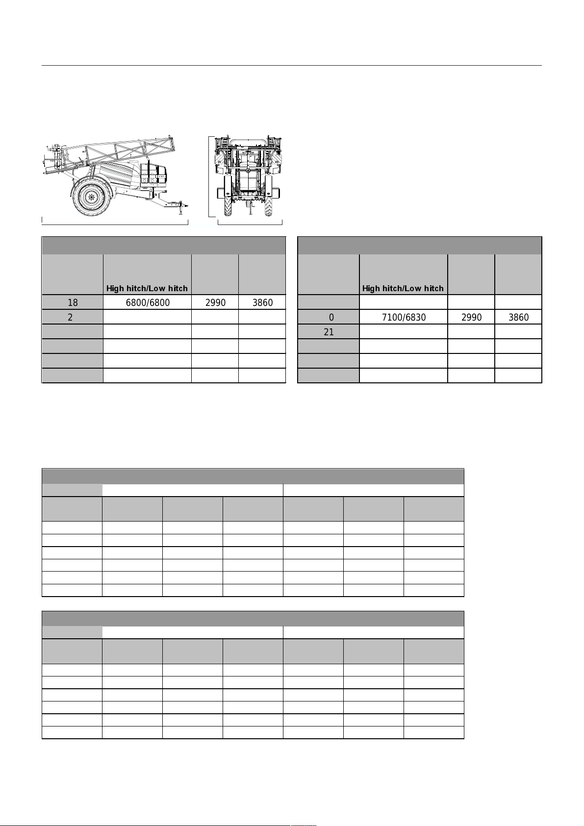
TT
ecec
hnical specifhnical specif
T
ec
hnical specif
TT
ecec
hnical specifhnical specif
OvOv
erer
all dimensionsall dimensions
Ov
er
all dimensions
OvOv
erer
all dimensionsall dimensions
T142-0027x
Technical specifications
icaica
tionstions
ica
tions
icaica
tionstions
C
AB
&0 SOXV+$<+$=
%RRPZLGWK $ % &
P PP PP PP
+LJKKLWFK/RZKLWFK
18 6800/6800 2990 3860
20 6800/6800 2990 3860
21 6800/6800 2990 3860
24 6800/6800 2990 3860
27 6800/6800 2990 3860
28 6800/6800 2990 3860
All measurements are in mm and are based on maschines equipped with wheel size 12.4 x R46.
The length (A) is based on the short version of the drawbar extension. Additional length for long version:
CM 2200/2800: + 350 mm
CM 3200/4200: + 450 mm
WW
eighteight
W
eight
WW
eighteight
&0 SOXV+$<+$=
%RRPZLGWK $ % &
P PP PP PP
+LJKKLWFK/RZKLWFK
18 7100/6830 2990 3860
20 7100/6830 2990 3860
21 7100/6830 2990 3860
24 7100/6830 2990 3860
27 7100/6830 2990 3860
28 7100/6830 2990 3860
&0SOXV+$<+$=
(PSW\ )XOO
%RRPZLGWK $[OHORDG 'UDZEDU 2ZQZHLJKW $[OHORDG 'UDZEDU 7RWDOZHLJKW
P NJ ORDGNJ NJ NJ ORDGNJ NJ
18 3310 654 3964 5377 1209 6586
20 3320 659 3979 5387 1214 6601
21 3333 666 3999 5401 1220 6621
24 3360 679 4039 5427 1234 6661
27 3416 708 4124 5483 1263 6746
28 3425 714 4139 5492 1269 6761
&0SOXV+$<+$=
(PSW\ )XOO
%RRPZLGWK $[OHORDG 'UDZEDU 2ZQZHLJKW $[OHORDG 'UDZEDU 7RWDOZHLJKW
P NJ ORDGNJ NJ NJ ORDGNJ NJ
18 3329 660 3989 5754 1302 7056
20 3339 665 4004 5764 1307 7071
21 3353 671 4024 5777 1314 7091
24 3380 684 4064 5804 1327 7131
27 3435 714 4149 5860 1356 7216
28 3444 720 4164 5869 1362 7231
All weights are approximate values and are based on machines equipped with rinsing tank, clean water tank, HARDI FILLER and suspended
axle.
GB 18 01 07
83
Page 84

Technical specifications
WW
eighteight
W
eight
WW
eighteight
&0SOXV+$<+$=
(PSW\ )XOO
%RRPZLGWK $[OHORDG 'UDZEDU 2ZQZHLJKW $[OHORDG 'UDZEDU 7RWDOZHLJKW
P NJ ORDGNJ NJ NJ ORDGNJ NJ
18 3577 598 4175 6886 1535 8421
20 3588 602 4190 6897 1538 8435
21 3603 607 4210 6912 1543 8455
24 3633 617 4250 6942 1553 8495
27 3697 638 4335 7006 1575 8581
28 3707 643 4350 7016 1579 8595
&0SOXV+$<+$=
(PSW\ )XOO
%RRPZLGWK $[OHORDG 'UDZEDU 2ZQZHLJKW $[OHORDG 'UDZEDU 7RWDOZHLJKW
P NJ ORDGNJ NJ NJ ORDGNJ NJ
18 3609 606 4215 7730 1535 9265
20 3620 610 4230 7742 1538 9280
21 3636 614 4250 7757 1543 9300
24 3666 624 4290 7787 1553 9340
27 3729 646 4375 7850 1575 9425
28 3740 650 4390 7861 1579 9440
All weights are approximate values and are based on machines equipped with rinsing tank, clean water tank, HARDI FILLER and suspended
axle.
For SELF TRACK models the values in above tables must be increased:
+ 100 kg on Drawbar and Total weights
For COMMANDER models without suspended axle, subtract:
COMMANDER 2200/2800 - 220 kg (own weight)
COMMANDER 3200/4200 - 250 kg (own weight)
Ground clearance (under axle):
COMMANDER 2200/2800 without suspension: appr. 700 mm with suspension: appr. 600 mm
COMMANDER 3200/4200: without suspension: appr. 700 mm with suspension: appr. 750 mm
3723RZHUFRQVXPSWLRQ
%RRPVL]H N: +S
18 m 34 46
20 m 42 57
21 m 42 57
24 m 54 73
27 m 54 73
28 m 54 73
The power consumption is stated at a working pressure of 10 bar.
84
GB 18 01 07
Page 85

Technical specifications
Pump caPump ca
Pump ca
Pump caPump ca
pacitypacity
pacity
pacitypacity
Pump 363/10.0 (540 r.p.m.)
repnoitatoR
.nim
rabnim/lyticapaC
037701141871491112
227501041571981702
417301931271681502
607201831961481302
0186001531661281002
516689231461871791
002 003 004 005 045 006
rab51:erusserp.xaMgk5.25:thgieWm0.0:thgiehnoitcuS
Pump 363/5.5 (1000 r.p.m.)
repnoitatoR
.nim
rabnim/lyticapaC
0-1628301321441461681102
2-9597001911041061971191
4-858789711831551671881
6-756769511431351371681
01-554749211031841861081
51-352798801621441361471
002 003 004 005 006 007 008 009 0001
rab51:erusserp.xaMgk6.25:thgieWm0.0:thgiehnoitcuS
Pump 463/10.0 (540 r.p.m.)
repnoitatoR
.nim
rabnim/lyticapaC
0901651702752672503
2301251202252072992
4101941891642562592
699641591242362982
0149241291632652282
5119631481032842672
002 003 004 005 045 006
rab51:erusserp.xaMgk5.66:thgieWm0.0:thgiehnoitcuS
Pump 463/5.5 (1000 r.p.m.)
repnoitatoR
.nim
rabnim/lyticapaC
01698911841871602332372503
26548311041861791222252872
44528801731261091612442372
62587501131851581112932962
019447001621151871202922752
51640759021541171591912642
002 003 004 005 006 007 008 009 0001
rab51:erusserp.xaMgk5.66:thgieWm0.0:thgiehnoitcuS
GB 18 01 07
85
Page 86

Technical specifications
FF
ilterilter
F
FF
Filter gauze width
30 mesh: 0.58 mm 50 mesh: 0.30 mm
80 mesh: 0.18 mm 100 mesh: 0.15 mm
TT
T
TT
Operating temperature range:
2° to 40° C. (36°F to 104°F)
Operating pressure for safety valve:
15 bar (220 psi)
Max. pressure on the pressure manifold:
20 bar (290 psi)
Max. pressure on the suction manifold:
7 bar (100 psi)
BrBr
Br
BrBr
Max. wear rates on brake components, mm (in):
Max. drum diameter A 302 (11.8897) 402 (15.8388)
Min. lining thickness B 2.0 (0.07874) 4.0 (0.15748)
s and nozzless and nozzles
ilter
s and nozzles
ilterilter
s and nozzless and nozzles
emperemper
emper
emperemper
akak
ak
akak
eses
es
eses
aa
a
aa
turtur
tur
turtur
e and pre and pr
e and pr
e and pre and pr
essuressur
essur
essuressur
2200/2800 3200/4200
e re r
e r
e re r
angang
ang
angang
eses
es
eses
ConCon
vv
erer
v
vv
er
erer
sion fsion f
sion f
sion fsion f
Con
ConCon
All units used in this manual are SI units. In some
occasions Imperial units are used. Use following factors
to convert SI units to Imperial units:
Weight kg lb. x 2.205
Surface area ha acres x 2.471
Length cm in x 0.394
Velocity km/h mile/h x 0.621
Quantities/area l/ha gal (Imp.) x 0.089
Volume ml fl. oz (Imp.) x 0.0352
Pressure bar lb./in
Temperature °C °F (°C x 1.8) +
Power kW hp x 1.341
Torque Nm lbft x 0.74
actoractor
actor
actoractor
ss
, SI to Imperial units, SI to Imperial units
s
, SI to Imperial units
ss
, SI to Imperial units, SI to Imperial units
SI unit Imperial Factor
unit
m ft x 3.281
m yd x 1.094
km mile x 0.621
km/h m/s x 0.277
/acre
l Imp. pt. x 0.568
l gal (Imp.) x 0.22
2
(p.s.i.)
x 14.504
32
Hydraulic brakes
Max. hydraulic pressure: 150 bar (2176 p.s.i.)
Air brakes, single line:
Air pressure, relieved brakes: 5.3 - 5.6 bar
Air pressure drop to activate: 0.8 - 1.3 bar
Air brakes, dual line
Load apportioning valve pressure settings:
Relieved: 0 bar
Empty: 1.6 bar (23.2 p.s.i.)
Half: 3.4 bar (49.3 p.s.i.)
Full: Air tank pressure
MaMa
terials and rterials and r
Ma
terials and r
MaMa
terials and rterials and r
Tank: HDPE
Hoses: PVC
Valves: mainly glass-filled PA.
Fittings: PA
Disposal of the sprayer
When the equipment has completed its working life, it
must be thoroughly cleaned. The tank, hose and synthetic fittings can be incinerated at an authorised disposal plant. The metallic parts can be scrapped. Always
follow local legislation regarding disposal.
ecec
ec
ecec
yy
cc
lingling
y
c
ling
yy
cc
lingling
Electrical connectionsElectrical connections
Electrical connections
Electrical connectionsElectrical connections
Rear lights
Position Wire colour
1. LH direction indicator Yellow
2. Free Blue
3. Frame White
4. RH direction indicator Green
5. RH rear position lamp Brown
6. Stop lamps Red
7. LH rear position lamp Black
The wiring is in accordance with ISO 1724.
6
5
1
2
7
3
4
86
GB 18 01 07
Page 87

Technical specifications
Electrical connections fElectrical connections f
Electrical connections f
Electrical connections fElectrical connections f
20 poled plug with cable
or EVor EV
or EV
or EVor EV
C operC oper
C oper
C operC oper
aa
ting unitting unit
a
ting unit
aa
ting unitting unit
1XPEHURIGLVWULEXWLRQYDOYH
:LUHQXPEHURUFRORXUFRGH
8 G/Y
9 9 13 9 9 10 10 14 10 10
8 G/Y G/Y G/Y 11 11 15 G/Y
77 1717
6611 221616
55331 2441515
445 3 4 61414
33755 6681313
2297 8101212
1 1 11 12 11 11
*< JUHHQ\HOORZ
EVEV
CC
EV
C
EVEV
CC
T279-0010
Electrical cElectrical c
Electrical c
Electrical cElectrical c
harhar
har
harhar
t (EVt (EV
t (EV
t (EVt (EV
C)C)
C)
C)C)
V VV V
armatur EC 2B(L)
Number of distribution valves
2/3/4 5/6 7 8
Valve Wire number or color code
V1 1-2 1-2 1-11 1-11
V2 3-4 3-4 2-12 2-12
V3 5-6 5-6 3-13 3-13
V4 7-8 7-8 4-14 4-14
V5 9-10 5-15 5-15
V6 11-12 6-16 6-16
V7 7-17 7-17
REG 9-10 13-14 9-10 9-10
V8 ? ? ? 8-G/Y
G/Y = Green/Yellow
T192-0037.dxf
The EVC operating unit fulfils the EC noise reduction
standards.
GB 18 01 07
87
Page 88

Technical specifications
InstallaInstalla
Installa
InstallaInstalla
tion instrtion instr
tion instr
tion instrtion instr
uction fuction f
uction f
uction fuction f
or boom and wor boom and w
or boom and w
or boom and wor boom and w
oror
k lightk light
or
k light
oror
k lightk light
88
T162-0108
GB 18 02 04
Page 89
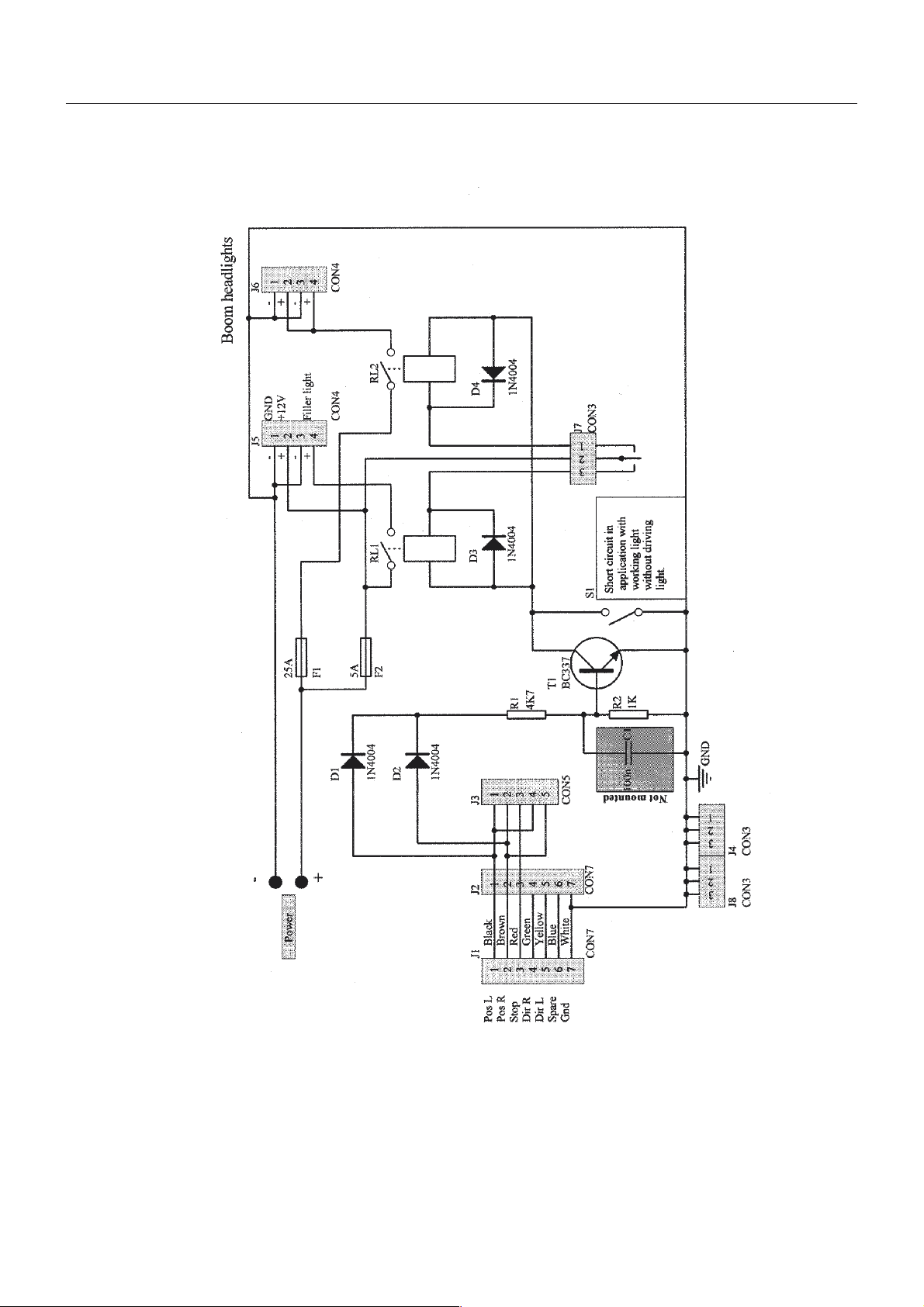
Technical specifications
Electrical specifElectrical specif
Electrical specif
Electrical specifElectrical specif
icaica
ica
icaica
tions ftions f
tions f
tions ftions f
or Boom and Wor Boom and W
or Boom and W
or Boom and Wor Boom and W
oror
k lightk light
or
k light
oror
k lightk light
T053-0016
GB 18 02 04
89
Page 90

Technical specifications
Boom hyBoom hy
Boom hy
Boom hyBoom hy
Illustrations still missing
drdr
aulic caulic c
dr
aulic c
drdr
aulic caulic c
harhar
har
harhar
tsts
ts
tsts
90
GB 18 02 04
Page 91

Subject IndeSubject Inde
Subject Inde
Subject IndeSubject Inde
xx
x
xx
A
Air activated brakes 18
Air assistance 43
Air brake filters 63
Air in system 78
Air speed 43
Air technique 43
Air volume 43
Altering track gauge 15
Angling of air and liquid 43
Anti-freeze 76
Application zone 6
AXIAL connection 71
B
Ball valve 37
Ballast 77
Black disc 32
Blower adjustment 43
Blown fuse 82
Boom light 26
Boom slow/eradic 79
Brakes 18
Break-away 64
C
CaCl2 20
Centre rim 15
Chemicals 38, 42
Circuit leak 77
Clean water tank 36
Clean zone 6
Cleaning the sprayer 49
Colour codes 43
Cone 68
Connection box 26
Conversion factors 86
Counter weight 20
Crop protection Kit 27
D
D.A.H. system 16
Damping pressure setting 70
Diaphragm 68
Disconnecting 29
Disposal of pesticides 49
Distribution block 16
Drawbar 9
Drawbar extension 9
Driving Technique 23
Dual-line brakes 19
E
EC Declaration 4
EVC operating unit 34, 36, 87
Emergency brake 18
Emergency operation of the sprayer 82
Expansion bottle 60, 63
F
Fan speed 43
Fast Filling Device 34
Filling 33
Filling of chemicals 38
Filling of water 33
Filter gauze 58
Filters 7, 37
Fittings 71
Fixed drawbar 10
Formation of foam 78
Frame 7
Front Locker 25
Function diagram 32
Fuse 82
Fuse type 82
G
Green disc 32
Guide rods 64
H
HARDI FILLER 38
HARDI-MATIC 7
Hitch (ISO 5692) 9
Hub flange 15
Hydraulic activated brakes 18
Hydraulic brakes 63
Hydraulic circuit 63
Hydraulic systems 16
I
Identification plates 7
Imperial units 86
In-Line filter 58
Inner section 64
J
Junction box 82
L
Lack of pressure. 78
Ladder 25
91
Page 92

Large storage Locker 25
Level indicator 71
Lifting points 8
Liquid chemicals 38
Liquid leaks 78
Liquid-filled tyres 20
Load Sensing 16
M
Maintenance 49
MANIFOLD SYSTEM 32
Max. pressure 86
Maximum track width 14
Minimum track width 14
Mudguard 28
Multi plug 82
N
Pump valves 68
PVC sheet 27
Q
Quick coupler 35
R
RADIAL connection 71
Ram not functioning 79
Rear lights 25, 86
Recycling 86
Remote pressure gauge 37
Replace tyres 73
Restrictor 37
Rinsing nozzles 40
Rinsing tank 35, 40
Rinsing tank drain valve 42
No spray from boom 78
Nominal contents 7
Nozzle filters 58
Nozzle tube 71
Nozzles 86
O
O-ring 71
Off-season storage 76
Oil heats up 80
Operating pressure 86
Operating temperature 86
Operating unit 7
Operational problems 77
Operator safety 5
Outer section 64
P
P.T.O. shaft 7, 11
Parking brake 18, 29, 62
Pendulum return spring and cables 64
Personal protection 42
Pesticide washings 49
Powder chemicals 39
Power failure 82
Power supply 17
Pressure gauge 37, 43
Pressure increasing 78
Pressure range 86
Pressure valve 32
Product Identification Certificate 4
Protection film 8
Protective clothing 49
Pump 7
Pump capacity 85
S
Safe sprayers 49
Safety valve 77
Selector switch 26
SELF TRACK 10, 23
Self-cleaning filter 37
Shipping package label 4
Shock absorbers 70
SI 86
Single-line brakes 19
Small storage Locker 25
Soap dispenser 26
Sprayer trails unstable 77
Spraying circuit 58
Stability 15
STEER TRACK 23
STEERING drawbar 10
Stop wedges 29
Strawdivider 27
Suction Filling Device 34
Suction filter 58
Suction quick coupler 41
Suction valve 32
Support leg 29
Swivel type 9
T
Tank 7
Tank drain valve 41
Tank lid 33
Technical Residue 41
Temperature 86
The work light 26
TRAIL CONTROL 10
Transmission shaft 11
92
Page 93

Transmission shaft support 10, 29
Transport lock 22
Tyre 73
Tyre pressure 60
Tyre safety 82
U
Unloading 8
W
Water sensitive paper 45
Wear bush 69
Wear rates 86
Wheel bearings 62
Wheel bolts 60
Wheel brake cover 27
Wiring 21
Working zone 6
Y
Yellow MANIFOLD valve 37
Z
Zugmaul 9
93
Page 94

94
 Loading...