

Page 1
COMMANDER
TWIN FORCE
Original
Instruction book
67035300-100 - Version 1.00
GB - 05.2013
www.hardi-international.com
Page 2

We congratulate you for choosing a HARDI plant protection product. The reliability and
efficiency of this product depend upon your care. The first step is to carefully read and pay
attention to this instruction book. It contains essential information for the efficient use and
long life of this quality product.
This book covers updated COMMANDER models, also known as COMMANDER ‘11
series.
The original instruction book is approved and published in English. All other languages are translations of the
original. In the event of any conflicts, inaccuracies or deviations between the English original and other languages
the English version shall prevail.
Illustrations, technical information and data in this book are to the best of our belief correct at the time of printing.
As it is HARDI INTERNATIONAL A/S policy permanently to improve our products, we reserve the right to make
changes in design, features, accessories, specifications and maintenance instructions at any time and without
notice.
HARDI INTERNATIONAL A/S is without any obligation in relation to implements purchased before or after such
changes.
HARDI INTERNATIONAL A/S cannot undertake any responsibility for possible omissions or inaccuracies in this
publication, although everything possible has been done to make it complete and correct.
As this instruction book covers more models and features or equipment, which are available in certain countries
only, please pay attention to paragraphs dealing with precisely your model.
Published and printed by HARDI INTERNATIONAL A/S
Page 3

Table of Contents
1 - EC Declaration
EC Declaration of Conformity ................................................................................................................9
2 - Safety notes
Operator safety ...................................................................................................................................11
Symbols ..................................................................................................................................................................................................................... 11
Precautions ............................................................................................................................................................................................................. 11
Label explanation ............................................................................................................................................................................................... 12
3 - Description
General info .........................................................................................................................................15
View ............................................................................................................................................................................................................................. 15
View ............................................................................................................................................................................................................................. 16
Identification plates ........................................................................................................................................................................................... 16
Roadworthiness ................................................................................................................................................................................................... 16
Sprayer use .............................................................................................................................................................................................................. 17
Frame .......................................................................................................................................................................................................................... 17
Tanks and equipment ...................................................................................................................................................................................... 17
Liquid system ......................................................................................................................................18
Pump .......................................................................................................................................................................................................................... 18
Valves and symbols ............................................................................................................................................................................................ 18
DynamicFluid4 pressure regulation ........................................................................................................................................................ 19
Clean water tank .................................................................................................................................................................................................. 21
Rinsing tank ............................................................................................................................................................................................................ 21
Filters ........................................................................................................................................................................................................................... 21
EasyClean filter ...................................................................................................................................................................................................... 21
CycloneFilter .......................................................................................................................................................................................................... 22
TurboFiller ................................................................................................................................................................................................................ 23
Diagram - Basic liquid system ..................................................................................................................................................................... 24
Diagram - Liquid system with optional extras .................................................................................................................................. 25
Diagram - Intelligent liquid system with optional extras ........................................................................................................... 26
TWIN Air technique ..............................................................................................................................27
General info ............................................................................................................................................................................................................ 27
Boom ...................................................................................................................................................28
Boom and terminology ................................................................................................................................................................................... 28
SetBox controls ..................................................................................................................................................................................................... 29
Grip controls ........................................................................................................................................................................................................... 29
Hydraulic systems ...............................................................................................................................30
Hydraulic blocks ................................................................................................................................................................................................... 30
Equipment ...........................................................................................................................................32
SafeTrack ................................................................................................................................................................................................................... 32
Driving technique for SafeTrack ................................................................................................................................................................. 32
Platform ..................................................................................................................................................................................................................... 33
Drawbars .................................................................................................................................................................................................................. 33
Hydraulic support leg ....................................................................................................................................................................................... 34
Tank level indicator ............................................................................................................................................................................................ 35
External Cleaning Device (optional) ........................................................................................................................................................ 35
Nozzle pressure gauge .................................................................................................................................................................................... 35
SafetyLocker ........................................................................................................................................................................................................... 36
ChemLocker ........................................................................................................................................................................................................... 36
Night Spraying Light (optional) ................................................................................................................................................................. 37
4 - Sprayer setup
General info .........................................................................................................................................39
Unloading the sprayer from the truck ................................................................................................................................................... 39
Pulling the sprayer at the tie down hooks .......................................................................................................................................... 39
Before putting the sprayer into operation .......................................................................................................................................... 39
Hydraulic support leg (option for CM 3300/4500) ......................................................................................................................... 40
Jack up the sprayer ............................................................................................................................................................................................ 40
3
Page 4

Transmission shaft ..............................................................................................................................41
Operator safety ..................................................................................................................................................................................................... 41
P.T.O. installation .................................................................................................................................................................................................. 41
Mechanical connections ......................................................................................................................42
Hose package support ..................................................................................................................................................................................... 42
SafeTrack potentiometer connection .................................................................................................................................................... 42
Hydraulic systems ...............................................................................................................................43
General info ............................................................................................................................................................................................................ 43
Requirements - tractor (HAY model) ...................................................................................................................................................... 43
Requirements - tractor (HAZ model) ...................................................................................................................................................... 43
Open centre hydraulics (optional) ........................................................................................................................................................... 44
Electrical connections ..........................................................................................................................45
Installation of control unit brackets ......................................................................................................................................................... 45
Road safety kit ....................................................................................................................................................................................................... 45
Power supply ......................................................................................................................................................................................................... 46
Speed transducer for sprayer ...................................................................................................................................................................... 47
Liquid system ......................................................................................................................................48
CycloneFilter .......................................................................................................................................................................................................... 48
Boom ...................................................................................................................................................49
Damping adjustment ....................................................................................................................................................................................... 49
Boom folding speed adjustment .............................................................................................................................................................. 49
Boom folding speed adjustment - 32-36 m boom only ............................................................................................................. 49
TWIN Air technique ..............................................................................................................................50
Adjusting the air assistance .......................................................................................................................................................................... 50
Setting of air speed, rules of thumb ........................................................................................................................................................ 50
Angling of air and liquid, rules of thumb ............................................................................................................................................. 51
Water sensitive paper ....................................................................................................................................................................................... 51
Track gauge, axles and wheels ............................................................................................................52
Altering the track width .................................................................................................................................................................................. 52
Turning rim ............................................................................................................................................................................................................. 52
Counter weight .................................................................................................................................................................................................... 53
Brakes ..................................................................................................................................................54
Emergency and parking brake .................................................................................................................................................................... 54
Hydraulic activated brakes ............................................................................................................................................................................ 54
Air activated brakes (optional) .................................................................................................................................................................... 55
Single-line brakes (optional) ......................................................................................................................................................................... 55
Dual-line brakes (optional) ............................................................................................................................................................................ 55
5 - Operation
General info .........................................................................................................................................57
Environmental info ............................................................................................................................................................................................ 57
Boom ...................................................................................................................................................58
Safety info ................................................................................................................................................................................................................ 58
Manoeuvring of the boom - HAY ............................................................................................................................................................. 58
Manoeuvring of the boom - HAZ ............................................................................................................................................................. 59
Hydraulic slanting control ............................................................................................................................................................................. 60
Z-models .................................................................................................................................................................................................................. 60
Boom tilt function ............................................................................................................................................................................................... 60
2/3 boom width ................................................................................................................................................................................................... 60
Half boom width ................................................................................................................................................................................................. 60
Hydraulic breakaway function .................................................................................................................................................................... 60
TWIN Air technique ..............................................................................................................................61
TWIN operation .................................................................................................................................................................................................... 61
Liquid system ......................................................................................................................................62
Filling/washing location requirements ................................................................................................................................................. 62
Filling of water ...................................................................................................................................................................................................... 62
Filling through tank lid .................................................................................................................................................................................... 63
Filling of rinsing tank ......................................................................................................................................................................................... 63
Filling of clean water tank .............................................................................................................................................................................. 63
4
Page 5

External Filling Device ...................................................................................................................................................................................... 64
Safety precautions - crop protection chemicals .............................................................................................................................. 65
Filling chemicals through tank lid ............................................................................................................................................................ 65
Filling liquid chemicals by HARDI TurboFiller ................................................................................................................................... 66
Filling powder chemicals by HARDI TurboFiller .............................................................................................................................. 67
TurboFiller rinsing ............................................................................................................................................................................................... 68
Operating the control units while spraying ....................................................................................................................................... 69
Before returning to refill the sprayer ....................................................................................................................................................... 70
Agitation before resuming a spray job .................................................................................................................................................. 70
Parking the sprayer ............................................................................................................................................................................................ 70
Quick reference - Operation ......................................................................................................................................................................... 71
Cleaning ...............................................................................................................................................72
General info ............................................................................................................................................................................................................ 72
Quick reference - Cleaning ............................................................................................................................................................................ 73
Cleaning and maintenance of filters ....................................................................................................................................................... 74
Use of rinsing tank and rinsing nozzles ................................................................................................................................................. 74
A. Full internal rinsing ....................................................................................................................................................................................... 74
B. External cleaning ............................................................................................................................................................................................ 75
C. Rinsing spraying circuit without diluting main tank content ............................................................................................ 76
Full internal cleaning (Soak wash) ............................................................................................................................................................ 76
PrimeFlow - manual cleaning ..................................................................................................................................................................... 78
Use of detergents ............................................................................................................................................................................................... 78
Technical residue ................................................................................................................................................................................................ 78
Using the drain valve ........................................................................................................................................................................................ 78
Pressure draining (optional) ......................................................................................................................................................................... 79
6 - Maintenance
Lubrication ..........................................................................................................................................81
General info ............................................................................................................................................................................................................ 81
Recommended lubricants ............................................................................................................................................................................. 81
P.T.O. lubrication & oiling plan .................................................................................................................................................................... 81
Boom lubrication and oiling plan ............................................................................................................................................................. 82
Boom lubrication and oiling plan (32-36 m) ...................................................................................................................................... 83
Trailer/ParaLift lubrication & oiling plan ................................................................................................................................................ 84
Service and maintenance intervals .....................................................................................................85
10 hours service - Cyclone Filter ................................................................................................................................................................ 85
10 hours service - EasyClean filter ............................................................................................................................................................. 85
10 hours service - In-Line filter (not PrimeFlow) .............................................................................................................................. 86
10 hours service - Spraying circuit ............................................................................................................................................................ 86
10 hours service - Brakes (Standard for CM 5500 and 7000) .................................................................................................... 86
10 hours service - Brakes air tank (optional) ....................................................................................................................................... 86
10 hours service - Lubricate boom and centre ................................................................................................................................ 86
10 hours service - Hydraulic oil level ....................................................................................................................................................... 87
10 hours service - Gearbox oil level ......................................................................................................................................................... 87
50 hours service - Transmission shaft ..................................................................................................................................................... 87
50 hours service - Wheel nuts ..................................................................................................................................................................... 87
50 hours service - Air brakes (optional) ................................................................................................................................................. 87
50 hours service - Tyre pressure ................................................................................................................................................................. 87
50 hours service - Gearbox bolts ............................................................................................................................................................... 88
100 hours service - Check/tighten steering ....................................................................................................................................... 88
250 hours service - Readjustment of the boom .............................................................................................................................. 89
250 hours service - Wheel bearings ......................................................................................................................................................... 89
250 hours service - Hydraulic circuit ....................................................................................................................................................... 89
250 hours service - Hoses and tubes ...................................................................................................................................................... 89
250 hours service - Inspect parking brake (optional) ................................................................................................................... 90
250 hours service - Air brake filters (optional) ................................................................................................................................... 90
250 hours service - Brake adjustment (optional) ............................................................................................................................. 90
250 hours service - Hydraulic brakes (optional) ............................................................................................................................... 91
500 hours service - Hydraulic oil filter .................................................................................................................................................... 91
1000 hours service - Wheel bearings and brakes ............................................................................................................................ 91
5
Page 6

Occasional maintenance ......................................................................................................................93
Pump valves and diaphragms renewal ................................................................................................................................................. 93
Level indicator wire renewal ........................................................................................................................................................................ 94
Level indicator adjustment ........................................................................................................................................................................... 94
Drain valve seal renewal ................................................................................................................................................................................. 94
Adjustment of 3-way valve ........................................................................................................................................................................... 95
Feed pipe snap-lock assembly ................................................................................................................................................................... 95
Feed pipe clamp assembly ........................................................................................................................................................................... 96
Opening the cable trays ................................................................................................................................................................................. 96
Readjustment boom - general info ......................................................................................................................................................... 97
Alignment of centre and inner wing sections .................................................................................................................................. 97
Alignment of inner and 1st outer wing sections ............................................................................................................................ 98
Alignment of inner and 1st outer wing sections (32-36 m) ..................................................................................................... 98
Breakaway section adjustment .................................................................................................................................................................. 98
Breakaway section adjustment (32-36m) ............................................................................................................................................ 99
Hydraulic slanting control adjustment .................................................................................................................................................. 99
Hydraulic slanting control adjustment (32-36m) ............................................................................................................................ 99
Wing tilt adjustment .......................................................................................................................................................................................100
Spring arrangement (32-36 m only) ......................................................................................................................................................100
Wear bushing renewal on boom lift .....................................................................................................................................................100
Change of bulbs ................................................................................................................................................................................................101
Wear bushing renewal on steering .......................................................................................................................................................101
Shield renewal on transmission shaft ...................................................................................................................................................101
Replacement of transmission shaft cross journals .......................................................................................................................101
Safety valve activation ...................................................................................................................................................................................101
Change of tyre ....................................................................................................................................................................................................102
Fan transmission priming ............................................................................................................................................................................102
Fan transmission pressure adjustment ...............................................................................................................................................103
Off-season storage ........................................................................................................................... 104
Off-season storage program ......................................................................................................................................................................104
7 - Fault finding
Operational problems ...................................................................................................................... 107
General info ..........................................................................................................................................................................................................107
Liquid system .......................................................................................................................................................................................................108
Hydraulic system - Z model ........................................................................................................................................................................109
Hydraulic system - Y model ........................................................................................................................................................................109
Hydraulic fan transmission ..........................................................................................................................................................................110
Controller fault codes .....................................................................................................................................................................................111
Mechanical problems ....................................................................................................................... 112
Emergency operation - Liquid system .................................................................................................................................................112
Emergency operation - EasyClean filter ..............................................................................................................................................112
8 - Technical specifications
Dimensions ....................................................................................................................................... 113
General info ..........................................................................................................................................................................................................113
Overall dimensions ..........................................................................................................................................................................................113
Weight .....................................................................................................................................................................................................................114
Wheel and axle dimensions .......................................................................................................................................................................115
Specifications ................................................................................................................................... 116
Pump model 463/5.5 ......................................................................................................................................................................................116
Pump model 463/6.5 ......................................................................................................................................................................................116
Pump model 463/10.0 ...................................................................................................................................................................................116
Pump model 463/12.0 ...................................................................................................................................................................................116
Technical residue ..............................................................................................................................................................................................116
Filters and nozzles ............................................................................................................................................................................................117
Power consumption .......................................................................................................................................................................................117
Brakes ........................................................................................................................................................................................................................117
Tyre pressure ........................................................................................................................................................................................................118
6
Page 7

Materials and recycling .................................................................................................................... 119
Disposal of the sprayer ..................................................................................................................................................................................119
Electrical connections ....................................................................................................................... 120
Rear lights ..............................................................................................................................................................................................................120
Charts ............................................................................................................................................... 121
Sprayer hydraulic ...............................................................................................................................................................................................121
Boom hydraulic - Y ...........................................................................................................................................................................................121
Boom hydraulic - Z ...........................................................................................................................................................................................122
Index
Index ................................................................................................................................................. 123
7
Page 8

8
Page 9

EC Declaration of Conformity
As manufacturer:
HARDI INTERNATIONAL A/S
Helgeshøj Allé 38
DK 2630 Taastrup
DENMARK
hereby declare that the following product(s):
1 - EC Declaration
COMMANDER TWIN FORCE (HAY/HAZ)
• Fulfils all the relevant provisions of Machinery Directive 2006/42/EC, 2009/127/EC and later amendments
• All the relevant provisions of Council Directive 2004/108/EC (EMC)
Taastrup, 01.04. 2013
Lars Bentsen
Vice president, Product development
HARDI INTERNATIONAL A/S
9
Page 10

1 - EC Declaration
10
Page 11

2 - Safety notes
Operator safety
Symbols
These symbols are used thorough the book to designate where some sort of extra attention has to paid for the reader. The
four symbols have following meaning.
This symbol means DANGER. Be very alert as your safety is involved!
Ƚ
This symbol means WARNING. Be alert as your safety can be involved!
±
This symbol means ATTENTION. This guides to better, easier and more safe operation of your sprayer!
This symbol means NOTE.
÷
Precautions
Note the following recommended precautions and safe operating practices before using the sprayer.
General info
Read and understand this instruction book before using the equipment. It is equally important that other operators
€
of this equipment read and understand this book.
If any portion of this instruction book remains unclear after reading it, contact your HARDI dealer for further
explanation before using the equipment.
Local law may demand that the operator is certified to use spray equipment. Adhere to the law.
€
Tractor drivers seat is the intended working place during operation.
€
Wear protective clothing. Clothing may differ depending on chemical being sprayed. Adhere to the local law.
€
Wash and change clothes after spraying. Wash tools if they have become contaminated.
Do not eat, drink or smoke while spraying or working with contaminated equipment.
€
In case of poisoning, immediately seek medical advice. Remember to identify chemicals used.
Filling and spraying
No persons are allowed in the operations area of the sprayer. Be carefull not to hit people or surroundings when
€
manoeuvring the sprayer, especially when reversing.
Slow down when driving in uneven terrain as the machine might be in risk of turning over.
€
Keep children away from the equipment!
€
Do not attempt to enter the tank.
€
Do not go under any part of the sprayer unless it is secured. The boom is secure when placed in the transport
€
brackets.
11
Page 12
2 - Safety notes
Service
Pressure test with clean water prior to filling with chemicals. Never dismount the hoses if the machine is in operation.
€
DANGER! Do not exceed the P.T.O. max. recommended r.p.m.
Rinse and wash equipment after use and before servicing.
€
Never service or repair the equipment while it is operating. Always replace all safety devices or shields immediately
€
after servicing.
Disconnect electrical power before servicing and depressurize equipment after use and before servicing.
€
If an arc welder is used on the equipment or anything connected to the equipment, disconnect power leads before
€
welding. Remove all inflammable or explosive material from the area.
The External Cleaning Device should not be used if important parts of the equipment have been damaged, including
€
safety devices, high pressure hoses, etc.
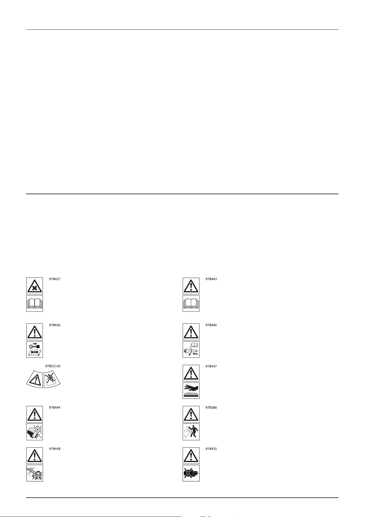
Label explanation
The labels are designating potential dangerous places on the machine. Anybody working with or being in close range of
the sprayer must respect these labels!
The labels should always be clean and readable! Worn or damaged labels must be replaced with new ones. Contact your
local dealer for new labels.
Note that not all labels shown here will apply to your sprayer.
÷
Chemical handling!
Carefully read the informations about
chemical preparation before handling the
machine. Observe instructions and safety
rules when operating.
Service!
Shut off the engine and remove ignition key
before performing maintenance or repair.
Risk of death!
Do not attempt to enter tank.
Service!
Carefully read operators instruction book
before handling the machine. Observe
instructions and safety rules when operating.
Service!
Tighten to torque according to instruction
book.
Risk of burn!
Stay clear of hot surfaces.
12
Risk of injury!
Do not open or remove safety shields while
engine is running.
Risk of injury!
Keep sufficient distance away from electrical
power.
Risk of injury!
Flying objects, keep safe distance from
machine as long as the engine is running.
Risk of injury!
Keep hands away.
Page 13
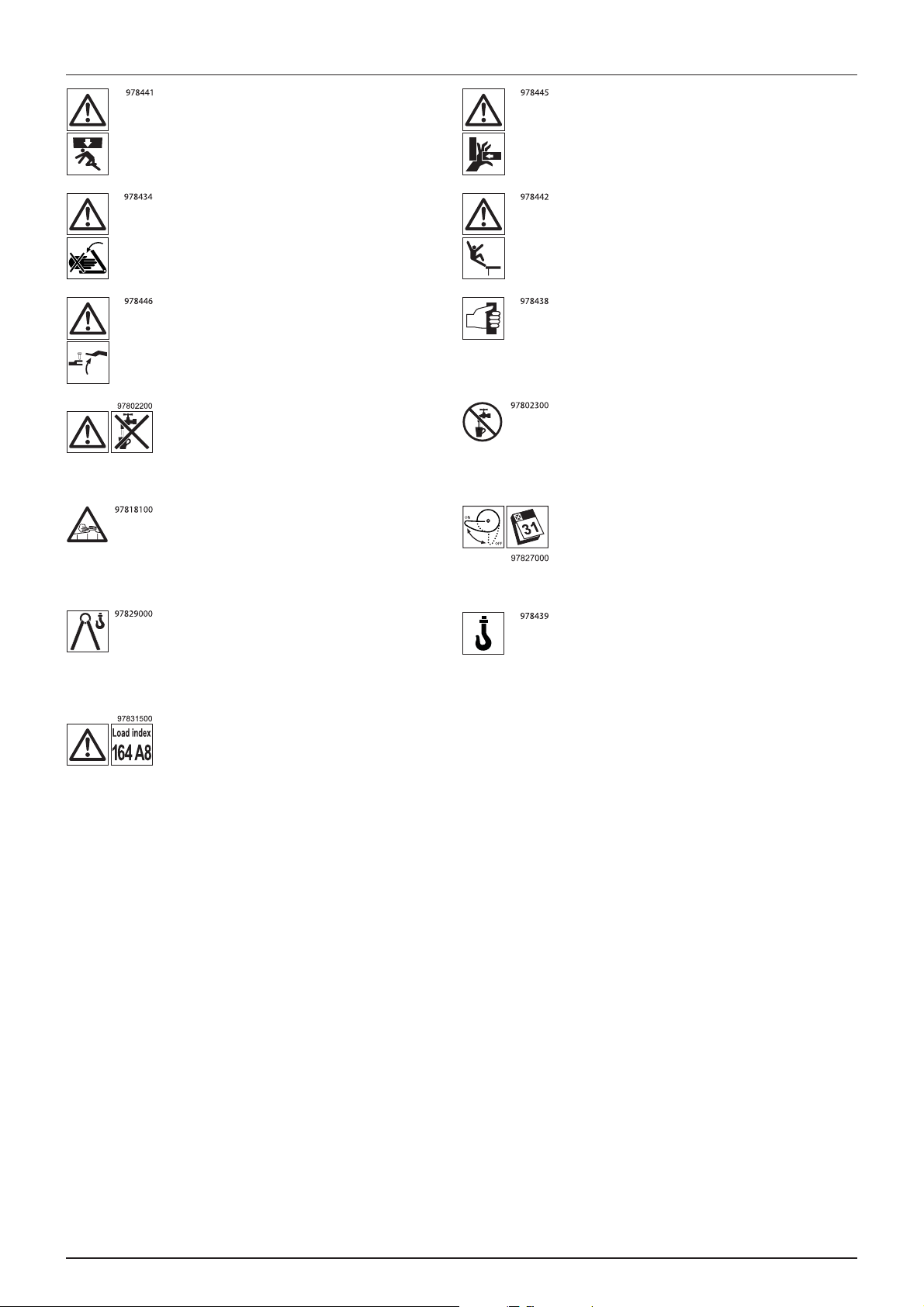
2 - Safety notes
Risk of squeeze!
Stay clear of raised unsecured loads.
Risk of squeeze!
Keep hands away, when parts is moving.
Risk of sprayer tipping over!
Be aware when disconnecting the sprayer.
Not for drinking!
This water must never be used for drinking
water.
Tank u n d e r pressure!
Beware when moving lid.
Risk of squeeze!
Never reach into the crushing danger area as
long as parts are moving.
Risk of falling off!
Do not ride on platform or ladder.
Grapping area!
Manual handling of boom etc.
Not for drinking!
This water must never be used for drinking
water.
EasyClean filter service!
Open and clean filter monthly.
Lifting point! Lifting point!
Load index!
Max. permitted load rating is 164 at 40 km/h.
13
Page 14

2 - Safety notes
14
Page 15
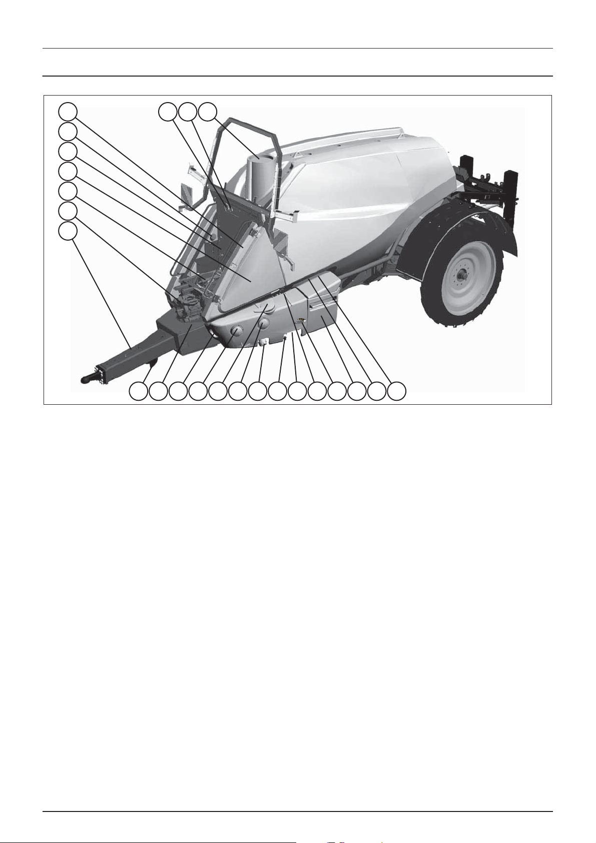
General info
11 10 13 14 15 16 17 18 19 20 21 22 23 24
12
9
8
7
6
4
5 3 2 1
View
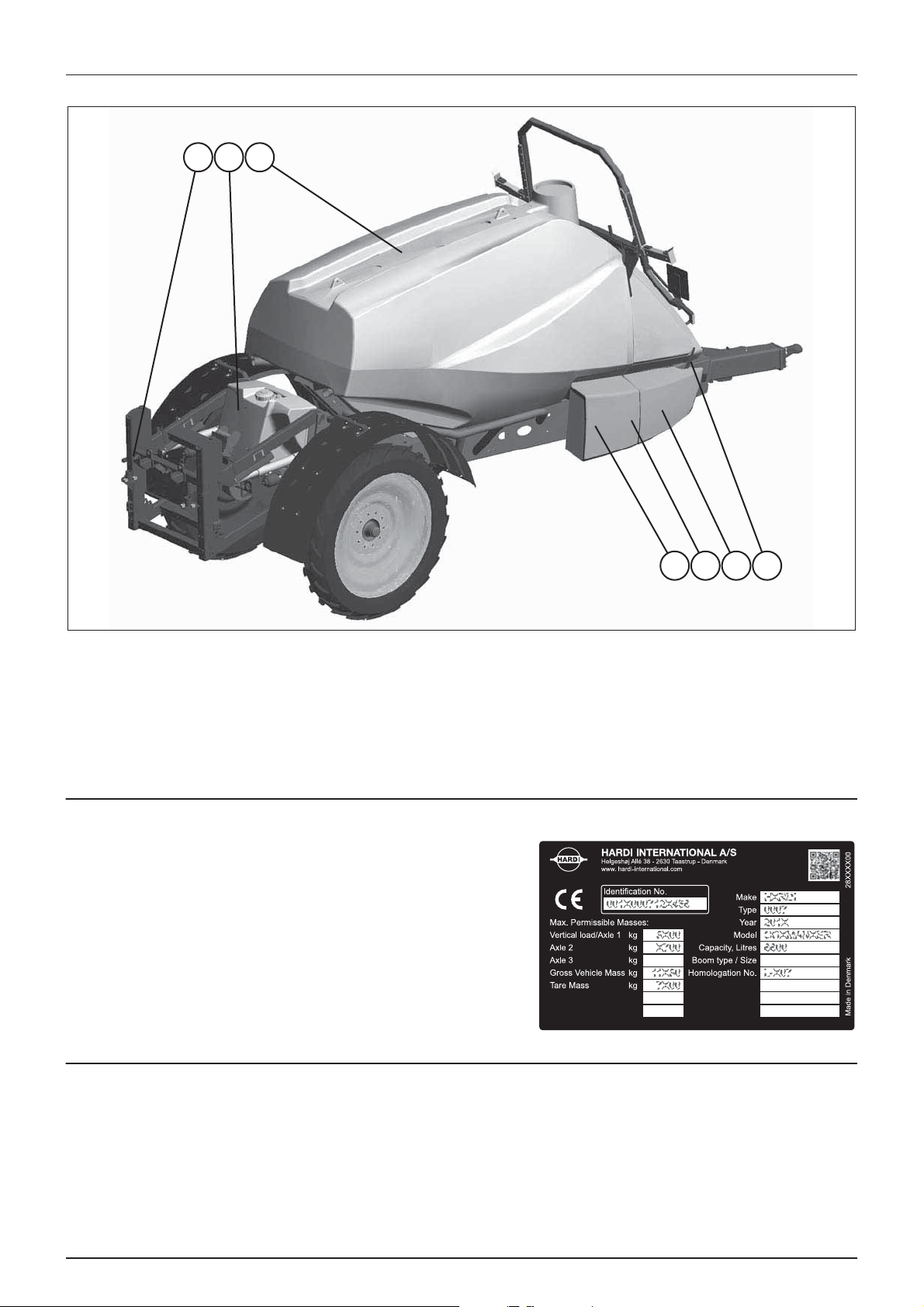
3 - Description
1. Main tank lid
2. EasyClean clogging indicator
3. Spray pressure gauge
4. Clean water tank lid
5. Main tank level indicator
6. Rinsing tank level indicator
7. SafetyLocker
8. Platform
9. Pump
10. Ladder
11. Support leg
12. Drawbar hitch
13. Agitation/External Cleaning Device valve
14. Suction SmartValve
15. EasyClean filter
16. Pressure SmartValve
17. Pressure draining coupler
18. Rinsing tank coupler
19. External Filling coupler
20. Clean water tap
21. External Filling ON/OFF valve
22. TurboFiller
23. Lever for chemical container cleaning
24. TurboFiller Vortex nozzle valve
15
Page 16
3 - Description
25 26 27
28 29 30 31
View
25. Distribution valves (not illustrated)
26. Rinsing tank
27. Main tank
28. ChemLocker with FoamMarker tank
Identification plates
A CE identification plate fitted on the frame indicates producer name,
model, sprayer weights, etc.
The identification plate also has a QR-code which can be read by e.g.
smartphones to obtain more detailed data about the sprayer, which can
be useful for service staff.
Roadworthiness
When driving on public roads and other areas where the highway code applies, or areas with special rules and regulations
for marking and lights on implements, you should observe these and equip implements accordingly.
29. Spray lance for External Cleaning Device
30. CycloneFilter
31. Parking brake
AT TENTION! Max. driving speed for models without brakes and for models equipped with brakes is different. Be aware
that these speeds may differ due to local law. Contact local authorities for information of max. driving speeds!
16
Page 17

3 - Description
Sprayer use
The HARDI sprayer is for the application of crop protection chemicals and liquid fertilisers. The equipment must only be used
for this purpose. It is not allowed to use the sprayer for any other purposes. If no local law demands that the operator must
be certified to use spray equipment, it is strongly recommended to be trained in correct plant protection and in safe
handling of plant protection chemicals to avoid unnecessary risk for persons and the environment when doing your spray
job.
Frame
Very strong and compact frame which also has a strong chemical and weather resistant electrostatic lacquer coat. Screws,
nuts, etc. have been DELTA-MAGNI treated to be resistant to corrosion.
Tanks and equipment
The main tank made of impact-proof, UV-resistant and chemical resistant polyethylene, has a purposeful design with no
sharp corners for easy cleaning. The filling hole is placed so it can be accessed from the platform. This ensures an easy access
for the filling of sprays, cleaning of the tank, etc. The sprayer is also equipped with a rinsing tank and a clean water tank. A
large, easy to read tank contents indicator is placed beside the platform and is visible from the tractor cabin.
Nominal contents 3300, 4500, 5500 or 7000 litres.
17
Page 18
3 - Description
Liquid system
Pump
Diaphragm pump with 6 diaphragms, model 463. Standard = 540 r.p.m. (6 splines shaft). Optional = 1000 r.p.m. (21 splines
shaft). The design of the diaphragm pump is simple, with easily accessible diaphragms and valves which ensures liquid does
not contact the vital parts of the pump.
FlexCapacity pump
Some sprayers facilitates a dual pump setup with an extra hydraulically driven pump of same type as the main pump, placed
on sprayers right side.
The FlexCapacity pump is turned ON/OFF with a separate hydraulic lever in the tractor cabin.
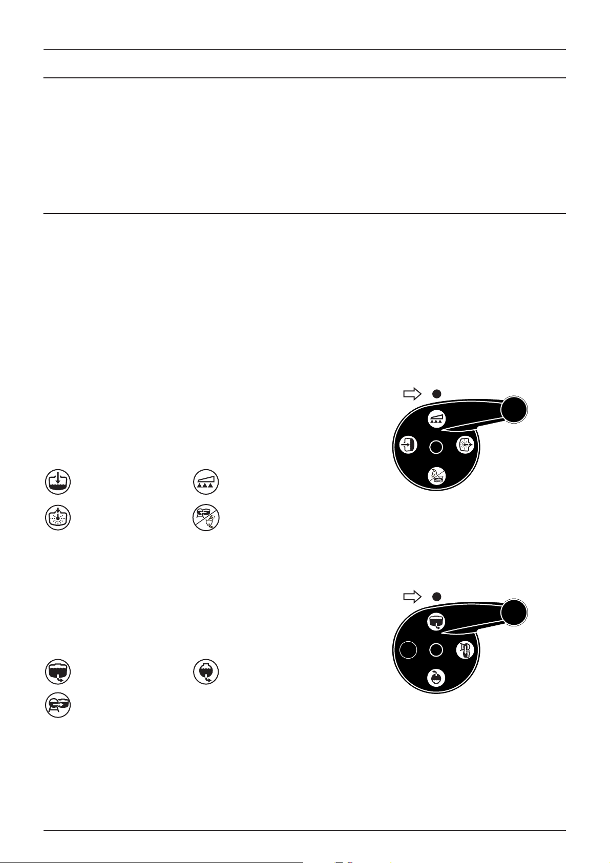
Valves and symbols
The possible functions of valves are distinguished by coloured identification on the function labels. The modular valve
system facilitates the addition of optional extras on both pressure side and suction side. A function is activated by turning
the handle towards the desired function.
ATTENTION! Only the functions used should be open - always close remaining valves.
ATTENTION! If a valve is too tight to operate - or to loose (= liquid leakage) - the valve needs to be serviced. Please see
“Pump valves and diaphragms renewal” on page 93 for further information.
Pressure SmartValve (Green symbols)
This valve is to select which function the pressurized liquid from the
pump will be routed to.
The active function is indicated by the indicator. The handle is turned so
the indicator points to the label for required function. If handle is turned
to a position without label (unused function) then the valve is closed.
Main tank Spraying
Internal tank cleaning
(Rinsing nozzles)
Suction SmartValve (Blue symbols)
This valve is to select suction from main tank or from the rinsing tank.
The handle is turned so the label for required function is directed to the
indicator. If handle is turned to vertical position (indicator not pointing
at a label) then the valve is closed.
Main tank Rinsing tank
Pressure draining (optional)
or TurboFiller
18
External filling (optional)
Page 19

3 - Description
DynamicFluid4 pressure regulation
Traditional fluid regulation starts when the nozzles are opened. With DynamicFluid4 the regulation is a continuous process
that continues even if the nozzles are closed. Two ceramic discs regulates the pressure and ensures quick reaction and zero
leakages. Sprayer speed, P.T.O. RPM and number of sections activated are parameters used, and the benefit is more precise
application rates from the second the sprayer begins spraying.
The DynamicFluid4 use feed forward technology based on 5 sensors that feeds the JobCom computer with data necessary
for optimal regulation. It auto-prime at start-up, starts and move the valve towards the final position immediately after the
operator makes changes. E.g. when section valves are opened or closed, the regulation valve is started at same time as the
section valve motors are started. This avoids overpressure situations e.g. after running empty and refill of main tank.
The 5 sensors are also back-up for each other and ensures the system can continue regulation even if one or more sensor
signal fails. Sensors used are:
• Sprayer speed sensor
• Flow sensor
• Pressure sensor
• Pump r.p.m. sensor
• Regulation valve opening angle sensor
The DynamicFluid4 pressure regulation features are:
• Very fast and accurate regulation when all sensors are ok, setup in menus are correct and pump, filters and valves are
in good conditions.
• Quick reacting valve when sections are turned ON/OFF and at speed changes.
• Optimized AutoSectionControl feature that predict boom sections to open and nozzle pressure.
• Optimized for different P.T.O. systems.
• Nozzle surveillance. No setup or tuning required for nozzle change.
• Warning in display if fail ures o ccur on boom plu mbing, such as seve re cloggi ng of l ine or nozzle f ilter s or large leak age s
on hoses and fittings.
• All functions work though with degraded performance (Limp home modes), if:
Faults occur in fluid system, e.g. pump defects, clogged filters, leaking valves.
Sensor failure appear on pressure sensor, flow sensor or RPM sensor.
There is wrong setup of sprayer data in menus.
• Emergency mode if angle sensor or speed sensor fails.
Screen icons
The sprayer driver selects one of three modes Auto, Manual or Increment steps. The sprayer computer detects one of three
regulation modes Drop, Question mark or calibration jug. This makes 9 modes in total.
Auto Manual Increment steps
When Automatic
Volume Rate button is
pressed on the SetBox.
When one of the
Manual pressure
control buttons is
pressed on the SetBox.
When the Volum e Rate
is changed in steps
with %-up or %-down
buttons on the
Ter mi nal .
Calibration jug
There is flow to section valves.
Nozzle size (L/min at 3 bar) has been calculated.
Drop
There is no flow to section valves.
The pump is not started or the pressure SmartValve is set to other function than spraying.
Question mark
There is flow to section valves but pressure and flow has not yet been stable, therefore
the nozzle size (L/min at 3 bar) has not been calculated.
The system uses the previously stored nozzle size.
19
Page 20
3 - Description
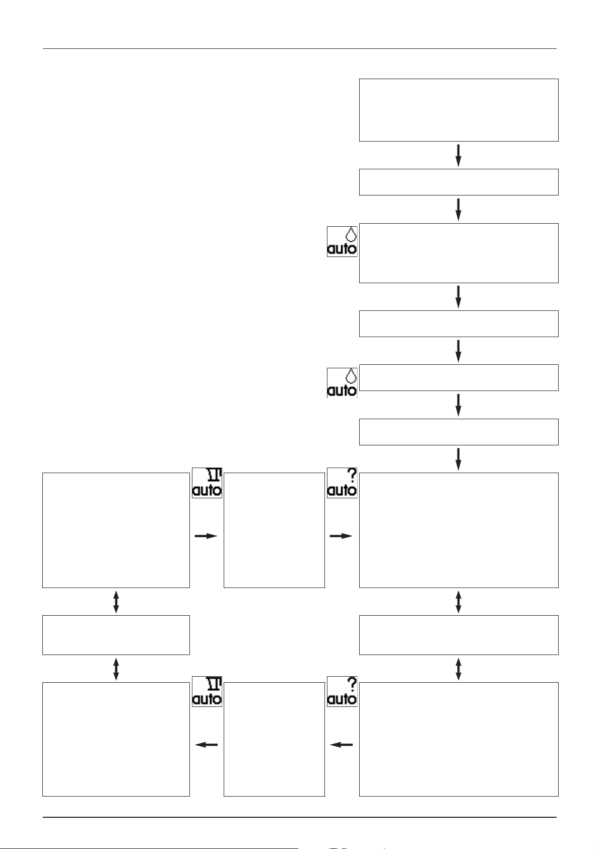
Regulation valve function diagram
ATTENTION! Auto mode icons shown, but could be Manual or
Increment steps icons, depending on driver selection.
Spray job begins
Start condition:
Controller is turned OFF. Pump is turned OFF.
Pressure SmartValve to Pressure draining/TurboFiller, suction
SmartValve to Main tank, have water in Main tank.
Driver action
Turn the controller ON.
Controller reaction
Controller detects no pressure or flow.
Starts in auto mode. Sets regulation valve to safe angle, to
avoid overpressure at pump start and to ensure that software
detects that pump is started (avoid hanging).
Driver action
Turn the pump ON.
Controller reaction
Headland (boom is closed)
Software use nozzle size and feed forward to
prepare for opening of boom.
Max. pressure limit is disabled, because last
saved nozzle size is reliable and therefore
software “dare” to close regulation valve
completely.
Driver action
Turn main OFF at headland. (go up)
Turn main ON to spray. (go down)
Headland (boom is closed)
for over 5 min
Boom is closed for a longer
period, that operator could
have changed to other nozzle
size. Last saved nozzle size
become unreliable.
Software enable max. pressure
limit.
Controller action
Controller detects no pressure or flow, Stay in safe position.
Driver action
Turn pressure SmartValve to Spraying.
Controller reaction
Headland (boom is closed)
Controller detects pressure at armature and bypass flow back
to tank. Software use last saved nozzle size and feed forward
to prepare for opening of boom.
Max. pressure limit is enabled, because last saved nozzle size
is unreliable and therefore software will not close regulation
valve completely. PrimeFlow booms are primed.
Driver action
Turn main OFF at headland. (go up)
Turn main ON to spray. (go down)
Controller reaction
Spraying (boom is open)
Boom is open and sprays.
Both flow measurement and pressure
measurement are good, and the actual
nozzle size is calculated.
The actual nozzle size is used to adjust to
correct liter/ha.
20
Flow and pressure are
good
Both flow measurement and
pressure measurement are
good.
Software disable max. pressure
limit.
Controller reaction
Spraying (boom is open)
Boom is open and sprays.
Software use last saved nozzle size and pressure sensor to
adjust to correct liter/ha.
Max. pressure limit is enabled to avoid overpressure in case
operator had changed to smaller nozzles.
Page 21

3 - Description
Clean water tank
The water in this tank is for hand washing, cleaning of clogged nozzles
etc. Only fill this tank with clean water from the well.
Capacity: approximately 20 litres.
WARNING! Although the clean water tank is only filled with clean
±
water, this water must NOT be used for drinking.
Rinsing tank
A rinsing tank is mounted to the rear of the sprayer. The tank are made of impact-proof and chemical resistant polyethylene.
Filling is done via the 1” threaded stud placed in the working area. The rinsing tank level indicator is placed at the platform.
Nominal content: approximately 450 litres.
Filters
A EasyClean suction filter is fitted in the working zone.
A Cyclone pressure filter is fitted to the sprayers right side just in front of the hose reel, hidden behind the right front cover.
It has a built-in self-cleaning function.
In-line pressure filters can be fitted at each boom section as an option (standard for certain booms).
Nozzle filters are fitted at each nozzle.
All filters should always be in use and their function checked regularly. Pay attention to the correct combination of filter and
mesh size (see “Spray Technique” book).
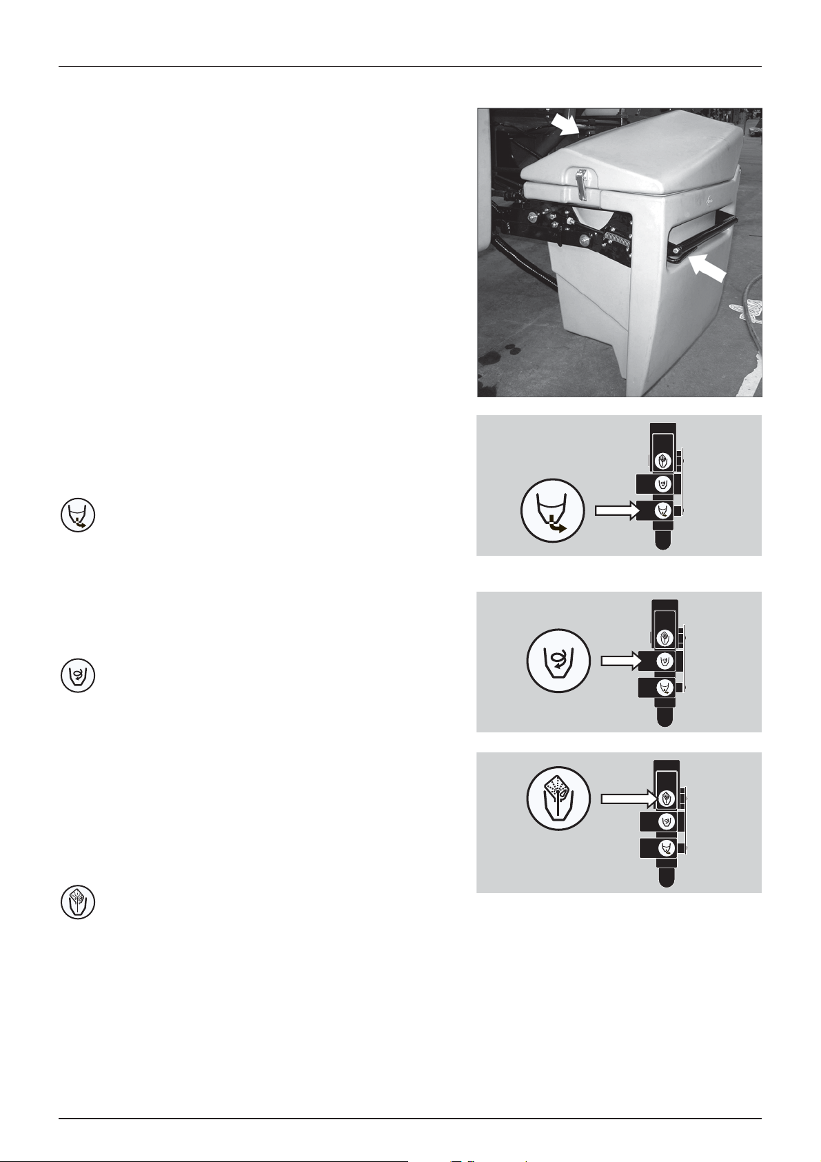
EasyClean filter
To ensure proper function of filter and its built-in valve the filter must be
opened at least 1 time per month. A label on the lid also designates this.
• To open filter then turn it counterclockwise and pull it up, like
shown on picture.
• Pull out the two locks (A) to remove filter element from the lid.
Beside the spray pressure gauge on the platform a EasyClean clogging
indicator is located:
Clogging indicator colour Filter status
Green indicator. No cleaning necessary.
Yellow indicator. It is possible to finish an ongoing spraying job and
Red indicator. Clean EasyClean filter immediately as filter is
then clean filter afterwards.
clogged.
21
Page 22
3 - Description
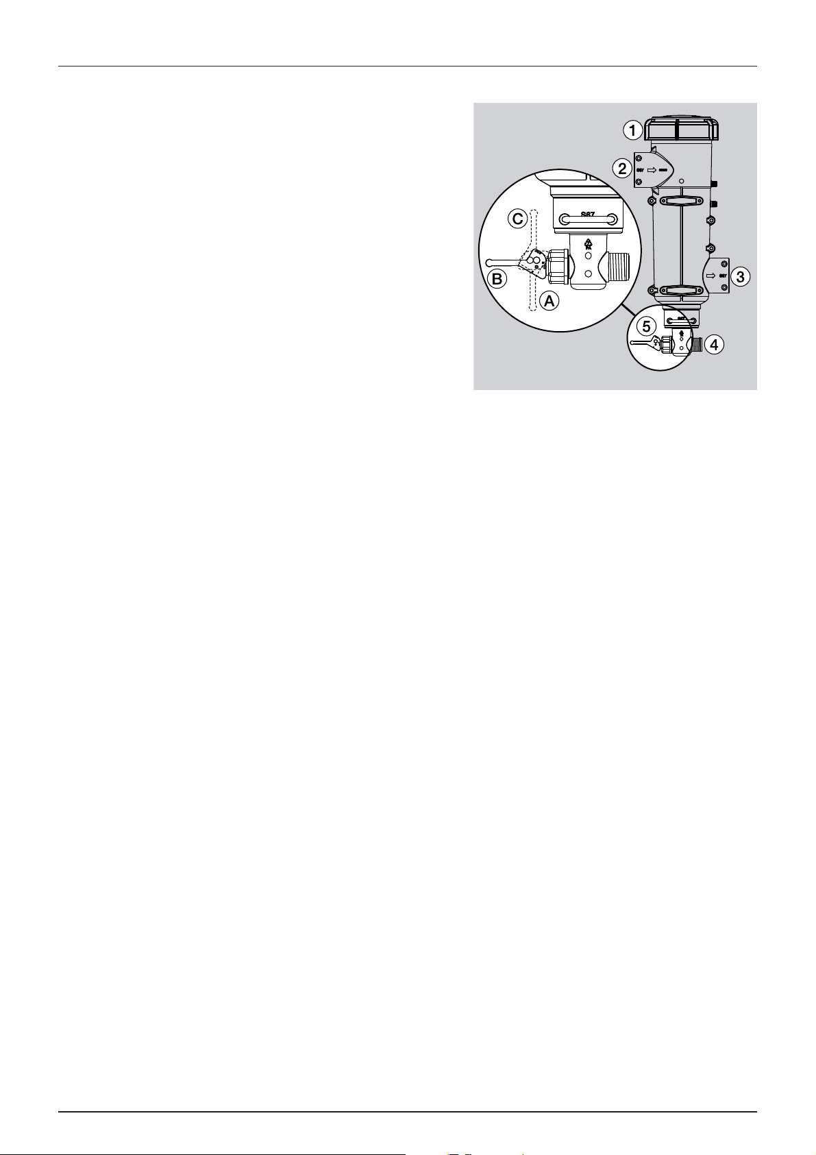
CycloneFilter
With the CycloneFilter any impurities in the spray liquid will by-pass the
filter and be re-circulated back to the tank via the return flow.
Function diagram
1. Filter lid
2. From pump
3. To b o o m
4. Return to tank
5. Return valve
Valve (5) has three positions marked with small dots on the lever:
A. This position marked with 1 dot: There is no return flow. Position is
used when rinsing the boom if there is spray liquid in the main
tank. Also used when high spraying volume is required.
B. This position marked with 2 dots: Normal spraying position. With
return flow to prevent filter is going to be clogged when spraying.
This position is used when rinsing the boom if the main tank is empty.
C. This position marked with 3 dots: Flushing position which is used if filter is clogged. Lift and hold the lever to use this
position which largely increases return flow and flushes the filter. The pressure SmartValve must be set to “Spraying”.
ATTENTION! Use of position C is no guarantee for a clean filter. Always regularly do a visual inspection and cleaning
of the filter. If necessary see “10 hours service - Cyclone Filter” on page 85.
DANGER! Never open the Cyclone filter unless the pressure SmartValve is turned to “Main tank”. Otherwise, spraying
€
liquid may hit you when opening the filter, and drain from the main tank!
22
Page 23
TurboFiller
Before use
• Push the handle (arrow) to unlock.
• Grab the handle to pull TurboFiller down until it clicks into locked
down-position.
After use
• Push the handle (arrow) to unlock.
• Grab the handle to push TurboFiller back in storing position until it
locks.
WARNING! Before releasing the lock (arrowed) always keep a
±
hand on the grip to avoid abrupt movement of the TurboFiller!
The TurboFiller valves and Chemical Container Rinsing lever are placed
on the backside (arrow).
TurboFiller suction valve
The valve is used simultaneously with the TurboFiller. The valve has 2
set tings: C ontin uously o pen or spr ing loaded normally closed. Op en the
valve when chemicals are to be filled into the TurboFiller and transferred
to main tank.
3 - Description
Suction from TurboFiller
TurboDeflector valve
This TurboDeflector valve activates the Vortex flushing of the TurboFiller.
Lift the lever to lock it in open position for continuous liquid rotation in
the hopper.
Start TurboDeflector
Chemical Container Rinsing lever
The upper lever is used for two purposes:
When the TurboFiller lid is open: For rinsing empty containers. Place the
container over the rotating flushing nozzle in the middle of the
TurboFiller to rinse the inside of the container.
When the TurboFiller lid is closed: Use the Chemical Container Rinsing
lever to rinse the hopper when the filling of chemicals is completed.
Chemical Container Rinsing
DANGER! Do not press the lever unless the multi-hole nozzle is covered by a container as spray liquid may otherwise
€
hit the operator.
23
Page 24
3 - Description
9
22
20
23
17
22
10
22
1
2
15
16
22
8
18 19
22
21
7
3
11
14
6
13
22
5 4
28
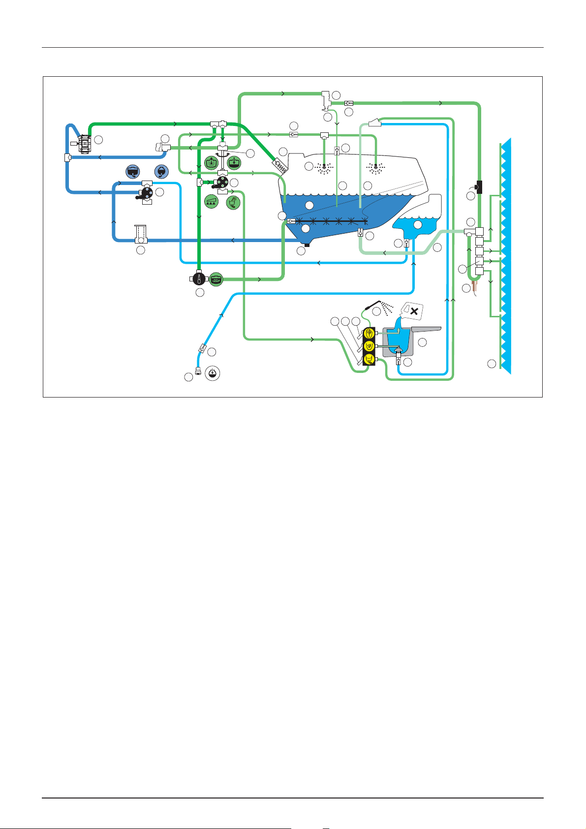
Diagram - Basic liquid system
12
22
37
25
26
22
29
27
1. Suction SmartValve
2. Pressure SmartValve
3. Agitation valve
4. Chemical container cleaning valve
5. TurboDeflector ON/OFF valve
6. TurboFiller suction ON/OFF valve
7. Pump
8. Main tank
9. EasyClean filter
10. RinseTank
11. Spray valve
12. CycloneFilter
13. TurboFiller
14. Lance for cleaning TurboFiller
15. Safety valve
16. Internal tank cleaning nozzles
24
17. Agitation tube
18. Return line for boost function
19. TurboFiller to tank tube
20. RinseTank coupler
21. DynamicFluid4 pressure regulation valve
22. One-way valve
23. Drain valve
24. Sprayer boom
25. Flowmeter
26. Bypass valve
27. Sensor for pressure gauge
28. Distribution valves
29. Return from distribution valves
Options
37. Boost valve
24
Page 25
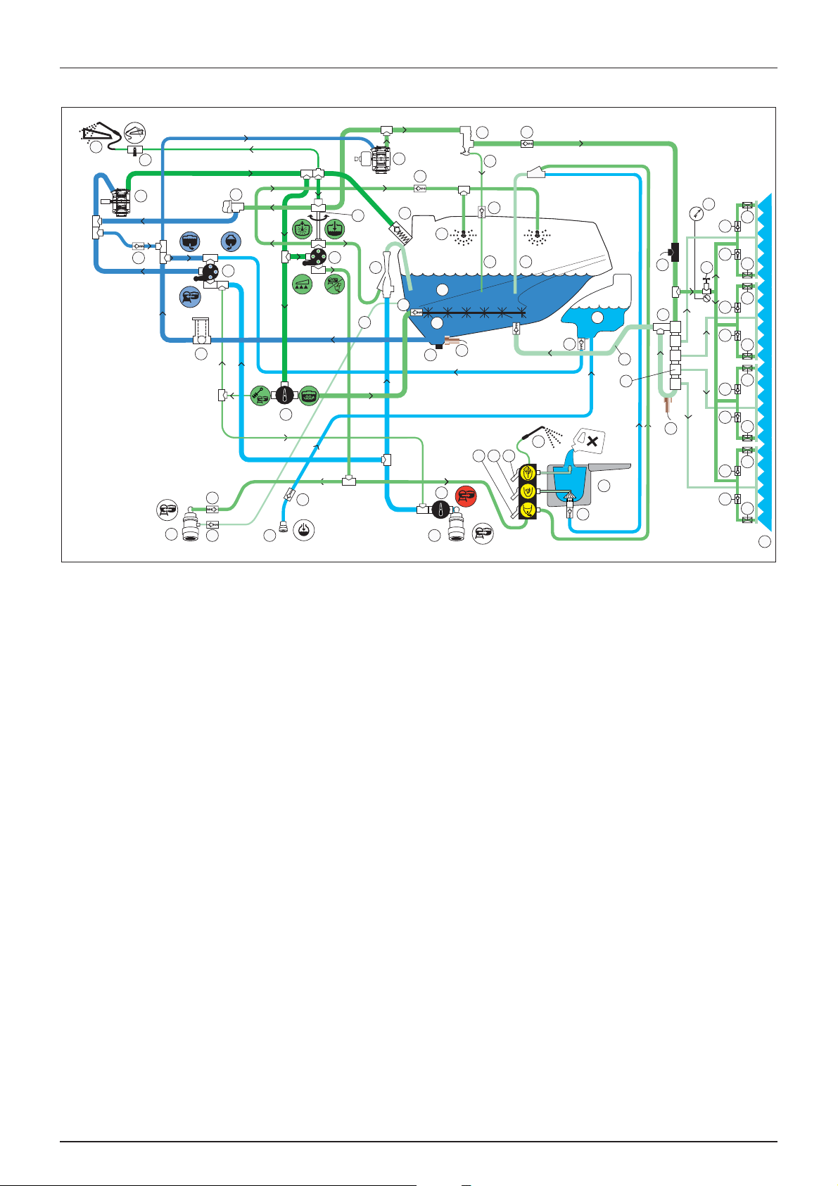
Diagram - Liquid system with optional extras
34
33
32
36
31
22
22
38
41
9
22
20
30
23
17
22
10
22
1
2
15
16
22
8
18 19
22
21
7
3
11
14
6
13
22
5 4
28
3 - Description
12
39
22
22
37
46
40
22
22
25
26
29
27
40
45
40
22
22
39
40
22
22
40
40
22
22
40
1. Suction SmartValve
2. Pressure SmartValve
3. Agitation/External cleaning valve
4. Chemical container cleaning valve
5. TurboDeflector ON/OFF valve
6. TurboFiller suction ON/OFF valve
7. Pump
8. Main tank
9. EasyClean filter
10. RinseTank
11. Spray valve
12. CycloneFilter
13. TurboFiller
14. Lance for cleaning TurboFiller
15. Safety valve
16. Internal tank cleaning nozzles
17. Agitation tube
18. Return line for boost function
19. TurboFiller to tank tube
20. RinseTank coupler
21. DynamicFluid4 pressure regulation valve
22. One-way valve
24
23. Drain valve
24. Sprayer boom
25. Flowmeter
26. Bypass valve
27. Sensor for pressure gauge
28. Distribution valves
29. Return from distribution valves
Options
30. Main tank gauge sensor
31. Pressure draining coupler
32. FastFiller coupler
33. External cleaning device
34. External cleaning ON/OFF valve
36. External fast filling ON/OFF valve
37. Boost valve
38. Ejector
39. FlexCapacity pump
40. Boom prime restrictor
41. Pressure relief line
45. Boom prime pressure control valve
46. Pressure gauge for BoomPrime
25
Page 26
3 - Description
42
43
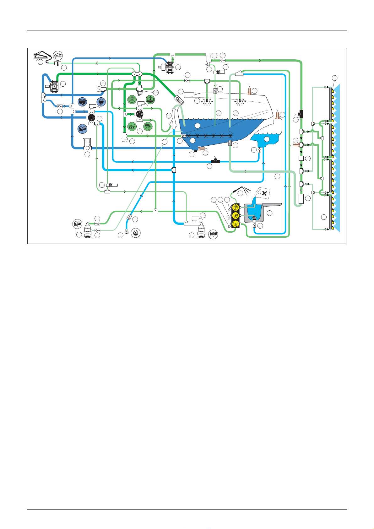
Diagram - Intelligent liquid system with optional extras
33
34
7
21
11
39
22
15
22
12
40
37
36
22
16
45
22
1
9
22
31
22 20
1. Suction SmartValve
2. Pressure SmartValve
4. Chemical container cleaning valve
5. TurboDeflector ON/OFF valve
44
30
18 19
6
5 4
22
22
14
22
38
2
35
22
22
41
8
17
23
32
47
25
10
13
27
26
29
26
24
25. Flowmeter
26. Distribution valves
27. Sensor for pressure gauge
29. Return from distribution valves
6. TurboFiller suction ON/OFF valve
7. Pump
8. Main tank
9. EasyClean filter
10. RinseTank
11. Spray valve
12. CycloneFilter
13. TurboFiller
14. Lance for cleaning TurboFiller
15. Safety valve
16. Internal tank cleaning nozzles
17. Agitation tube
18. Return line for boost function
19. TurboFiller to tank tube
20. RinseTank coupler
21. DynamicFluid4 pressure regulation valve
22. One-way valve
23. Drain valve
Options
30. Main tank gauge sensor
31. Pressure draining coupler
32. FastFiller coupler
33. External cleaning device
34. External cleaning ON/OFF valve
35. AutoAgitation valve
36. PrimeFlow ON/OFF valve
37. Boost valve
38. Ejector
39. FlexCapacity pump
40. Boost line valve ON/OFF
41. Pressure relief line
42. Clean valve
43. RinseTank flowmeter
44. External fast filling ON/OFF valve
45. Main tank full sensor
47. RinseTank full sensor
24. Sprayer boom
26
Page 27

3 - Description
TWIN Air technique
General info
With TWIN air assistance energy is added to the spray droplets to
improve control with the spray liquid. The main purpose of the TWIN
angling system is to counteract for the negative influence which wind
direction and driving speed have on the quality of the spray job. Further
the “co-angling” af air and liquid can help “opening” dense crops for
better penetration.
This way TWIN makes it possible to:
• carry the spray droplets safely to the target and increase plant
deposit.
• minimize off-target deposit due to wind drift or loss on the ground.
• open the crop and obtain good penetration even with a low
volume rate.
• ensure a high coverage.
The TWIN FORCE air system can be set at any angle from 40° forward to 30° back (defined by the air stream). The fan speed
is infinitely variable and can produce from 0 to 35 m/s (78 mph) air speed at the air outlet. This equals from 0 to 2000 m3
air/m boom/hour (3.872 CFM/A boom/hour).
27
Page 28

3 - Description
Boom
Boom and terminology
The TWIN FORCE boom are found in two hydraulic versions which is suspended in a strong, stable parallelogram boom lift:
• HAY boom:
Working widths are 18, 20, 21, 24, 27, 28 and 30 metres.
The boom is pendulum suspended and equipped with 4 hydraulic rams. The raising/lowering and folding/unfolding
functions are operated via the tractor hydraulics.
• HAZ boom:
Working widths are 18, 20, 21, 24, 27, 28, 30, 32, 33 and 36 metres.
The boom is pendulum suspended and fully hydraulically operated, all functions are controlled via the Direct Acting
Hydraulic System (D.A.H.). The 32-36 metres booms is fully hydraulically operated, all functions are controlled via the
Direct Hydraulic System (D.H.).
Boom features
• All booms are 2-folded.
• TWIN blowers. These are driven by a built-in hydrostatic transmission powered via the tractor P.T.O. Blower speed can
be adjusted step wise from the tractor cabin.
• Outer sections incorporate spring-loaded breakaway.
• Hydraulic pendulum lock (HAZ only).
• Individual boom tilt control (HAZ only).
• Individual folding of outer sections. This enables alternative boom widths.
The boom can be used in half folded position. Half folded lengths are the following:
Full working width 1/2 folded
18 metres 12 metres
20 metres 12 metres
21 metres 12 metres
24 metres 12 metres
27 metres 14 metres
28 metres 14 metres
30 metres 15 metres
32 metres 17 metres
33 metres 17 metres
36 metres 18 metres
For 2-folded booms the terminology are as follows:
A. Breakaway section
C. 1st outer wing
E. Inner wing
F. Centre section
28
Page 29
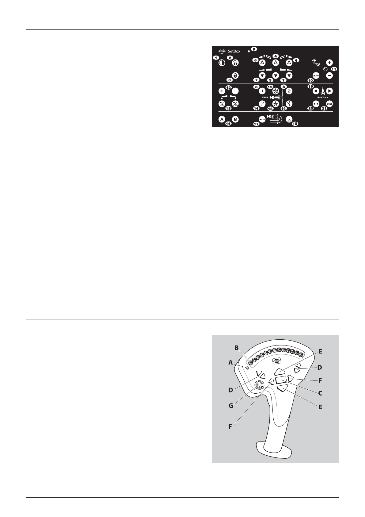
SetBox controls
The SetBox controls the volume rate, foam marker, SafeTrack,
HeadlandAssist, pendulum lock, boom folding and stability functions.
Furthermore two optional functions can be controlled. The buttons on
the SetBox control the following functions:
1. Power ON/OFF.
2. Pendulum unlock.
3. Pendulum lock.
4. Inner wing fold.
5. Inner wing unfold.
6. 1st outer wing fold.
7. 1st outer wing unfold.
8. TWIN presets.
9. Power/status LED.
10. Automatic volume rate selector.
11. Manual pressure control.
3 - Description
12. Foam marker regulation.
13. Foam marker Left/Right selector.
14. TWIN air slot angle.
15. TWIN air volume.
16. Optional function A-B.
17. HeadlandAssist automatic.
18. HeadlandAssist boom align.
19. SafeTrack manual control.
20. SafeTrack align selector.
21. SafeTrack automatic selector.
Grip controls
The grip controls the following:
A. Status LED.
B. Boom section controls.
C. Main ON/OFF.
D. Tilt.
E. Boom height.
F. Boom slant.
G. Option selection switch.
29
Page 30
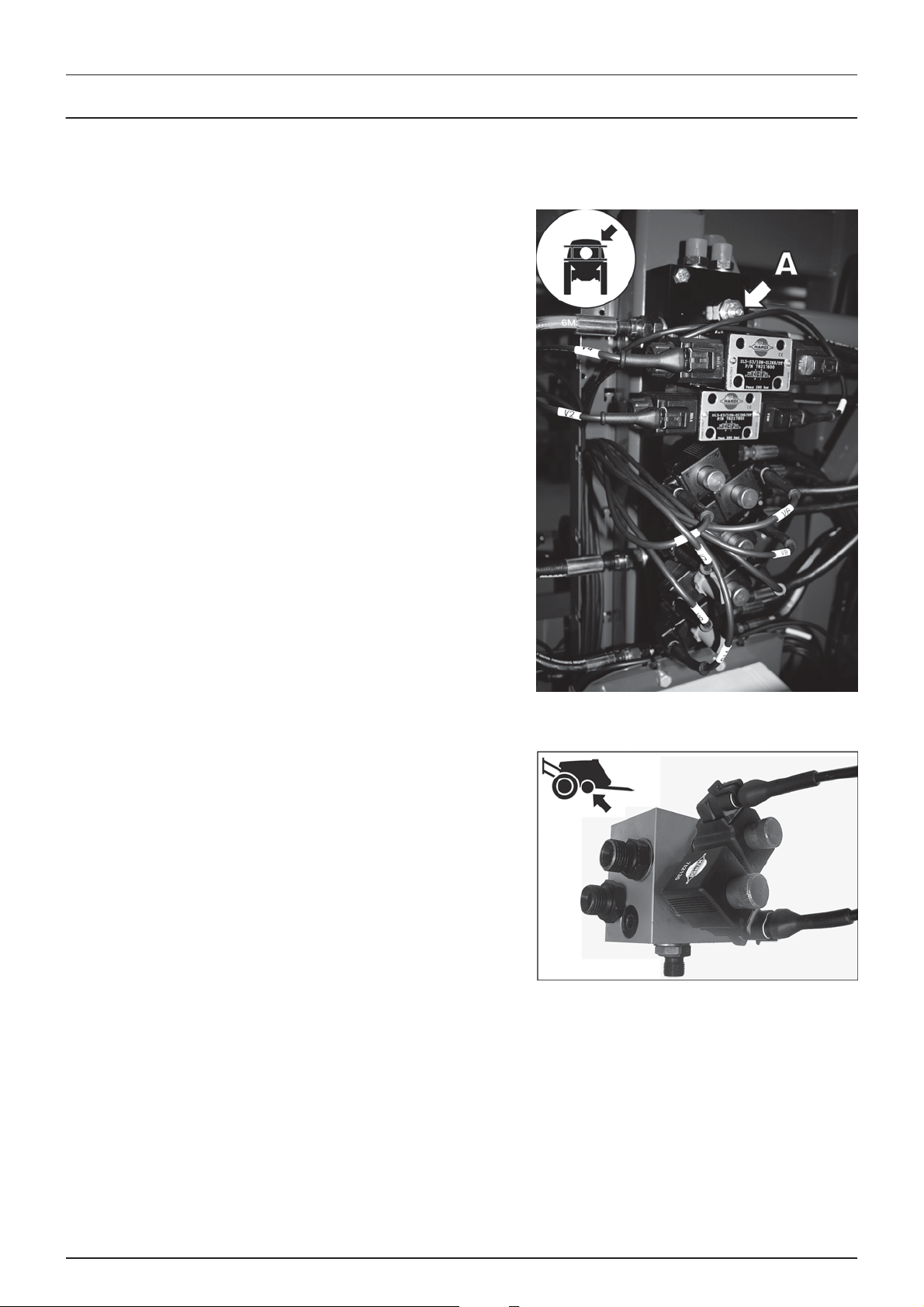
3 - Description
Hydraulic systems
Hydraulic blocks
Hydraulic blocks fitted to the sprayer are:
Boom
The main boom hydraulic block that manages hydraulic pressure for the
boom controls.
The throttle valve (A) can adjust the folding speed of the boom.
Adjusting inwards = slower boom.
ParaLift
This hydraulic block manages hydraulic pressure for the ParaLift.
30
Page 31

Open centre hydraulics
The open centre hydraulics block is necessary if the tractor uses open
centre hydraulics and/or load sensing. For adjustment see “Open centre
hydraulics (optional)” on page 44.
SafeTrack
On sprayers with SafeTrack steering this hydraulic block manages
hydraulic pressure for the steering functions.
3 - Description
AutoHeight UC5
On sprayers with AutoHeight this hydraulic block manages hydraulic
pressure for the automatic boom height control functions.
31
Page 32

3 - Description
Equipment
SafeTrack
The SafeTrack will make the sprayer automatically follow the tractor when turning on headland. The SafeTrack can easily be
operated with the hydraulic control unit. SafeTrack has an integrated safety feature which prevents over-steering when the
driving speed is too high for the given turning radius. If a TankGauge is fitted, the tank filling level is also taken into account.
The SafeTrack is limited to speeds below 30 km/t. Driving in “Auto” with SafeTrack will trigger an overspeed alarm and sprayer
will automatically align.
WARNING! During road transport the drawbar must be aligned in centre position. Refer to the HC 6500/9500
±
controller instruction book for specific instructions.
NOTE! IntelliTrack requires the HC 6500/9500 or ISOBUS controller. More information about the controller can be
÷
found in the separate instruction book.
Driving technique for SafeTrack
A trailer with SafeTrack behaves differently than a normal trailer. In
tracking position the vehicle centre of gravity is displaced more outward
compared to the vehicle centre line of a normal trailer. Compared to a
conventional trailer a steered trailer has decreased stability when
turning, especially when turning on hillsides (B).
To avoid overbalancing, pay attention to these guidelines:
• Avoid sudden, tight turns.
• Slow down before entering a curve or turning, and drive with a
constant, low speed during the turn.
• Never slow down too fast, never brake heavily and never stop
suddenly in a curve, or when turning on a hillside, when the
sprayer is articulated.
• Be careful when turning on uneven ground.
• Set the track width (A) as wide as possible.
• The proper function of the hydraulic system is essential to obtain
good stability.
• A filled rinsing tank will increase stability.
DANGER! No persons are allowed in the operations area of the sprayer when steering is unlocked!
€
WARNING! Never articulate steering when boom is in transport position.
±
32
Page 33
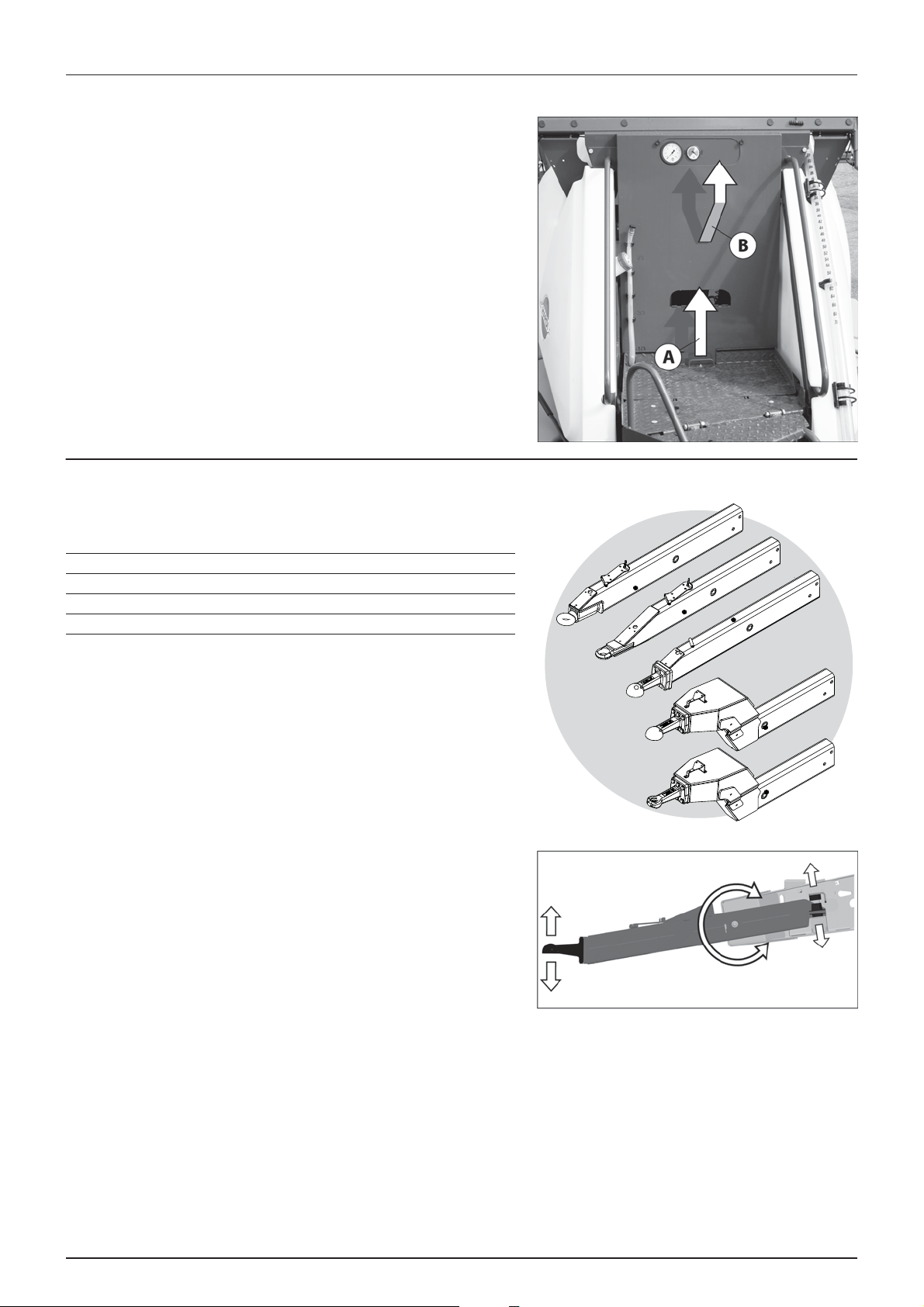
Platform
To get access to the platform pull and tilt the ladder down. In retracted
position the ladder is secured by a rubber stop.
From the platform following can be accessed:
• Main Tank lid.
• Clean water tank lid, integrated to the side of the platform.
• Lift and remove the platform floor (A) to get access to hydraulic
and MANIFOLD components underneath the platform floor.
• Electronics and optional fast filler are situated behind the cover (B).
• Pressure gauge, EasyClean filter clogging indicator and level
indicator for the rinsing tank are visible here.
ATTENTION! Always tilt up the ladder before driving.
Drawbars
3 - Description
Following drawbar systems are available:
Drawbar Hitch type Hitch attachment High/low
A Swivel Ø50/33 Welded Low
B* Hitch Ø50 Welded Low
C Scharmüller Kugel K80 Bolted on Low
D* Scharmüller Kugel K80 Bolted on High
E* Zugmaul Ø40 high Bolted on High
*not for COMMANDER 5500 and 7000 models.
Suspended drawbar
For COMMANDER 5500 and 7000 models the drawbar is fully suspended.
The full up and down load from the sprayer to the tractor are transferred
through rubber dampers built into the chassis.
A
B
C
D
E
33
Page 34

3 - Description
Hydraulic support leg
The hydraulic support legs are driven by a separate hydraulic outlet on the tractor. See “Hydraulic support leg (option for CM
3300/4500)” on page 40 for use of the support leg.
DANGER! Do never leave the sprayer standing unlocked on the support leg. Always double check that the lever is in
€
locked position.
Optional for CM 3300/4500
The support leg is stored in its retracted position when the sprayer is
attached to the tractor.
Pull the knob (A) to fold-up the support leg to its storing position.
Standard for CM 5500/7000
The support leg is stored in its retracted position when the sprayer is
attached to the tractor.
34
Page 35

Tank level indicator
The actual tank level in the main tank can be observed on the tank level
indicator. The scale is displayed in litres or Imp. gal/US gal. (certain
countries).
ATTENTION! The wire guide wheels should be directed so they
follow the direction of the wire.
External Cleaning Device (optional)
3 - Description
This equipment comprises a hose reel and spray gun (C) used to clean
the complete sprayer externally in the field with clean water. The
External Cleaning Device gun (C) is located on the sprayers right side
behind the ChemLocker cover.
Ball valve:
A. Open
B. Closed
NOTE! Do not let go of the hose. Gently restrict the roll-in of the
÷
hose.
WARNING! The Cleaning Device produces a high pressure and
±
incorrect use may result in personal injuries!
DANGER! Never work in bare feet or sandals. It is recommended
€
to wear goggles during the work. It is recommended that the user
or anyone near the cleaning place protects himself against particles bouncing up during the cleaning.
DANGER! For the safety of yourself and others, the following rules should always be observed:
€
Never point the water jet at people, animals, electrical installations or other sensitive objects.
Never try to clean clothing or footwear which you or other people wear.
Nozzle pressure gauge
The remote pressure gauge is integrated at the top of the platform. This
gauge measures the working pressure in the boom tubes as close to the
nozzles as possible.
The outputs stated in the nozzle charts are always based on the pressure
measured at the nozzle. Both when calibrating and spraying, the
pressure must be adjusted according to the readings of this pressure
gauge.
35
Page 36

3 - Description
SafetyLocker
The locker is integrated to the front just above the SmartValves. It is for
the purpose of storing non-contaminated protective gear, soap for hand
washing etc.
The locker is split in two compartments for the separation of clean
clothes from gloves with risk of contamination and facilitates a soap
dispenser (A).
WARNING! Although this locker is meant for storing nontoxic
±
items, it must never be used for storing food, beverage or other
things meant for consumption.
ChemLocker
A ChemLocker for storage of chemical containers etc. is mounted on the
sprayers right side.
If the optional FoamMarker are selected then the FoamMarker tank are
placed into the ChemLocker.
ATTENTION! Max. load 100 Kg./100 litre.
The ChemLocker has a drain-able plastic insert.
36
Page 37

3 - Description
Night Spraying Light (optional)
The 2 boom floodlight lamps (A) are mounted to the booms (one at
each side) and are positioned to illuminate both boom wings. Booms
from 28 metres and up do have another two floodlights mounted in
order to further illuminate the outer ends of the boom.
The work light lamp (B) is also mounted to the railing of the platform
above the valves. This lamp is positioned to lighten the HARDI
TurboFiller and the valve system. The boom and work lights selector
switch is placed just below the SafetyLocker (between valve shield and
EasyClean filter).
ATTENTION! It is recommended to switch OFF the rear working
lights of the tractor in order to save power consumption and to
avoid reflection. Power supply is via the 2-pin socket. Please see the Installation Instruction in the part Technical
specifications.
ATTENTION! Turn OFF all the work lights when driving on public roads!
37
Page 38

3 - Description
38
Page 39
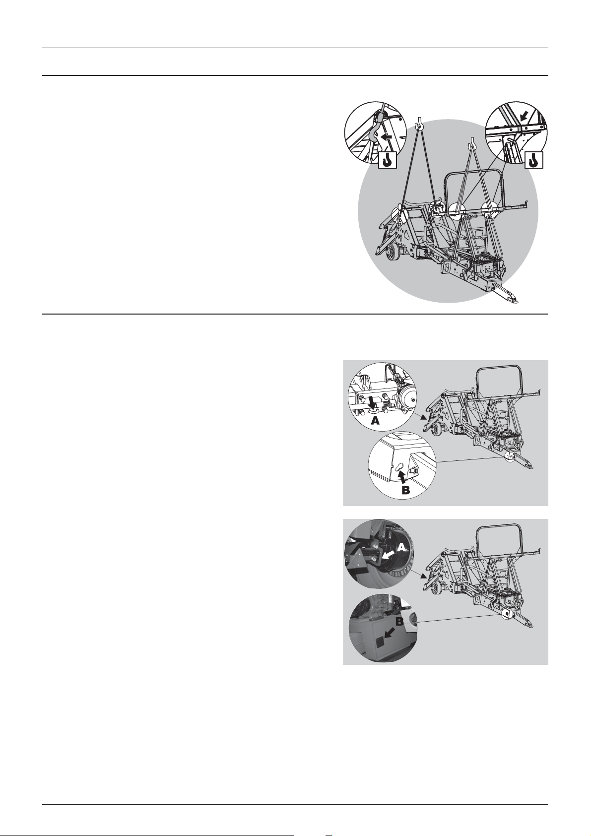
General info
Unloading the sprayer from the truck
For the unloading of the sprayer, you need a crane. When unloading
with a crane please observe the lifting points as shown in the picture,
and make sure that the straps or belts used for lifting are strong enough.
ATTENTION! Only lift the sprayer when the tanks are empty!
4 - Sprayer setup
Pulling the sprayer at the tie down hooks
For moving the sprayer or loading it to e.g. a truck it can be pulled in the hooks at the rear-end (A) and front-end (B) as shown.
COMMANDER 3300/4500
COMMANDER 5500/7000
Before putting the sprayer into operation
Although the sprayer has been supplied with a strong and protective surface treatment on steel parts, bolts etc. in the
factory, it is recommended to apply a film of anticorrosion oil (e.g. CASTROL RUSTILO or SHELL ENSIS FLUID) on all metal parts
in order to avoid chemicals and fertilizers discolouring the enamel.
If this is done before the sprayer is put into operation for the first time, it will always be easy to clean the sprayer and keep
the enamel clean for many years. This treatment should be carried out every time the protection film is washed off.
39
Page 40
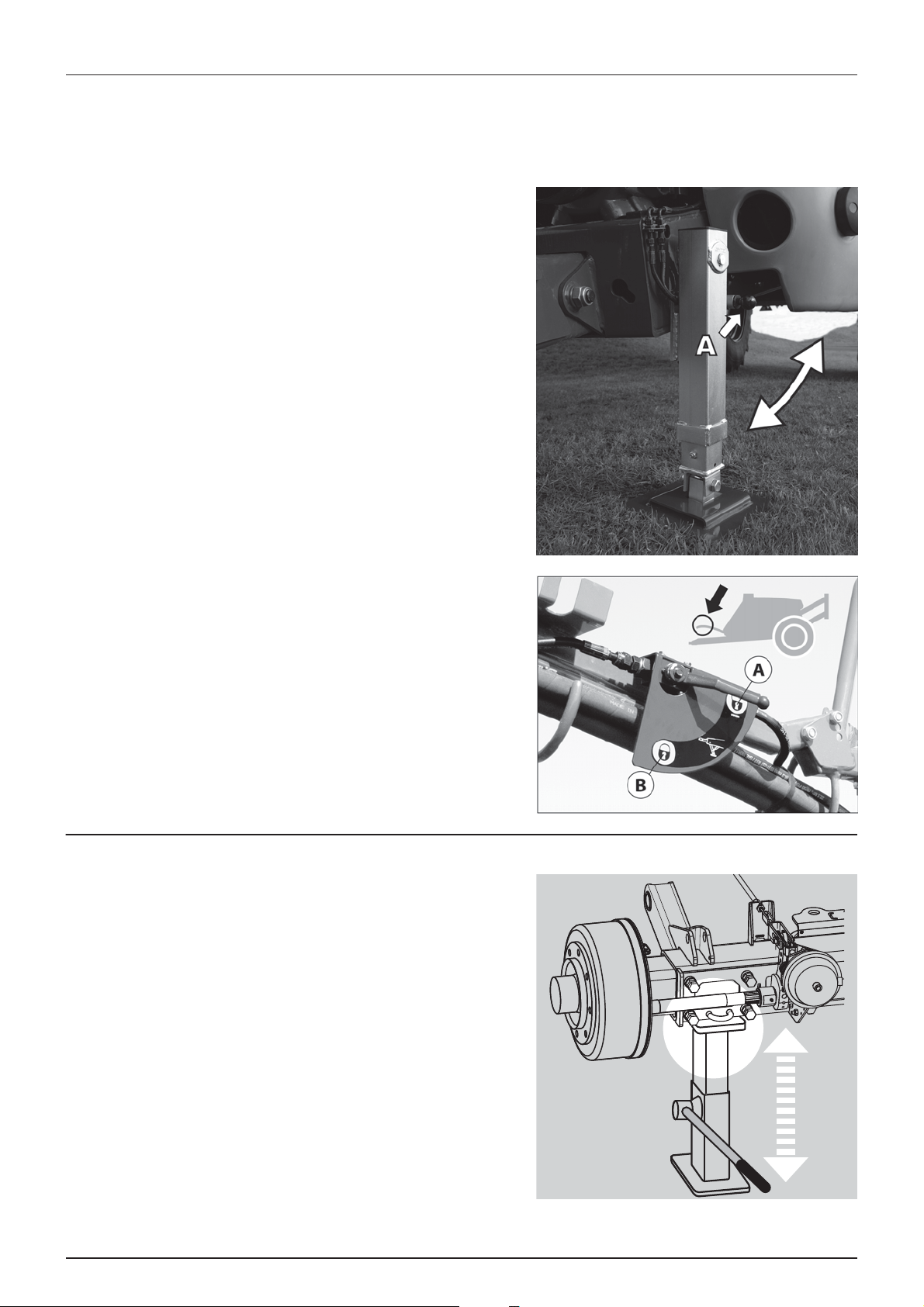
4 - Sprayer setup
Hydraulic support leg (option for CM 3300/4500)
The hydraulic support leg is driven by a separate double acting hydraulic outlet on the tractor. The support leg is stored in
its retracted position when the sprayer is attached to the tractor.
To raise/lower the support legs
1. Pull the knob (A) to fold-up/down the support leg to/from its
storing position.
NOTE! This does not apply to the CM 5500/7000 support leg.
÷
2. Unlock the leg by turning the securing grip to position (A).
3. Use the tractor’s hydraulic lever to raise or lower the support leg.
4. Secure the leg by turning the grip to position (B).
DANGER! Do never leave the sprayer standing unlocked on the
€
support leg. Always double check that the lever is in position (B).
Jack up the sprayer
When the sprayer needs wheel mounting, wheel changing, brake or
wheel bearing changing etc. then jack up the sprayer under the axle as
shown.
DANGER! Be sure to place sprayer at level and firm ground to
€
avoid sprayer falling down from the jack.
ATTENTION! It is good practice to use stop wedges at the
opposite wheel!
40
Page 41
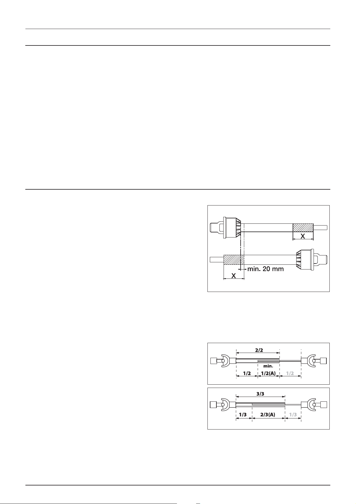
4 - Sprayer setup
Transmission shaft
Operator safety
1. Always STOP THE ENGINE before attaching the transmission shaft to the tractor P.T.O. - most tractor P.T.O. shafts can be
rotated by hand to facilitate spline alignment, when the engine is stopped.
2. When attaching the shaft, make sure that the snap lock is FULLY ENGAGED - push and pull the shaft until it locks.
3. Always keep protection guards and chains intact and make sure that it covers all rotating parts, including CV-joints at
each end of the shaft. Do not use without protection guard.
4. Do not touch or stand on the transmission shaft when it is rotating - safety distance: 1.5 meter. Also NEVER cross over
a rotating P.T.O. shaft to reach the other side of the sprayer.
5. Prevent protection guards from rotating by attaching the chains allowing sufficient slack for turns.
6. Make sure that protection guards around the tractor P.T.O. and the implement shaft are intact.
7. Always STOP THE ENGINE and remove the ignition key before carrying out maintenance or repairs to the transmission
shaft or implement.
DANGER! ROTATING TRANSMISSION SHAFTS WITHOUT PROTECTION GUARDS ARE FATAL.
€
P. T. O. i ns t a l la t i o n
Always read the manufacturer’s instruction book before applying any
installation of the transmission shaft!
First installation of the transmission shaft is done in the following way:
1. Attach the sprayer to the tractor and set the sprayer height in the
position with the shortest distance between the tractor and the
sprayer pump P.T.O. shafts.
2. Stop the engine and remove the ignition key.
3. If the transmission shaft needs to be shortened, pull the shaft
apart. Fit the two shaft parts to the tractor and the sprayer pump
and measure how much the shaft needs to be shortened. Also
mark the protection guards with the same length to be shortened.
WARNING! Do only shorten the shaft if absolutely necessary!
±
WARNING! The shaft must always have minimum overlap of half a shaft length!
±
The recommended overlap (A) of the two shaft parts is 2/3 of the length.
The shaft must always have minimum overlap (A) of 1/2 of the length.
DANGER! As P.T.O. shafts are dangerous, always read the
€
manufacturer’s instruction book before applying any changes to
the transmission shaft!
41
Page 42

4 - Sprayer setup
Mechanical connections
Hose package support
To prevent hoses and wiring from being damaged by the tractor wheels,
P.T.O. shaft etc. all hoses, cables and wires are held by the hose package
support fitted to the sprayer platform.
The bracket (A) is for the storing of hydraulic and electric connectors etc.
when the sprayer is disconnected from the tractor. The height of the
bracket can be adjusted by the means of the bolts (B).
ATTENTION! Check that the length of the hoses and cables are
sufficient by tight turns.
ATTENTION! A sprayer with SafeTrack requires more slack in the cables. Make sure cables are long enough in tight
turns when fully steered.
SafeTrack potentiometer connection
When connecting the SafeTrack sprayer to the tractor it is important to
set up the front potentiometer on the drawbar correctly. The
potentiometer must be connected to the tractor with the supplied 2
chains.
NOTE! To ensure a high precision the chains must be parallel and
÷
horizontal.
NOTE! To ensure a high precision the tractor hitch point may not
÷
have any sidewards movement.
Procedure when connecting the sprayer to the tractor:
1. Connect the sprayer.
2. Drive forward to ensure the sprayer follows the tractor in a straight line.
3. Connect the two chains for the potentiometer, while ensuring the transverse potentiometer bar is perpendicular to
the drawbar. The chains must be parallel and horizontal, and tightened so that the torsion levers (A) are vertical.
4. Check if the potentiometer is reading 2.50 Volt, i.e. in centre position. Go to:
HC 6500 / ISOBUS VT: Menu 4.5.4.6 Track sensor test and check if the Front sensor reading is 2.50 Volt.
5. If the voltage reading is not correct, then adjust the chain connection until voltage = 2.50 Volt. Allowable deviation is
±0.05 Volt.
42
Page 43

4 - Sprayer setup
Hydraulic systems
General info
Ensure that the snap couplers are clean before connection!
After having operated the boom and the system has been filled with oil, check the tractor’s hydraulic oil level and top up, if
necessary.
DANGER! Test of the hydraulic system should be done very cautiously. There may be air trapped in the system which
€
can cause violent movements of the boom.
DANGER! Hydraulic leaks: Never use your fingers to locate a leakage in any part of the hydraulic system. Due to high
€
pressure, hydraulic oil may penetrate the skin.
Requirements - tractor (HAY model)
Connection requirements are:
• A single outlet to raise or lower the boom.
• A double outlet to fold or unfold the boom.
• A double outlet for Hydraulic Slanting Control (optional equipment).
ATTENTION! The hydraulic hoses are marked with arrows to indicate direction of oil flow.
• Oil flow between 25 and 130 l/min and a min. pressure of 160 bar.
• Maximum permissible oil pressure is 210 bar.
• Return flow restriction of the connected tractor must be maximum 15 bar.
• For Load Sensing systems an oil flow of approximately 3 l/min at 25 bar supplied by the sprayer hydraulics.
Requirements - tractor (HAZ model)
The hydraulic system requires:
• One double-acting outlet for the electro-hydraulic operation of the boom functions.
• One double-acting outlet for the operation of the FlexCapacity pump (optional).
• One double-acting outlet for the operation of the hydraulic support leg.
ATTENTION! The hydraulic hoses are marked with arrows to indicate the direction of oil flow.
• Oil flow between 25 and 90 l/min and a min. pressure of 170 bar.
• Maximum permissible oil pressure is 210 bar.
• Return flow restriction of the connected tractor must be maximum 15 bar.
• For Load Sensing systems an oil flow of approximately 3 l/min at 25 bar supplied by the sprayer hydraulics.
43
Page 44
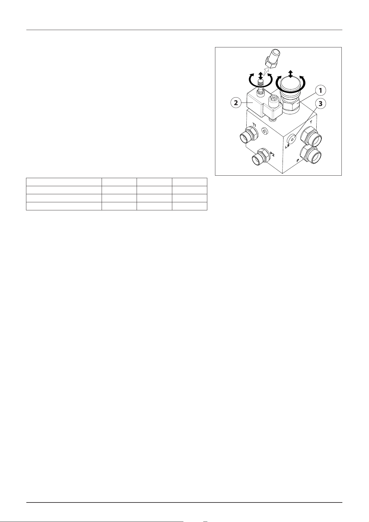
4 - Sprayer setup
Open centre hydraulics (optional)
The open centre hydraulics block is necessary if the tractor uses open
centre hydraulics and/or load sensing.
The valves (1) and (2) is factory set for open centre hydraulics, but if
closed centre hydraulics is used (also in combination with load sensing),
screw in the valve (clockwise).
Certain tractor models are able to use Load Sensing without connecting
an external sensing line. But if optimal sensing control pressure cannot
be obtained, an external sensing line needs to be connected (3). Please
consult your tractor dealer for correct setup and correct connection.
WARNING! Before operating the hydraulics, the valve should be
±
set according to the specific tractor model. If you are unsure of
the type of hydraulic system in your tractor, please contact your
tractor dealer.
Combinations of settings for flow element and circuit value:
Valve no. 1 2 3 (LS po rt)
Open centre Out Out Not connected
Closed centre In In Not connected
Load sensing (LS) In Out* Connected
*if tractor requires pressure relief, contact your tractor dealer for further advice.
WARNING! Always be sure to fully open or close the open/closed centre selection valves. Failure to do so may cause
±
damage to vital pump parts.
WARNING! It is essential that connectors on sensing line are kept totally clean. Failure to do so can result in impurities
±
entering the pump and thereby cause damages to vital pump parts.
44
Page 45

Electrical connections
100 -120mm
A
B
C
Installation of control unit brackets
Find a suitable place in the tractor cabin to mount the control units. Best
recommended position is to the right of the driver seat.
4 - Sprayer setup
The supplied tractor pillar bracket (A) has a hole spacing of 100 and 120
mm that fits most tractors. Threaded mounting holes may be hidden
behind front corner cover. Check tractor instructions manual for
information regarding attachment points.
Three mounting tubes (B) are supplied. One, two or all three may be
used. They can be bent and shortened. A spacer (C) is also supplied to
allow further attachment possibilities. Find the best solution for your
tractor or vehicle.
Tube (B) plate is staggered so that, if correctly orientated, all boxes will
line up.
ATTENTION! See also the controllers instruction book for further
details of fitting the controller equipment.
Road safety kit
Connect the plug for rear lights to the tractor’s 7-pin socket, and check the function of rear lights, stop lights, side lights and
direction indicators on both sides before driving.
The wiring is in accordance with ISO 1724. See section in “Technical specifications”.
ATTENTION! Turn OFF all work lights when driving on public roads!
45
Page 46

4 - Sprayer setup
Power supply
Power requirement is 12V DC. Always note polarity! For proper function
of the electric equipment, the wires must have the following
recommended cross sectional areas and correct fuses to ensure a
sufficient power supply. The delivered power connectors follows the
standard of most newer tractors. If you have a tractor with another
power connector, it is necessary to disassemble the connector and fit it
to the actual tractor connector.
The number and the type of connectors may vary on the specific
sprayer, depending on its equipment.
CIGAR CONNECTOR
Spray control unit requires:
Wire 2.5 mm
Hydraulic control unit requires:
Wire 4.0 mm
2
, Fuse 10 Amp
2
, Fuse 16 Amp
JOBCOM CONNECTOR
The unit requires:
Wire 6.0 mm
2
, Fuse 25 Amp
7 POLE TRAFFIC LIGHT CONNECTOR
WORKING LIGHT CONNECTOR
The unit requires:
Wire 10.0 mm
2
, Fuse 30 Amp
ISO POWER CONNECTOR 13 POLE POWER CONNECTOR
46
Page 47

Speed transducer for sprayer
The speed transducer and speed ring are located at the inside of the
sprayers right wheel. The sensor is an inductive type that requires a
metallic protrusion like a speed ring to pass by it to trigger a signal.
Adjustment
1. Assure that the speed ring is correctly fitted to the wheel, so that
the arrow (A) follows the forward rotation of the wheel.
2. Adjust so the sensor lines up in the middle of the gaps in vertical
direction. Distance from centre of the sensor to top of the brake
drum:
• 412 mm brake drum = 60 mm
• 400 mm brake drum = 75 mm
ATTENTION! If necessary readjust plate on the axle.
3. Adjust air gap (B) to 3.0 +/-0.2 mm. Use 3.0 mm feeler gauge or
similar tool.
4 - Sprayer setup
NOTE! Adjustment shall be made out of one of the carriage bolts for the speed ring.
÷
4. After adjustment then spin up the wheel. Verify air gap variation less than +/-0.5 mm. Check this at the entire
circumference.
5. Verify Speed at the controller.
ATTENTION! Correct fitting is indicated by continuous flashing from transducer when the wheel rotates.
47
Page 48
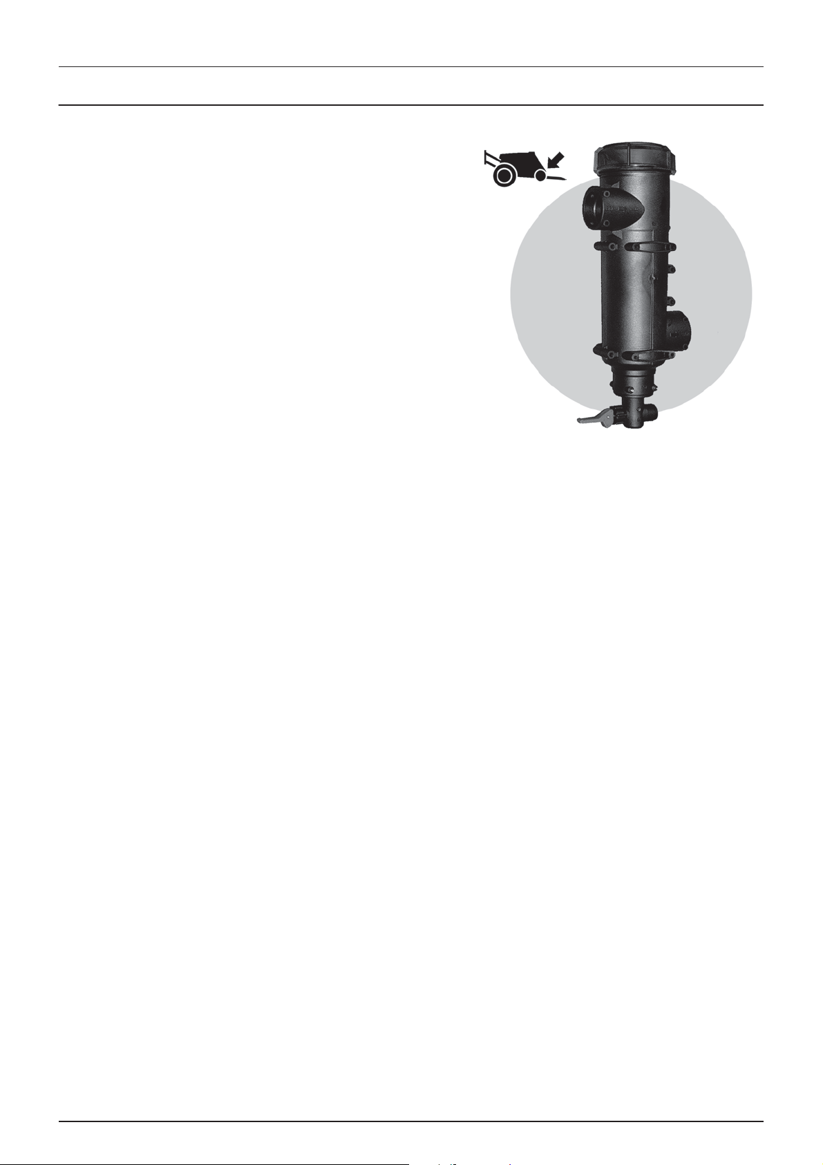
4 - Sprayer setup
Liquid system
CycloneFilter
Standard filter size is 80 mesh and can be changed by opening the filter
top. Check condition of O-rings and lubricate if necessary or replace if
damaged before reassembly.
DANGER! Never open the Cyclone filter unless the suction
€
SmartValve is turned to the unused position and the pressure
SmartValve is turned to “Main tank”. Otherwise, spraying liquid
may hit you when opening the filter, and drain from the main
tank!
48
Page 49

Boom
Damping adjustment
When altered the guide rod setting in “Suspension performance
adjustment” then it is possible to adjust more accurately in the field. This
is done with the electrical damping control, which is situated at the
centre section of the boom.
When the throttle valve (A) is screwed all the way in, followed by three
reverse turns out (factory setting), the boom suspension will react
immediately, and the boom will move independently of the trailer or
tractor.
To obtain more damping: Throttle valve (A) must be screwed inward.
To obtain less damping: Throttle valve (A) must be screwed outward.
Boom folding speed adjustment
There are restrictors for adjusting of boom folding speed - one per each
boom wing. The restrictor are located near the big pendulum damping
cylinder.
4 - Sprayer setup
Adjustment
• To decrease folding speed:
Loosen counternut (arrowed) and to adjust folding speed valve
(arrowed) must be screwed inward. Lock counternut again.
• To increase folding speed:
Loosen counternut (arrowed) and to adjust folding speed valve
(arrowed) must be screwed outwards. Lock counternut again.
ATTENTION! The system must not be pressurized during
adjustment.
Boom folding speed adjustment - 32-36 m boom only
The restrictor for adjusting of boom folding speed is located in the main
hydraulic block located behind the pendulum suspension springs.
Adjustment
• To decrease folding speed:
Loosen counternut (arrowed) and to adjust folding speed valve
(arrowed) must be screwed inward. Lock counternut again.
• To increase folding speed:
Loosen counternut (arrowed) and to adjust folding speed valve
(arrowed) must be screwed outwards. Lock counternut again.
49
Page 50

4 - Sprayer setup
TWIN Air technique
Adjusting the air assistance
The air speed and angling must always be adjusted individually for each spray job and the given weather conditions. It is
always a good idea to get used to a new sprayer out in a field with only water in the tank, on this occasion the following
routine for air adjustment should be practised:
1. Start with the air vertical
2. Set the air speed: See section “Setting of air speed, rules of thumb”
3. Find the best angling: See section “Angling of air and liquid, rules of thumb”
4. Readjust the air: See section “Setting of air speed, rules of thumb”
ATTENTION! Fine tuning of air speed and angling will often be necessary all through the spraying job.
ATTENTION! It is easiest to find the best air setting to reduce drift when the sun is low and behind the boom
(backlight). These conditions make the drift more visible.
Setting of air speed, rules of thumb
Step 1
Find the range of air speeds that can control drift
1. Start with the air setting at zero and keep increasing the air speed just to the point where you can see that the drift
cloud is minimised - note minimum setting.
2. Then increase the air speed until you see drift again - note maximum setting.
3. Now you know the range of air speeds that can be used with minimum drift.
Bare ground / low crop: The range of air speeds is usually very small.
Taller crop: The taller the crop the wider the range of air speeds that can reduce drift.
At higher wind speeds: More air is needed on the sprayer and it is advisable to drive more slowly and use minimum
boom height (40 cm)/(16 in).
Too high air speed over bare ground/low crop can cause reflection of the spray liquid and leave dust on the leaves,
which can again reduce the effect of the plant protection product.
Step 2
Set the optimal air speed within possible the range mentions above.
Air speed recommendations:
Bare ground / low crop: Use maximum air within the possible range.
Taller crop: Deeper crop penetration requires more air on the sprayer (if you are in doubt check with water sensitive
paper).
Forward speed: Higher forward speeds require more air on the sprayer.
Volume rate: Lower volume rates require more air assistance to prevent drift.
50
Page 51

4 - Sprayer setup
Angling of air and liquid, rules of thumb
To control wind drift the influence of wind speed and wind direction as well as the horizontal air current around the boom
due to forward speed must be minimised. Because it is a sum of two forces with variable direction and size that we have to
counteract for, the following can only be very rough guidelines.
Wind direction
• Head wind: Angle forward.
• Down wind: Angle back (if the forward speed is higher than the wind speed: angle forward).
• Side wind/no wind: Angle vertical or back. Only high forward speeds may require forward angling.
Crop condition
Bare ground/low vegetation: Low air speed and angling back will often be the best setting to avoid reflection of spray liquid.
Dense crop: The angling feature is ideal to help opening the canopy and improve penetration. If you follow the crop
movement as you are varying the angling you will find that at certain settings the crop will open more for penetration.
If wind speed, wind direction or for some reason forward speed changes during spraying the optimum angling is likely to
change too. Be aware that with certain combinations of air speed and angling you can “close” or flatten the crop and make
penetration impossible - follow the crop movement intensively especially when setting the air assistance and keep an eye
on the crop all through the application.
• It is most important that the sprayer operator is familiar with the above rules of thumb before using the TWIN sprayer.
• All volume rates, pressures and air adjustments stated in the following tables are, of course, guiding. Special conditions
regarding climate, crop quality, spraying time and applied chemical can change the procedure. The tables are showing
practice in north ern Europe, and conditions may be very different in other countries. I f you want some lo cal advice you
are ver y welc ome to contact the T WIN applic ation expert a t the HA RDI imp orter or daughter company in your country.
• The volume rate can generally be reduced to half of what is applied with a conventional sprayer, but with a minimum
of 50-60 l/ha at 7-8 km/h (5.5-6.5 GPA at 4.5-5 mph. Exceptions are of course liquid fertiliser and herbicides whose
selectivity is based large droplets that will only stick to the weeds.
• Low drift nozzles can also be fitted on a TWIN sprayer and help reduce drift even further.
• If there is a detailed spraying instruction on the chemical label regarding drop size, spray pressure, spray volume rate
etc. this should be followed. Enclose 1 bag of water sensitive paper and instruction of how to use with all TWIN
sprayers.
ATTENTION! Often it will be necessary to drive with two different anglings, so the angling is changed when changing
driving direction after turning at the headland.
Water sensitive paper
USE WATER SENSITIVE PAPER TO HELP FIND THE BEST AIR SETTING.
Some time spent in different types of crops with clean water in the tank and some water sensitive paper will be valuable
experience for the future work with your TWIN sprayer. The paper can be cut into smaller pieces (to simulate the target) and
fixed with double sided tape at relevant places in the crop. Then spray with pure water and check the blue spots (droplets)
on the paper. This way you can test different spraying techniques. Water sensitive paper is available at your local HARDI
dealer, part No. 893211.
51
Page 52
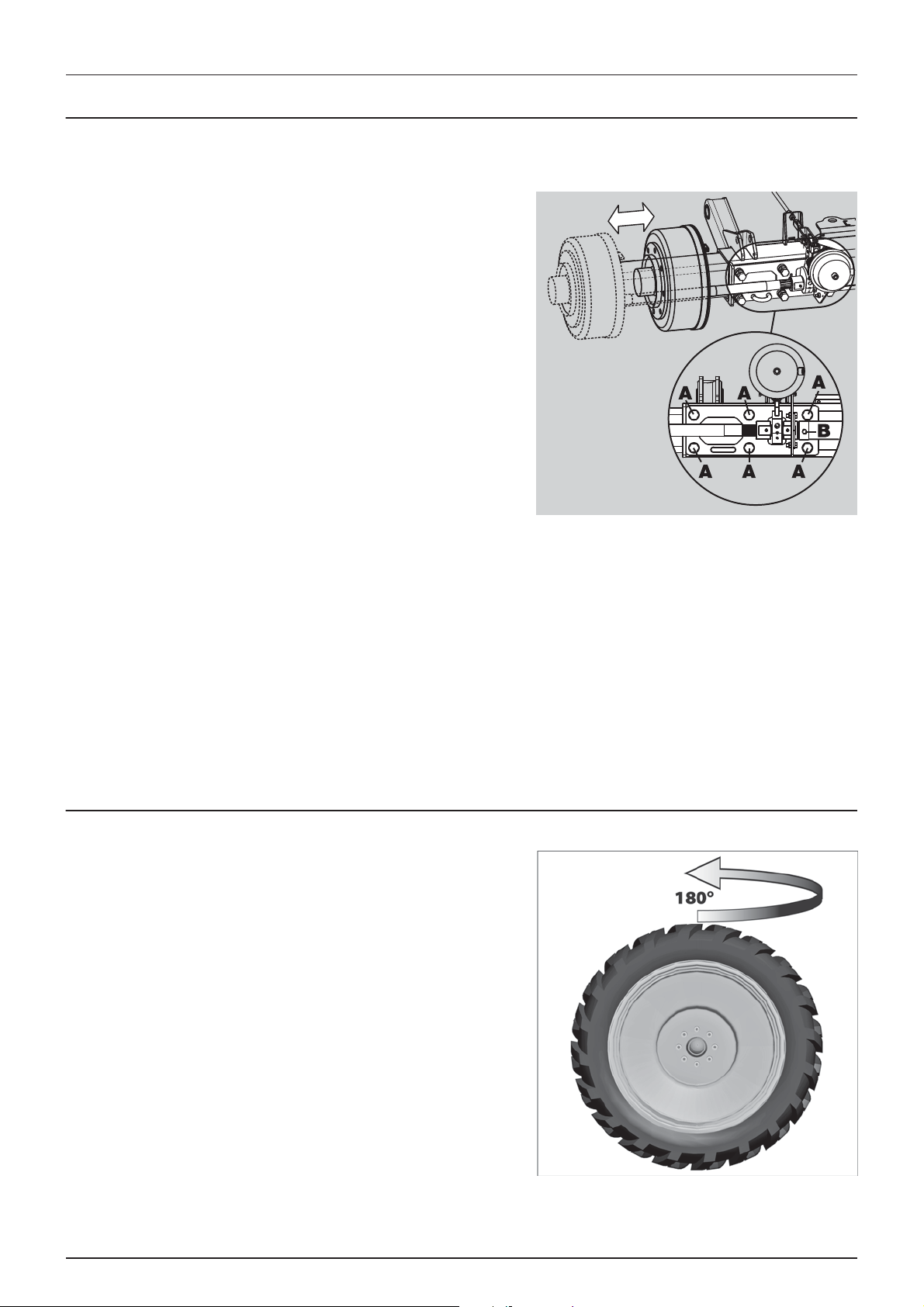
4 - Sprayer setup
Track gauge, axles and wheels
Altering the track width
The track width of the sprayer can be altered stepless as follows,
Altering procedure
1. Measure the current track width (centre RH tyre to centre LH tyre).
Each side must be extended or retracted half the desired
alteration.
2. Attach the sprayer to tractor and engage tractor parking brake.
3. Place stop wedges in front of and behind RH wheel. Jack up LH
wheel, support and secure sprayer body.
4. Loosen the counternut at the bolts (A) and the bolts (A) for LH
wheel axle.
5. When having a handbrake, loosen the pointed screw (B) on the
brake operating arm.
6. Extend or retract the axle. A sack barrow and a rod will facilitate the
operation.
7. Lower down the LH wheel.
8. Tighten the clamp bolts (A) to a torque of 250 Nm and lock the
bolts with the counternuts.
9. Repeat the procedure on RH wheel.
10. Check if the distance from centre tyre to centre of rear frame is equal at RH and LH.
11. Retighten bolts and wheel bolts to specified torque after 8 hours of work.
ATTENTION! The wider the track width, the better the stability of the sprayer. HARDI recommends to work with widest
possible track width.
ATTENTION! Depending on configuration of the machine the track width can be altered in the range from 1500 mm
to 2000 mm (narrow version), or from 1800 mm to 2250 mm (wide version) in combination of above adjustment and
turning of the rims (offset).
Turning rim
Track width can be altered by turning the rim.
Offset:
+ 61 mm
- 50 mm
ATTENTION! When wheels has been mounted or re-tightened,
the plastic nut covers must be placed on the nuts afterwards.
52
Page 53

Counter weight
To improve stability on articulated models, extra weight can be added
by means of liquid-filled tyres. The standard tyre valve is an universal airwater valve. The tyres can be filled with liquid to max. 75% of their total
volume.
4 - Sprayer setup
Use a mixture of water and CaCl
below:
200 g (7.1 oz) CaCl
300 g (10.6 oz) CaCl
435 g (15.4 oz) CaCl
To fill the tyres
1. Jack up the wheel and rotate wheel till the valve is positioned at
“12 o’clock”.
2. Remove the valve body and fill liquid until it reaches the valve.
3. When surplus liquid is drained through the valve stem fit the valve
body again.
4. Adjust tyre pressure and lower the wheel. Please refer to “ Tyre
pressure” on page 118.
DANGER! It is very important that the CaCl2 is added to the water and agitated until it is fully dissolved. Never pour
€
water on to CaCl
advice afterwards.
WARNING! The tyres must be liquid filled to max. 75 % of total tyre volume. Fill only the qty. of liquid necessary to
±
obtain sufficient stability of the sprayer. Do not fill liquid and CaCl
per litre water gives protection to -15°C (30.6°F)
2
per litre water gives protection to -25°C (12.6°F)
2
per litre water gives protection to -35°C (-5.4°F)
2
! If you get CaCl2 in the eyes, flush instantly with cold water for at least 5 minutes and seek medical
2
to avoid frost damage as described
2
mixture in tyres without tubes!
2
ATTENTION! When filling the tyres the valve should be positioned at 12 o’clock and when adjusting the tyre pressure,
the valve should be positioned at 6 o’clock.
To empty the tyres
1. Rotate wheel till the valve is positioned at “6 o’clock”.
2. Remove the valve body and let out the liquid. Retain liquid in an
appropriate container.
3. To empty the tyre completely the tyre is inflated and a thin drain
tube is lead to the bottom of the tyre. The air pressure will now
empty the remaining liquid.
4. Remove the drain tube, fit the valve and inflate the tyre to specified
pressure. See “Technical specifications” for the table “Tyre pressure”.
ATTENTION! Disposal of CaCl2 has to take place according to local legislation.
53
Page 54
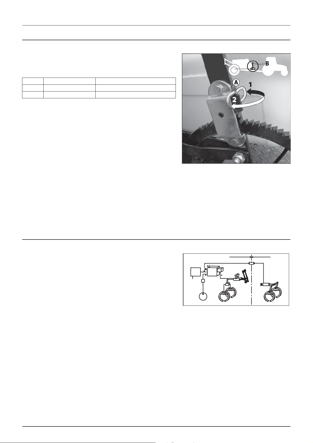
4 - Sprayer setup
Brakes
Emergency and parking brake
The parking brake lever has two function modes, which are determined
by the small pawl control clip (A). To change between the two modes,
turn the clip.
Position Rest position Behavior
1 Rest against the pawl Disengage parking brake
2 Point away from the pawl Engage parking brake/Emergency brake
Disengage the parking brake
1. Set pawl control clip in position 1.
2. Pull the lever a little forward to release the pawl from the ratchet
and then push the lever fully backwards.
Engage the parking brake
1. Set pawl control clip in position 2.
2. Pull the lever firmly forwards until parking brake is fully engaged.
Emergency brake
1. Set pawl clip in position 2.
2. Attach the rope from the hole in top of the hand brake lever to e.g. the tractor top link attaching point (B). If the sprayer
is accidentally unhooked during transport the rope will apply the parking brake before the rope breaks.
ATTENTION! To ensure safe engagement and to avoid damages to the parking brake use rope with an ultimate stress
between 690 N (155 lb.) and 785 N (176 lb.).
WARNING! Relieve the parking brake before driving!
±
Hydraulic activated brakes
This requires a special trailer brake valve attached to the tractor hydraulic
and brake system. Connect the snap coupler to the tractor brake outlet.
When the tractor brakes are applied, the trailer brakes will work
proportionally to the tractor brakes, and ensure safe and effective
braking.
WARNING! Do not connect the brakes directly to the tractor
±
hydraulics without the brake valve. The trailer brake power
cannot be controlled, and braking will therefore be hazardous.
WARNING! Max. oil pressure is 150 bar (2175 p.s.i.) in the brake line.
±
54
Page 55

4 - Sprayer setup
Air activated brakes (optional)
This system requires a tractor with compressor and air brake system with
outlet(s) for trailer brakes.
If the air hose(s) are disconnected with air in the brake air tank, control
pressure will be dumped and the brakes will engage fully.
If the sprayer e.g. must be moved, the load apportioning valve must be
set. Remember to reset the handle to brake position again afterwards.
Position State Use
1 Relieved Move sprayer with air in the tank and without the air hose(s)
connected to the tractor. Disengages the brakes.
2 Full Use when driving with full tank.
3 Half full* Use when driving with tank half full.
4 Empty Use when driving with empty tank.
*If axle load exceeds 5250 kg. position 2 is required to be used.
ATTENTION! When parking the sprayer, always engage the parking brake, as the air brakes will only be engaged as
long as there is air in the tank! Cover the couplings with the dust flaps when hoses are disconnected.
ATTENTION! The load apportioning valve must be set at the position corresponding to the load on the trailer, for
obtaining optimal air pressure to the trailer brakes.
WARNING! Driving with wrong load apportioning valve setting, will make the brakes under or over apply, which can
±
cause hazardous situations.
Single-line brakes (optional)
1. Flip the snap coupler protection flap away.
2. Connect the snap coupler to the tractor outlet (black).
3. Let the compressor fill the sprayer’s air reservoir.
4. Check brake circuit for leaks.
Dual-line brakes (optional)
1. Flip the snap coupler protection flaps away.
2. Connect the two snap couplers for supply and control to the tractor outlets. The couplers are colour coded and
secured against incorrect attachment:
Red Supply line (RH)
Yellow Control line (LH)
3. Let the compressor fill the sprayer’s air reservoir.
4. Check brake circuits for leaks.
55
Page 56

4 - Sprayer setup
56
Page 57

General info
Environmental info
For environmental info, please refer to the following parts in the Spray Technique book:
• Nozzles.
• Spray quality.
• Choosing Nozzles for arable crops.
• Spraying speed.
5 - Operation
57
Page 58

5 - Operation
Boom
Safety info
The boom must not be folded/unfolded while driving! Never use the folding/unfolding functions before the sprayer has
been stopped! Failure to do so will damage the boom.
DANGER! Before unfolding the boom it is important to connect the sprayer to the tractor to prevent overbalancing
€
of the sprayer.
DANGER! When folding or unfolding the boom, make sure that no persons or objects are within the operating area
€
of the boom.
DANGER! Always follow the guidelines listed below when driving in areas with overhead power lines:
€
Never use the folding/unfolding functions in areas with overhead power
lines.
Unintended boom movements may cause contact with overhead
power lines.
ATTENTION! A label (ref. no. 978448) follows the sprayer. This label
must be placed in the cabin visible from the operator’s seat.
ATTENTION! Only unfold and fold the boom on level ground.
Manoeuvring of the boom - HAY
The boom unfolding/folding can be done according to instructions below.
1. Lift up the boom lift until the boom is clear of the transport brackets using the single acting hydraulic outlet lever.
2. Unfold the boom completely using the double acting hydraulic outlet lever.
3. Lower the boom to correct working height above the ground/crop 50 cm/20 in.
4. Release the pendulum lock on the spray box switch. Folding is to be done in reverse order (Pendulum must be locked
before folding).
ATTENTION! Only unfold and fold the boom on level ground.
58
Page 59
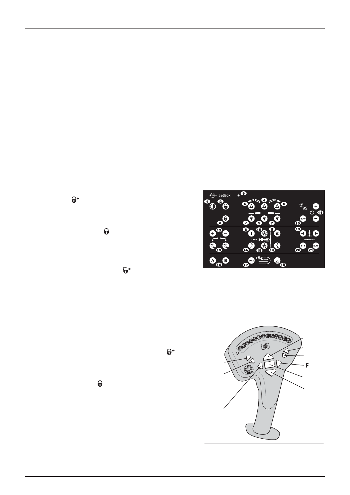
Manoeuvring of the boom - HAZ
A
B
C
D
E
H
G
I
5 - Operation
WARNING !
±
possible if the pendulum is unlocked. A manual override of the pendulum lock is possible by activating switches 2 or 3.
WARNING! Ensure that transport safety chains are removed and the boom is clear from the transport brackets before
±
unfolding.
WARNING! The folding functions must only be operated when the sprayer is stationary! Failure to do so will damage
±
the boom. The pendulum lock automatically opens at speeds exceeding 1.5 km/h!
ATTENTION! The boom can not be operated with the tractors hydraulic levers.
Only buttons relevant for boom functions are mentioned here. Refer to “SetBox controls” on page 29 for descriptions
of other buttons.
To unfold the boom
WARNING! The pendulum lock automatically opens when you begin to drive. Drive slowly until the pendulum is
±
completely unlocked.
1. Push the lift up button (H) to lift the boom clear of the transport
brackets. The symbol appears in display until pendulum is
locked. This takes approximately 10 seconds.
2. Push the button (5) to unfold the inner wings completely
(approximately 5 seconds or a warning will appear). Check that the
pendulum locked symbol is visible in the display.
The pendulum lock automatically turns ON when pressing one of the folding buttons. Boom folding is not
3. Push the buttons (7) to unfold the 1st outer wings.
4. Push the lift down button (I) to lower the boom to the correct
working height.
5. If not unlocked, then press (2) and symbol appears in display
until pendulum is unlocked. This takes approximately 10 seconds.
To fo l d th e bo o m
WARNING! If having SafeTrack is must be aligned and locked before folding.
±
1. Push slant buttons (E) or (F) to set neutral slant angle (no slant).
2. Push lift up button (H) to raise the boom to the highest possible
position.
3. Push the buttons (6) to fold the 1st outer wings. The symbol
appears in display until pendulum is locked. This takes
approximately 10 seconds.
4. Push the button (4) to fold the inner wings. Check that the
pendulum lock symbol is visible in the display.
5. Push the lift down button (I) to lower the boom until it rests in the
paralift locks.
6. Push tilt down buttons (B) and (D) to lower the individual tilt rams
until they rest on the front transport brackets.
59
Page 60

5 - Operation
Hydraulic slanting control
Z-models
The hydraulic boom slanting controls (E) and (F) enables slanting of the entire boom hydraulically. This is advantageous
when spraying across hillsides.
Reset position to neutral (midway) before folding the boom.
Y-models (optional)
Use the tractor’s hydraulic lever to slant the entire boom hydraulically.
Reset position to neutral (midway) before folding the boom.
Boom tilt function
The boom tilt function controls () and () enables you to adjust the boom height individually in right and left-hand side.
2/3 boom width
Alternative boom widths can be obtained by folding outer section(s). The pendulum must always be locked if driving with
only one outer section folded in position.
WARNING! Use caution if driving with locked pendulum, and only do so on level ground. Reduce the period of driving
±
with locked pendulum to a minimum of time, as this setting reduces the life time of the boom.
Half boom width
It is possible to spray with boom only half unfolded. In case this is needed then only unfold inner sections by pressing
downwards. On the spray control unit also turn off the spray sections placed on outer boom sections.
Hydraulic breakaway function
The boom has a hydraulic breakaway function built-in to protect from damage if e.g. it hits the ground. If this function is
being activated by obstruction, an alarm will appear into the controller. The alarm will continue until the boom has been
folded out to complete retracted position by pressing (7) again.
60
Page 61

5 - Operation
TWIN Air technique
TWIN operation
The air speed and angling must always be adjusted individually for each spray job and the given weather conditions.
The buttons on the SetBox controls the following:
1. Power ON/OFF
8. TWIN presets
14. TWIN angling
15. TWIN air volume (fan speed)
ATTENTION! For function of other switches see “SetBox controls”
on page 29.
Pressing the buttons (14)
• Air slot and nozzle assembly can be angled in steps zero to 4 backwards and from zero to 6 forwards, which is
corresponding to approx. 30° backwards and 40º forwards compared to vertical position. Regarding adjustments - see
section on “Air technique”.
Pressing the buttons (15)
• Air speed can be adjusted in steps from zero to 10. The blower revolutions can be viewed in the controller display. The
max. revolutions for the fan is 3100 r.p.m., which will give full air speed of approximately 40 m/s. When booms are halffolded, reduce r.p.m. or pressure with 25% to obtain the same performance (air speed at nozzles).
61
Page 62

5 - Operation
Liquid system
Filling/washing location requirements
When filling the sprayer with chemicals and water it is important to avoid spot contamination by spray chemicals in order
to protect the subsoil water resources.
A. If the sprayer is always filled at the same place, a special filling/washing location should be established. This should
have a hard, liquid-impenetrable surface (e.g. concrete) securing against seepage and edges securing against run-off
to the surrounding areas. The place should be drained to an adequate receptacle (e.g. slurry tank or similar).
Any spillage or washings should be retained and diluted in order to be distributed on a larger area to ensure minimal
environmental impact and avoid build-up of larger chemical concentrations at one spot.
If no other requirements of distances exist, the following general recommendation of distance could be used. Not
closer than:
1) 50 metres from public water supplies for drinking purposes,
2) 25 metres from non-public water supplies for drinking purposes and from treatment sumps and cesspools of
drainage systems, and
3) 50 metres from surface water (watercourses, lakes and coastal waters) and from nature reserves.
B. Alternatively the sprayer can be filled in the field where the spraying is to take place. If so, choose a different location
for each refilling.
If no other requirements of distances exist, the filling should not take place closer than:
1) 300 metres from public or non-public water supplies for drinking purposes and
2) 50 metres from surface water (watercourses, lakes and coastal waters), treatment sumps, cesspools of drainage
systems, and nature reserves.
ATTENTION! Legislation and requirements vary from country to country. Always follow local legislation in force at any
time.
NOTE! It is the responsibility of the sprayer owner/operator to comply with all relevant legislation. HARDI cannot
÷
undertake any responsibilities for incorrect operation and use.
Filling of water
The tank should normally be filled 1/3 with water before adding
chemicals. Always follow the instructions given on the chemical
container!
WARNING! If the sprayer is put aside with liquid in the main tank,
±
all MANIFOLD valves must be closed.
62
Page 63

5 - Operation
Filling through tank lid
Water is filled into the tank by removing the tank lid located at front of the sprayer tank which is accessible from the platform.
It is recommended to use as clean water as possible for spraying purposes. Always fill water through the strainer basket to
prevent foreign particles from entering the tank. An overhead tank can be used in order to obtain high filling capacity.
WARNING! Do not let the filling hose enter the tank. Keep it
±
outside the tank, pointing towards the filling hole. If the hose is
led into the tank and the water pressure drops at the water
supply plant, chemicals may be siphoned back and contaminate
the water supply lines, plant and well.
WARNING! The water supply line should be provided with a check
±
valve as additional safety precaution. Follow local legislation in
force at any time.
WARNING! The water supply should be provided with a meter to avoid spillage by over-filling. Follow local legislation
±
in force at any time.
Filling of rinsing tank
The rinsing tank is filled via the 1” threaded connection piece at the valve system:
1. Remove the filler cap, then fit the external water hose to the threaded connection piece.
2. Engage external water pump, if any.
3. Keep an eye on the level indicator in order not to overfill the tank.
4. Stop filling and refit the cap.
Capacity: approximately 450 litres.
ATTENTION! Only fill rinsing tank with clean water! To avoid algae developing in the rinsing tank always drain the
rinsing tank if the sprayer is not in use for a longer period of time.
ATTENTION! For cleaning purposes etc. the rinsing tank is also accessible via the tank lid on top of tank.
Filling of clean water tank
To fill the clean water tank:
1. Remove the tank lid
2. Fill with clean water
3. Reposition the tank lid.
For use of water:
• Turn the ball valve lever to open. The ball valve is located on the
valve cover.
The water from this tank is for hand washing, cleaning of clogged
nozzles etc. Only fill the clean water tank with clean water from the well.
WARNING! Although the clean water tank is only filled with clean water, this water must NOT be used for drinking.
±
63
Page 64

5 - Operation
External Filling Device
The External Filling Device is operated as follows:
1. Remove cover and connect suction hose to Suction Manifold.
2. Close the agitation valve, turn pressure SmartValve to “Main tank”.
3. Engage diaphragm pump and set P.T.O. revolutions at 540 r/min or
1000 r/min depending on pump model.
4. Turn handle on External Filling Device valve towards Filling Device.
5. The tank is now filled with water. Keep an eye on the liquid level
indicator.
6. Turn handle on Suction Manifold away from Filling Device to
discontinue filling process. Then disengage pump.
7. Disconnect suction tube and replace cover.
DANGER! Avoid contamination or personal injury. Do not open suction valve towards Suction Filling Device unless
€
pump is running and filling hose is connected. If this valve is opened without pump running, liquid will stream out
of the coupler.
WARNING! Do not leave the sprayer whilst filling the tank and keep an eye on the level indicator in order NOT to
±
overfill the tank.
WARNING! If suction hose/filter is carried on the sprayer during spraying, it can be contaminated by spray drift which
±
will be transferred to lake/river when filling!
ATTENTION! Observe local legislation regarding use of filling device. In some areas it is prohibited to fill from open
water reservoirs (lakes, rivers etc.). It is strongly recommended only to fill from closed reservoirs (mobile water tanks
etc.) to avoid contamination.
64
Page 65

5 - Operation
Safety precautions - crop protection chemicals
Always be careful when working with crop protection chemicals!
WARNING! Always wear proper protective clothing before handling chemicals!
±
Personal protection
Depending on chemical type, protective gear/equipment should be worn to avoid contact with the chemicals, e.g.:
• Gloves
• Waterproof boots
• Headgear
• Respirator
• Safety goggles
• Chemical resistant overall
WARNING! Protective clothing/equipment should be used when preparing the spray liquid, during the spray job and
±
when cleaning the sprayer. Follow the chemical manufacturer’s instructions given on the chemical label and/or local
legislation.
WARNING! It is always advisable to have clean water available, especially when filling the sprayer with the chemical.
±
WARNING! Always clean the sprayer carefully and immediately after use.
±
WARNING! Only mix chemicals in the tank according to directions given by the chemical manufacturer.
±
WARNING! Always clean the sprayer before changing to another chemical.
±
Filling chemicals through tank lid
The chemicals are filled through the tank lid - Note instructions on the chemical container!
WARNING! Be careful not to slip or splash chemicals when carrying chemicals up to the tank lid!
±
ATTENTION! Due to risk of spillage and spot contamination it is not allowed in several countries to fill chemicals
directly through the tank lid. Use the TurboFiller for all induction of chemicals instead.
1. Make sure the spray control unit is switched off.
2. Set suction valve towards “Suction from main tank”, Agitation valve
towards “Agitation”. Other valves should be closed or turned to
unused function.
3. Engage the pump and set P.T.O. revolutions to 540 r/min or 1000
r/min depending on pump model.
4. Add the chemicals through the main tank hole.
5. When the spray liquid is well mixed, turn handle on the pressure
SmartValve towards “Spraying” position. Keep P.T.O. engaged so the spray liquid is continuously agitated until it has
been sprayed on the crop.
DANGER! Before turning Pressure SmartValve to “Pressure draining/TurboFiller” it is very important to be sure that the
€
quick coupler lid is correct and completely mounted to the filling stud into its locked position. Failure to do so may
cause risk of contamination and injury from quick coupler lid being “shot” off when pressurized! If not possible to
mount lid completely, lubricate the rubber seal and the grip hooks.
NOTE! Local legislation may not allow filling through the tank lid, but will require use of the chemical inductor instead.
÷
65
Page 66
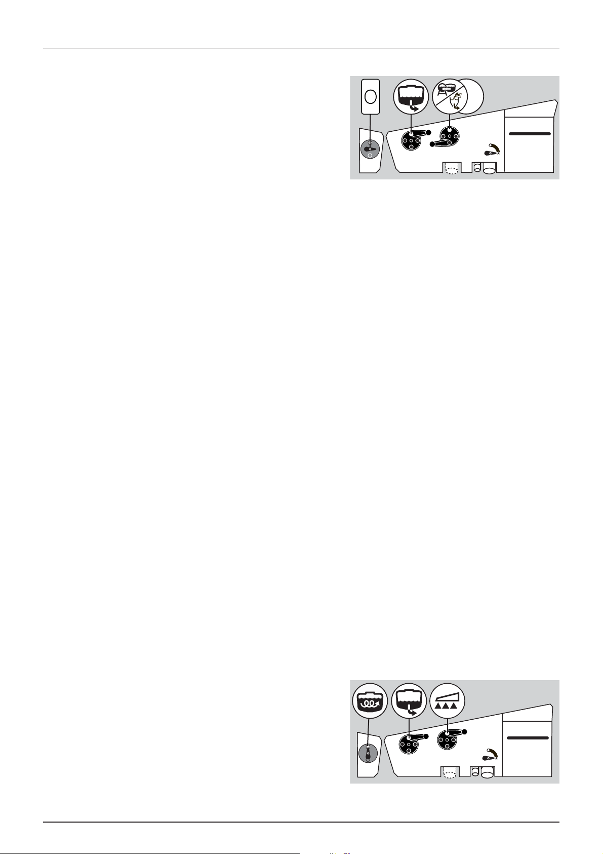
5 - Operation
Filling liquid chemicals by HARDI TurboFiller
1. Fill the main tank at least 1/3 with water (unless otherwise stated
on the chemical container label).
2. Turn the handle of the suction valve towards “suction from Main
tank”. Turn pressure SmartValve towards “Pressure
draining/TurboFiller”. Close the AgitationValve.
NOTE! If filling water from an external tank, this can be continued
÷
while doing the next steps.
DANGER! Before turning Pressure SmartValve to “Pressure draining/TurboFiller” it is very important to be sure that the
€
quick coupler lid is correct and completely mounted to the filling stud into its locked position. Failure to do so may
cause risk of contamination and injury from quick coupler lid being “shot” off when pressurized! If not possible to
mount lid completely, lubricate the rubber seal and the grip hooks.
3. Engage the pump and set P.T.O. speed at 540 r/min or 1000 r/min (depending on pump model).
4. Open TurboFiller lid. Measure the correct quantity of chemical and fill it into the hopper.
DANGER! Always wear face shield and other appropriate personal safety equipment when filling chemicals.
€
ATTENTION! The scale in the hopper can only be used if the sprayer is parked on level ground! It is recommended to
use a measuring jug for best accuracy.
5. Engage the hopper transfer device by opening the TurboFiller suction valve transfer chemicals to the main tank. The
TurboFiller suction valve must be open for at least 20 seconds after the chemical is no longer visible in the hopper in
order to completely empty the transfer hoses into the main tank.
DANGER! If the TurboFiller and the transfer hoses are not completely emptied there are risk of chemicals being
€
siphoned out of the main tank!
6. If the chemical container is empty, it can be rinsed by the Chemical Container Cleaning device. Place the container
over the multi-hole nozzle and push the container cleaning.
DANGER! In order to avoid spray liquid hitting the operator, do not press lever unless the multi-hole nozzle is covered
€
by a container as spray liquid may otherwise hit the operator!
ATTENTION! Rinsing device uses spray liquid to rinse containers for concentrated chemicals. Always rinse the
chemical containers with clean water several times until they are clean before disposal.
7. Flush the TurboFiller with clean water from the Rinsing tank. The TurboFiller suction valve must be open for at least 20
seconds after the rinse water is no longer visible in the hopper in order to completely empty the transfer hoses into
the main tank.
ATTENTION! If not flushed with clean water, the hopper rinsing device uses spray liquid for rinsing the hopper!
Cleaning the TurboFiller must always be done when the spray job is ended and together with the entire sprayer - a
cleaning after the last filling and before spraying the last tankful does not ensure a clean TurboFiller!
8. Close TurboFiller suction valve when the hopper has been rinsed and close the lid.
9. Turn the AgitationValve towards “Agitation”.
10. When the spray liquid is well agitated, turn handle of the pressure
SmartValve towards “Spraying” position. Keep P.T.O. engaged so
the spray liquid is continuously agitated until it has been sprayed
on the crop.
66
Page 67

5 - Operation
Filling powder chemicals by HARDI TurboFiller
1. Fill the main tank at least 1/2 with water (unless otherwise stated
on the chemical container label). See section “Filling of water”.
2. Turn the handle of the suction valve towards “suction from Main
tank”. Turn pressure SmartValve towards “Pressure
draining/TurboFiller”. Turn the AgitationValve towards “Agitation” if
required. Close remaining valves.
ATTENTION! For increased suction from the TurboFiller the
AgitationValve can be kept closed.
NOTE! If filling water from an external tank, this can be continued while doing the next steps.
÷
DANGER! Before turning Pressure SmartValve to “Pressure draining/TurboFiller” it is very important to be sure that the
€
quick coupler lid is correct and completely mounted to the filling stud into its locked position. Failure to do so may
cause risk of contamination and injury from quick coupler lid being “shot” off when pressurized! If not possible to
mount lid completely, lubricate the rubber seal and the grip hooks.
3. Engage the pump and set P.T.O. speed at 540 r/min or 1000 r/min (depending on pump model).
4. Open TurboFiller lid. Open TurboDeflector valve and TurboFiller suction valve.
5. Measure the cor rect quant ity of chemi cal and spri nkle it into the hopper as fast as the trans fer device can flush it d own.
The TurboFiller suction valve must be open for at least 20 seconds after the chemical is no longer visible in the hopper
in order to completely empty the transfer hoses into the main tank.
DANGER! If the TurboFiller and the transfer hoses are not completely emptied there are risk of chemicals being
€
siphoned out of the main tank!
DANGER! Always wear face shield and other appropriate personal safety equipment when filling chemicals.
€
6. If the chemical container is empty, it can be rinsed by the Chemical Container Cleaning device. Place the container
over the multi-hole nozzle and push the upper lever to the left of the TurboFiller.
DANGER! In order to avoid spray liquid hitting the operator, do not press lever unless the multi-hole nozzle is covered
€
by a container as spray liquid may otherwise hit the operator.
ATTENTION! Rinsing device uses spray liquid to rinse containers for concentrated chemicals. Always rinse the
chemical containers with clean water several times until they are clean before disposal.
7. Flush the TurboFiller with clean water from the Rinsing tank. The TurboFiller suction valve must be open for at least 20
seconds after the rinse water is no longer visible in the hopper in order to completely empty the transfer hoses into
the main tank.
ATTENTION! If not flushed with clean water, the hopper rinsing device uses spray liquid for rinsing the hopper!
Cleaning the TurboFiller must always be done when the spray job is ended and together with the entire sprayer - a
cleaning after the last filling and before spraying the last tankful does not ensure a clean TurboFiller!
8. Close TurboFiller suction valve when the hopper has been rinsed and close the lid.
9. If closed, turn the AgitationValve towards “Agitation”.
10. When the spray liquid is well agitated, turn handle of the pressure
SmartValve towards “Spraying” position. Keep P.T.O. engaged so
the spray liquid is continuously agitated until it has been sprayed
on the crop.
67
Page 68

5 - Operation
TurboFiller rinsing
Rinsing the TurboFiller and chemical containers are done as follows:
Cleaning empty containers - TurboFiller lid is open
1. Put container over the rotating flushing nozzle in the middle of the
TurboFiller so that the nozzle is inside the container.
2. Simultaneously press the Chemical Container Cleaning lever and
the TurboFiller suction valve. This rinses the chemical container
with the flushing nozzle while the rinsing liquid is emptied out of
the TurboFiller.
TurboFiller rinsing - TurboFiller lid is closed
1. Close TurboFiller lid.
2. Turn the suction SmartValve towards “Rinsing tank” or “External Filling Device” if clean water is available here.
3. Simultaneously press the Chemical Container Cleaning lever and the TurboFiller suction valve. This rinses the hopper
with the flushing nozzle while the rinsing liquid is emptied out of the TurboFiller.
4. Rinse the hopper for 30-40 seconds.
5. Open the lid to inspect if the TurboFiller is empty. If not, close the lid again and press the TurboFiller suction valve until
the TurboFiller is empty.
6. After the last flushing the TurboFiller suction valve must be open for at least 20 seconds after the rinse water is no
longer visible in the hopper in order to completely empty the transfer hoses into the main tank.
ATTENTION! The TurboFiller needs to be cleaned thoroughly after finishing spraying again to be sure it is clean before
spraying other crops that may be sensitive to the chemicals just used. See section “Cleaning” on page 72 for details.
68
Page 69

Operating the control units while spraying
The control units control the following spray functions:
1. Power ON/OFF/status LED. LED must be ON.
2. Automatic spray pressure regulation.
The regulation valve controls the main spray pressure. This is
default selection when the controller is powered ON, and it should
remain here during normal spraying.
3. Manual spray pressure regulation. Under normal spraying these
should not be used as the regulation valve does this automatically.
4. Foam marker blob interval. Regulates the blob interval for the
optional foam marker.
5. Foam marker (Left/Right). Turns the optional foam marker ON for
each side.
6. Optional function (A/B). If extra equipment is added, it can be controlled from here.
A. Power ON/OFF/status LED. LED must be ON.
B. Section valves. Turns single sections on or off. Lever up is OFF and
down is ON.
5 - Operation
C. Main valve ON/OFF.
Use when spraying
• On the sprayer, turn the suction valve toward “Suction from Main
tank” and the pressure SmartValve toward “Spraying”. Turn the
agitation valve to “Agitation” if necessary.
• In order to close the entire boom, switch main ON/OFF (C) to OFF
position. This returns the pump output to the tank through the
return system. The diaphragm Non-drip valves ensure
instantaneous closing of all nozzles.
• In order to close one or more sections of the boom, switch the
relevant distribution valve (B) to OFF position (upwards). The
pressure equalisation ensures that the pressure does not rise in the sections that remain open.
NOTE! For checking the volume application rate, please refer to the spray controller instruction book.
÷
69
Page 70

5 - Operation
Before returning to refill the sprayer
If the sprayer is to be refilled at the farm or at a fixed filling place without a filling space with hard surface and drain to closed
reservoir, the sprayer should be rinsed before returning to refill.
Dilute the residues of the spraying circuit, and spray it on the crop. Then rinse the sprayer on the outside with the External
Cleaning Device before returning to the farm.
WARNING! Always follow local legislation in force at any time.
±
Agitation before resuming a spray job
If a spray job has been interrupted for a while, severe sedimentation may
occur depending on the chemicals being used. Before resuming the
spray job, it might be necessary to agitate sediment material.
1. Turn the handle at the suction valve towards “Suction from main
tank”. Turn the pressure SmartValve towards “Pressure
draining/TurboFiller” and turn the Agitation valve towards
“Agitation”. Other valves closed.
2. Engage the pump and set P.T.O. speed at 540 r/min or 1000 r/min
(depending on pump model).
3. Agitation has started and should be continued for at least 10 minutes.
4. The spray job can now be resumed. Turn pressure SmartValve towards “Spraying” and start spraying.
DANGER! Before turning Pressure SmartValve to “Pressure draining/TurboFiller” it is very important to be sure that the
€
quick coupler lid is correct and completely mounted to the filling stud into its locked position. Failure to do so may
cause risk of contamination and injury from quick coupler lid being “shot” off when pressurized! If not possible to
mount lid completely, lubricate the rubber seal and the grip hooks.
Parking the sprayer
To avoid spot contamination the sprayer should always be parked at either the washing/filling place or under roof. This avoid
rainfall to flush down chemical residues from the sprayer's surfaces.
• Parking at the washing/filling location will retain residues.
• Always park the machine out of reach of children, animals or unauthorized persons.
70
Page 71

Quick reference - Operation
In the following diagrams handle positions for different options are described.
5 - Operation
71
Page 72

5 - Operation
Cleaning
General info
In order to derive full benefit from the sprayer for many years the following service and maintenance program should be
followed.
ATTENTION! Always read the individual paragraphs. Read instructions for service/maintenance jobs carefully before
starting on the job. If any portion remains unclear or requires facilities which are not available, then for safety reasons
please leave the job to your HARDI dealer’s workshop.
ATTENTION!
Clean sprayers are safe sprayers.
Clean sprayers are ready for action.
Clean sprayers cannot be damaged by pesticides and their solvents.
Guidelines
1. Read the whole chemical label. Take note of any particular instructions regarding recommended protective clothing,
deactivating agents, etc. Read the detergent and deactivating agent labels. If cleaning procedures are given, follow
them closely.
2. Be familiar with local legislation regarding disposal of pesticides washings, mandatory decontamination methods, etc.
Contact the appropriate authority if you are in doubt.
3. Pesticide washings can usually be sprayed out on the field just sprayed or at a suitable cultivated area. Avoid emptying
the washings at the same spot every time and keep sufficient distance to the water environment. You must prevent
seepage or runoff of residue into streams, water courses, ditches, wells, springs, etc. The washings from the cleaning
area must not enter sewers. Alternatively the washings can be retained in an appropriate receptacle, diluted and
distributed over a larger cultivated area - see also “Filling/washing location requirements” on page 62.
4. Cleaning starts with the calibration, as a well calibrated sprayer will ensure the minimal amount of remaining spray
liquid.
5. It is good practice to clean the sprayer immediately after use and thereby rendering the sprayer safe and ready for the
next pesticide application. This also prolongs the life of the components. It is strongly advised to perform an internal
cleaning of the sprayer when high concentration of acids or chloride are present in the active ingredients, or if the spray
liquid is corrosive. For the best result use a cleaning agent recommended by Hardi, e.g. AllClearExtra.
6. It is sometimes necessary to leave spray liquid in the tank for short periods, e.g. overnight, or until the weather becomes
suitable for spraying again. Unauthorized persons and animals must not have access to the sprayer under these
circumstances.
7. If the product applied is corrosive, it is recommended to coat all metal parts of the sprayer before and after use with a
suitable rust inhibitor.
8. The sprayer must always be parked under roo f to avoid rain washing off pes ticide s and build -up of spot contamination
in the soil. If parked outside the sprayer should be parked on the filling/washing location in order to retain possible
pesticides.
72
Page 73

Quick reference - Cleaning
1/6
1/6
4 x 1/64 x 1/6
A
B
C
D
E
F
5 - Operation
A. Full agitation.
B. Wait 3 seconds before changing valve position.
C. Min. 45 seconds with nozzles OFF.
D. Spray until air comes out of nozzles. Engage FlexCapacity pump.
E. Min. 45 seconds with nozzles OFF.
F. Spray until air comes out of nozzles.
73
Page 74

5 - Operation
Cleaning and maintenance of filters
Clean filters ensure:
• Sprayer components such as valves, diaphragms and operating unit are not hindered or damaged during operation.
• Nozzle blockades do not occur whilst spraying.
• Long life of the pump. A blocked suction filter will result in pump cavitation. The main filter protecting sprayer
components is the suction filter. Check it regularly.
Use of rinsing tank and rinsing nozzles
The incorporated rinsing tank can be used for three different purposes:
A. Full internal rinsing or cleaning.
B. External cleaning (can only be carried out on completion of “A”).
C. Rinsing spray circuit without diluting main tank content.
ATTENTION! The cleaning procedures stated requires the TurboFiller to be cleaned on beforehand (directly after the
last chemical filling). If the TurboFiller for some reason is not cleaned please carry out this cleaning before attempting
the cleaning procedures A, B or C - see “TurboFiller rinsing” on page 68.
Note that this cleaning will then use water from the rinsing tank reducing the available quantity for cleaning
procedures A, B or C.
ATTENTION! Do NOT fill any cleaning detergents into the rinsing tank. If cleaning agents are to be used this should
be added the main tank.
A. Full internal rinsing
In-field diluting of remaining spray liquid residues in the spraying circuit for spraying the liquid in the field, before cleaning
the sprayer.
NOTE! This rinsing is adequate/sufficient when the sprayer is going to be used again shortly (E.g. next day) in same or
÷
similar crops (No risk by cross contamination and subsequent crop damages).
WARNING! If the next crop to be sprayed is sensitive to the latest chemical used a full cleaning should be carried out.
±
See “Full internal cleaning (Soak wash)” on page 76.
WARNING! Never clean the sprayer if there are risks of contamination of surface or underground water! Choose a
±
different spot for cleaning every time to avoid spot contamination to build up.
DANGER! Before commencing this rinsing procedure ensure that the blind cap is securely fitted and tightened on the
€
PressureEmpty quick-coupler! If this is not fitted and tightened properly it may burst off during the rinsing process
and lead to personal injuries to the operator or persons in proximity of the machine!
This rinsing procedure will rinse the spraying circuit and main tank as follows:
1. Empty the sprayer as much as possible. Close the agitation valve (no agitation). Allow the pump to run for at least 1
minute after the liquid fan from the nozzles has collapsed to ensure that all relevant liquid has been expelled.
2. Turn suction SmartValve towards “Rinsing tank” and pressure SmartValve towards “Main tank”. Set agitation valve to
“Full agitation”.
3. Engage and set the pump at approximately 300 rpm.
4. Use 1/6 (approximately 75 l) of the rinsing tank content at this valve setting.
5. Turn the pressure SmartValve towards “Pressure Empty/TurboFiller” for minimum 3 seconds to burst and flush the
safety valve. The TurboFiller is not flushed by this operation.
6. Turn the agitation valve towards “FastFiller flushing” and use another 1/6 (approximately 75 l) of the rinsing tank
content for flushing the FastFiller lines.
74
Page 75

5 - Operation
7. Shut off all nozzles by the main ON/OFF button on the grip.
8. Turn suction SmartValve towards “Main tank” and the pressure SmartValve towards “Spraying”. Engage the auxiliary
pump (FlexCapacity configurations only). Set the spraying pressure at 3-5 bar. If the pressure is set outside this range
the rinsing result may be insufficient.
9. Allow the rinsing water in the main tank to circulate for minimum 45 seconds with the nozzles shut to flush the return
lines from boom to tank.
10. Open all nozzles and spray the rinsing water from the main tank through the nozzles while driving in the field. Choose
a different location each time to distribute the rinsing water over larger areas. Continue until all fluid is expelled from
the boom tubes and nozzle - this may take several minutes after the spray fan has collapsed.
11. Shut off all nozzles by the main ON/OFF switch.
12. Turn the suction SmartValve towards “Rinsing tank” and the pressure SmartValve on “Tank rinsing”. Use another 1/6
(approximately 75 l) for this. The tank strainer should be removed to avoid shading for the rinsing nozzle.
13. Turn the suction SmartValve towards “Main tank” and the pressure SmartValve towards “Spraying”. With the nozzles
shut allow the liquid to circulate for minimum 30 seconds to flush the return lines from boom to tank.
14. Open all nozzles by the main ON/OFF switch and spray the rinsing water from the main tank through the nozzles until
all liquid is expelled from the boom tubes/nozzles.
15. Repeat step 11-14 another 3 times using 1/6 (approximately 75 l) of the rinsing tank content in each of the 3 sequences
until the rinsing tank is empty.
16. Shut off the nozzles at the main ON/OFF button once the rinsing process is complete.
B. External cleaning
This procedure is used to rinse the sprayer on the outside in the field as required with the External Cleaning Device.
NOTE! Before attempting an external rinsing, make sure the main tank is rinsed (see “A. Full internal rinsing” on
÷
page 74) and empty! Any liquid left in the main tank will be mixed with the clean water for external rinsing!
NOTE! Approximately 100 l of clean water in the rinsing tank will allow approximately 15 minutes of rinsing (Cleaning
÷
nozzle consumption is 6 l/min at 10 bar pressure).
WARNING! Never clean the sprayer if there are risks of contamination of surface or underground water! Choose a
±
different spot for cleaning every time to avoid spot contamination to build up.
1. Engage pump at approximately 300 r.p.m. or 560 r.p.m. depending
on pump model.
2. Turn suction SmartValve towards “Rinsing tank” and pressure
SmartValve towards “Internal Tank Rinsing”.
DANGER! Before turning Pressure SmartValve to “Pressure
€
draining/TurboFiller” it is very important to be sure that the quick
coupler lid is correct and completely mounted to the filling stud
into its locked position. Failure to do so may cause risk of
contamination and injury from quick coupler lid being “shot” off
when pressurized! If not possible to mount lid completely,
lubricate the rubber seal and the grip hooks.
75
Page 76

5 - Operation
3. When enough water from the rinsing tank is transferred turn
suction SmartValve towards main tank.
4. Keep/turn pressure SmartValve towards “Spraying position” and
close the agitation valve. Adjust the pressure manually to
approximately 10 bar.
5. Open the ChemLocker cover. Cleaning gun is located in the holder
at the frame (C).
6. Pull out the hose from the reel.
7. Turn the ball valve to position (A) to open.
8. Wash the sprayer with the cleaning gun.
9. Disengage the pump and close the ball valve again by turning it to
position (B).
10. Retract the hose and place the cleaning gun in the holder (C)
NOTE! Do not let go of the hose. Gently restrict the roll-in of the
÷
hose.
C. Rinsing spraying circuit without diluting main tank content
Th is pro cedure is use d to r inse the p ump, operati ng unit , spray lines, etc. in ca se of st op in sp rayin g befo re ma in tank i s empty
(e.g. beginning rain etc.).
Rinsing of the liquid system
1. Turn Suction SmartValve towards “Rinsing tank”. (Keep pressure SmartValve in “Spraying”-position).
NOTE! The main ON/OFF on the Grip must be ON. Closing the main ON/OFF will transfer the rinse water back to the
÷
main tank!
2. Close agitation valve (no agitation).
3. Turn off the Cyclone Filter Boost Valve to avoid dilution of main tank content.
4. Engage the pump and spray water from rinsing tank in the field until all nozzle tubes/nozzles are flushed with clean
water.
5. Disengage the pump again.
ATTENTION! It is advisable to increase the forward speed (double if possible) and reduce the pressure to 1.5 bar (20
psi) when spraying diluted remaining liquid in the field just sprayed.
ATTENTION! If a cleaning procedure is given on the chemical label, follow it closely.
ATTENTION! If the sprayer is cleaned with a high pressure cleaner lubrication of the entire machine is recommended.
Full internal cleaning (Soak wash)
NOTE! This cleaning procedure is always used when:
÷
A. The next crop to be sprayed is at risk to be damaged by the chemical just used, or
76
Page 77

5 - Operation
B. The sprayer is not going to be used again for same chemical or crop right away, or
C. Before any repair or maintenance job is going to be carried out on the sprayer.
NOTE! Wash of sprayer between jobs with incompatible crops must be done according to prescriptions from the
÷
chemical producer. Use e.g. AllClearExtra, as this is a commonly used cleaning agent. If your chemical prescribes
another cleaning agent and/or another cleaning procedure, you must follow that.
Procedure for wash with a cleaning agent, e.g. AllClearExtra:
1. Rinse the sprayer in the field (See chapter “Use of rinsing tank and rinsing nozzles” subchapter A).
2. Drive to farm fill station.
3. Prepare sprayer for cleaning with cleaning agent, e.g. AllClearExtra. Fill water in the main tank to 10% of capacity
(respectively 330 litres, 450 litres, 550 litres and 700 litres). Fill the rinsing tank completely. This water is used later for
rinsing.
4. Turn suction SmartValve towards “Main tank” and pressure SmartValve towards “Main tank”. Set agitation valve to “Full
agitation”.
5. Engage and set the pump at approximately 300 r.p.m. Engage auxiliary pump (FlexCapacity configurations only).
6. Allow the liquid to circulate for 3 minutes.
7. Turn the pressure SmartValve towards “Pressure Empty/TurboFiller” for minimum 10 seconds without activating the
TurboFiller in order to burst and flush the safety valve.
8. Open the TurboFiller transfer valve and the deflector valve and allow liquid to circulate for 3 minutes.
9. Close the lid and activate the container rinsing valve to clean the hopper inside.
10. Shut off all three valves on the TurboFiller again.
11. Turn the agitation valve towards “FastFiller flushing” for 3 minutes to clean the FastFiller lines.
12. Verify that all nozzles are shut at the main ON/OFF button on the grip.
13. Turn the pressure SmartValve towards “Spraying”.
14. Allow the liquid in the main tank to circulate for minimum 3 minutes with the nozzles shut to clean the return lines
from boom to tank.
15. Turn the pressure SmartValve towards “Tank cleaning nozzles” and circulate liquid for further 3 minutes.
16. Spray out water with cleaning agent and chemical residue. Set the spray pressure at 3-5 bar. Note that the washing
water still contains active chemical and choose an appropriate area to spray out this. Alternatively the washings can
be dumped at the Filling/washing location and retained in an appropriate receptacle (E.g. slurry tank or similar) - see
section “Filling/washing location requirements”. Spot contamination and accumulation must be avoided. Continue to
spray until all liquid is expelled from the boom tubes and nozzles.
17. Shut off all nozzles by the main ON/OFF switch.
18. Rinse the sprayer again with clean water to rinse out all remains of the cleaning agent. See section “Use of rinsing tank
and rinsing nozzles” subchapter A. “Full internal rinsing” This to avoid that the cleaning agent remains in the fluid
system. Remains could damage the next spray chemical filled into the main tank.
19. Include rinsing of the TurboFiller in step 17. Operate all 3 valves during this process.
20. Dismantle all filters (suction, pressure, in-line and nozzle filters) and clean the filter screens using clean water and
detergent.
ATTENTION! The rinsing nozzles cannot always guarantee a 100% cleaning of the tank. Clean manually with a high
pressure cleaner afterwards, especially if crops sensitive to the chemical just sprayed are going to be sprayed
afterwards!
NOTE! It is the responsibility of the sprayer operator or owner that the sprayer is cleaned sufficiently to avoid
÷
contamination of the environment, crop damages and health & safety hazards to operator and the public. HARDI
cannot be held responsible for any damages or incidents related to insufficient cleaning.
77
Page 78

5 - Operation
PrimeFlow - manual cleaning
in the event of a AutoWash failure machines equipped with PrimeFlow can follow the same manual washing procedure as
described in this manual when the following detail is observed:
• Open all nozzles before flushing the boom spray lines to avoid chemical residues from the boom lines are returned
into the main tank.
Use of detergents
It is recommended to use an appropriate cleaning detergent suitable for cleaning agricultural sprayers.
• The cleaning detergents which contains a suitable lube or conditioner is recommended.
• If for some reasons this is not available and e.g. triple ammonia water is used, it is important to rinse the circuit
immediately after and add some lubricant to the rinsing water to avoid e.g. ball valves seizing up.
• Use of automotive antifreeze/radiator coolant (ethylene glycol) will protect the valves, seals etc. from drying or seizing
up.
Techni c al re s idue
Inevitably a quantity of spray liquid will remain in the system. It cannot be sprayed properly on the crop, as the pump takes
in air when the tank is about to be empty.
This Technical Residue is defined as the remaining liquid quantity in the system as the first clear pressure drop on the
pressure gauge is read. See “Technical residue” on page 116 for specific technical residues.
The residues in the tank should be diluted immediately in the relationship 1:10 with water and afterwards be sprayed to the
crop just sprayed with increased driving speed. In addition, also pump, linkage and armature can be separately rinsed with
water from the rinsing tank. It is to be made certain however that the liquid in the spray lines are in unchanged
concentration. Therefore there should be an untreated patch available to spray this out.
Using the drain valve
The drain valve is operated from platform just beside the main tank lid.
1. Pull the string to open the drain valve.
2. The valve is spring-loaded, but can be kept open by pulling the
string upwards in the V-shaped slit.
3. To release, pull the string downward and the valve will close
automatically.
If draining residues, e.g. liquid fertilizer into a reservoir, a snap-coupler
with hose can rapidly be connected to the drain valve and the liquid
safely drained.
78
Page 79

5 - Operation
Pressure draining (optional)
It is possible to drain to an external tank. This is done the following way:
1. Connect a hose from an external tank to the pressure quick
coupler on the sprayer.
2. Turn the Pressure SmartValve towards “External tank”.
3. Turn the suction valve towards “Main tank”.
4. Engage the P.T.O to start the pump.
5. When tank is drained then turn off P.T.O. again.
6. Disconnect hose and refit the quick coupler lid.
DANGER! Before turning Pressure SmartValve to “Pressure draining/TurboFiller” it is very important to be sure that the
€
quick coupler is correct and completely mounted to the filling stud into its locked position. Failure to do so may cause
risk of contamination and injury from quick coupler being “shot” off when pressurized! If not possible to mount
coupler completely, lubricate the rubber seal and the grip hooks.
79
Page 80

5 - Operation
80
Page 81

6 - Maintenance
C-50
Lubrication
General info
Always store lubricants clean, dry and cool - preferably at a constant temperature - to avoid contamination from dirt and
condensed water. Keep oil filling jugs, hoppers and grease guns clean, and clean the lubricating points thoroughly before
lubricating. Avoid skin contact with oil products for longer periods.
Always follow the quantity recommendations. If no quantity is recommended, feed lubricator till new grease becomes
visible.
Pictograms in lubrication & oiling plans designate the following:
1. Lubricant to be used (see “Recommended lubricants”).
2. Recommended intervals (hours).
ATTENTION! If the sprayer is cleaned with a high pressure cleaner,
lubrication of the entire machine is recommended.
Recommended lubricants
BALL BEARINGS:
Universal Lithium grease,
NLGI No. 2
SHELL RETINAX EP2
CASTROL LMX GREASE
HYDROSTATIC FAN
TRANSMISSION:
Hydraulic oil type ISO VG 46,
DIN 51524-2 HLP norms.
SHELL TELLUS T46 (factory
use)
P.T.O. lubrication & oiling plan
Serie 100 type P.T.O. shaft
SLIDE BEARINGS:
Lithium grease with
Molybdenumdisulphide or
graphite
SHELL RETINAX HD 2 (or HDX 2)
GEARBOX:
Transmission oil SAE 80W-90
OIL LUB. POINTS:
TOTAL Transmission TM
SAE 80W/90
Castrol EPX 80W/90
SHELL Spirax 80W/90
Mobil Mobilube 80W/90
81
Page 82

6 - Maintenance
Boom lubrication and oiling plan
82
Page 83
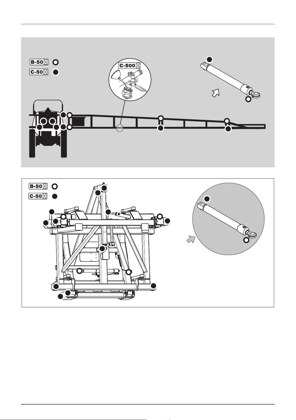
Boom lubrication and oiling plan (32-36 m)
6 - Maintenance
83
Page 84

6 - Maintenance
Trailer/ParaLift lubrication & oiling plan
The lift is remote lubricated from the inside of the trailer’s rear end.
1. Suspended axle attach point.
2. Suspension cylinder attach point.
3. Upper lift arm attach point.
4. Lift cylinder attach point.
5. Lower lift arm attach point.
NOTE! Position 1 and 2 are for suspended sprayers only.
÷
84
Page 85

Service and maintenance intervals
10 hours service - Cyclone Filter
To service the Cyclone filter
1. Turn the pressure SmartValve towards the unused function or to
tank cleaning nozzles.
2. Unscrew filter lid (A).
3. Lift the lid and filter (B) from housing.
4. Turn the two locks (C) outwards to unlock the filter from the lid.
5. Separate filter from the integrated filter guide in the lid and clean
the filter.
To reassemble
1. Grease the two O-rings on the lid/filter guide. Due to small space
at lid for example use a brush to grease with.
2. Mount the filter onto the recess (which may not be greased) in the
lid/filter guide.
3. Turn the two locks (C) inwards to lock the filter to the lid.
6 - Maintenance
4. Place the filter/filter lid into housing and screw the lid until it hits the stop.
WARNING! Always wear protective clothing and gloves before opening the filter!
±
DANGER! The pressure SmartValve must always be turned to the unused function or to tank cleaning nozzles before
€
opening the Cyclone filter! If not then spraying liquid can hit you when opening the filter and drain the main tank
content!
10 hours service - EasyClean filter
This filter has a clogging indicator as mentioned in the “Description”
chapter, but even if this indicator does not show clogging it should
mostly be cleaned every 10 hours.
To service filter
1. Turn the filter lid counter clockwise to open.
2. Remove lid and filter from filter housing.
3. Separate filter element from lid/filter guide.
4. Clean filter and if necessary clean the housing for larger impurities.
To reassemble
1. Grease the O-ring on the filter lid.
2. Press the filter onto filter guide/lid and be sure it has cached the
guides.
3. Reassemble filter/filter lid into housing and be sure it has cached
the guides in the bottom of housing.
4. Turn filter lid clockwise to close lid.
WARNING! Always wear protective clothing and gloves before opening the filter!
±
ATTENTION! If difficulties with opening the filter occur, then it can be emergency handled. See “Emergency operation
- EasyClean filter” on page 112.
85
Page 86
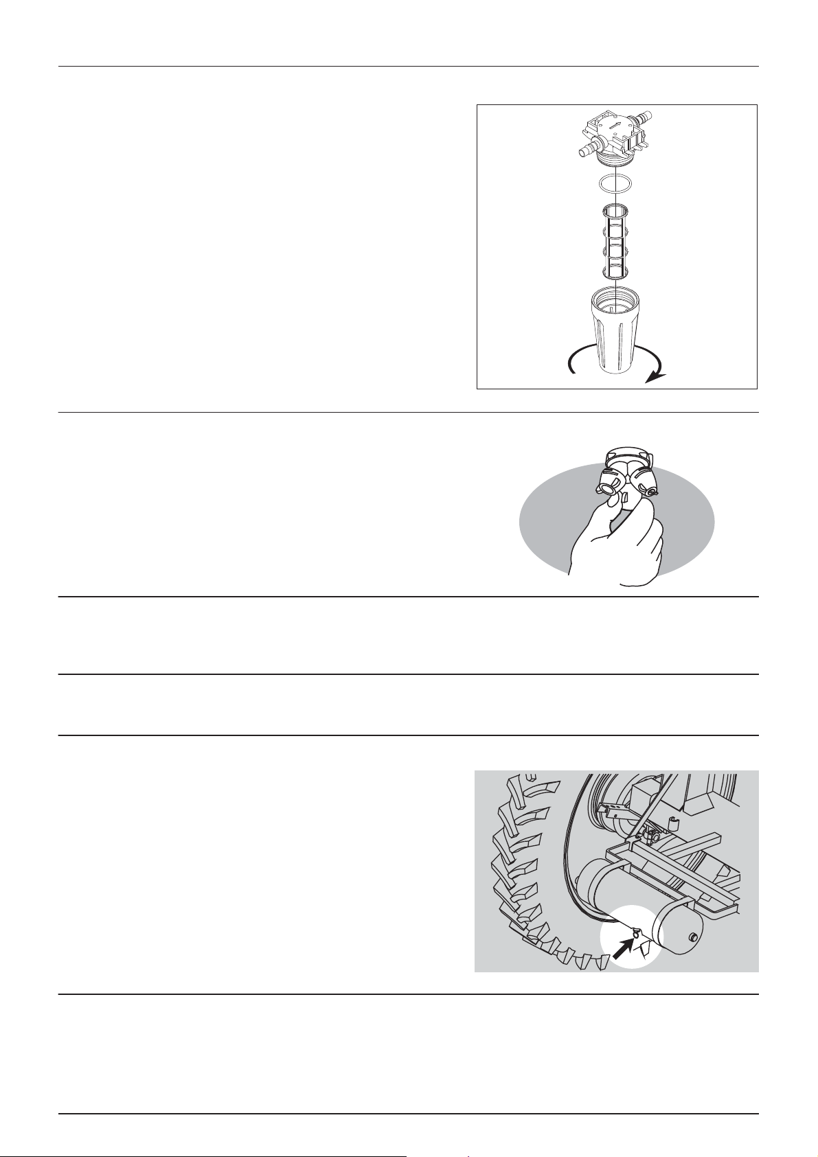
6 - Maintenance
10 hours service - In-Line filter (not PrimeFlow)
If the boom is equipped with In-Line Filters, unscrew the filter bowl to
inspect and clean the filter. When reassembling, the O-ring should be
greased.
Alternative filter meshes are available. See section on Technical
specifications - Filters and nozzles.
WARNING! Be careful not to splash out liquid when unscrewing
±
the filter bowl.
WARNING! Always wear protective clothing and gloves before
±
opening the filter!
10 hours service - Nozzle filters
Check and clean.
10 hours service - Spraying circuit
Fill with clean water, operate all functions and check for leaks using higher spray pressure than normal. Check nozzle spray
patterns visually using clean water.
10 hours service - Brakes (Standard for CM 5500 and 7000)
Apply brake pedal and check function of trailer brakes.
10 hours service - Brakes air tank (optional)
Drain the air tank for condensed water at the drain valve.
10 hours service - Lubricate boom and centre
Some lubrication points on the boom and centre parts need extra attention when having AutoTerrain system. These
lubrication points, marked “10h” in “Boom lubrication and oiling plan” on page 82, need attention every 10 working hours
to work correctly.
86
Page 87

6 - Maintenance
10 hours service - Hydraulic oil level
Check that the oil level is between min. and max. on the sight glass. Clean the area areound the filling cap carefully and add
fresh, clean oil if the level is low. Regarding oil quality - see section the section “Lubricants”.
10 hours service - Gearbox oil level
Check the gearbox oil level is reaching the sight glass. Clean the area areound the filling plug and add fresh, clean oil if the
level is low. Regarding oil quality - see the section “Lubricants”.
50 hours service - Transmission shaft
Check function and condition of the transmission shaft protection guard. Replace any damaged parts.
50 hours service - Wheel nuts
Tighten wheel nuts as follows with following torque wrench settings:
Wheel hub to rim plate: 490 Nm (362 lbft)
Tightening sequence: See illustration and tighten in order of
numbering.
ATTENTION! Some wheel configurations has 10 wheel bolts.
Cross-tighten the same way!
ATTENTION! When wheels has been mounted or re-tightened,
the plastic nut covers must be placed on the nuts afterwards.
50 hours service - Air brakes (optional)
The air brakes are checked for leaks by following procedure:
1. Connect the snap couplers to the tractor and fill the trailer air tanks.
2. Check for leaks with brakes released.
3. Apply the brake up to full pressure.
4. Check for leaks with brakes applied.
50 hours service - Tyre pressure
Check the tyre pressure according to the table in “Technical specifications”.
DANGER! Never inflate tyres more than to the pressure specified in the table. Over-inflated tyres can explode and
€
cause severe personal injuries! See the part “Occasional maintenance - Change of tyre”.
WARNING! If renewing tyres always use tyres with min. load index as specified.
±
87
Page 88

6 - Maintenance
50 hours service - Gearbox bolts
Check/retighten the two gearbox mounting bolts to the specified
torque of 100 Nm (74 lbft).
100 hours service - Check/tighten steering
If too much play is found in the steering section it must be re-tightened.
This applies to both steering and non-steering versions. Re-tighten the
nuts on both sides to the specified torque.
NOTE! Specified torque is 250 Nm.
÷
Be sure that the split pin is fitted (or re-fitted if dismounted) at the end
of the big bolts.
88
Page 89

250 hours service - Readjustment of the boom
See section “Occasional maintenance” on page 93.
250 hours service - Wheel bearings
Check for play in the wheel bearings:
1. Place stop wedges in front of and behind LH wheel and jack up RH
wheel.
2. Rock the RH wheel to discover possible play in the bearings.
3. If any play, support the wheel axle to prevent the trailer from falling
down from the jack.
4. Remove hub cap (A) and cotter pin (B). Turn the wheel and tighten
the castellated nut (C) until a slight resistance in the wheel rotation
is felt.
5. Loosen the castellated nut until the first notch - horizontal or
vertical - is aligned with the cotter pin hole in the shaft.
6. Fit a new cotter pin and bend it.
7. Fit the hub cap to the hub again.
6 - Maintenance
8. Repeat the procedure on LH wheel.
NOTE! Some hub caps are attached with screws. Make sure the seal is intact or replace if worn!
÷
250 hours service - Hydraulic circuit
Check the hydraulic circuit for leaks and repair if any.
Refill Nitrogen accumulators for:
• ParaLift
• Yaw system
• Suspension (if fitted)
WARNING! Hoses for boom lifting device must be changed after every 5 years of use.
±
WARNING! Nitrogen accumulators may contain oil under pressure.
±
250 hours service - Hoses and tubes
Check all hoses and tubes for possible damage and proper attachment. Renew damaged hoses or tubes.
89
Page 90

6 - Maintenance
250 hours service - Inspect parking brake (optional)
Inspect the following:
Parking brake lever
If it can be pulled further backwards than 90° (midway), using a traction
of approximate 25 kg., the cable needs to be adjusted.
Parking brake cable
Inspect the parking brake cables for possible wear or damages. Replace
worn or damaged parts.
When the parking brake is relieved, the cable must be limp; otherwise it
needs to be adjusted.
Correct length:
• When the brake is relieved the cable must be tight and yet not stretched.
• Lengthening/shortening of the parking brake cable is carried out by adjusting the turnbuckle located inside the
chassis.
250 hours service - Air brake filters (optional)
1. Clean the area around air filter(s) and disconnect air hose from the
tractor.
2. Hold one hand under the filter housing, and pull out the retainer
clip (A). The filter cartridge assembly will be pushed out by the
springs inside the filter housing.
3. Clean the filter cartridge. Use water and an appropriate detergent
or compressed air.
4. Dry the parts and reinstall in the order shown. The O-ring should
be lightly lubricated with silicone grease before installation.
WARNING! Never dismantle the filter without having the tractor
±
disconnected and pressure relieved.
250 hours service - Brake adjustment (optional)
Lift the back of the sprayer from the ground. It is recommended to use
two lifting jacks, placed underneath the axle. Make sure the sprayer is
stable and secured before carrying out any adjustments.
1. Loosen the 4 bolts at the brake connector (C) between the brake
arms. Also loosen the screw in each end of the brake connector
and the hand brake cable.
2. Adjust the nut (A) counterclockwise. Turn the nut 60° (1/6 turn) at
a time - alternately on both LH and RH brake. Continue adjustment
till resistance occurs when rotating the hub/wheel.
3. Turn the nut 60° (1/6 turn) clockwise to loosen brake. Hub/wheel should rotate freely now.
4. Tighten the brake connector (C) bolts again.
5. Tighten the hand brake cable again - See “250 hours service - Inspect parking brake (optional)” on page 90.
WARNING! The adjustment must be carried out simultaneously on both brakes. Therefore, alternately adjust on both
±
LH brake and RH brake.
90
Page 91
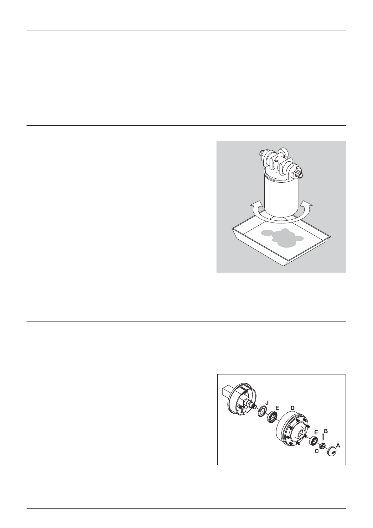
6 - Maintenance
250 hours service - Hydraulic brakes (optional)
Apply brakes to full pressure and inspect brake lines for damages or leaks. Replace damaged parts. If the hydraulic brake lines
have been dismantled the circuit must be primed afterwards:
1. Loosen brake hose at both brake cylinders.
2. Apply brake until oil without air bubbles come out.
3. Tighten brake hose before relieving the brake again.
WARNING! Always prime the circuit if the hydraulic brake lines have been dismantled.
±
500 hours service - Hydraulic oil filter
Change the hydraulic oil filter after the first 50 hours and then every 500
hours or once a year - whichever comes first.
Always change the oil filter if the vacuum meter indicator is in the red
area. Check when the oil has reached working temperature.
1. Place e.g. a drain pan or a cloth under the filter to retain waste oil
and unscrew the filter cartridge.
2. The new filter cartridge is filled with fresh clean hydraulic oil. Apply
a thin oil film to the cartridge seal.
3. Screw the filter cartridge on until the seal is lying against the
flange.
4. Tighten the filter cartridge another 1/2 to 3/4 turn.
5. Check hydraulic oil level - top up with fresh clean hydraulic oil if
necessary.
6. Set the blower in neutral, start the tractor P.T.O. and let it run idle
for 5 min. to prime the system.
7. After 5 min. the blower r.p.m. can gradually be increased to full speed.
ATTENTION! Disposal of used hydraulic filter cartridges must only take place in accordance with local legislation.
1000 hours service - Wheel bearings and brakes
Check the condition of the bearings and brake wear parts in the following way:
WARNING! If you do not feel totally confident changing wheel bearings or brake shoes contact your HARDI dealers
±
workshop.
1. Place stop wedges in front of and behind the opposite wheel to
the one to be serviced (e.g. LH wheel). Jack up the wheel to be
serviced (e.g. RH wheel).
2. Support the trailer with axle stands.
3. Remove the wheel.
4. Unscrew the 6 Allen bolts and remove the hub cap (A), cotter pin
(B) and castle nut (C).
5. Pull off the brake drum (D). Use a wheel puller if necessary.
6. Vacuum clean the brake drum (D) for brake dust or rinse with
water.
DANGER! Brake dust can cause severe health injuries! Avoid inhalation of brake dust! Use respirator when servicing
€
the brakes. Do not clean brakes with compressed air! Use vacuum cleaner or rinse with water to avoid brake dust
being blown around.
91
Page 92

6 - Maintenance
7. Rinse the remaining parts on the brake carrier plate with water and dry them.
8. Remove roller bearings (E), clean all parts in degrease detergent and dry them.
9. Check the brake drum diameter and lining thickness - renew if worn.
WARNING! The specified min. thickness is the absolute minimum which must never be exceeded. Renew the parts if
±
they would reach the above dimensions before next service inspection.
WARNING! Renewal of brake linings or brake drums must be done both sides at the same time.
±
ATTENTION! If the brake drum must be removed from the wheel hub, a hydraulic press is required to press the wheel
studs out.
10. Remove the clevis pin between the air diaphragm cylinder and
brake cam lever.
11. Remove the cotter pin (G) and castle nut (F), the brake shoe anchor
bolt (H) and slide the brake shoes over the cam. Twist the pair of
brake shoes to remove the shoe return springs (I). Replace brake
shoes if the linings are worn.
12. Apply a small quantity of copper paste on moving parts and
assemble the brake shoes and shoe return springs (I) again.
WARNING! Do not get copper paste in contact with the brake
±
linings and drums.
13. Fit the shoe assembly with the anchor bolt (H) first. Then pull the
shoes away from each other and slide them over the cam
afterwards. Tighten the anchor bolt castle nut (F) again and fit a
new cotter pin (G).
14. Check roller bearings for discolouration and wear - renew if worn
or damaged.
15. Assemble drum (D) and bearings (E) using a new sealing ring (J).
16. Fill the hub and bearings with fresh grease before fitting it to the shaft.
WARNING! Do not get oil or grease in contact with the brake linings and drums.
±
17. Fit the castle nut (C). Rotate the brake drum (D) and tighten the castle nut (C) until a slight rotation resistance is felt.
18. Loosen the castle nut (C) again until the first notch is aligned with the cotter pin hole in the shaft.
ATTENTION! The shaft has a vertical and an horizontal cotter pin hole. Use the one first aligned with the notch when
loosening the castle nut.
19. Fit a new cotter pin (B) and bend it.
20. Fit the hub cap (A) to the hub. Slightly tighten the 6 Allen bolts.
21. Adjust the brakes as described in “250 hours service - Brake adjustment (optional)” on page 90.
22. Fit the wheel again and tighten the wheel nuts. See “50 hours service - Wheel nuts” on page 87 regarding torque
wrench setting. Tighten all bolts to half the specified torque first, then to the full specified torque.
23. Tighten again after 10 hours of work. Check the torque every day until it is stabilized.
92
Page 93

6 - Maintenance
Occasional maintenance
General info
The maintenance and renewal intervals for the following will depend very much on the conditions under which the sprayer
will be operated and are therefore impossible to specify.
Pump valves and diaphragms renewal
Model 463 pump:
Diaphragm pump overhaul kit (valves, seals, diaphragms etc.) can be
ordered. Detect the pump model - kit can be ordered at following
HARDI part No.:
Model 463: part No. 75073900
Valves
Remove valve cover (1) before changing the valves (2) - note their
orientation so they are replaced correctly!
ATTENTION! A special valve with white flap (2A) is used at the two
upper side inlets. It has to be placed in the valve openings as
shown. All others are the type with black flap. It is recommended
to use new gaskets (3) when changing or checking the valves.
Diaphragms
Remove the diaphragm cover (4). The diaphragm (5) may then be
changed. If fluids have reached the crankcase, re-grease the pump
thoroughly. Also check that the drain hole at the bottom of the pump is
not blocked. Reassemble with the following torque setting.
Reassemble pump model 463 with the following torque setting.
Diaphragm cover: 90 Nm / 66.6 lbft
Diaphragm bolt: 90 Nm / 66.6 lbft
ATTENTION! Before tightening the 4 bolts for the diaphragm cover (B) the diaphragm must be positioned between
centre and top to ensure correct sealing between diaphragm pump housing and diaphragm cover. Turn crank shaft
if necessary.
93
Page 94

6 - Maintenance
Level indicator wire renewal
If the wire on the level indicator has to be changed, the float guide pole is removed:
1. Remove the tank drain valve (see paragraph “Drain valve seal renewal”) and loosen the fitting holding the pole in
position.
2. Pull the pole down through the drain valve hole till it is free in the top of the tank.
3. The pole can now be taken out of the tank through the filling hole.
DANGER! Do not enter the inside of the tank - the parts can be changed from the outside of the tank!
€
Level indicator adjustment
The level indicator reading should be checked regularly. When the tank
is empty, the float should lie on the stop pin (D) of the rod, and the Oring on the indicator should be positioned at the top position line (A).
ATTENTION! The wire guide wheels should be directed so they
follow the direction of the wire.
If any deviation is found, do:
1. Pull out the plug (B).
2. Loosen screws (C).
3. Adjust the length of the cord until it reads correctly.
4. Push plug (B) back in place.
NOTE! For best accuracy adjustment shall be done with the
÷
sprayer attached to the tractor normally used.
Drain valve seal renewal
If the main tank drain valve leaks, the seal and seat can be changed the
following way.
DANGER! Do not enter the inside of the tank - the parts can be
€
changed from the outside of the tank!
WARNING! Use eye / face protection mask when dismantling the
±
tank drain valve!
1. Make sure the tank is empty and clean.
2. The valve must be closed and the string loose.
3. Pull out the clip (A) and pull down connecting piece (B). The entire
valve assembly can now be pulled out.
4. Check cord and valve flap assembly (C) for wear, replace seal (D)
and assemble again.
5. Assemble the valve assembly again using a new valve seat (E). Lubricate O-rings (F) before assembly.
6. Fit clip (A) again.
ATTENTION! Check function of valve with clean water before filling chemicals into the tank.
94
Page 95

Adjustment of 3-way valve
The large ball valve (s93) used for SmartValves and valves for filling
equipment can be adjusted if it is too tight to operate - or if it is too loose
(=liquid leakage).
• Correct setting is when the valve can be operated smoothly by one
hand.
Use a suitable tool and adjust the toothed ring inside the valve as shown
on the drawing.
ATTENTION! The small ball valves (s67) cannot be adjusted.
Feed pipe snap-lock assembly
Disassembly
1. Screw the union nut (A) completely off.
2. Pull the feed piping and hose barb apart.
6 - Maintenance
3. Take out the O-ring (B).
4. Inspect and oil O-ring (B). Change the O-ring (B) if worn, before
reassembly.
Reassembly
1. Check that the barbed lock ring (C) is fitted to the feed pipe with
barb pointing away from pipe opening.
2. Fit the oiled O-ring (B) on top of the lock ring (C).
3. Push the feed pipe and hose barb together.
4. Screw the union nut (A) on the hose barb and tighten union nut
(A) by hand.
Initial fitting of fittings
ATTENTION! This method can only be used for pipes not fitted
into pipe clamps.
1. Fit the barbed lock ring (C) to the feed pipe with barb pointing
away from pipe opening.
2. Fit the oiled O-ring (B) on top of the lock ring.
3. Screw the union nut (A) partly on the hose barb.
4. Press the feed pipe and hose barb together.
5. Tighten the union nut (A) by hand.
95
Page 96

6 - Maintenance
Feed pipe clamp assembly
A feed pipe can be removed from the pipe clamps the following way:
1. Use a flat bladed screwdriver to prize the cover off the first corner
(A).
2. Hold the clamp top with your hand and prize off the opposite
corner (B) with the screwdriver.
3. Prize off the other side of the pipe clamp with the screwdriver.
4. Take out the feed pipe.
Opening the cable trays
The cable trays on the boom can be opened for servicing or re-wiring.
Disassembly
1. Use a screwdriver at the end of a cable tray to prize the cable tray cover off the lock hooks.
2. Pull the cable tray cover off.
Assembly
1. Press the cover on by hand until it hits the hooks of the cable tray.
96
Page 97

Readjustment boom - general info
Before commencing adjustment jobs please go through this check list.
1. The sprayer must be well lubricated (see section about lubrication).
2. Connect the sprayer to the tractor.
3. Place tractor and sprayer on level ground (horizontal).
4. Unfold boom.
5. Set slanting angle to neutral position (horizontal).
ATTENTION! For information on boom terminology see “Boom and terminology” on page 28.
NOTE! Adjustment of hydraulic cylinders is to be carried out without pressure in the system.
÷
WARNING! Nobody is allowed to be under the boom whilst adjustment is carried out.
±
Alignment of centre and inner wing sections
The boom tip must point slightly forward. If necessary adjust the inner
section folding as follows:
6 - Maintenance
1. Depressurize the folding rams.
2. Loosen counter nut (A).
3. Adjust stop screw (B) until the correct setting is reached.
4. Tighten counter nuts again.
97
Page 98

6 - Maintenance
Alignment of inner and 1st outer wing sections
The outer sections must be aligned with the inner wing sections. If
necessary adjust the outer wing sections as follows:
1. Depressurize the folding cylinders.
2. Loosen counter nuts (A) and (C).
3. Loosen the screws (B).
4. Adjust the rigging screw (D) until the correct setting is reached.
Adjust the stop screws (B) up against the inner section.
5. Tighten counter nuts again.
6. Check the alignment. If needed, redo the adjustment described
above.
ATTENTION! The rigging screw (D) must be slightly ‘over’
tightened/adjusted to insure a firm and fixed outer section.
Alignment of inner and 1st outer wing sections (32-36 m)
The outer sections must be aligned with the inner wing sections. If
necessary adjust the outer wing sections as follows when unfolded:
1. Depressurize the folding cylinders.
2. Loosen counter nut (A).
3. Loosen the screws (B).
4. Adjust the rigging screw (D) until the correct setting is reached.
Some 10 mm blank on the cylinder should be visible.
5. Adjust the stop screws (B) up against the inner section.
6. Tighten counter nuts again.
7. Check the alignment. If needed, redo the adjustment described
above.
Breakaway section adjustment
The breakaway section must release when a force of approximately 150
N is applied to the extremity of the breakaway section. If necessary, the
release force is adjusted as follows:
1. Make sure that claw coupling is correctly lubricated.
2. Loosen the counter nut (A).
3. Adjust the nut (B) until the breakaway will release at a force of 150
N applied at the extremity of the section.
4. Tighten the counter nut again.
DANGER! Never place fingers into open breakaway clutch! You
€
may be injured if clutch snap closed accidentally!
WARNING! Do not tighten the breakaway clutch more than what
±
is necessary. Over tightening can cause damage to the boom.
98
Page 99

Breakaway section adjustment (32-36m)
The breakaway section must release when a force of approximately 150
N is applied to the extremity of the breakaway section. If necessary, the
release force is adjusted as follows:
1. Make sure that claw coupling is correctly lubricated.
2. Loosen the counter nut (A).
3. Adjust the nut (B) until the breakaway will release at a force of 150
N applied at the extremity of the section.
4. Tighten the counter nut again.
DANGER! Never place fingers into open breakaway clutch! You
€
may be injured if clutch snap closed accidentally!
WARNING! Do not tighten the breakaway clutch more than what
±
is necessary. Over tightening can cause damage to the boom.
Hydraulic slanting control adjustment
6 - Maintenance
Alignment of neutral position for the entire boom.
1. Place tractor and sprayer on even, flat ground.
2. Unfold the boom.
3. Slanting cylinder: Expose piston rod (A) 90 mm.
4. Adjust hinge ring (B) in/out till boom is horizontal.
Hydraulic slanting control adjustment (32-36m)
Alignment of neutral position for the entire boom.
1. Place tractor and sprayer on even, flat ground.
2. Unfold the boom.
3. Slanting cylinder: Expose piston rod (A) 90 mm.
4. Adjust hinge ring (B) in/out till boom is horizontal.
99
Page 100
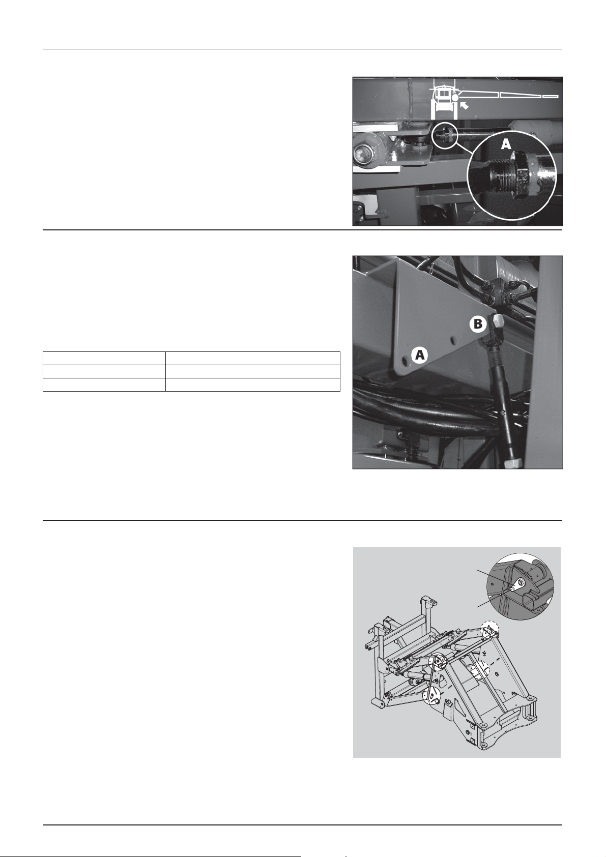
6 - Maintenance
A
B
Wing tilt adjustment
The horizontal adjustment of the wings is done by the retracted tilt
cylinder. The boom must be straight and horizontal. If necessary, adjust
the wing as follows:
1. Support the boom to relieve the load from the hydraulic cylinder.
2. Loosen counter nut (A), which is positioned by the hinge ring on
the cylinder’s piston rod.
3. With a wrench (two flattened spots on end of the ram) adjust the
cylinder ram inwards or outwards to get the desired wing level.
4. Repeat steps for other side.
Spring arrangement (32-36 m only)
The adjustable spring arrangement on centre section straightens abrupt
boom movements. If different field conditions appears, the
arrangement may need adjustment.
The force of the straightening effect can be adjusted by tightness and
position of springs.
On the upper berth plate there are 3 positions for the springs:
Hole closest to centre (B) Less straightening of boom.
Middle hole Medium straightening of boom
Hole farthest away from centre (A) Powerful straightening effect will be obtained.
To mo v e pos i t ion
1. Loosen the rigging screws.
2. Dismount upper bolt and move arrangement to the selected eye.
3. Refit bolt and tighten rigging screw. The rigging screw should be
tightened so much that there is no slope in it, but the spring
should not be stretched out either. Tighten so both springs have
same tightness when boom is lever.
Wear bushing renewal on boom lift
Inspect and replace the wear bushes before they are worn through.
1. Connect the trailer to a tractor and unfold the booms to working
position.
2. Lift the boom centre frame with a lifting device and support it until
the load is taken off the parallelogram arms.
3. Remove the screws (A), pull out the pins (B) at one of the upper
parallelogram arms and replace the wear bushes.
4. Refit the arm.
5. Repeat this on the other upper arm.
6. The lower arms must be disconnected simultaneously.
7. Grease all grease nipples.
8. Remove the lifting gear again.
100
 Loading...