

Page 1
COMMANDER
Operator’s Manual
67020003 (6/02)
Page 2

Page 3
HARDI
COMMANDER
Operator’s Manual
67020003 (6/02)
HARDI® reserves the right to make changes in design,
material, or specification without notice thereof.
®
and other product names are registered trademarks
HARDI
of HARDI
®
Inc. in the U.S. and in other countries.
Page 4

Table of Contents
Introduction ................................................................4
COMMANDER Plus ..............................................5
Description ................................................................. 6
Frame.................................................................... 6
Tank ...................................................................... 6
Pump..................................................................... 6
MANIFOLD system ...............................................6
Operating unit .......................................................6
Filters ....................................................................6
Paralift™ ...............................................................6
Booms ...................................................................6
Boom hydraulics ...................................................6
Identification plates ............................................... 6
Sprayer use ................................................................ 7
Unloading the sprayer from the truck ..................... 7
Before putting the sprayer into operation .............. 7
Safety Instructions .................................................... 8
Operating The Sprayer Safely ..............................8
Handling Chemical Products Safely .....................9
Local Poison Information Center ..........................9
Connecting the sprayer........................................... 10
Drawbars ............................................................ 10
Mounting the drawbar hitch ................................10
Drawbar hitch height adjustment ........................ 10
Support jack ........................................................10
Fixed drawbar adjustment .................................. 11
Steering drawbar (optional) ................................ 11
Hose package support........................................ 11
P.T.O. Shaft............................................................... 12
P. T.O. Shaft Operator Safety ..............................12
Installation of P.T.O. Shaft ..................................12
Wheel tread adjustments ........................................ 13
Altering the wheel track width.............................13
Axle Systems & Tire Assemblies ...........................14
Hydraulic system .....................................................15
Hydraulics - standard joystick handle .................15
Direct Acting Hydraulic system (D.H.) ................16
Control boxes and power supply ........................16
Transport .................................................................. 17
Roadworthiness ..................................................17
Rear lights........................................................... 17
Transport brackets, height setting ......................17
Transport lock .....................................................17
Transport lock arm stop ...................................... 18
Adjusting boom transport position ......................18
Driving Technique ................................................... 19
Steering Drawbar (optional)................................ 19
Disconnecting the sprayer...................................... 20
Support leg ......................................................... 20
P. T.O. shaft support ............................................ 20
Operating the boom ................................................. 21
Unfolding and folding the HZ EAGLE™ boom ...21
Unfolding and folding the HZ FORCE™ boom .. 22
Tilting the HZ FORCE™ boom ...........................23
ECP Plumbing Diagram ........................................... 24
Operating the liquid system ................................... 25
MANIFOLD SYSTEM ......................................... 25
Use of MANIFOLD valve system ........................25
Electrical operated MANIFOLD valves (opt.) ..... 26
Filling the tanks on the COMMANDER Plus ......... 26
Filling main tank through tank lid ........................ 26
Filling flush tank (optional) through lid................26
Filling with external Quick Fill (optional) ............. 27
Filling of clean water tank ...................................27
Adjustment of ECP operating unit .........................28
Adjustment of constant pressure ........................ 28
Operating the control unit while spraying ...........28
Remote 4” pressure gauge ..................................... 29
Self cleaning filters .................................................. 29
Choice of correct restrictor for S.C.F. ................. 29
Adjustment of Air Pressure in Pressure Damper
(1302 Pump Only) .................................................... 29
Filling of chemicals ................................................. 30
Filling through tank lid......................................... 30
Filling with HARDI
Operating with Liquid-based chemicals.............. 30
Operating with Powder-base chemicals .............31
Use of flush tank and rinse nozzles (optional) .....32
Technical Residue ................................................... 32
Draining tanks .......................................................... 32
Main tank drain valve.......................................... 32
Flush tank (optional) ...........................................32
Foam marker tank (optional) .............................. 32
Nozzle Selection ...................................................... 33
Calibration ................................................................ 35
Maintenance - rules of thumb .................................36
Cleaning the sprayer ..........................................36
Cleaning the tank ................................................37
Cleaning and maintenance of filters ...................37
Lubrication ............................................................... 38
About lubricants .................................................. 38
Recommended lubricants ................................... 38
Lubrication schedule........................................... 39
Service and Maintenance intervals ........................ 42
10 hours service ................................................. 42
50 hours service ................................................. 42
100 hours service ............................................... 42
250 hours service ............................................... 42
1000 hours service or yearly .............................. 42
Occasional maintenance .................................... 43
Off-season storage ..................................................50
Preparation after off season storage ..................50
Equipment and Accessories .................................. 51
Troubleshooting ...................................................... 55
Emergency operation of the sprayer .....................60
Technical specifications ......................................... 61
Overall measurements ....................................... 61
Weight .................................................................61
Filters and nozzles ..............................................62
Temperature and pressure ranges ..................... 62
Electrical connections - Rear lights ....................62
Electrical connections for ECP operating unit ....62
Installation instruction for boom and work light ..63
EAGLE™ and FORCE™ boom hydraulics ............ 64
Warranty Policy and Conditions ............................ 65
®
CHEMICAL FILLER ............ 30
2 HARDI® COMMANDER OPERATOR’S MANUAL
Page 5

Dear Owner,
Thank you for purchasing a HARDI
®
HARDI
sprayer owners.
®
product and welcome to the ever- increasing family of
Our sprayers and accessories are rapidly becoming a familiar sight on North American farms.
We believe that this results from growers becoming increasingly conscious of crop protection
input costs and the vital need for cost effective spray application equipment.
Please take the time to thoroughly read the Operator’s Manual before using your equipment.
You will find many helpful hints as well as important safety and operation information.
Some of the features on your HARDI
®
COMMANDER Plus sprayer were suggested by growers. There is no substitute for “on farm” experience and we invite your comments and suggestions.
Please address your correspondence to the Service Manager at one of these branches:
HARDI® MIDWEST
1500 West 76th St.
Davenport, Iowa 52806
Phone: (563) 386-1730
Fax: (563) 386-1710
HARDI® WEST COAST
5646 W. Barstow, Suite 101
Fresno, California 93722
Phone: (559) 271-3106
Fax: (559) 271-3107
HARDI® GREAT LAKES
290 Sovereign Rd.
London, Ontario N6M 1B3
Phone: (519) 659-2771
Fax: (519) 659-2821
Sincerely,
Tom L. Kinzenbaw
President
3HARDI® COMMANDER OPERATOR’S MANUAL
Page 6
Introduction
We congratulate you for choosing a HARDI® plant protection product. The reliability and efficiency of this product
depends upon your care. The first step is to carefully read and pay attention to this instruction book. It contains
essential information for the efficient use and long life of this quality product.
The COMMANDER Plus 750 and 1200 trailer sprayers consist of a powder coated frame with a tank, diaphragm
pump, ECP control (Electric Control Plus), HARDI
System, and 45’, 50’, 60’ or 66’ EAGLE™ series spray boom. The 1200 trailer sprayers additionally offer 80’, 88’,
90’, or 100’ EAGLE™ series spray boom and 80’, 88’, 90’, 100’, or 120’ FORCE™ series spray boom.
®
Manifold system, Self-Cleaning Filter, Paralift™ Boom Lift
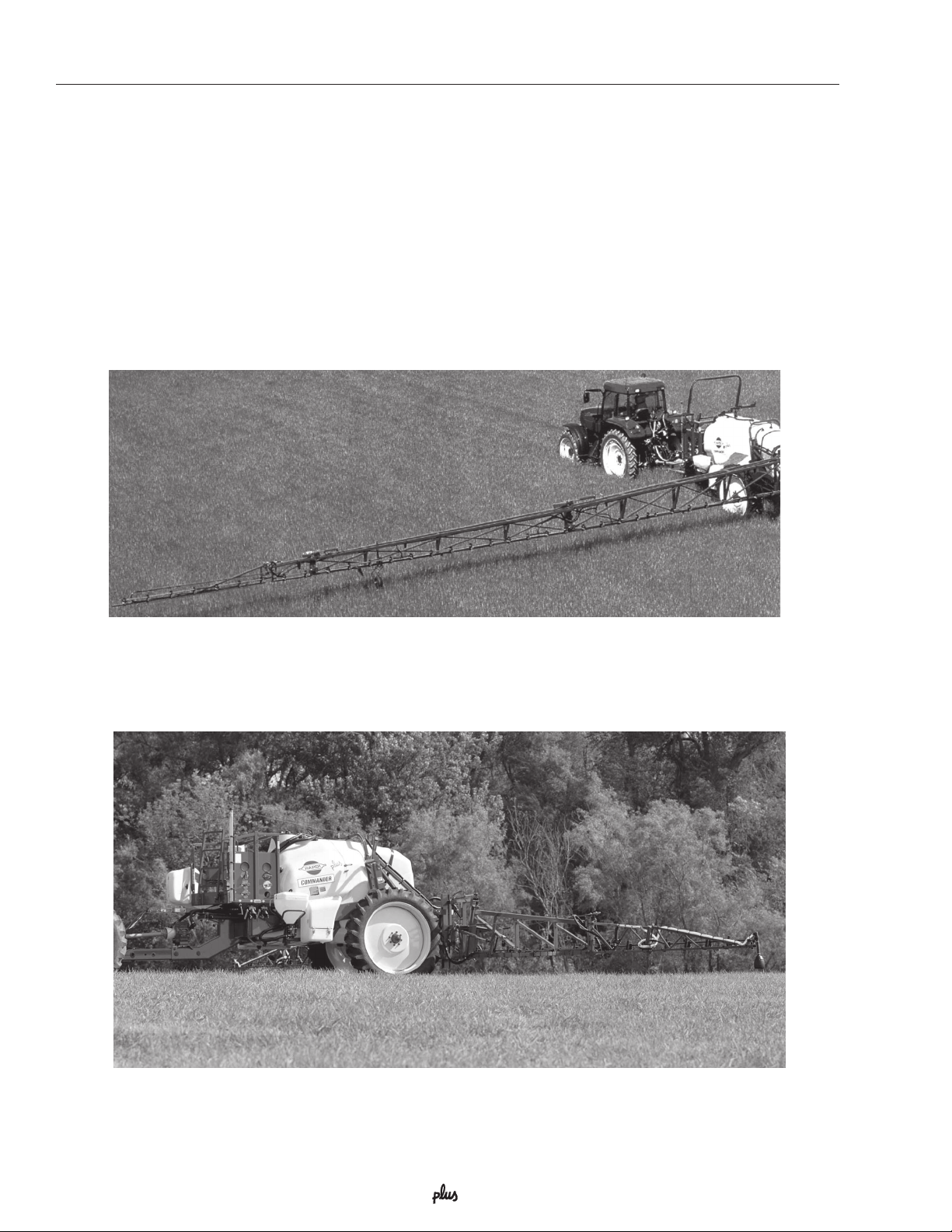
Commander plus 1200 gallon with 120’ Force™ boom
Commander plus 750 gallon with 60’ Eagle™ boom
4 HARDI® COMMANDER OPERATOR’S MANUAL
Page 7
Introduction
COMMANDER Plus
The COMMANDER Plus is divided into three zones: a Clean zone, a Working zone and an Application zone,
referring to the level of possible pesticide contamination.
CLEAN ZONEWORKING ZONEAPPLICATION ZONE
PARALIFT™ boom lift system
Boom
Nozzles
Suspension
*
Please note that some of the features are optional equipment
*
Tank level indicator
MANIFOLD valves
Couplers for Quick Fill
Working platform with
ladder
Hydraulic and electric
components
Boom and Work lights
*
HARDI
*
Lockers for pesticide
*
containers and equipment
®
FILLER
Locker for protective gear
Clean water tank
Tap for hand washing
Support leg
Pump
P. T.O. shaft
5HARDI® COMMANDER OPERATOR’S MANUAL
Page 8
Description
Description
Frame
Strong and compact frame with optional drawbars and
wheel sizes. The frame has a strong chemical and
weather resistant powder coat. Screws, nuts, etc. have
been electrochemically treated to be resistant to
corrosion.
Tank
The tanks, made of impact proof and chemical resistant
polyethylene, have a purposeful design with rounded
contours which allows for efficient cleaning and draining. The tanks are designed with a large deep sump, so
that they can be completely emptied even when the
sprayer is used on slopes up to 15% inclination. A
remote operated valve drain is fitted for efficient draining.
Pump
The HARDI® diaphragm pumps have low maintenance
requirements and guaranteed pump life. The bearings
and crankshaft are grease lubricated and are therefore
protected from spray solution if any diaphragm fails in
service. A drain hole is in the base of the crank case to
facilitate the draining of any foreign matter. The diaphragm pumps are self priming and can be run dry
without damage.
MANIFOLD SYSTEM
All functions of the spray circuits are operated via the
centrally situated MANIFOLD valves with color coded
plates and pictorial symbols for easy operation.
Operating unit
The ECP - Electrical Control Plus is divided into two
sections. The pressure regulation valve is located at
the front of the sprayer. The boom section control
valves with pressure equalization are mounted at the
rear of the sprayer. The on/off switch is linked to the
boom section valves, which results in a very quick
response to on/off operation. The built-in HARDIMATIC mechanical rate controller ensures a constant
volume per acre of the liquid (gpa) at varying forward
speed within the same gear when the number of P.T.O.
revolutions are between 300-600 r.p.m. (540 r.p.m
pump) or 650-1100 r.p.m. (1000 r.p.m. pump).
Paralift™
The Paralift™ boom lift system consists of parallel lift
arms that hydraulically lift and lower the boom assembly, ensuring that the boom remains parallel to the
ground. A locking cylinder and arms are fitted to ensure
that the paralift cylinders are relieved of any hydraulic
pressure when the boom is in the transport position.
Booms
The EAGLE™ SPB boom is available in 45’, 50’, 60’,
and 66’ working width.
The EAGLE™ SPC boom is available in 80’, 88’, 90’
and 100’ working width.
The FORCE™ FTZ boom is available in 80’, 88’, 90’,
100’ and 120’ working widths.
Outer sections incorporate spring loaded breakaways.
Boom hydraulics
The SPB, SPC and FTZ booms are equipped with
I.A.H. (Indirect Acting Hydraulics). Optional D.H. (Direct
Acting Hydraulics) is available.
The boom is operated via the tractor hydraulics. It
features hydraulic lift cylinders for boom height adjustment, boom wing fold and tilt cylinders that give the
ability to obtain individual boom wing tilt as well as
individual boom wing fold.
The hydraulics are controlled via a joystick or via a
hydraulic control box.
Identification plates
An identification plate fitted on the frame indicates
model and serial number. Frame, boom center frame,
and inner/outer sections also have identification plates
indicating boom type and part number of spare parts. If
ordering spare parts, inform your dealer of these, so
the right model and version are described.
Filters
With the self-cleaning filter, the impurities that exist in
the spray liquid will bypass the filter and be recirculated
back to the tank via the return flow. Suction filter and inline pressure filters are standard with all booms.
6 HARDI® COMMANDER OPERATOR’S MANUAL
HARDI
INC
Model
Serial No.
DAVENPORT
IOWA
C+1200
12-0002
Page 9
Description
Sprayer use
The HARDI® COMMANDER Plus sprayer is for the
application of crop protection chemicals and liquid
fertilizers.
If no local law demands that the operator must be
certified to use the spray equipment, it is strongly
recommended to be trained in correct plant protection
and in safe handling of plant protection chemicals to
avoid unnecessary risk for persons and the environment when doing the spray job.
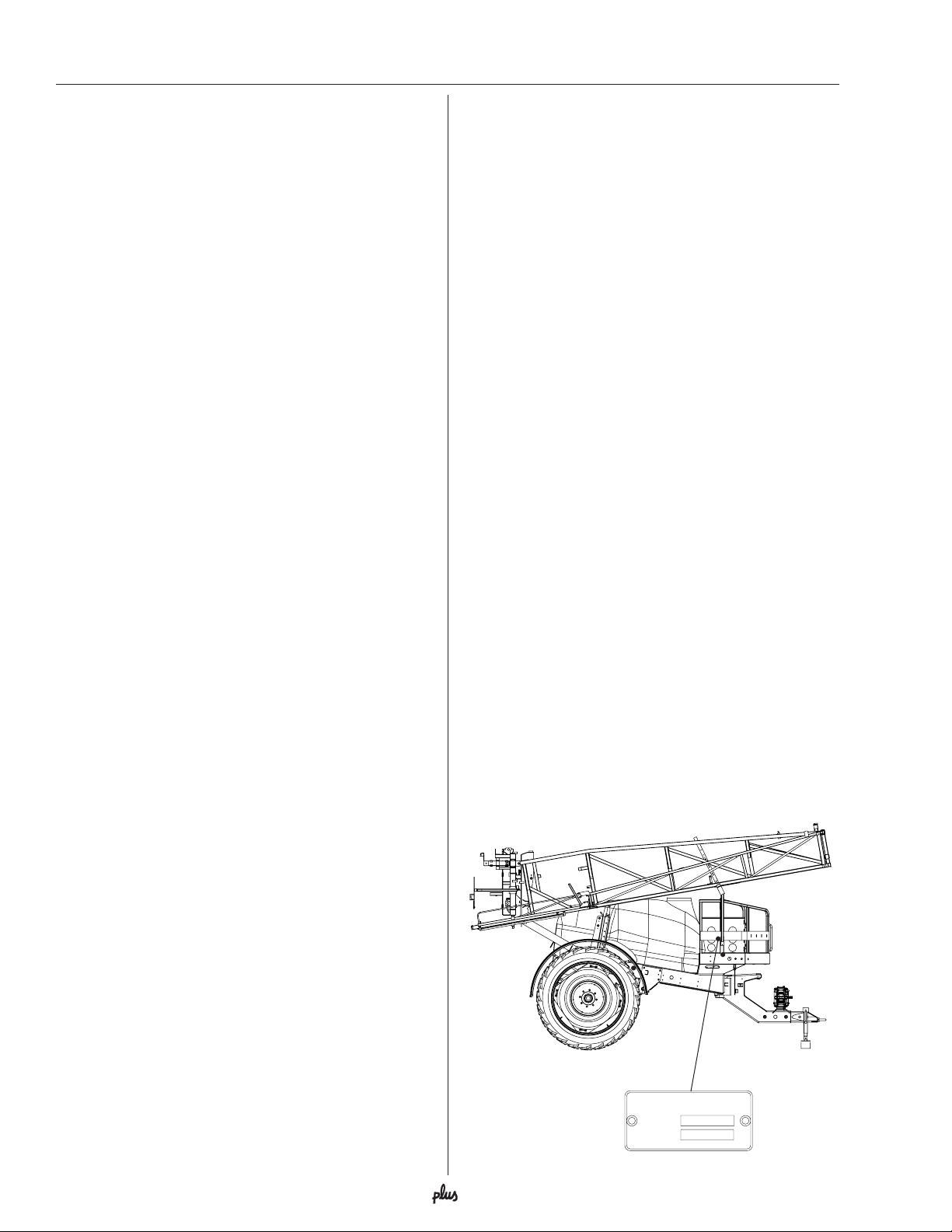
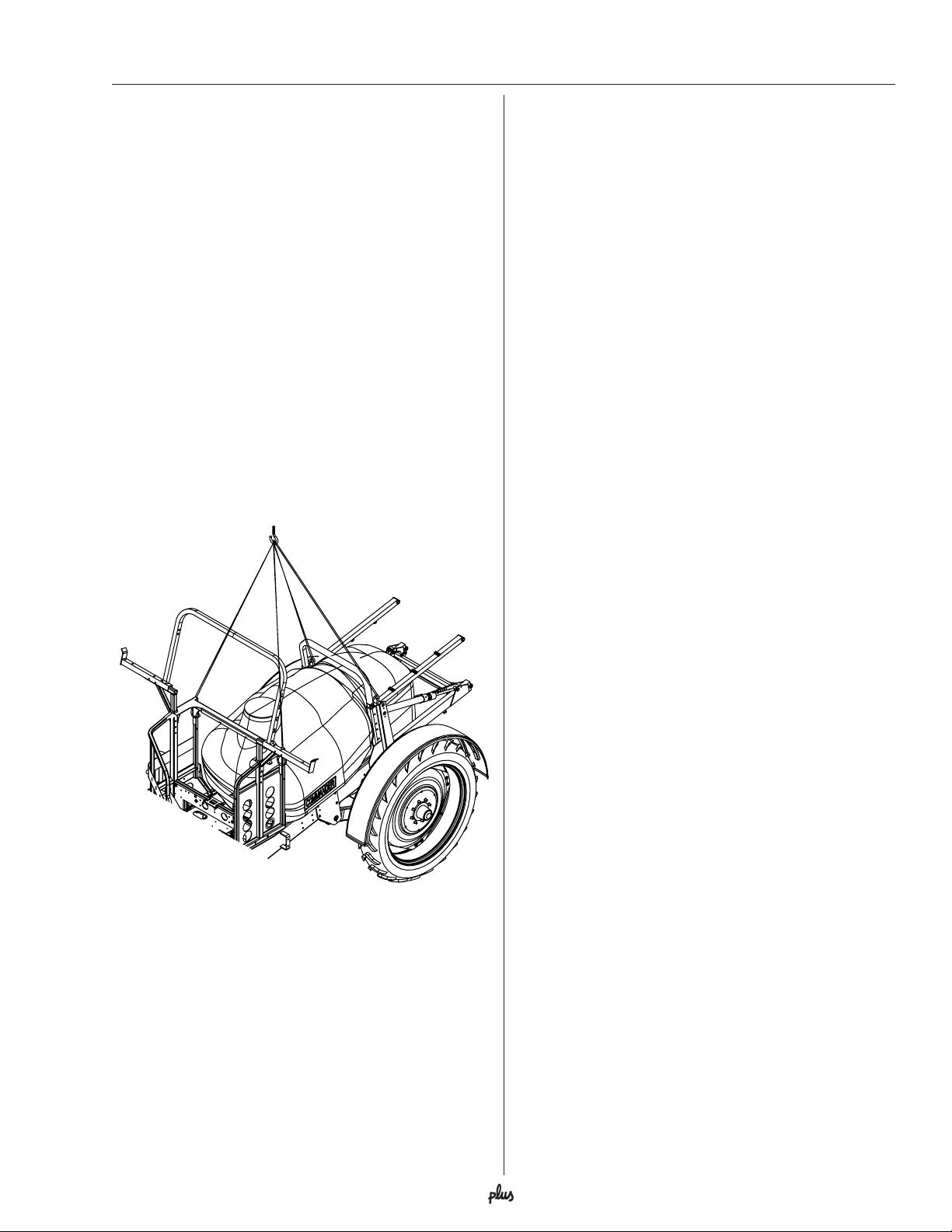
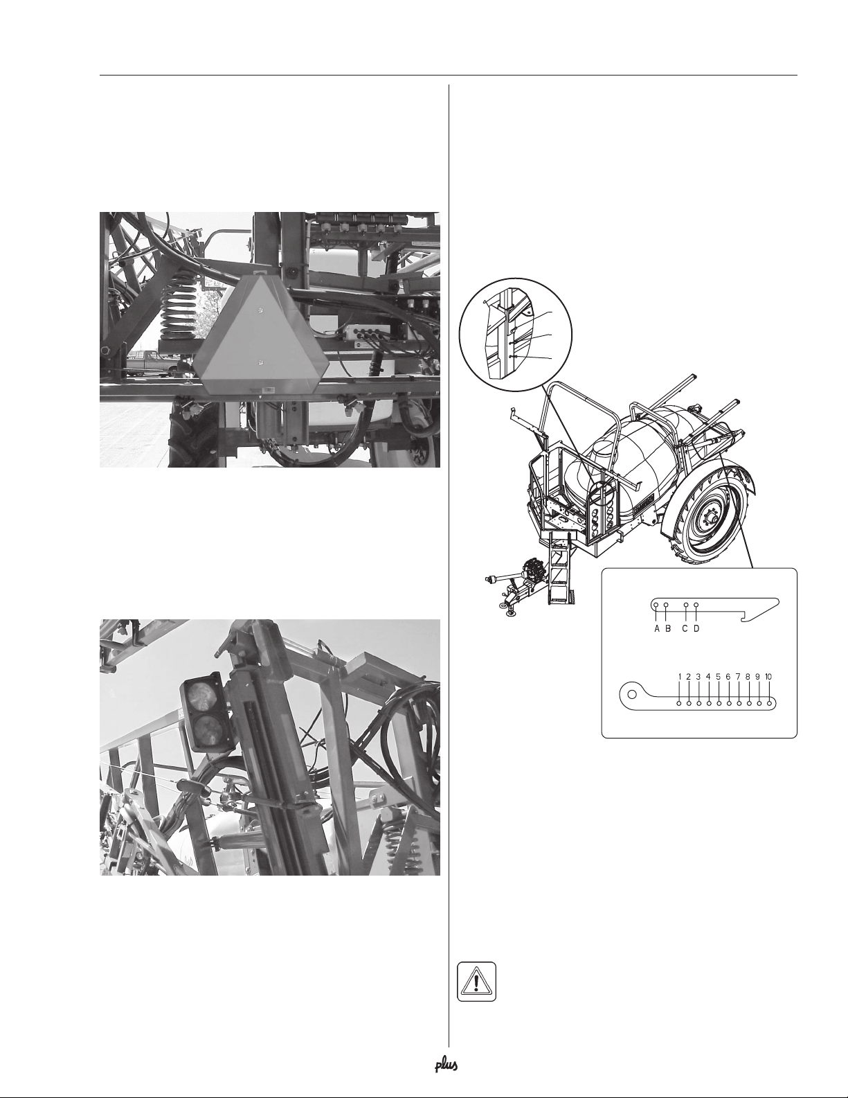
Unloading the sprayer from the truck
When unloading the sprayer, a crane or a fork lift is
needed. When loading with a crane, please observe
the lifting points as shown on the illustration and make
sure that the straps or belts used for lifting are suitable
for the application.
Before putting the sprayer into
operation
Although the sprayer has been applied with a strong
and protective surface treatment on steel parts, bolts
etc. in the factories, it is recommended to apply a film
of anticorrosion oil (e.g. CASTROL RUSTILLO or
SHELL ENSIS FLUID) on all metal parts in order to
avoid chemicals and fertilizers discoloring the enamel.
Avoid oil on rubber parts, hoses and tires.
If this is done before the sprayer is put into operation
for the first time, it will always be easy to clean the
sprayer and keep the enamel shiny for many years.
This treatment should be carried out every time the
protection film is washed off.
7HARDI® COMMANDER OPERATOR’S MANUAL
Page 10

Safety instructions
SAFETY INFORMATION
WARNING
ALWAYS READ OPERATOR’S MANUAL BEFORE
USING EQUIPMENT
DO NOT REMOVE ANY SAFETY DEVICES OR
SHIELDS. NEVER SERVICE, CLEAN OR REPAIR A
MACHINE WHILE IT IS OPERATING
WARNING
• Keep your sprayer in proper working condition.
Unauthorized modifications or use may impair the
function and/or safety and affect the machine’s life.
• If you do not understand any part of this manual and
need assistance, please contact your authorized
HARDI® dealer.
Operating The Sprayer Safely
1. Read the complete manual carefully and become
familiar with the operation of the equipment before
initial operation in each spraying season. Failure to
do so may result in possible over or under application of spray solution which may drastically affect
crop production and lead to personal injury.
2. Before starting the engine on the tractor unit, be
sure all operating controls are in the off or neutral
position, including (but not limited to) the P.T.O.
shaft and/or spray controls. Be sure the tractor
power train is disengaged.
3. Operate spray and boom functions only when
seated in the operator’s seat.
4. One of the most frequent causes of personal injury
ALWAYS WATCH FOR THIS SYMBOL TO POINT
OUT IMPORTANT SAFETY PRECAUTIONS
IT MEANS ATTENTION! BECOME ALERT!
YOUR SAFETY IS INVOLVED!
RECOGNIZE SAFETY INFORMATION
This is the Safety-alert symbol.
When you see this symbol on your
machine or in this manual, be alert
to the potential for personal injury.
Follow recommended precautions
and safe operating practices.
or death results from persons falling off or being run
over. Do not permit others to ride on or in. Only one
person should be working the machine when in
operation.
5. Before leaving the tractor seat, stop the engine, put
all controls in neutral, and put the transmission
control lever in the park position or neutral with the
brakes locked. Read the tractor operation manual
for added safety precautions.
6. P.T.O. driven equipment can cause serious injury.
Before working on or near the P.T.O. shaft, servicing or cleaning the equipment, put P.T.O. lever in
the DISENGAGE position and stop the engine.
7. Do not fold or unfold boom near overhead wires.
Serious injury or death could result if contact is
made with electric wires.
Follow Safety Instructions
• Carefully read all the safety messages in this manual
and the safety labels fitted to the machine. Keep
safety labels in good condition. Replace missing or
damaged safety labels. Be sure that new equipment
components include any current safety labels. Replacement safety labels are available from your
authorized HARDI® dealer.
• Learn how to operate the sprayer and how to use the
controls properly. Do not let anyone operate the
machine without proper instructions.
8 HARDI® COMMANDER OPERATOR’S MANUAL
8. Keep hands, feet & clothing away from moving
parts.
9. Wear relatively tight and belted clothing to prevent
from being caught on some part of the machine.
10. Slow down when turning, especially with boom
unfolded.
11. Always keep children away from your sprayer and/
or tractor unit.
Page 11

Safety instructions
12. Before transporting the sprayer, ensure that the
boom is fully folded and fully locked into transport
position. Ensure all locking devices are fully engaged, whether hydraulic or mechanical.
13. Slow moving tractors and spray equipment can
create a hazard when on public roads. Avoid
personal injury or death resulting from any accidents by using flashing lights. Local regulations
may require installation of flashing warning lights.
14. Avoid injuries from high pressure fluids penetrating
the skin by relieving system pressure before disconnecting hydraulics or other lines. Ensure all
fittings are tight before applying pressure to the
system.
15. Understand service procedures before undertaking
any maintenance. Never lubricate, service, or
adjust the machine while it’s moving. Securely
support any components before working on them.
16. Keep all parts in good condition and properly
installed. Fix damaged parts immediately. Replace
worn or broken parts. Remove excessive buildup of
grease, oil or debris.
5. Decontaminate equipment used in mixing, transferring and applying chemicals after use. Follow the
instructions on the chemical label for the correct
procedure required. Wash spray residue from
outside of the sprayer to prevent corrosion.
6. Extreme care should be taken in measuring spray
products. Powders should be used in suitable sized
packages or weighed accurately. Liquids should be
poured into a suitable graduated container. Keep
chemical containers low when pouring. Wear a
filtered respirator and let the wind blow away from
you to avoid dust and/or splashes contacting the
skin or hair.
7. Store chemicals in a separate, plainly marked
locked building. Keep the chemical in its original
container with the label intact.
8. Dispose all empty containers after rinsing in accordance with local regulations & by-laws. Dispose of
all unused chemicals and left over fertilizer in an
approved manner.
9. Keep a first aid kit and fire extinguisher available at
all times when handling chemicals.
Handling Chemical Products Safely
1. Direct exposure to hazardous chemicals can cause
serious injury. These chemicals can include lubricants, coolants, paints, adhesives and agricultural
chemicals. Material Safety Data Sheets (M.S.D.S.)
are available for all hazardous chemicals which
inform the user of specific details including: physical and health hazards, safety procedures, and
emergency response techniques.
2. Protective clothing such as rubber gloves, goggles,
coveralls and respirator must be worn while handling chemicals. All protective clothing should be
kept in excellent condition and cleaned regularly or
discarded.
3. If chemicals come in contact with any exposed skin
areas, wash immediately with clean water and
detergent. Never place nozzle tips or any other
components that have been exposed to chemicals
to lips to blow out obstructions. Use a soft brush to
clean spray nozzles.
4. Dedicate an area to fill, flush, calibrate and decontaminate sprayer where chemicals will not drift or
run off to contaminate people, animals, vegetation,
water supply, etc. Locate this area where there is
no chance of children coming in contact with this
residue.
Local Poison Information Center
If you live anywhere in the United States, the following
toll free number will connect you to your Local Poison
Information Center.
PHONE NO. 1 - 8 0 0 - 2 2 2 - 1 2 2 2
If you live outside the United States, find the number
for the poison control center in your phone book and
write it in the space below:
PHONE NO. _______-_______-__________
Keep a list, in the space provided below, of all the
chemicals that you have in use.
1._________________________________________
2._________________________________________
3._________________________________________
4._________________________________________
5._________________________________________
6._________________________________________
7._________________________________________
8._________________________________________
9._________________________________________
10._________________________________________
9HARDI® COMMANDER OPERATOR’S MANUAL
Page 12
Sprayer setup
Connecting the sprayer
Drawbars
Mounted on the frame in a center pivot, the drawbar
can be either standard fixed or optionally steered. The
steering drawbar is hydraulically operated.
Overview - Drawbar systems
COMMANDER
750
1200
The following hitch types are available:
Overview - Hitch types
Hitch
type
Swivel type Ø36
Clevis type Ø33
Swivel type Ø42
FIXED
DRAWBAR
YES
YES
Commander
750
Yes
Yes
No
STEERING
DRAWBAR
YES
YES
Commander
1200
No
No
Yes
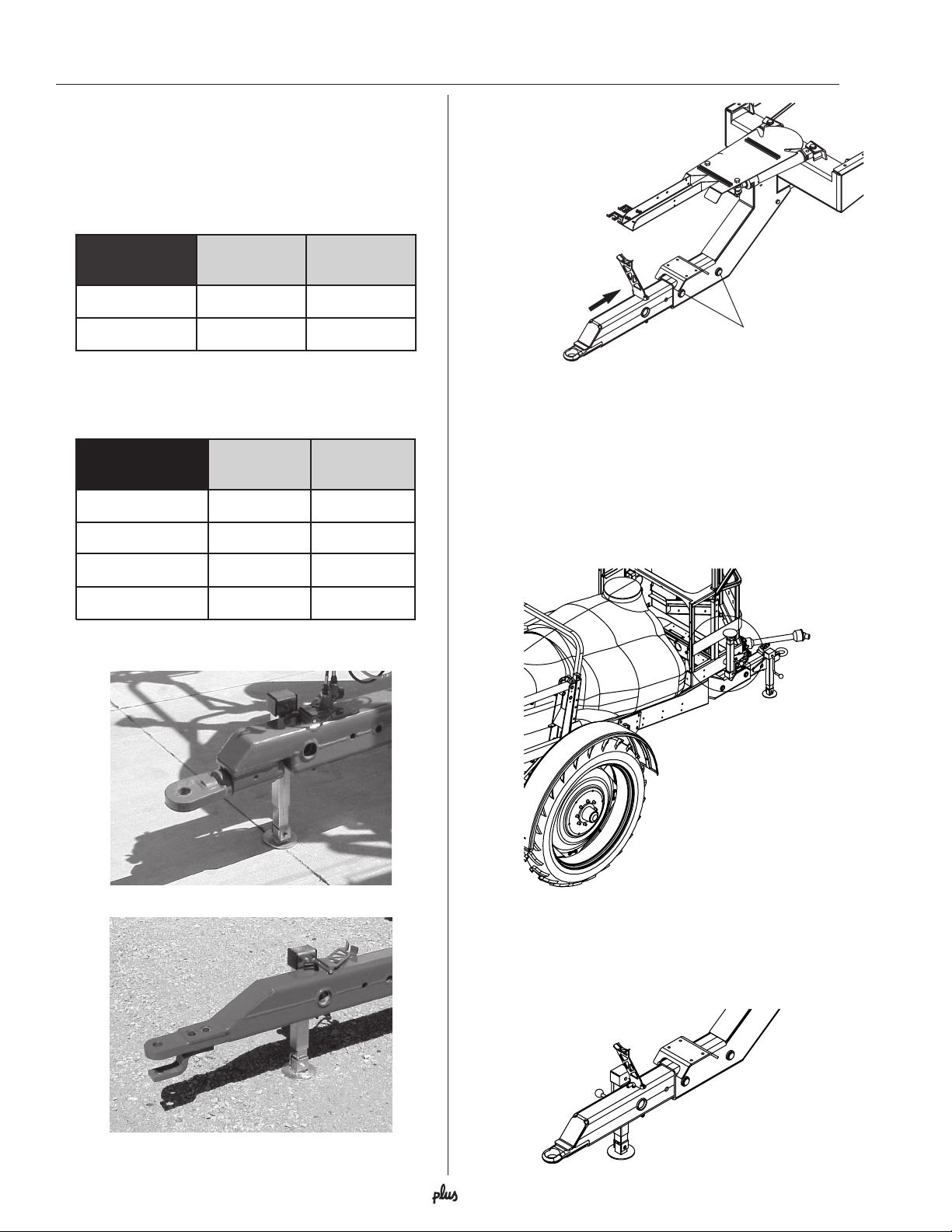
Mounting the drawbar hitch
The drawbar hitch is inserted into
the opening of the drawbar,
fastened by two pins through
the two holes A and secured
by two roll pins.
A
Drawbar hitch height adjustment
The drawbar hitch may be inverted for height adjustment. Remove the two pins (A) and the P.T.O. support
bracket. Invert the drawbar hitch and replace the two
pins (A) and P.T.O. support bracket.
Support jack
The support jack is stored upside-down in the bracket
on the sprayer’s right side when the sprayer is attached
to the tractor.
Clevis type Ø42
Swivel type
Clevis type
No
Yes
To remove the support jack from the drawbar hitch: Lift
the leg, remove the linch pin and pull out the support
jack. The support jack can then be mounted to the
storage bracket and secured by the linch pin.
10 HARDI® COMMANDER OPERATOR’S MANUAL
Page 13
Sprayer setup
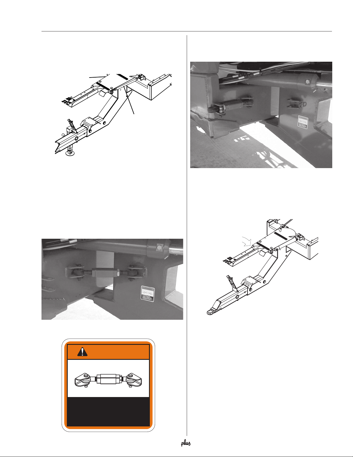
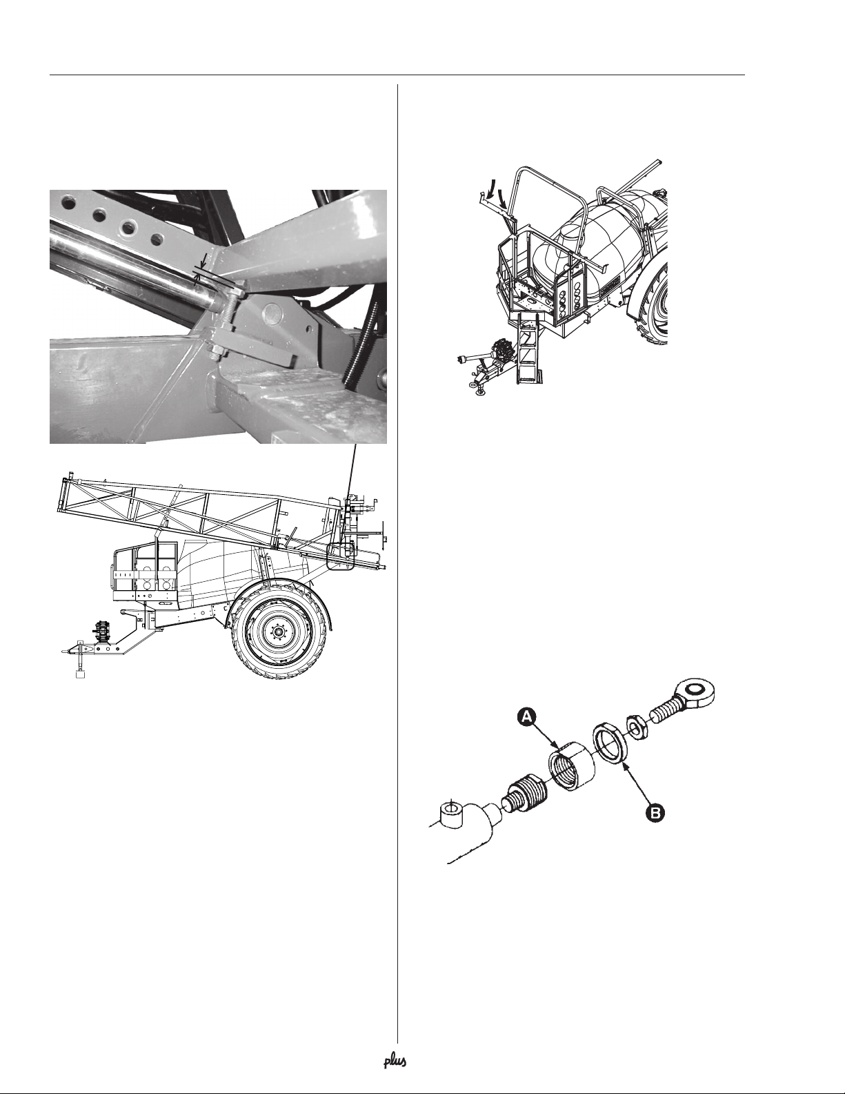
Fixed drawbar adjustment
Make sure the drawbar points straight ahead from its
position on the trailer. If not, the two turnbuckles A can
be adjusted until the drawbar is centered.
A
A
STEERING drawbar (optional)
Transport lock (if fitted)
The transport lock is a safeguard that will keep the
drawbar in a centered position in case of hydraulic
leakage during transport on public roads.
The transport lock is held in place by pins and snap
rings. If necessary, the transport lock can be adjusted
by turning the turnbuckle.
When the hydraulic steering is needed again, remove
the front pin and snap ring, swing the transport lock out
to the field position and secure with pin and snap ring.
Transport lock - Field position
Hose package support
To prevent hoses and wiring from being damaged by
the tractor wheels, all hoses, cables and wires are held
by the hose bracket A fitted to the drawbar.
A
Transport lock - Road position
WARNING
DO NOT TRANSPORT
WITHOUT LOCKING THIS
STEERING DRAWBAR INTO
TRANSPORT POSTION.
Check that the length of the hoses and cables is
sufficient in tight turns, especially when the optional
steering drawbar is fitted.
97604303
11HARDI® COMMANDER OPERATOR’S MANUAL
Page 14
Sprayer setup
P. T.O. Shaft Operator Safety
WARNING:
ATTACHING THE TRANSMISSION SHAFT
TO TRACTOR P.T.O. MOST TRACTOR P.T.O.
SHAFTS CAN BE ROTATED BY HAND TO FACILI
SPLINE ALIGNMENT WHEN ENGINE IS STOPPED.
When attaching the shaft, make sure that the snap lock
is FULLY ENGAGED - push and pull shaft until it locks.
WARNING:
SHAFTS WITHOUT PROTECTION GUARDS
ARE FATAL.
Always keep protection guards and chains intact and
make sure that the guards cover all rotating parts,
including CV-joints at each end of the shaft.
Do not use without protection guard.
Do not touch or stand on the transmission shaft when it
is rotating - safety distance: min 5’ (1.5 meters).
Prevent protection guards from rotating by attaching
the chains, allowing sufficient slack for turns.
Make sure that protection guards around the tractor
P. T.O. and implement shaft are intact. Always STOP
ENGINE and remove the ignition key before carrying
out maintenance or repairs to the transmission shaft or
implement.
ALWAYS STOP ENGINE BEFORE
TATE
ROTATING TRANSMISSION
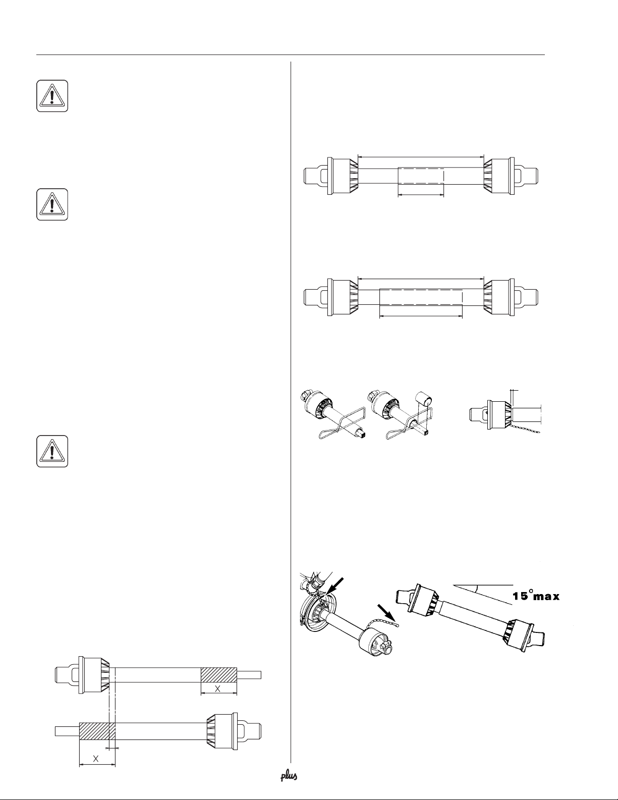
Note: The minimum allowable overlap for the shaft
depends on the pump model.
Pump with 6 splines (540 r.p.m.)
The shaft must always have a minimum overlap of 1/3
the length.
Length
Min. 1/3 of Length
Pump with 21 splines (1000 r.p.m.)
The shaft must always have a minimum overlap of 2/3
the length.
Length
Min. 2/3 of Length
4. The two parts are shortened equally. Use a saw, and
file the profiles afterwards to remove burrs.
Min. 13/16” (20mm)
INSTALLATION OF P.T.O. SHAFT
WARNING:
CHANGE WHEN RAISING AND LOWERING
THE CLEVIS. TO PREVENT EXCESSIVE
LOADING AND BINDING ON THE P.T.O. SHAFT, IT
MAY BE ADVISABLE TO LEAVE THE P.T.O. SHAFT
DISCONNECTED UNTIL THE CLEVIS ADJUSTMENT
IS COMPLETED. THEN THE P.T.O. SHAFT ADJUSTMENTS CAN BE MADE.
Initial installation of the shaft is done as follows:
1. Attach sprayer to tractor and set sprayer in the
position with shortest distance between the tractor
and sprayer pump P.T.O. shafts.
2. Stop engine and remove ignition key.
3. If P.T.O. shaft must be shortened, the shaft is pulled
apart. Fit the two shaft parts at tractor and sprayer
pump and measure how much it is necessary to
shorten the shaft. Mark the protection guards.
THE P.T.O. SHAFT ANGLE WILL
5. Grease the profiles, and assemble male and female
parts again.
6. Fit the shaft to tractor and sprayer pump.
Note: Female part towards tractor. Fit chains to prevent
the protection guards from rotating with the shaft.
7. To ensure long life of the P.T.O. shaft, try to avoid
working angles greater than 15°.
Min 13/16" (20mm)
12 HARDI® COMMANDER OPERATOR’S MANUAL
Page 15
Sprayer setup
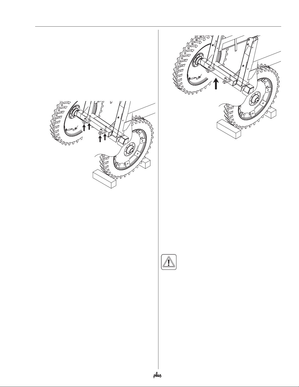
Wheel tread adjustments
Altering the wheel track width
The track width of the COMMANDER Plus can be
adjusted as follows:
1. Measure the current track (center RH tire to center
LH tire). Each side must be extended or retracted
half the desired adjustment.
2. Attach the sprayer to tractor and engage tractor
parking brake.
A
A
3. Place wheel stops in front of and behind the RH
wheel. Jack up the LH wheel, support and secure
the sprayer frame.
4. Loosen the axle clamp bolts A for the LH wheel axle.
5. Extend or retract the axle as needed.
IMPORTANT! Place the jack under the axle and lift the
wheel to remove any load from the axle clamps before
tightening the axle clamp bolts to the specified torque.
6. Tighten the clamp bolts to a torque of:
207 Ft/lb (280 Nm) for CM+ 750
289 Ft/lb (390 Nm) for CM+ 1200
7. Repeat the procedure for the RH wheel.
8. Make sure the distance from the center of the tire to
the center of the tank frame is equal on RH and LH
sides.
9. Retighten the axle clamp bolts and wheel bolts to
specified torque after 10 hours of operation.
IMPORTANT! With Drawbar Steering
models, a minimum track width of
72” is required to ensure stability
and to prevent the sprayer from
tipping over.
Note: The wider the track width, the better is the
stability of the sprayer and boom.
13HARDI® COMMANDER OPERATOR’S MANUAL
Page 16

Sprayer setup
Axle Systems & Tire Assemblies
COMMANDER PLUS 750
• 60”- 88” adjustable axle inserts with 2 x 12.4 x 42” tire assemblies
• 120” fixed axle with 2 x 12.4 x 42” tire assemblies
COMMANDER PLUS 1200
• 60”- 90” or 72”- 90” adjustable axle inserts with 2 x 320/90R46” tire assemblies
(Note: 60”- 90” axle system ONLY available with EAGLE™ booms)
• 120” fixed axle with 2 x 320/90R46” tire assemblies
• 60”/120” Dual Wheel axle with 4 x 320/90R46” tire assemblies for 30” rows
• 88”/132” Dual Wheel axle with 4 x 270/95R48” tire assemblies for 22” rows
• 72”- 90” coil spring suspended adjustable axle inserts with 2 x 320/90R46” tire assemblies
• 76”- 90” or (80”- 90”) coil spring suspended adjustable axle inserts with 2 x 380/90R46” or
(2 x 18.4R46”) tire assemblies
• 120” coil spring suspended fixed axle system with 2 x 320/90R46” or 2 x 380/90R46” or
2 x 18.4R46” tire assemblies
• 88”/132” coil spring suspended Dual Wheel axle with 4 x 270/95R48” tire assemblies for 22”
rows
IMPORTANT! With Drawbar Steering models, a minimum track width of 72” is
required to ensure stability and to prevent the sprayer from tipping over.
Note: The wider the track width, the better is the stability of the sprayer and boom.
14 HARDI® COMMANDER OPERATOR’S MANUAL
Page 17
Sprayer setup
Hydraulic system
Connection requirements for HZ booms are:
• One single acting outlet for the lift function of the
spray boom
• One double acting outlet for the folding function
• 12 Volt electric supply
Note: The hydraulic system requires an oil capacity of
approximately 0.8 GPM (3 liters) and a minimum
pressure of 1,950 PSI (130 bar).
BE SURE TO HOOK UP HYDRAULIC LINES
PROPERLY!
ENSURE HYDRAULIC LINES HAVE NOT BEEN
DAMAGED DURING SHIPPING.
ESCAPING HYDRAULIC FLUID UNDER PRESSURE
CAN PENETRATE THE SKIN CAUSING SERIOUS
INJURY. AVOID THIS HAZARD BY RELIEVING
PRESSURE BEFORE DISCONNECTING HYDRAULIC LINES.
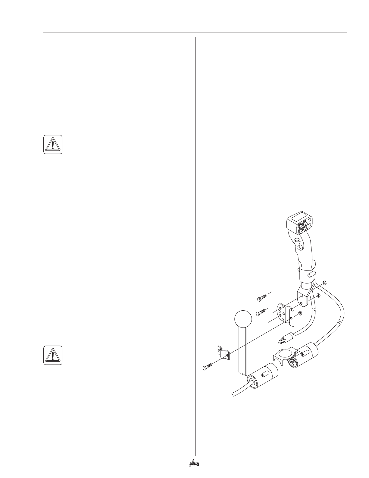
Hydraulics - standard joystick handle
Installation of handle
1. Attach the control handle/joystick A to the hydraulic
lever that operates the double acting outlet to be
used. The universal mounting bracket B is very
flexible and a number of different mounting positions
can be used.
2. Connect the plug C to the tractor’s 12V power
system. Try to hook-up the handle as close as
possible to the battery power supply. HARDI
mends using an electric distribution box (ref. no.
817925) to ensure a good power supply to various
12V attachments.
Note: Check with your dealer or tractor operator’s
manual for the best location to hook up the 12V system.
Note polarity: BROWN wire = Positive (+)
BLUE wire = Negative (-)
3. Connect electric plug D from sprayer’s hydraulics to
plug E on handle.
®
recom-
ENSURE ALL CONNECTIONS ARE TIGHT BEFORE
APPLYING PRESSURE, SEARCH FOR LEAKS WITH
A PIECE OF CARDBOARD NOT YOUR HANDS!
IMPROPER HOOK-UP CAN CAUSE DANGEROUS
BOOM MOVEMENTS AND/OR DAMAGE TO THE
SPRAYER HYDRAULICS.
DO NOT ALLOW ANYONE NEAR A HYDRAULIC
BOOM IN OPERATION.
ALWAYS SHUT TRACTOR OFF WHEN CONNECTING, SERVICING OR ADJUSTING BOOM.
Make sure that the hydraulic couplers are clean before
connecting to the tractor’s remote outlets.
IMPORTANT! Due to the variation in tractor
hydraulic systems and capacities, care should
be exercised when initially operating the
sprayer hydraulic cylinders. It is advisable to adjust the
hydraulic flow control down to the minimum rate before
operating the system. Adjust/increase the flow control
after the system is bled of any air, if necessary.
A
B
Hydraulic lever
C
E
D
15HARDI® COMMANDER OPERATOR’S MANUAL
Page 18
Sprayer setup
Direct Acting Hydraulic system (D.H.)
(optional)
Installation of control box
1. Connect the plug A to the tractor’s 12V power
system. Try to hook up the handle as close as
possible to the battery power supply. HARDI
recommends using an electric distribution box (ref.
no. 817925) to ensure a good power supply to
various 12V attachments.
Note: Check with your dealer or tractor operator’s
manual for the best location to hook up the 12V system.
Note polarity: BROWN wire = Positive (+)
BLUE wire = Negative (-)
2. Route the cable with the 7 pins, from the sprayer’s
hydraulic mount plate to the tractor.
3. Mount the hydraulic control box B in a suitable
location in the tractor cabin.
4. Connect the female 7 pin plug C from the switch box
to the 7 pin male plug D from the sprayer.
A
B
®
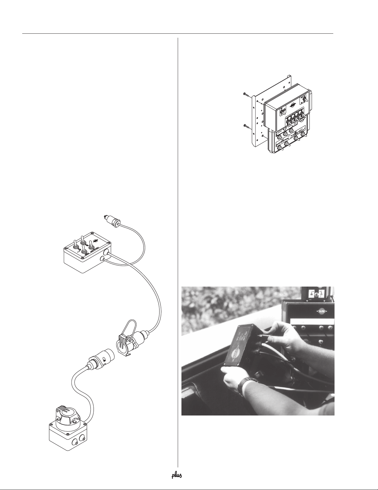
Control boxes and power supply
The control boxes for the ECP operating unit are fitted
in the tractor cabin in a convenient place. Self-tapping
screws can be used for mounting.
Ø4.8 x 9.5mm
Ø4.8 x 12mm
Power requirement is 12V DC.
Note polarity: BROWN wire = Positive (+)
BLUE wire = Negative (-)
The wires must have a cross sectional area of at least
12wg (4 mm
the ECP operating unit the tractor circuit should have
an 8 Amp fuse (5 Amp fuse for hydraulic system).
The 12V power sockets on the control boxes can be
plugged directly into either a HARDI
tion box (#817925) or a single female bayonet style
plug (#260827). Both of these are available from your
HARDI® Dealer.
2
) to ensure sufficient power supply. For
®
4 outlet connec-
C
D
12-volt junction box (#817925) for 12-volt hook-up.
16 HARDI® COMMANDER OPERATOR’S MANUAL
Page 19
Sprayer setup
Transport
Roadworthiness
Slow moving tractors and spray equipment can create
a hazard when on public roads. Make sure the S.M.V.
sign is in place and clearly visible from the rear of the
sprayer.
NOTE! Max. driving speed is 15 mph (25 km/h).
Transport brackets, height setting
The transport brackets can be set in different positions
to obtain different transport heights and suitable clearance above various tractor cabins.
When changing the setting of the transport brackets it
is done as a combination of adjusting the transport
brackets themselves (1) and adjusting the transport
locks (2). Always choose a transport height as low as
possible.
1. Transport brackets
(1)
The transport bracket can be set at
three different positions A, B or C.
A
Loosen the bolt to change position
B
and replace it according to new
setting. The setting must be identical
C
on both sides.
Rear lights
Local regulations may require the use of flashing
warning lights. Connect plug for rear lights to the
tractor’s 7-pin socket, and check function of rear lights,
stop lights and direction indicators on both sides before
driving.
(2)
A
2. Transport lock
To change position:
1. Lift and unfold inner sections till lock is disengaged.
2. Loosen and remove the two bolts, which keep the
parts A and B assembled.
3. Reassemble A and B according to desired hole
combination.
Note: Always use both bolts to assemble the lock. The
setting must be identical on both sides.
Note: The rear settings must correspond to the front
settings so the boom is resting on the front as well as
rear locks.
B
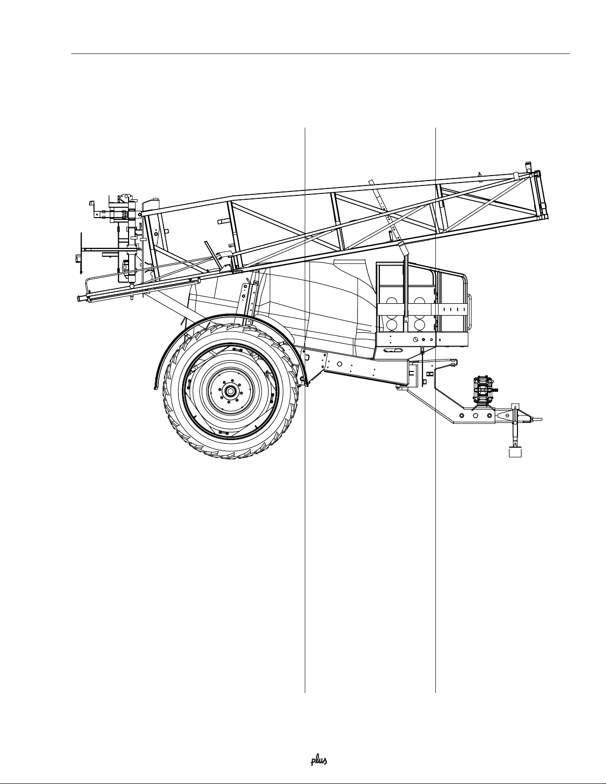
WARNING! The max. transport height must
never exceed 13.1 ft. (4.0 m). Always measure
the actual total height and choose settings not
exceeding 13.1 ft (4.0m).
17HARDI® COMMANDER OPERATOR’S MANUAL
Page 20
Sprayer setup
Transport lock arm stop
When the boom is unfolded: Inspect the gap between
the bolt A and the frame. Correct position = 1/16” gap
(2 mm).
If necessary, adjust the position of bolt A.
1/16” (2 mm)
A
Adjusting boom transport position
If the boom wings do not rest accurately in the transport brackets, the wings can be adjusted as described
below:
1. Lift the boom all the way to the top.
2. Fold the boom into transport position. With the fold
cylinder pressurized, determine if the boom wings
need to be adjusted inwards or outwards.
3. Relieve the pressure from the fold cylinder by unfolding the boom a few inches.
If the boom rests too far in on the transport brackets,
loosen the nut B and adjust collar A in towards the
cylinder housing.
If the boom rests too far out on the transport brackets,
the collar A has to go out from the cylinder housing.
4. Secure jam nut B.
5. Pressurize the cylinder to see if the boom is properly
adjusted. If not, repeat the above procedure until it is
correctly adjusted.
18 HARDI® COMMANDER OPERATOR’S MANUAL
Page 21
Sprayer setup
Driving Technique
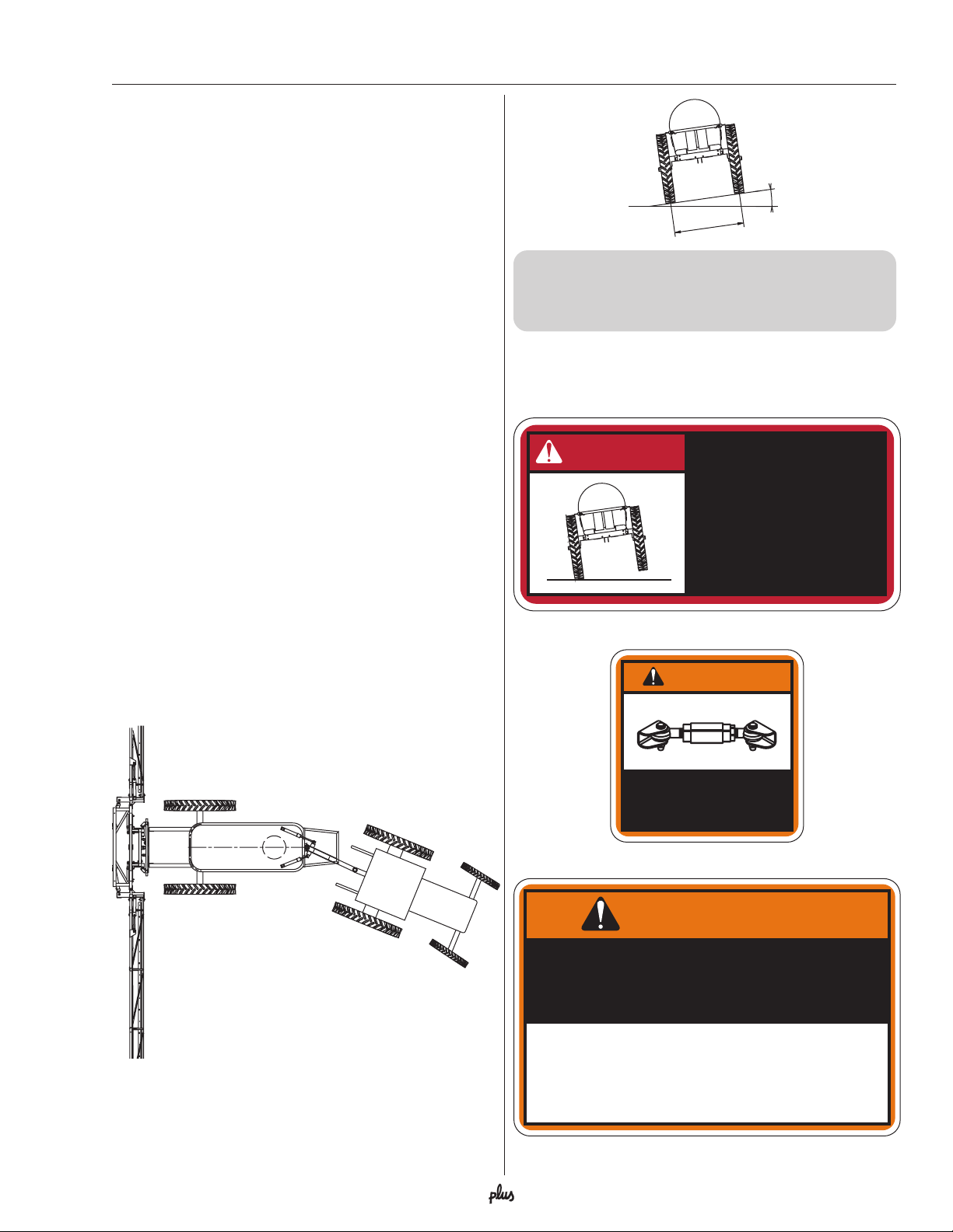
Steering drawbar (optional)
A trailer with an articulating drawbar behaves differently
than a normal trailer.
In tracking position the vehicle’s center of gravity is
displaced further from the vehicle’s center line than that
of a normal trailer.
Compared to a conventional trailer, a trailer equipped
with a steering drawbar has decreased stability when
turning, especially when turning on hillsides.
To avoid instability or overbalancing, pay attention to
these guidelines:
1. Avoid sudden, tight turns
2. Slow down before entering a curve or turning, and
drive with a constant, low speed during the turn.
3. Never slow down too fast, never brake heavily and
never stop suddenly in a curve, or when turning on a
hillside, when the sprayer is articulated.
4. Be careful when turning on uneven ground
5. Set the wheel width as wide as possible
6. The proper function of the hydraulic damping is
essential to obtain good stability
7. Keep stabilizer chains on the tractor’s liftarms tight
8. For safety reasons, the following limitations are set
for sprayers equipped with steering drawbar (with
unfolded booms):
MAX. 8º
MIN. 72"
Speed while turning, max. 2.5 m.p.h. (4 km/h)
Ground inclination while turning, max. 8°
Wheel width, min. 72” with steering drawbar
Make sure the following safety decals are in place and
that you understand and follow each one:
DANGER
USING THE STEERING
DRAWBAR WILL
DECREASE SPRAYER
STABILITY. USE
EXTREME CAUTION!
97604203
Decal #97604203
WARNING
DO NOT TRANSPORT
WITHOUT LOCKING THIS
STEERING DRAWBAR INTO
TRANSPORT POSTION.
97604303
Decal #97604303
WARNING
DO NOT USE STEERING DRAWBAR
WITH SPRAYER/AXLE CONFIGURATION
OTHER THAN THOSE LISTED BELOW:
CM Plus 750 .............SPB EAGLE™ BOOM ............72" OR WIDER AXLE
CM Plus 875/1200 ....SPB/SPC EAGLE™ BOOM ...72" OR WIDER AND DUALS
CM Plus 875/1200 ....FORCE™ BOOM ...................120" AND DUALS
CM Plus 750 .............TWIN FORCE ........................72" OR WIDER AXLE
CM Plus 875 .............TWIN FORCE UP TO 66' .......72" OR WIDER AXLE
CM Plus 875 .............TWIN FORCE 80'-90' ............120" AND DUALS
CM Plus 1200 ...........TWIN FORCE 60'-90' ............120" AND DUALS
Decal #97604403
97604403
19HARDI® COMMANDER OPERATOR’S MANUAL
Page 22
Sprayer setup
Disconnecting the sprayer
Always clean the sprayer - inside and outside - before
disconnecting and parking it.
Support leg
Before disconnecting the sprayer from the tractor,
make sure the support leg is properly fitted with the
linch pin secured.
The support leg is stored in the storage bracket on the
right side of the trailer when the sprayer is attached to
the tractor. To remove the support leg: Lift the leg,
remove the pin and pull out the support leg.
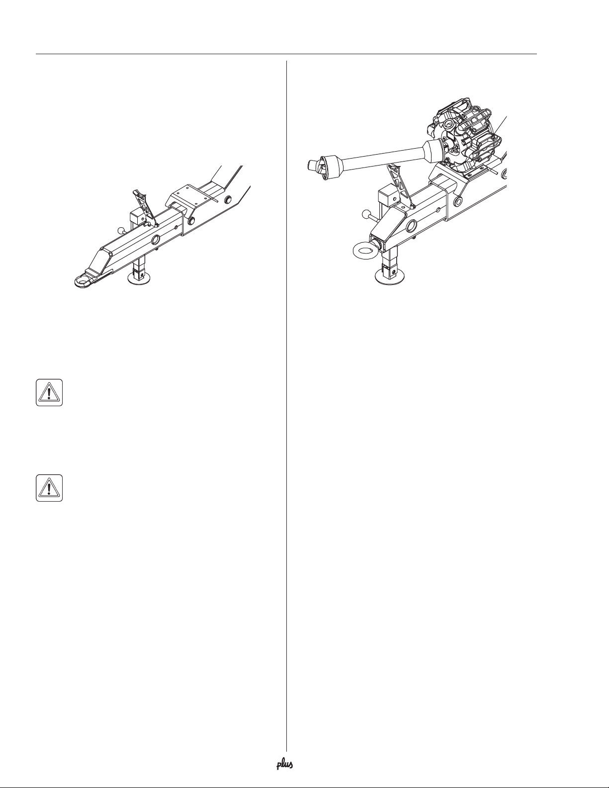
P. T.O. shaft support
The P.T.O. shaft rests on the bracket A when not in use.
A
WARNING! To prevent the sprayer from tipping
over, do not disconnect the sprayer from the
tractor with the booms unfolded unless the
boom is supported!
Remember to disconnect all hoses and cables from the
tractor.
WARNING! If the sprayer is parked unattended
avoid unauthorized persons, children and
animals from having access to the sprayer.
20 HARDI® COMMANDER OPERATOR’S MANUAL
Page 23

Operation
Operating the boom
BEFORE UNFOLDING THE BOOM, IT IS
IMPORTANT TO HAVE THE SPRAYER
HOOKED TO THE TRACTOR TO PREVENT
OVERBALANCING THE SPRAYER. ONLY THEN
LIFT THE BOOM OFF THE TRANSPORT BRACKETS WHICH HOLD IT IN THE TRANSPORT POSITION.
• ENSURE THAT BOOMS ARE BACK IN THE
TRANSPORT POSITION BEFORE UNHOOKING
THE SPRAYER FROM THE TRACTOR.
• THE HYDRAULIC SYSTEM SHOULD BE CHECKED
VERY CAUTIOUSLY THE FIRST TIME OF OPERATION; THERE MAY BE AIR IN THE SYSTEM AND
THIS COULD CAUSE VIOLENT MOVEMENTS OF
THE BOOM. ENSURE THAT NO PERSONS OR
OBJECTS ARE IN THE WAY WHILE CHECKING
THE SYSTEM.
• FOR INFORMATION ON BOOM ADJUSTMENT,
SEE THE APPROPRIATE EAGLE™ OR FORCE™
BOOM OPERATOR’S MANUAL.
Unfolding and folding the HZ EAGLE™ boom
WARNING! Always put the boom wings in the
horizontal position prior to folding. Never at-
tempt to fold the boom to transport position
when the boom wings are tilted - unexpected boom
movements may occur, if the wings are tilted when
folding.
A. Hydraulic joystick controls
Switch A operates: Left hand fold cylinder
Switch B operates: Right hand fold cylinder
Switch C operates: Left hand tilt cylinder
Switch D operates: Right hand tilt cylinder
A
C
B
D
1. Raise the boom to release it from the transport
brackets.
2. Depress switches A and B and move the joystick
forward or rearward to activate oil flow. Switch
positions of the hoses in the double acting remote
outlet if you do not like the direction required to
activate the boom.
3. ‘One side folding’ is achieved by following the above
procedure - except that only one of the switches is
depressed (See
‘Folding one side only’
below).
B. D.H. Hydraulic control box (optional)
Switch A operates: Left hand fold cylinder
Switch B operates: Right hand fold cylinder
Switch C operates: Left hand tilt cylinder
Switch D operates: Right hand tilt cylinder
C
A
D
B
1. Raise the boom to release it from the transport
brackets.
2. Engage the tractor’s double acting remote outlet
lever and lock it in the engaged position.
3. Activate switch A upwards and hold it to unfold left
hand boom wing. (Holding the switch in the ‘down’
position will fold the boom wing). To unfold right hand
boom, activate switch B.
4. ‘One side folding’ is achieved by following the above
procedure - except that only one of the switches is
activated. (See section
Folding one side only
If only one side of the boom is to be unfolded, first
unfold the boom completely and then turn switches off.
Then flip the switch for the side that is to be folded and
activate the double acting outlet to fold that side into
transport position.
Note: It is not advisable to go directly from transport
position to spraying position with one side only. Therefore, first unfold both boom wings completely.
‘Folding one side only’
).
21HARDI® COMMANDER OPERATOR’S MANUAL
Page 24

Operation
Unfolding and folding the HZ FORCE™ boom
WARNING! Always operate the boom on level
ground.
A. Hydraulic joystick controls
Switch A operates: Inner wing fold cylinders
Switch B operates: Outer wing fold cylinder
Switch C operates: Left hand tilt cylinder
Switch D operates: Right hand tilt cylinder
A
C
B
D
3. Tilt wings up approx. 15° (See Tilting the HZ Force™
boom - p. 23).
4. Depress switch A to fold in the inner wing sections
allowing the bottom profile of the wing to come in
contact with the vertical part of the front transport
bracket.
5. Lower boom down, activating the Paralift™ lift
cylinders. Make sure that the transport hooks are
engaged on the cylinders. Then lower the tilt cylinders (switch C and D) until the wings are resting on
the front transport supports.
6. Relieve all oil out of the system by activating the
tractor levers without any switches pushed.
B. D.H. Hydraulic control box (optional)
Switch A operates: Left hand fold cylinder
Switch B operates: Right hand fold cylinder
Switch C operates: Left hand tilt cylinder
Switch D operates: Right hand tilt cylinder
C
A
D
TO UNFOLD BOOM
1. Raise the boom to release it from the transport
brackets.
2. Depress switches A and move the joystick forward or
rearward to unfold the inner wing sections of the
boom. Switch positions of the hoses in the double
acting remote outlet if you do not like the direction
required to activate the boom.
Note: When unfolding the inner wings, the transport
hooks on the two Paralift™ cylinders will disengage.
3. With the boom still at the highest point, depress
switch B to unfold the outer wing sections (unless
spraying half folded). Lower boom to desired spray
height.
TO FOLD BOOM
1. Raise the boom 75% of the highest point.
2. Depress switch B and move joystick in opposite
direction as unfold to fold in the outer wing sections.
B
TO UNFOLD BOOM
1. Raise the boom to the highest point to release it from
the transport supports and hooks.
2. Engage the tractor’s double acting remote outlet
lever and lock it in the engaged position.
3. Activate switch A upwards and hold it to unfold the
inner wing sections.
Note: When unfolding the inner wings, the transport
hooks on the two Parilift™ cylinders will disengage.
4. Activate switch B upwards and hold to unfold the
outer wing sections (unless spraying half folded).
Lower boom to desired spray height.
TO FOLD BOOM
1. Raise the boom 75% of the highest point.
2. With the double acting remote outlet lever engaged,
activate switch B downwards and hold to fold in the
outer wing sections.
Note: Be sure that the boom is raised when folding or
damage can occur when the transport hooks are
engaged.
Note: Be sure that the boom is raised when folding or
damage can occur when the transport hooks are
engaged.
22 HARDI® COMMANDER OPERATOR’S MANUAL
3. Tilt wings up approx. 15° (See Tilting the HZ Force™
boom - p. 23).
Page 25

Operation
4. Depress switch A to fold in the inner wing sections
allowing the bottom profile of the wing to come in
contact with the vertical part of the front transport
bracket.
5. Lower boom down, activating the Paralift™ lift
cylinders. Make sure that the transport hooks are
engaged on the cylinders. Then lower the tilt cylinders (switch C and D) until the wings are resting on
the front transport supports.
6. Relieve all oil out of the system by activating the
tractor levers without any switches pushed.
Tilting the HZ FORCE™ boom
WARNING! Never attempt to work on or around
boom when tilted up.
A
B
B. D.H. Hydraulic control box (optional)
1. Engage the tractor’s double acting remote outlet
lever and lock it in the engaged position.
2. Activate switch C upwards and hold to tilt left-hand
boom up (Holding the switch in the down position will
tilt the boom down). To tilt the right-hand boom,
activate switch D.
C
A
D
B
C
D
A. Hydraulic joystick controls
1. Activate switch C and move hydraulic handle forward
or rearward to tilt left-hand boom up. To tilt the righthand boom, activate switch D. Switch positions of
the hoses in the double acting outlet if you do not
like the direction required to activate the boom.
23HARDI® COMMANDER OPERATOR’S MANUAL
Page 26

OperationOperation
The HARDI® COMMANDER Plus trailer sprayer uses a diaphragm pump with ECP control.
Take time to review and study the plumbing diagram for your sprayer. By following the flow
through the diagram, you will better understand the various functions of your sprayer system.
ECP PLUMBING DIAGRAM
7
3
10
4
12
14
9
11
16
1
2
8
15
6
17
5
19
17
18
13
1. Suction filter
2. Suction manifold
3. Pump
4. Pressure manifold
5. Sparge tube agitation
6. Safety valve
7. HARDI-MATIC
8. Self-cleaning filter valve return
9. Self-cleaning filter
10. Check valve
11. Boom section valves
12. Pressure agitation return
with restrictor
13. Boom
14. Boom pressure gauge
15. Flush tank
®
16. HARDI
chemical inductor
17. Tank rinse nozzles
18. Pressure equalization return
19. Feed hose pressure return
24 HARDI® COMMANDER OPERATOR’S MANUAL
Page 27

Operation
Operating the liquid system
MANIFOLD SYSTEM
The “Manifold System” is located at the left side of the
sprayer, permitting operation of most of the (fitted)
accessories from one position. The modular design of
the Manifold system allows the easy addition of many
accessories to the plumbing system of the sprayer. The
system can be expanded to a maximum of 4 valves on
the pressure side. The suction side can be expanded to
a maximum of 2 valves. The system is also fitted with
an agitation valve, enabling the tank agitation to be
turned on or off. It also features a self-cleaning filter
return hose on/off valve, which allows the return to be
turned on or off.
Use of MANIFOLD valve system
The Manifold valve faces are colored discs for easy
identification:
Green disc = Pressure valve
Black disc = Suction valve
Yellow disc = Self-cleaning filter
Closed
A function is activated/opened
by turning the handle
towards the desired
function
Function
open
Decals - Black disc (suction)
Suction from
main tank
Flush tank
(optional)
)retlifgninaelc-fles(csidwolleY
The disc has two
positions; open
Closed
Open
or closed
The valves and functions may vary from machine to
machine depending on optional equipment fitted. Only
the functions to be used must be open - Always close
all remaining manifold valves.
*Agitation
Normally, Agitation should be on, but please refer to
the following rules of thumb:
1. Choose “Without Agitation” if a high level of
foaming occurs, in order to reduce the
amount of foam.
Symbols (shown below) are fitted to the faces of the 3way valves indicating the direction of flow of the liquid.
Decals - Green disc (pressure)
Self-cleaning
filter /
Operating unit
HARDI FILLER
(optional)
Agitation *
Without
agitation
Tank rinsing
nozzle
To main tank
Spray gun
(optional)
®
2. Choose “Agitation” when using powder
chemicals in order to avoid sedimentation.
3. Close the agitation valve if spraying with
a high volume and it is impossible to
achieve sufficient operating pressure.
25HARDI® COMMANDER OPERATOR’S MANUAL
Page 28

Operation
To operate the spraying functions:
• Turn the handle on a green pressure valve towards
the desired function
• Turn the handle on a black suction valve towards the
desired function
• Open or close yellow disc (self-cleaning filter)
• Close all remaining valves by setting the handle(s)
on “O”
Note: If a MANIFOLD valve is too tight to operate - or
if it is too loose (= liquid leakage), the 3-way-valve
needs to be serviced. Please see the part
of 3-way-valve (suction)” (p. 50)
Correct setting is when the valve can be operated
smoothly by one hand
for further information.
Electrical operated MANIFOLD valves
(optional)
One or more MANIFOLD valve(s) can be electrically
operated via a control box in the tractor cab. In case of
a power failure, these can only be operated manually
when the power to the valve motor is disconnected.
Quick reference decals are located on the frame near
the MANIFOLD SYSTEM for easy “in field” operation of
the valves.
“Adjustment
1. Filling main tank through tank lid
Remove the tank lid and fill water through strainer
basket to prevent rust or other foreign particles from
entering the tank.
It is recommended to use a water supply as clean as
possible for spraying purposes.
WARNING!
ETC. ENTER THE TANK. KEEP IT OUTSIDE
THE TANK, POINTING TOWARDS THE
FILLING HOLE.
IF THE HOSE IS LEAD TO THE BOTTOM OF THE
TANK, AND THE WATER PUMP AT THE WATER
SUPPLY PLANT STOPS, CHEMICALS CAN BE
SIPHONED BACK AND CONTAMINATE THE WATER
SUPPLY LINES.
DO NOT LET THE FILLING HOSE
2. Filling flush tank (optional) through lid
The flush tank is situated at the front under the platform
and main tank. Access to the flush tank lid is at the rear
of the platform. Fill only with clean water.
Filling the tanks on the COMMANDER Plus
The main tank and flush tank can be filled in two ways:
1. Filled through tank lid.
2. Filled with external Quick Fill (optional), which
enables the connection to a nurse tank.
Flush tank capacity (optional)
The main tank should normally be filled 1/3 with water,
before adding the chemicals - always read instruction
on chemical container!
IMPORTANT! If the sprayer is stored with liquid in the
main tank, all MANIFOLD valves must be closed.
26 HARDI® COMMANDER OPERATOR’S MANUAL
Model LiterUS Gal.
750
1200
70
110
280
420
Page 29

Operation
3. Filling with external Quick Fill (optional)
Main tank Quick Fill coupler
A water level indicator for the flush tank (clear hose
with floating ball) is situated beneath the platform.
4. Filling of clean water tank
The clean water tank is integrated in the platform and
has a capacity of 8 gallons (30 liters). Access to the
tank lid is possible from the platform. Fill this tank with
clean water only.
Flush tank Quick Fill coupler
The Quick Fill is operated as follows:
1. Remove the plug from the quick fill coupler for the
tank you wish to fill (main tank or flush tank).
2. Fit the external water supply hose to the quick
coupler on the trailer.
3. Fill tank to desired level.
WARNING: Do not leave the sprayer while filling
the tank, and keep an eye on the tank level sight
gauge in order NOT to overfill the tank!
4. Remove external water supply hose from the quick
coupler.
5. Replace the plug on the quick coupler.
Note: Observe local legislation regarding use of Quick
Filling Device. In some areas it is prohibited to fill from
open water reservoirs (lakes, rivers, etc.). It is recommended only to fill from closed reservoirs (mobile water
tank, etc.) to avoid contamination.
WARNING!
CARRIED ON THE SPRAYER, IT CAN BE
CONTAMINATED BY SPRAY DRIFT WHICH
WILL BE TRANSFERRED TO WATER SUPPLY
WHEN FILLING.
IF SUCTION HOSE/FILTER IS
The water from this tank is for hand washing, cleaning
of clogged nozzles etc. The tap is located within reach
from the MANIFOLD valves and is opened/closed by a
tap handle.
WARNING! Although the clean water tank is
only filled with clean water, it must never be
used for drinking.
27HARDI® COMMANDER OPERATOR’S MANUAL
Page 30

Operation
Adjustment of ECP operating controls
Distribution
Valves
Constant Pressure
Adjusting Screws
C
System Pressure
Gauge
Pressure
A
BBBBB
Control
Val ve
Adjustment of constant pressure
Note: Adjust the constant distribution boom pressure
one section at a time as follows: (Start with the
valve turned closed before adjusting).
1. Shut-off the first boom distribution valve switch B.
2. Turn the adjusting screw(s) until the control pressure gauge again shows the same pressure as in
step 6 (to left) (Turn the screw clockwise for higher
pressure, counterclockwise for lower pressure).
3. Turn the first boom distribution valve switch B back
on.
4. Repeat steps 1-3 for the remaining boom distribution
valves.
Note: Hereafter adjustment of the constant boom
pressure will only be needed if you change to nozzles
with other capacities, but not required if only changing
pressure or application rate using the same nozzles.
Operating the control unit while spraying
In order to shut off the entire boom, flip on-off switch A
to the off (red) symbol (up position). This returns all the
pump outputs to the main tank through the return
system. The diaphragm anti-drip valves ensure instantaneous closing of all nozzles.
A. Operating switch for main on/off
B. Operating switch for distribution valves
C. Pressure control switch (to lower or raise)
Before spraying, adjust the ECP operating unit
using clean water (without chemicals).
1. Choose the correct nozzle (pp. 33-34). Make sure
that all nozzles are the same type and capacity.
2. Put the tractor in neutral and adjust the P.T.O. r.p.m.
until the number of revolutions of the pump corresponds to the intended traveling speed. Remember
the number of revolutions on the P.T.O. must be kept
between 300-600 r.p.m. (540 r.p.m. pump) or 6501100 (1000 r.p.m. pump) to ensure correct operation
of the HARDI-MATIC system.
3. On-off switch A is “ON” against green symbol (down
position).
4. All distribution valve switches B are also “ON”
against green symbol (down position).
5. Hold pressure regulating switch C down (-) until
handle stops rotating. This will be the “minimum
pressure” setting.
6. Hold pressure regulating switch C up (+) until desired pressure is shown on the boom pressure
gauge.
In order to shut off one or more sections of the boom,
switch the relevant distribution valve B to off position.
The constant pressure system ensures that the pressure does not increase in the sections which are still
open.
In case of electrical failure, it is still possible to manually override all functions of the operating unit. To
operate manually, disconnect the multiplug from the
ECP control box first and operate the handles by hand.
It is possible to change pressure and turn boom sections on or off.
Note: Since the on-off switch normally operates by
shutting off all the boom distribution valves, you will
need to manually shut off all the distribution valves to
shut off the complete control unit manually.
IMPORTANT! When the sprayer is stored,
the ECP control box and the multiplug must
be protected against moisture and dirt. A
plastic bag may be used to protect the multi plug.
Store the control box in a clean dry place.
28 HARDI® COMMANDER OPERATOR’S MANUAL
Page 31

Operation
Remote 4” pressure gauge
The remote pressure gauge is integrated into the front
locker. This gauge measures the working pressure in
the boom tubes as close to the nozzles as possible.
This pressure reading will always be slightly lower than
the reading at the operating unit pressure gauge.
The outputs stated in the nozzle charts are always
based on the pressures measured at the nozzle.
Note:
Always adjust pressure when calibrating and spray-
ing according to readings at the Remote pressure gauge.
Self cleaning filters
This filter automatically flushes out particles and
chemical deposits, reducing routine maintenance,
nozzle plugging and operator exposure. No adjustments are required, but different mesh screens may be
installed for various types of products. The mesh size
of the filter in use should always be smaller than the
flow average of the nozzles used.
Operating diagram
1. From pump
2. Double filter screen
3. Guide cone
4. To operating unit
5. Replaceable restrictor
6. Return to tank
7. Screw-joint
The self-cleaning filter is operated via
the yellow MANIFOLD valve.
IMPORTANT! The yellow MANIFOLD valve should
normally be open, but must be closed in the following
cases:
1. If rinsing with water from the flush tank and a quantity of spray liquid still remains in the main tank
(otherwise the spray liquid will be diluted).
2. If opening the self-cleaning filter and a quantity of
spray liquid still remains in the main tank (otherwise
there is a risk that spray liquid will flow out).
Choice of correct restrictor for S.C.F.
It is important to have a large flow through the self
cleaning filter. This is achieved by choosing the
restrictor size in relation to the liquid consumption of
the spray boom.
The hose (A) is unscrewed
from the self-cleaning filter.
Be careful not to lose the
seal ball or spring when
the restrictor is put in the
hose and the hose is
refitted. If the required
working pressure can not
be obtained, the restrictor
is too large. 4 restrictors
are supplied. Use the
green one (largest orifice)
first. Then choose the next
smaller restrictor, starting
with black, then white and finally a red one.
Adjustment of Air Pressure in Pressure
Damper (1302 Pump Only)
The air pressure in the damper on
the 1302 pump is factory preset at
30 psi (2 bar). This is suitable for
nozzle spray pressures between
45 psi (3 bar) and 225 psi (15
bar). If different nozzle pressures
are required, set pressure damper
at pressures indicated.
PSI (BAR)
20-45 (1-3)
45-225 (3-15)
PSI (BAR)
0-15 (0-1)
15-45 (1-3)
Open
Closed
29HARDI® COMMANDER OPERATOR’S MANUAL
Page 32

Operation
Filling of chemicals
Chemicals can be filled into the tank two different ways:
1. Through the tank lid.
2. By using the HARDI® CHEMICAL FILLER device.
WARNING! Be careful not to slip or splash
chemicals when carrying chemicals up to
the tank lid!
WARNING! Always use the personal protection stated on the chemical container and as
a minimum, always use gloves, face protec-
tion shield and coveralls.
1. Filling through tank lid
The chemicals are filled through the tank lid - Note
instructions on the chemical container!
1. Make sure the ECP is switched off.
2. Set the MANIFOLD valves to correct position. Black
valve “Suction from main tank”, green valve towards
“Agitation.”
Black Green Green Green
3. Engage the pump and set P.T.O. revolutions to 540
r.p.m. or 1000 r.p.m. (depending on pump model).
4. Add the chemicals through the main tank hole.
5. When the spray liquid is well mixed, turn handle on
the Pressure Manifold towards “Spraying” position.
Keep P.T.O. engaged so the spray liquid is continuously agitated until it has been sprayed on the crop.
2. Filling with HARDI® CHEMICAL FILLER
To get access to the HARDI® CHEMICAL FILLER,
grab the handle, disengage the lock with your foot, and
drag the HARDI
down. After use, push it all the way up again.
®
CHEMICAL FILLER all the way
Operating with Liquid-based chemicals
1. Fill the main tank at least 1/3 with
water (unless something else
is stated on the chemical
container label). See
“Filling the tanks on the
COMMANDER Plus”
(pp.26-27).
2. Turn the handle
at the Suction
Manifold towards “Main
tank” . Turn green valve
towards “HARDI
CHEMICAL FILLER” and
other green valve towards
agitation. Close remaining valves.
3. Check that bottom valve A at the FILLER is closed.
®
C
B
A
Black Green Green Green
4. Engage the pump and set P.T.O. speed at 540 r/min
Black Green Green Green
30 HARDI® COMMANDER OPERATOR’S MANUAL
or 1000 r/min (depending on pump model).
5. Open HARDI® CHEMICAL FILLER lid.
6. Measure the correct quantity of chemical and fill it
into the hopper.
Page 33

Operation
Note: The measuring scale in the hopper can only be
used if the sprayer is parked on level ground! It is
recommended to use a measuring jug for best accuracy.
7. Open the bottom valve A. The chemical is then
transferred to the main tank.
8. If the chemical container is empty, it can be rinsed by
using the Bag & Bottle Rinse (optional). Place the
container over the multi-hole nozzle and press the
lever B.
WARNING! Do not press lever B unless the
multi-hole nozzle is covered by a container to
avoid spray liquid hitting the operator.
IMPORTANT! The Bag & Bottle Rinse uses spray liquid
from the main tank to rinse containers of concentrated
chemicals. Always rinse the chemical containers with
clean water several times until they are clean before
disposal.
9.
Engage the hopper rinsing device by opening valve C.
10. Close valve C again when the hopper is rinsed.
IMPORTANT! The hopper rinsing device uses spray
liquid from the main tank for rinsing the hopper of
concentrated chemical. The HARDI
®
CHEMICAL
FILLER must always be cleaned together with the rest
of the sprayer when the spray job is done.
11. Close valve A and the HARDI
®
CHEMICAL FILLER
lid again.
12. When the spray liquid is well mixed, turn handle on
the Pressure Manifold towards “Spraying” position.
Keep P.T.O. engaged so the spray liquid is continuously agitated until it has been sprayed on the crop.
3. Engage the pump and set
P. T.O. speed at 540 r.p.m. or
1000 r.p.m. (depending on
pump model).
4. Open the bottom valve A on
®
the HARDI
CHEMICAL
FILLER and open the lid.
Engage the hopper rinsing
5.
device by opening valve C.
6. Measure the correct
quantity of chemical
and sprinkle it into
the hopper as fast
as the rinsing
device can flush
B
it down.
7. If the chemical
container is empty it
can be rinsed by using
the Bag & Bottle Rinse
C
A
(optional). Fit the bag
bracket and place the
powder bag over the multi-hole nozzle and press the
lever B.
WARNING! Do not press lever B unless the
multi-hole nozzle is covered by a container to
avoid spray liquid hitting the operator.
IMPORTANT! The Bag & Bottle Rinse uses spray liquid
from the main tank to rinse containers of concentrated
chemicals. Always rinse the chemical containers with
clean water several times until they are clean before
disposal.
9. Close valve C again when the hopper is rinsed.
Operating with Powder-based chemicals
Black Green Green Green
1. Fill the main tank at least half full with water, unless
something else is stated on the chemical container
label. See section
Filling of Water
2. Turn the handle at the suction Manifold towards
“Main tank” and green valve towards “Agitation”.
Turn the handle at the Pressure Manifold towards
“HARDI
®
CHEMICAL FILLER”. Close remaining
valves.
.
IMPORTANT! The hopper rinsing device uses spray
liquid from the main tank for rinsing the hopper of
®
concentrated chemical. The HARDI
CHEMICAL
FILLER must always be cleaned together with the rest
of the sprayer when the spray job is done.
10. Close valve A and the FILLER lid again.
11. When the spray liquid is well mixed, turn handle on
the Pressure Manifold towards “Spraying” position.
Keep P.T.O. engaged so the spray liquid is continuously agitated until it has been sprayed on the crop.
31HARDI® COMMANDER OPERATOR’S MANUAL
Page 34

Operation
Use of flush tank and rinse nozzles
(optional)
The incorporated flush tank can be used for two different purposes.
A. In-field diluting of remaining spray liquid residue in
the spraying circuit for spraying the liquid in the field,
before cleaning the sprayer.
1. Empty the sprayer as much as possible.
Turn the green pressure valve towards “No
Agitation” and spray until air comes out of
all nozzles.
2. Remove the tank filter basket.
3. Turn black suction valve towards “Flush
tank”.
4. Turn green pressure valves towards “Rinsing nozzle” (optional).
5. Engage and set the pump at approx. 300
r.p.m.
6. When rinsing water corresponding to approx. 10
times the spray liquid residue (see paragraph
“Technical Residue”) is used, turn black
suction valve towards “Suction from main
tank” and operate all valves, so all hoses
and components are rinsed.
7. Turn green pressure valve back to “Operating unit” and spray liquid in the field you
have just sprayed.
8. Repeat point 3-7 until the flush tank is empty.
5. Disengage pump again.
6. Open Self-cleaning filter again.
WARNING! The rinsing nozzles cannot always
guarantee a 100% cleaning of the tank. Always
clean manually with a brush afterwards, especially if crops sensitive to the chemical just sprayed are
going to be sprayed afterwards!
Technical Residue
Inevitably a quantity of spray liquid will remain in the
system. It cannot be sprayed properly on the crop, as the
pump takes in air when the tank is about to be empty.
This Technical Residue is defined as the remaining
liquid qty. in the system as the first clear pressure drop
on the pressure gauge is read.
The dilutable residue must be diluted with 10 times the
amount of clean water and sprayed to the crop just
sprayed before cleaning the sprayer - See “Cleaning
the sprayer” (pp. 36-37).
Draining tanks
Operation of the main tank drain valve
WARNING! Before using the top drain, verify that
disposal of waste is done according to chemical
label instructions and local regulations.
Pull the red handle at left hand side of the tank to open
the drain valve. The valve is spring loaded to close it,
but can be kept open by pulling the string out and
upwards in the V-shaped slot. To release and close the
drain valve again, pull the string downwards and the
valve will close automatically. If draining residues (e.g.
liquid fertilizer) into a reservoir, a snap-coupler with
hose can rapidly be connected to the drain valve and
the liquid safely drained.
B. Rinsing the pump, operating unit, spray lines, etc. in
case of interruption in spraying before main tank is
empty (e.g. due to rain, etc.).
Flush tank (optional)
1. Close Self-cleaning filter (yellow valve).
2. Turn black suction valve towards “Flush
tank”.
3. Turn green pressure valve towards “No
Agitation”
4. Engage the pump and spray water from
rinsing tank in the field until all nozzle tubes/nozzles
are flushed with clean water.
32 HARDI® COMMANDER OPERATOR’S MANUAL
To avoid algae developing in the flush tank, always
drain the flush tank when the sprayer is not in use for a
long period.
Foam marker tank (optional)
If the sprayer is to stand a few days, it is recommended
to drain and flush the foam marker tank to avoid mixed
foam from becoming inactive, as once mixed, foam
deteriorates rapidly.
Page 35

Nozzle Selection
Nozzle Selection
Correct selection of nozzle and calibration of the sprayer are critical to achieve accurate and cost effective use of farm
crop protection products.
®
Your HARDI
U.S. GPA at 30 PSI and 5 MPH.
The 110° flat spray nozzle was chosen rather than the 80 degree nozzle for two reasons: 1- It may be used at a lower
minimum height which reduces the risk of wind drift; 2- it's greater overlap permits better uniformity of spray distribution,
particularly if boom height varies on rough ground. Normal boom height setting with 110° nozzles is 18" to 20" above
the crop or weeds, whichever is taller.
Should you wish a different application rate or different type of nozzle, HARDI
need.
sprayer has been supplied with 110° flat spray Red ISO Color Tips™ that will apply approximately 20
®
manufactures a nozzle for virtually every
IMPORTANT:
Always consult your chemical supplier for recommended chemical rate and water
application rate. Always wear protective gloves when handling nozzles.
The following tables show what types of spray nozzles are suitable for different applications. It is important to use the
correct nozzle.
HARDI® ISO COLOR TIPS™ 110 degree flat fan,one piece
cap and nozzle; color coded for flow rate selection.
For herbicides, insecticides, and fertilizer applications. 50,
80, and 100 mesh screens are normally used.
HARDI
fan,one piece cap and nozzle, 1553 solid stream nozzle;
color coded for flow rate selection.
HARDI® INJET™ Nozzles; air inclusion nozzles with
removalbe restrictor. Color coded for flow rate selection. InLine Filters will normally be used.
®
ISO LowDrift COLOR TIPS™ 110 degree flat
F110
LD110
FLAT SPRAY NOZZLES in 65 degree, 80 degree, and 110
degree spray angles. For herbicides, insecticides, and
fertilizer applications. 50, 80, and 100 mesh screens are
normally used.
FLOOD NOZZLES set at 40" spacing. Designed for high
volume application.
4665-65 degree
2080-80 degree
4110-110 degree
Part # 330013-
O-ring
4598
33HARDI® COMMANDER OPERATOR’S MANUAL
Page 36

Nozzle Selection
The following tables show what types of spray nozzles are suitable for different applications. It is important
to use the correct nozzle.
HOLLOW CONE NOZZLES for high pressure and high
volume insecticide application in row crops. 1553 nozzles
are ALWAYS used with swirl plates shown below EXCEPT
when used as solid stream nozzles. 50,80, or 100 mesh
screens are normally used with these nozzles.
SWIRL PLATE used in conjunction with cone nozzle to
create desired spray pattern. These swirls work with 1553
series cone nozzles. Grey, blue, or black swirls are used to
create hollow cone effect. White swirls are used to create
full cone effect.
HOLLOW CONE CERAMIC NOZZLES for high pressure
and high volume fungicide and insecticide application.
LARGE DROPLET HOLLOW CONE NOZZLE for use
where drift must be kept to a minimum. These nozzles must
always be fitted with 1553 nozzles and grey swirl plates.
50,80 or 100 mesh screens are normally used with these
nozzles.
1553
Must add swirl to
produce hollow
cone pattern
Grey
Blue
Black
White
1299
371077
LARGE DROPLET FLAT SPRAY TIP IN 150 DEGREE
SPRAY ANGLE. Always used in conjunction with 1553-14-
16-18 or 20 cone nozzle. 50,80 or 100 mesh screens are
normally used with these nozzles.
SOLID STREAM NOZZLE for high volume liquid fertilizer
application. In this application, the 1553 nozzle is always
used with 330013 o-ring and 50,80 or 100 mesh screens.
HARDI
IZER NOZZLE Five streams of liquid are distributed at
different angles and flows. Highest flow is from the middle
stream and lowest in the outer; overlapping streams. This
allows for boom movements that do not influence distribution. Boom heights of 20” can be used as safely as 30”.
34 HARDI® COMMANDER OPERATOR’S MANUAL
®
QUINTASTREAM - 5 HOLE LIQUID FERTIL-
371551
1553 less swirl
372011
thru
372019
Page 37

Calibration
Calibration
WARNING:
SPRAYER WITH CLEAN WATER ONLY! IN
ADDITION, WEAR PROTECTIVE CLOTHING
WHEN CALIBRATING YOUR SPRAYER!
Why must you calibrate a sprayer?
A nozzle selection chart will tell you what application
rate you should expect. Variations due to nozzle wear,
errors in pressure adjustment, and tractor speedometer
can result in a possible error in application rate.
How do you calibrate a sprayer?
Calibration kits are available from HARDI
US gallons & #818492 for metric calibration.
Following are some tips to remember when using the
calibration kit method:
• When determining the length of time required to drive
the recommended distance, drive in actual field
conditions with a half-full tank.
• Repeat the test several times, each time avoiding the
tracks from the previous test. Take the average of the
times recorded.
• Calibration of the sprayer should be completed at the
beginning of the season and repeated after every 2 to
3 full days of spraying, and every time you change
volume rate or use new nozzles.
• Before you calibrate, check the flow of each nozzle. If
it puts out more than 10% of its original volume,
replace it.
ALWAYS CALIBRATE YOUR
®
, #818493 for
Row width or nozzle spacing (in.) Distance (ft.)
22 185
20 204
18 227
16 255
14 291
2. Measure the amount of time it takes you to travel the
test strip when throttle is set at spraying speed.
3. In a container (with oz. measurements), catch the
spray from on nozzle for that amount of time. For
drop or band nozzles, catch the spray from all
nozzles for the row.
4. Read the ounces in the container. That is the actual
U.S. GPA applied (ounces - GPA).
Formula Method
1. Check your spraying speed. Measure a test strip of
at least 200 feet (300 feet is ideal). Travel the
distance at the speed you plan on spraying and
record the time it takes to travel the distance. Read
from the chart or use the formula to find your exact
travel speed.
Travel Time (in seconds)
Speed in MPH 200 ft. 300 ft.
3.0 45 68
3.5 39 58
4.0 34 51
4.5 30 45
5.0 27 41
6.0 23 34
7.0 19 29
7.5 18 27
8.0 17 26
9.0 15 23
Select your calibration method- Ounce method or
Formula method.
Then follow the steps described below:
Ounce Method
1. Determine how long it takes you to cover the test
strip. Use the following chart to determine the length
of your test strip. Row width for broadcast application
is equal to your nozzle spacing. For your drop nozzle
or band application, use row spacing.
Row width or nozzle spacing (in.) Distance (ft.)
40 102
38 107
36 113
34 120
32 127
30 136
28 146
26 157
24 170
Formula:
distance (ft.) x 0.68
seconds
2. Calculate the required nozzle output. Use either the
nozzle wheel (if nozzle spacing is 20 inches), or this
formula:
Formula: Formula:
GPA x MPH x W (in.)
GPM =
5940 5940
Note:
W= • Nozzle spacing (in inches) for broadcast applica-
tion.
• Row spacing (in inches) divided by number of
nozzles per row for drop nozzle application.
• Sprayed band width or swath width (in inches) for
band application divided by number of nozzles
per band.
• Note that on the nozzle wheel, W = 20 inches.
= MPH
GPM =
10 x 7 x 20
= .24 GPM
35HARDI® COMMANDER OPERATOR’S MANUAL
Page 38

Calibration / Maintenance
3. Set correct pressure. Read the required pressure
from the nozzle table in the nozzle catalogue or
nozzle wheel. With clean water in the tank and line,
turn on the sprayer and set the target pressure.
Collect the spray from one nozzle for one minute in a
container. Adjust pressure until you collect the
precise GPM called for.
Maintenance - rules of thumb
In order to derive full benefit from the sprayer for many
years the following service and maintenance program
should be followed.
IMPORTANT!
of your workday or before servicing is done to
avoid unnecessary contact with chemicals.
Always clean the boom at the end
Calibration for carriers other than water
Use the following water rate conversion chart to determine the right conversion factor. When you've determined
the new converted GPM or GPA, you can follow the steps
on either the pressure or ounce method of calibration.
Weight of solution Specific Gravity Conversion Factors
7.00 lbs/gal. 84 .92
8.00 lbs/gal. 96 .98
8.34 lbs/gal-water 1.00 1.00
9.00 lbs/gal 1.08 1.04
10.00 lbs/gal 1.20 1.10
10.65 lbs/gal-28% N 1.28 1.13
11.00 lbs/gal 1.32 1.15
12.00 lbs/gal 1.44 1.20
14.00 lbs/gal 1.68 1.30
Example: 20 GPA of 28% N
Then GPA (solution) x conversion factor = GPA (water)
20 GPA (28% N) x 1.13 = 22.6 GPA (water)
Calibrate for 22.6 GPA of water
For conversion to Imperial gallons per acre,
multiply U.S. GPA by .833
For conversion to liters per hectare,
multiply U.S. GPA by 9.34
For conversion to liters per acre,
multiply U.S. GPA by 3.78
Formula for tractor speed:
Distance (in feet) x .682
Second
= MPH
Cleaning the sprayer
Guidelines
1. Read the whole chemical label. Take note of any
particular instructions regarding recommended
protective clothing, deactivating agents, etc. Read
the detergent and deactivating agent labels. If
cleaning procedures are given, follow them closely.
2. Be familiar with local legislation regarding disposal of
pesticides washings, mandatory decontamination
methods, etc. Contact the appropriate department,
e.g. Dept. of Agriculture.
3. Pesticide washings can usually be sprayed out on a
soakaway. This is an area of ground that is not used
for cropping. You must avoid seepage or runoff of
residue into streams, water courses, ditches, wells,
springs, etc. The washings from the cleaning area
must not enter sewers. Drainage must lead to an
approved soakaway.
4. Cleaning starts with the calibration, as a well calibrated sprayer will ensure the minimal amount of
remaining spray liquid.
5. It is good practice to clean the sprayer immediately
after use and thereby rendering the sprayer safe and
ready for the next pesticide application. This also
prolongs the life of the components.
6. It is sometimes necessary to leave spray liquid in the
tank for short periods, e.g. overnight, or until the
weather becomes suitable for spraying again.
Unauthorized persons and animals must not have
access to the sprayer under these circumstances.
7. If the product applied is corrosive, it is recommended
to coat all metal parts of the sprayer before and after
use with a suitable rust inhibitor.
Remember:
Clean sprayers are safe sprayers.
Clean sprayers are ready for action.
Clean sprayers cannot be damaged by
pesticides and their solvents.
36 HARDI® COMMANDER OPERATOR’S MANUAL
Page 39

Maintenance
Cleaning the tank
1. Dilute remaining spray liquid in the tank with at least
10 parts of water and spray the liquid out in the field
you have just sprayed - See paragraph “Use of flush
tank and rinsing nozzles”.
Note: It is advisable to increase the forward speed
(double if possible) and reduce the pressure to 20
psi (1.5 bar).
2. Select and use the appropriate protective clothing.
Select detergent suitable for cleaning and suitable
deactivating agents if necessary.
3. Rinse and clean sprayer and tractor externally. Use
detergent if necessary.
4. Remove tank and suction filters and clean. Be
careful not to damage the mesh. Replace suction
filter top. Replace filters when the sprayer is completely clean.
5. With the pump running, rinse the inside of the tank.
Remember the tank roof. Rinse and operate all
components and any equipment that has been in
contact with the chemical.
Before opening the distribution valves and spraying
the liquid out, decide whether this should be done in
the field again or on the soakaway.
10. Replace all the filters and nozzles and store the
sprayer. If, from previous experiences, it is noted
that the solvents in the pesticide are particularly
aggressive, store the sprayer with the tank lid open.
Note: If the sprayer is cleaned with a high pressure
cleaner lubrication of the entire machine is recommended.
Cleaning and maintenance of filters
Clean filters ensure:
• Sprayer components such as valves, diaphragms
and operating unit are not hindered or damaged
during operation.
• Nozzle blockages do not occur whilst spraying.
• Long life of the pump. A blocked suction filter will
result in pump cavitation.
The main filter protecting sprayer components is the
suction filter at the top of the tank. Check it regularly.
Note: The HARDI
on the COMMANDER Plus sprayers. It offers both the
flushing of internal components and also a highly
effective internal rinsing system of the sprayer tank.
®
Flush & Rinse system is available
6. After spraying the liquid out, stop the pump and fill at
Note: If a cleaning procedure is given on the chemi-
7. Start the pump and operate all controls enabling the
8. Drain the tank and let the pump run dry. Rinse inside
9. Stop the pump. If the pesticides used have a ten-
1
least
/5 of the tank with clean water. Note that some
chemicals require the tank to be completely filled.
Add appropriate detergent and/or deactivating agent,
e.g. washing soda or Triple ammonia.
cal label, follow it closely.
liquid to come in contact with all the components.
Leave the distribution valves until last. Some detergents and deactivating agents work best if left in the
tank for a short period. Check the label. The SelfCleaning Filter can be flushed by removing the bypass hose from the bottom of the filter. Stop the
pump and remove the hose. Start the pump for a few
seconds to flush filter. Be careful not to lose the
restrictor nozzle.
of the tank, again letting the pump run dry.
dency to block nozzles and filters, remove and clean
them now. Also check for sediment on the pressure
side of the safety valve for the Self-Cleaning Filter.
37HARDI® COMMANDER OPERATOR’S MANUAL
Page 40

Maintenance
s
t
)
)
Lubrication
About lubricants
• Always store lubricants clean, dry and cool - preferably at a constant temperature - to avoid contamination
from dirt and water condensation.
• Keep oil filling jugs, hoppers and grease guns clean, and clean the lubricating points thoroughly before
lubricating.
• Avoid skin contact with oil products for longer periods.
• Note: If the sprayer is cleaned with a high pressure cleaner or fertilizer has been used, lubrication of all
sections is recommended.
Recommended lubricants
Lubricating point
Ball bearings
Slide bearings
Oil lubricating points
Guidelines - greasing
*)
• Pump grease into zerks until new grease becomes visible.
Lubrican
*
Universal Lithium grease, NLGI No. 2
*
Lithium grease with Molybdenumdisulphide
or graphite
SAE 80W/90 Gear oil
CASTROL EPX 80/W90
SHELL SPIRAX 80W/90
MOBIL MOBILUBE 80W/90
38 HARDI® COMMANDER OPERATOR’S MANUAL
Page 41

Lubrication schedule
B - 50h
Maintenance
Operating hours
Type of lubricant
5
1
2 3
6
Position on the sprayer
Trailer
4
5
7
Boom
8
39HARDI® COMMANDER OPERATOR’S MANUAL
Page 42

Maintenance
1
A - 50h
2
A - 10h
4
A - 200h
5
3
B - 10h
All models
B - 50h
C - 50h
B - 50h
6
B - 200h
40 HARDI® COMMANDER OPERATOR’S MANUAL
C - 200h
Page 43

Maintenance
7
C - 250h
B - 50h
8
C - 500h
41HARDI® COMMANDER OPERATOR’S MANUAL
Page 44

Maintenance
Service and Maintenance intervals
10 hours service or daily (whichever comes first)
1. Suction filter, clean
2. Self-cleaning filter, check and clean filter element if necessary
3. In-line filters, clean
4. Nozzle filters, clean
5. Spraying circuit, check for leaks
6. Retighten bolts (suspension only)
50 hours service or weekly (whichever comes first)
Do all previous mentioned +
1. Wheel bolts and nuts, tighten
2. Tire pressure, check
3. P.T.O. shaft, check
4. Check all fasteners
5. Lubricate according to schedule
100 hours service or bi-weekly (whichever comes first)
Do all previous mentioned +
1. Fixed drawbar, check/adjust
250 hours service or monthly (whichever comes first)
Do all previous mentioned +
1. Wheel bearings, check and adjust if necessary
2. Hydraulic circuit, check
3. Hoses and tubes, check
4. Readjustment of the boom (refer to EAGLE™ or FORCE™ Boom Operator’s Manual)
1000 hours service or yearly (whichever comes first)
Do all previous mentioned +
1. Wheel bearings, dismantle, check, regrease and adjust
2. P.T.O. shaft, change parts as necessary
3. Boom center and inner section, change bearings as necessary
42 HARDI® COMMANDER OPERATOR’S MANUAL
Page 45

Maintenance
Occasional maintenance
Pump valves and diaphragms renewal
Cone check/renewal, ECP operating unit
Cone check/renewal, ECP distribution valve
Wear bush renewal, boom lift
Wear bush renewal, drawbar
Shock absorbers, inspect
Level indicator adjustment
Cord renewal, level indicator
Seal renewal, drain valve
Nozzle tubes and fittings
Replacement of transmission shaft protection guards
Replacement of transmission shaft cross journals
Adjustment of 3-way-valve
Change of bulbs
Change of tires
Adjustment of breakaway device
Yaw dampers
Rubber dampers
Always check that all lock nuts are tight after adjustment
43HARDI® COMMANDER OPERATOR’S MANUAL
Page 46

Maintenance
10 hours service
1. Suction filter
To service the suction filter:
1. Pull out the steel clip A.
2. Lift the suction hose
fitting B from housing.
3. Filter guide and filter C
can now be removed.
To reassemble:
4. Press the guide onto
filter end.
5. Place the filter into
housing with guide
facing up.
6. Ensure the O-ring D
on the hose fitting is in
good condition and
lubricated.
7. Refit the suction hose B and steel clip A.
B
C
A
2. Self-Cleaning Filter
1. Unscrew nut A and open filter.
2. Check filter gauze B, clean if
necessary
3. Lubricate O-ring C
4. Assemble filter again.
3. In-Line filter
Unscrew the filter bowl to inspect and
clean the filter.
Alternative filters are available. See
section on Technical specifications Filters and nozzles.
D
4. Spraying circuit
Fill with clean water, operate all functions and check for
leaks using higher spray pressure than normal. Check
nozzle spray patterns visually using clean water.
5. Retighten bolts (suspension only)
Check that these 9 bolts - on each side of the COMMANDER Plus - are tight. Retighten if necessary.
Tightening torque:
Bolt 1 = 18 Ft/lb (24 Nm)
Bolt 2-9: 207 Ft/lb (280 Nm)
(secure nut on the backside of
the mounting
while adjusting bolt 1).
with a wrench
Suction FilterNozzle Size
Pink (0075)
Orange (01)
Green (015)
Yellow (02)
Lilac (25)
Blue (03)
Red (04)
& Larger
* Standard Equipment
Self Cleaning
Filter
50 100
50
30*
FILTER SIZE SELECTION TABLE
80*
50
Inline
Filter
100
80
50*
7
8
9
Bolt 8 and 9 are situated behind the spring.
6
4
5
3
2
1
44 HARDI® COMMANDER OPERATOR’S MANUAL
Page 47

A
B
C
Maintenance
50 hours service
1. Wheel bolts and nuts
Tighten wheel bolts and
nuts as follows with
following torque wrench
settings:
Wheel hub to rim plate:
120 Ft/lb (180 Nm)
Tightening sequence:
See illustration (1-8).
4. P.T.O. shaft
Check function and condition of the transmission shaft
protection guards. Replace any suspect or damaged
parts
5. Tire pressure
Check the tire pressure according to the table below.
100 hours service
1. Check/adjust drawbar (Fixed drawbar
only)
If to much play is found in the lateral movements of the
drawbar it must be adjusted.
Adjust the turnbuckles A on each side in order to adjust
and center the drawbar.
A
250 hours service
Recommended
Tire Size
12.4x42 10 ply 25 (175)
320/90R46 35 (240)
270/95R48
380/90R46
18.4R46
IMPORTANT! If renewing tires always use tires with
min. load index as specified in the table.
WARNING! Never inflate tires more than to the
pressure specified in the table. Over-inflated
tires can explode and cause severe personal
injuries!
Inflation Pressure
PSI (kPa)
35 (240)
35 (240)
35 (240)
1. Wheel bearings
Check for play in the wheel bearings:
1. Place stop wedges in
front of and behind LH
wheel and jack up RH
wheel
2. Rock the RH wheel to
discover possible play
in the bearings.
3. If any play, support the
wheel axle to prevent
the trailer from falling
down from the jack.
4. Remove hub cap A and
cotter pin B. Turn the
wheel and tighten the
castellated nut C until a slight resistance in the
wheel rotation is felt.
5. Loosen the castle nut until the first notch - horizontal
or vertical - is aligned with the cotter pin hole in the
shaft.
6. Fit a new cotter.
7. Fill the hub cap with fresh grease and press it on to
the hub again.
8. Repeat the procedure on LH wheel.
8. Hoses and tubes
Check all hoses and tubes for possible damage and
secure attachment. Renew damaged hoses or tubes.
45HARDI® COMMANDER OPERATOR’S MANUAL
Page 48

Maintenance
Occasional maintenance
Maintenance and replacement intervals for the next
points depend very much on conditions under which
sprayer operates, and are therefore impossible to
specify.
Pump valves and diaphragms replacement
(363/463 pumps)
NOTE! It is recommended that if one or more
diaphragms and/or valves need replacing they all
should be replaced
D
E
A
B1
C
B
A = Valve Cover
B = Valves
B1 = White Flap Valves
C = O-rings
D = Diaphragm Bolt
E = Diaphragm
NOTE! When tightening diaphragm cover it must
be ensured that diaphragm is in neutral or out.
If the diaphragm is in negative, the edge of the
diaphragm is not seated correctly in the diaphragm cover. This will damage the diaphragm so
it cannot seal correctly after having been dismantled and re-assembled.
You must rotate the pump until the diaphragm is
neutral or out.
4 Reassemble with torque settings shown in
settings
(below).
Torque
IMPORTANT! Before tightening the 4 bolts for the
diaphragm cover B the diaphragm must be positioned
between center and top to ensure correct sealing
between diaphragm pumphousing and diaphragm
cover. Turn crank shaft if necessary.
correct
wrong
Diaphragm pump overhaul kit (valves, seals, diaphragms, etc.)
®
Pump model HARDI
part No.
363 750342
463 750343
Changing valves
1 Remove the valve covers (A). Before changing the
valves (B & B1) note their orientation so they are
replaced correctly.
2 The two white flap valves (B1) must be placed in the
valve openings as shown. It is recommended to use
new O-rings (C) when changing or checking the
valves.
Changing diaphragms
1 With the valve covers removed as explained above,
remove the diaphragm bolts (D).
2 The diaphragms (E) may now be changed.
3 If fluids have reached the crankcase, re-grease the
pump thoroughly. Also check the drain hole at the
bottom of the pump is not blocked.
Torque Settings for 363/463 pumps
Pump Valve Cover Diaphragm
Model Ft/lb(Nm) Bolt Ft/lb(Nm)
363 50 (70) 45 (60)
463 65 (90) 60 (80)
1 Ft/lb = 1.36 Nm
46 HARDI® COMMANDER OPERATOR’S MANUAL
Page 49

Maintenance
Pump valves and diaphragms replacement
(1302 pumps)
NOTE! It is recommended that if one or more
diaphragms and/or valves need replacing they all
should be replaced.
D
E
F
Diaphragm pump overhaul kit (valves, seals, diaphragms, etc.)
Pump model HARDI
1302 750175
A
A = Valve Cover
B = Valves
C = O-rings
D = Diaphragm Cover
E = Diaphragm Bolt
F = Diaphragm
B
C
®
part No.
Cone check/replacement ECP operating unit
If it becomes difficult to build up sufficient pressure or if
pressure fluctuations occur, it may be necessary to
replace the cone and cylinder. A HARDI
for this purpose. Ref. no. 741293.
1. Remove 4 x screws A and remove the housing.
2. Remove 4 x screws B.
3. Replace cylinder C and O-ring D.
4. Loosen the nut E, remove and replace
the cone F.
5. Reassemble in reverse order.
F
C
D
®
kit is available
B
A
E
Changing valves
1 Remove the valve covers (A). Before changing the
valves (B) note their orientation so they are replaced correctly. It is recommended to use new Orings (C) when changing or checking the valves.
Changing diaphragms
1 Remove the diaphragm covers (D).
2 Remove the diaphragm bolts (E).
3 The diaphragms (F) may now be changed.
4 If fluids have reached the crankcase, re-grease the
pump thoroughly. Also check the drain hole at the
bottom of the pump is not blocked.
5 Reassemble with torque settings shown below.
Torque Settings for 1302 pumps
Pump Valve Cover Diaphragm Diaphragm
Model Ft/lb(Nm) Bolt Ft/lb(Nm) Cover
1302 45 (60) 45 (60) 50 (70)
1 Ft/lb = 1.36 Nm
Cone check/replacement,
ECP distribution valve
Periodically check the distribution
valves for proper sealing. Do this by
running the sprayer with clean water
and open all distribution valves.
Cautiously remove the clip A and
pull out the hose B for the pressure
equalization device. When the
housing is drained, there should
be no liquid flow through the
pressure equalization device. If
there is any leakage, the valve
cone E must be changed.
Remove the clip C and lift the
motor housing off the valve
housing. Then unscrew the
screw D and replace the
valve cone E. Reassemble in
reverse order.
E
B
D
C
A
47HARDI® COMMANDER OPERATOR’S MANUAL
Page 50

Maintenance
Wear bushing replacement, boom lift
The wear bushes are inspected and replaced before
they are worn through.
1. Connect the trailer to a tractor and unfold the booms
to working position.
2. Lift the boom center frame with a lifting device and
support it until the load is taken off the Paralift™
arms.
3. Remove the screws A, and pull out the pins B at one
of the upper paralift arms and replace the wear
bushes.
4. Refit the arm.
5. Repeat this on the other upper arm.
6. The lower arms must be disconnected simulta-
neously. Grease all grease nipples.
7. Remove the lifting gear again.
Wear bushing replacement, drawbar
(Steering Drawbar)
If too much play is found in the drawbar the wear
bushes must be replaced.
B
A
C
D
F
E
1. Place stop wedges in front of and behind both
wheels.
2. Jack up the frame and support it properly.
3. Remove the drawbar extension to reduce the weight
of the drawbar.
4. Loosen the two bolts A and support the bracket B in
order to keep it in a level position (e.g. by a rope
fastened to the platform railing).
5. Without dismantling the hydraulic system the hydraulic rams are removed from the drawbar by loosening
the nuts C.
6. Support the drawbar and remove the two pin bolts D,
the washer E and the pin F.
7. Move the drawbar to the side and support it.
8. Press out the worn bushes and fit new ones.
9. Assemble again in reverse order.
10. Grease through grease nipples and remove jack
and wedges.
11. Fit the extension piece in the drawbar again and
place the sprayer on the support leg.
48 HARDI® COMMANDER OPERATOR’S MANUAL
Page 51

Maintenance
Shock absorbers
If the shock absorbers loose their efficiency or start
leaking oil, they should be replaced.
Level indicator adjustment
The level indicator reading should be checked regularly.
When the tank is empty,
the float should lie on the
stop pin, of the rod, and
the O-ring on the indicator
should be positioned at
the top position line A.
If any deviation is found,
pull out the plug B, loosen
screws C, and adjust the
length of the cord.
B
A
C
3. Pull out the clip A and
pull down connecting
piece B. The entire
valve assembly can
now be pulled out.
4. Check cord and valve
flap assembly C for
wear, replace seal D
and assemble again.
5. Assemble the valve
assembly again using
a new valve seat E.
Lubricate O-rings F
before assembly.
6. Fit clip A again.
NOTE! Check the function of the valve
with clean water before filling chemicals
into the tank.
Nozzle tubes and fittings
Poor seals are usually caused by:
Cord renewal, level indicator
If the cord on the level indicator has to be changed, the
float guide pole is removed:
1. Remove the tank drain valve (see paragraph “Main
tank drain valve”) and loosen the fitting holding the
pole in position.
2. Pull the pole down through the drain valve hole till it
is free in the top of the tank.
3. The pole can now be taken out of the tank through
the filling hole.
DANGER! Do not attempt to enter the tank - the
float pole can be removed from outside the tank!
Seal replacement, drain valve
If the main tank drain valve leaks, the seal and seat
can be changed the following way.
DANGER! Do not enter the inside of the tank the parts can be changed from underneath the
tank!
WARNING! Use eye / face protection mask
when dismantling the tank drain valve!
- missing O-rings or gaskets
- damaged or incorrectly seated O-rings
- dry or deformed O-rings or gaskets
- foreign bodies
In case of leaks:
DO NOT overtighten. Disassemble, check condition and
position of O-ring or gasket.
Clean, lubricate and reassemble.
The O-ring must be lubricated
ALL THE WAY ROUND before
fitting on to the nozzle tube. Use non-mineral lubricant.
For RADIAL connections only hand-tighten them.
For AXIAL connections, a little mechanical leverage
may be used.
1. Make sure the tank is empty and clean.
2. The valve must be closed and the string loose.
49HARDI® COMMANDER OPERATOR’S MANUAL
Page 52

Maintenance
Adjustment of 3-way-valve (suction)
The MANIFOLD valve can be
adjusted if it is too tight to
operate - or if it is too loose (=
liquid leakage).
Correct setting is when the
valve can be operated
smoothly by one hand
Use a suitable tool and adjust
the toothed ring inside the
valve as shown on the drawing.
Off-season storage
When the spraying season is over, you should devote
some extra time to the sprayer. If chemical residues are
left over in the sprayer for long periods, it can reduce
the life of the individual components. To preserve the
sprayer and protect the components, carry out the
following off-season storage program:
1. Clean the sprayer completely - inside and outside as described under “Cleaning of the sprayer”. Make
sure that all valves, hoses and auxiliary equipment
have been cleaned with detergent and flushed with
clean water afterwards, so no chemical residues are
left in the sprayer.
8. Remove the glycerine-filled pressure gauges and
store them in a vertical position in frost free conditions.
Apply a thin layer of anti-corrosive oil (e.g. SHELL
9.
ENSIS FLUID, CASTROL RUSTILLO or similar) on
all metal parts. Avoid oil on rubber parts, hoses and
tires.
10. Fold the boom in transport position and relieve
pressure from all hydraulic functions.
11. All electric plugs and sockets are to be stored in a
dry plastic bag to protect them against moisture,
dirt and corrosion.
12. Remove all the control boxes (including any rate
controller/monitor control box and display) from the
tractor and store them in a dry and clean location.
13. Wipe hydraulic snap-couplers clean and fit the dust
caps.
14. Apply grease on all hydraulic ram piston rods which
are not fully retracted in the barrel to protect against
corrosion.
15. Jack up the axle and place wooden blocks under
the wheels to prevent moisture damage and deformation of the tires. Tire black can be applied to the
tire side walls to preserve the rubber.
2. Renew any damaged seals and repair any leaks.
3. Empty the sprayer completely and let the pump work
for a few minutes. Operate all valves and handles to
drain as much water out of the spraying circuit as
possible. Let the pump run until air is coming out of
all nozzles. Remember to drain the flush tank also.
4. Pour appr. 13 gal. (50 liters) anti-freeze mixture
consisting of 1/3 automotive anti-freeze and 2/3
water into the tank.
5. Engage the pump and operate all valves and functions on the MANIFOLD system, ECP unit, CHEM
FILLER, etc. allowing the anti-freeze mixture to be
distributed around the entire circuit. Activate the ECP
main on/off switch and distribution valves so the antifreeze is sprayed through the nozzles as well.
The anti-freeze will also prevent O-rings, seals,
diaphragms, etc. from drying out.
6. When the sprayer is dry, remove rust from any
scratches or damages in the paint and touch up the
paint.
16. To protect against dust, the sprayer can be covered
by a tarpaulin. Ensure ventilation to prevent condensation.
Preparation after off-season storage
After a storage period, the sprayer should be prepared
for the next season the following way:
1. Remove the cover. (If fitted)
2. Remove the blocks from under the wheels and
adjust the tire pressure.
3. Wipe off the grease from hydraulic ram piston rods.
4. Fit the pressure gauges again. Seal with Teflon tape.
5. Connect the sprayer to the tractor, including hydrau-
lics and electrics.
6. Check all hydraulic and electric functions.
7. Empty the tank for remaining anti-freeze.
8. Rinse the entire liquid circuit on the sprayer with
clean water.
7. Lubricate all lubricating points according to the
lubricating scheme - regardless of intervals stated.
50 HARDI® COMMANDER OPERATOR’S MANUAL
9. Fill with clean water and check all functions.
Page 53

Equipment and Accessories
Equipment - Standard and Optional
Ladder
A
C
Down: Pull the handle A to disengage the locking
device and drag down the ladder while supporting it by
both handles (B + C)
Up: The ladder will lock automatically when it is fully
retracted.
Note: Always retract the ladder before driving.
If necessary, grease the slide bars to make the ladder
slide smoother.
Platform
Access to the platform is possible via the ladder.
B
Front Locker
The locker is mounted to the front of the platform. It is
for the purpose of storing non-contaminated protective
gear, soap for hand washing etc.
The locker is split in two compartments to enable the
separation of clean clothes from contaminated items.
Two compartments
A soap dispenser can be fitted in a device on the inside
of the locker door.
IMPORTANT! Although this locker is situated in the
non-contaminated zone of the sprayer and is meant for
storing nontoxic items, it must never be used for
storing food, beverage or other things meant for consumption.
Hydraulic and electric components are situated underneath the platform floor. By lifting the platform floor,
these components are accessible. Also the clean water
tank is integrated in the platform.
The platform gives access to
the clean water tank lid, the
main tank lid, the top
mounted suction filter and
the self-cleaning filter, which
is situated behind the access
door A on the backside of
the MANIFOLD system.
Tank Level Indicator
The actual tank level in the
main tank can be observed
on the tank level indicator B.
The scale is displayed in US
gal. or liters.
A
B
Large Right Hand Storage Locker (optional)
The locker can be mounted on the sprayer’s right side
acting as a storage for sealed pesticide containers. The
locker is fitted to a mounting, which is bolted to the
frame of the trailer.
A drain in the bottom makes it possible to clean and
drain the locker in case of leak by pesticide containers.
51HARDI® COMMANDER OPERATOR’S MANUAL
Page 54

Equipment and Accessories
Small Left Hand Storage Locker (optional)
The locker can be mounted next to the HARDI
FILLER. It is for the purpose of storing pesticide containers in use, nozzles, calibration- and compound
equipment. The locker is fitted to a mounting, which is
bolted to the frame of the trailer.
A drain in the bottom makes it possible to clean and
drain the locker in case of leak by pesticide containers.
®
Boom and Work Lights (optional)
It is recommended to switch off the rear traffic lights of
the tractor in order to save power consumption and to
avoid reflection.
Power supply is via the 7-pin socket. Please see the
“Installation Instruction”
Selector switch
When mounting the selector switch A, it is simply
“clicked” into the cutout in the frame below the MANIFOLD valves.
(p.63).
A
The switch has three positions:
The 2 boom light lamps A are mounted to the railing of
the platform (one at each side) and are positioned to
illuminate both boom wings.
Boom light
(A)
Work light
(B)
1. Boom lights ON
2. Lights OFF (neutral)
3. Work light ON
Connection box
The connection box is mounted underneath the platform floor.
A
1. Lift the platform floor
The work light lamp B is also mounted to the railing of
the platform above the MANIFOLD valves. This lamp is
positioned to illuminate the HARDI
MANIFOLD system.
52 HARDI® COMMANDER OPERATOR’S MANUAL
®
FILLER and the
2. Open the connection box and mount the flat part of
the box (A) by 4 machine screws to the 4 pre-drilled
holes in the platform base.
Page 55

Equipment and Accessories
Foam marker system (optional)
Foam Marker Tank
Manifold pressure gauge (optional)
A manifold pressure gauge is available to mount below
the boom pressure gauge for reading the pressure in
the manifold plumbing system.
Boom Pressure and Manifold Pressure Gauges
Foam Marker Drop Assembly
The Foam Marker helps prevent skipping or overlapping during spray application of spray solution, which
can be costly. HARDI
mounted compressor, poly tank, extruded foamer
hoses and in-cab electrical controls providing right or
left drop selection and the rate/quality of foam droplets.
Refer to the Foam Marker Operator’s Manual for
complete operation instructions.
®
Foam Marker features a trailer
Flush System (optional)
Flush Tank
Flush system provides a means to be able to flush the
pump, controls, boom feed lines and complete boom
and nozzles with clean water from a 70 gallon tank
(750) or a 110 gallon tank (1200). Refer to the Flush &
Rinse System™ Operator’s Manual for complete
operational instructions.
53HARDI® COMMANDER OPERATOR’S MANUAL
Page 56

Equipment and Accessories
Tank Rinse System (optional)
Rinse Valve
HARDI® Controller 2500 (optional)
The HARDI® Controller 2500 permits automatic control
of the application rate. This allows you to concentrate
on driving as the rate is automatically maintained by
the HC 2500. Press the “up” or “down” arrow keys to
change the application rate. Easy, quick and simple. Up
to 8 spray boom section control is possible.
Mustang 3500 Controller (optional)
Rinse Nozzles on Top of Tank
The Rinse system can be added to the flush system.
This provides a means to rinse the main tank using
pressurized water to spray the inside of the tank
through specially designed spinning nozzles. See the
Flush & Rinse™ Operator’s Manual for complete
operational instructions.
HARDI® Monitor 1500 (optional)
The HARDI® Monitor 1500 monitors the application
rate. When used with the electric control unit switch
box, correct area covered and up to 8 spray boom
section control is possible.
54 HARDI® COMMANDER OPERATOR’S MANUAL
The Mustang 3500 Controller offers fully integrated
boom controls (3 - 7 sections), integrated foam marker
controls, integrated TWIN FORCE controls, 3 possible
preprogrammed application rate settings, 9 different
field counters, DGPS compatible, prepared for communication with Precision Farming Terminals and pocket
PC’s (iPAQ - models: 3650, 3670), variable rate application, rain & dust proof and 3 year warranty.
Page 57

Troubleshooting
Operational problems
In cases where breakdowns have occurred, the same factors always seem to be in question:
1. Minor leaks on the suction side of the pump will reduce the pump capacity or stop the suction completely.
2. A clogged suction filter will hinder or prevent suction so that the pump does not operate satisfactorily.
3. Clogged up pressure filters will result in increasing pressure at the pressure gauge but lower pressure at the
nozzles.
4. Foreign bodies stuck in the pump valves with the result that these cannot close tightly against the valve seat.
This reduces pump efficiency.
5. Poorly reassembled pumps, especially diaphragm covers, will allow the pump to suck air resulting in reduced or
no capacity.
6. Hydraulic components that are contaminated with dirt result in rapid wear to the hydraulic system.
Therefore ALWAYS check:
1. Suction, pressure and nozzle filters are clean.
2. Hoses for leaks and cracks, paying particular attention to suction hoses.
3. Gaskets and O-rings are present - and in good condition.
4. Pressure gauge is in good working order. Correct dosage depends on it.
5. Operating unit works properly. Use clean water to check.
6. Hydraulic components are maintained clean.
Steering drawbar system
FAULT
Sprayer trails unstable
PROBABLE CAUSE
Air pockets in the hydraulic
circuit
Hydraulic circuit leaking
CONTROL/REMEDY
Prime hydraulic circuit
Repair leak, prime
55HARDI® COMMANDER OPERATOR’S MANUAL
Page 58

Liquid system
Troubleshooting
FAULT
No spray from boom when
turned on.
Lack of pressure.
PROBABLE CAUSE
Air leak on suction line.
Air in system.
Suction/pressure filters
clogged.
Incorrect assembly.
Pump valves blocked or worn.
CONTROL/REMEDY
Check if suction filter O-ring is sealing.
Check suction tube and fittings.
Check tightness of pump diaphragm and valve
covers.
Fill suction hose with water for initial prime.
Clean filters.
Check yellow suction pipe is not obstructed or
placed too near the tank bottom.
Restrictor nozzle in Self-Cleaning Filter not
fitted.
Safety valve spring for Self-Cleaning Filter not
tight.
Too little distance between yellow suction pipe
and tank bottom.
Check for obstructions and wear.
Pressure dropping.
Pressure increasing
Formation of foam.
Defect pressure gauge.
Filters clogging.
Nozzles worn.
Tank is air tight.
Sucking air towards end of
tank load.
Pressure filters beginning to
clog.
Air is being sucked into system.
Excessive liquid agitation.
Check for dirt at inlet of gauge.
Clean all filters. Fill with cleaner water.
If using powders, make sure agitation is on.
Check flow rate and replace nozzles if it
exceeds 10%.
Check vent is clear.
Lower pump r.p.m.
Clean all filters.
Check tightness / gaskets / O-rings of all
fittings on suction side.
Reduce pump r/min.
Check safety valve for Self-Cleaning Filter is
tight.
Ensure returns inside tank are present.
Use foam damping additive.
Liquid leaks from bottom
of pump.
56 HARDI® COMMANDER OPERATOR’S MANUAL
Damaged diaphragm.
Replace. See Changing of valves and diaphragms.
Page 59

Hydraulic system
Troubleshooting
FAULT
Boom slow/erratic.
Ram not functioning.
Hydraulic system fold/tilt
functions will not operate
One function (fold or tilt)
will not operate
PROBABLE CAUSE
Air in system
Regulation valve incorrectly
set
Insufficient hydraulic pressure
Insufficient amount of oil in
tractor reservoir
Restrictor or regulation valve
blocked
Power supply
Various
CONTROL/REMEDY
Loosen ram connection and activate hydraulics until oil flow has no air in it (not whitish).
Open or close until desired speed is achieved
Remember oil must be at operating temperature.
Check output pressure of tractor hydraulics.
Minimum for sprayer is 2000 psi (130 bar).
Check and top up if needed.
Secure boom
Dismantle and clean.
Check for proper 12V power supply
Check for defective switch(es).
Check continuity of cables.
Check for operation of applicable solenoid
(coil not activating or plunger stuck).
Check for short circuit in wiring junction box at
rear of sprayer.
Dirt in the restrictor port of the cylinder.
Multiple hydraulic functions
with one switch activated
Various
Check for correct solenoid electric/hydraulic
hook-up.
Check for short circuit in wiring in the junction
box at rear of sprayer.
57HARDI® COMMANDER OPERATOR’S MANUAL
Page 60

ECP Operating unit
Troubleshooting
FAULT
Operating unit not functioning
PROBABLE CAUSE
Blown fuse(s).
Wrong polarity.
Valves not closing properly.
No power.
CONTROL/REMEDY
Check mechanical function of microswitches.
Use cleaning/lubricating agent if the switch
does not operate freely.
Check motor. 450-500 milli-Amperes max.
Change motor, if over.
Brown - pos. (+). Blue - neg. (-).
Check valve seals for obstructions.
Check microswitch plate position. Loosen
screws holding plate a
Wrong polarity. Check that brown is pos. (+),
Blue is neg. (-).
Check print plate for dry solders or loose
connections.
Check fuse holder are tight around fuse.
1
/2 turn.
Foam marker problems
FAULT
Compressor will not run.
Compressor runs, but will
not make foam.
Will not make enough foam.
Foam drops will not last.
Keeps blowing fuses
PROBABLE CAUSE
Various
Various
Various
Various
Various
CONTROL/REMEDY
Short in electrical system or bad compressor.
12 volt supply not connected or bad connection.
Bad printboard.
Defective switch in control box.
Bad printboard.
Not enough foam concentrate.
Solenoid valve plugged.
Solenoid not working.
Line leak or line pinched.
Solenoid valve plugged.
Weak foam concentrate mixture.
Water too hard (add water softener).
Not enough foam concentrate.
Frequency valve not opened enough.
Weak foam concentrate.
Water too hard (add water softener).
Short in electrical system or bad compressor.
Bad relay on printboard.
Tank filter plugged.
58 HARDI® COMMANDER OPERATOR’S MANUAL
Page 61

Troubleshooting
Flush & Rinse™ System problems
FAULT
System will not flush (pump,
control, and boom)
System will flush, but not
rinse.
Rinse nozzle has poor
output.
Chemical Filler problems
FAULT
Filler hopper will not empty.
Filler hopper empties too
slow.
PROBABLE CAUSE
Various
Rinse valve
Various
PROBABLE CAUSE
Various
Various
CONTROL/REMEDY
Flush valve not in correct position.
P. T.O. not engaged
Rinse valve not in correct position.
Bad flush valve or suction side air leak.
Rinse valve not in correct position.
Chemical filler pressure selection not in
correct position (if so equipped.
CONTROL/REMEDY
Pressure selection valve not in correct position.
Sprayer pump not running.
Bottom tank discharge valve not open all the way.
Restrictor cone from pump supply not the
correct size: Black - 1302 & 363 pump
White - 463 pump
Filler hopper backfills when
bottom tank discharge valve
is open.
Various
Restrictor cone from pump supply not the
correct size: Black - 1302 & 363 pump
Restrictor cone missing.
Restrictor cone on wrong side of the valve.
White - 463 pump
59HARDI® COMMANDER OPERATOR’S MANUAL
Page 62

Emergency operation
Emergency operation of the sprayer
The boom
In case of power failure, the boom can be operated
manually as described below:
A
1. Unscrew top part A from solenoid valve. Notice the
small pin in the hollow of the valve.
2. The boom can now be operated by depressing the
individual pins in the valves. Use a proper tool for
this purpose.
ECP operating unit
In case of power failure it is possible to operate all
functions of the operating unit manually. First disconnect the multi plug from the control box. Now manually
turn the emergency control knobs.
The problem may be due to a blown fuse. An extra fuse
is placed inside the box.
Fuse type: 6.3 A
Remember to reset the system to original
setting.
Cause
The problem may be due to a blown fuse. One spare
fuse is located inside the junction box.
60 HARDI® COMMANDER OPERATOR’S MANUAL
Page 63

Technical specifications
Technical specifications
Overall measurements:
C
A
A B C
Tank size Boom model Boom size (Total Length) (Total Width) (Total Height)
750 Gallon (2840 Liter) Eagle™ 60’ (18m) 228” (5790 mm) 10 ft. (3040 mm) 125” (3180 mm)
1200 Gallon (4540 Liter) Eagle™ 90’ (28m) 335” (8510 mm) 11.5 ft. (3500 mm) 148” (3760 mm)
1200 Gallon (4540 Liter) Force™ 120’ (36m) 285” (7240 mm) 11.5 ft. (3500 mm) 153” (3880 mm)
B
SPECIFICATIONS 750 1200
Main tank capacity 750 Gallon (2840 Liter) 1200 Gallon (4540 Liter)
Flush tank capacity 70 Gallon (280 Liter) 110 Gallon (420 Liter)
Foam marker tank capacity 10, 15, 20 Gallon 10, 15, 20 Gallon
(40, 60, 80 Liter) (40, 60, 80 Liter)
Axle and under frame clearance: 29” (750mm) 27”-30” (700-760mm)
Weight:
60’ (18m) Eagle™ boom - Total weight empty 4900 lbs (2225 kg) N/A
60’ (18m) Eagle™ boom - Tongue weight empty 930 lbs (423 kg) N/A
90’ (28m) Eagle™ boom - Total weight empty N/A 7303 lbs (3312 kg)
90’ (28m) Eagle™ boom - Tongue weight empty N/A 1388 lbs (630 kg)
120’ (36m) Force™ boom - Total weight empty N/A 8509 lbs (3863 kg)
120’ (36m) Force™ boom - Tongue weight empty N/A 1872 lbs (850 kg)
Available pump models: 1302-540 363-540 363-1000 463-540 463-540 HC 463-1000 463-1000 HC
Max. Pump capacity 30 GPM 49 GPM 49 GPM 69 GPM 85 GPM 69 GPM 77 GPM
(114 l/min) (182 l/min) (182 l/min) (262 l/min) (322 l/min) (262 l/min) (292 l/min)
Max. working pressure: 0-220 PSI 0-220 PSI 0-220 PSI 0-220 PSI 0-220 PSI 0-220 PSI 0-220 PSI
(0-15 bar) (0-15 bar) (0-15 bar) (0-15 bar) (0-15 bar) (0-15 bar) (0-15 bar)
Note: 463 High Capacity (HC) diaphragm pump fluid systems only for 80’- 120’ (24m- 36m) booms.
Note: All weight measurements are approximate values with booms in transport position, flush tank, chemical
inductor and foam marker (for suspended axle systems, add approximately 550-660 lbs (250-300 kg)).
N/A = Not Available
61HARDI® COMMANDER OPERATOR’S MANUAL
Page 64

Technical specifications
Filters and nozzles
Filter gauze width
30 mesh: 0.023” (0.58 mm)
50 mesh: 0.012” (0.30 mm)
80 mesh: 0.007” (0.18 mm)
100 mesh: 0.006” (0.15 mm)
Temperature and pressure ranges
Operating temperature range:
36°F to 104°F (2° to 40° C.)
Operating pressure for safety valve:
220 psi (15 bar)
Electrical connections
Rear lights
Position Wire color
1. Ground White
2. Work lamps Black
3. LH flashing & turn indicator Yellow
4. Free Red
5. RH flashing & turn indicator Green
6. Free Brown
7. Free Blue
The wiring is in accordance with ANSI/ASAE S279.11.
Electrical connections for ECP operating unit
20 pole plug with cable
Number of distribution valve
6 & 5 4 3 & 2 2 & 3 4 5 & 6
Wire number or color code
ECP
B
B B
1
6
5
B
2
7
3
4
13 10 10 14
G/Y 11 11 15
11
33
5
7
9
11
G/Y = green/yellow
99
G/Y
G/Y
1
3
5
7
5
2
2
4
6
4
6
8
10
12
2
4
6
8
Number of distribution valves
3/4 5/6 7
Valve Wire number or color code
B1 1-2 1-2 1-11
B2 3-4 3-4 2-12
B3 5-6 5-6 3-13
B4 7-8 7-8 4-14
B5 9-10 5-15
B6 11-12 6-16
B7 7-17
REG 9-10 13-14 9-10
B8 ? ? ?
G/Y = Green/Yellow
62 HARDI® COMMANDER OPERATOR’S MANUAL
Page 65

Technical specifications
Fuses
White or
Blue
Black
Blue &
Brown
Black
Blue
Brown
Filler light
Auxillary 12V output, fused
Power cable set
Working lights
Selector switch
Blue Brown
Black
S2 function:
Open: Working light cannot
be activated unless parking
light is on.
Closed: Working light
independent of parking
light.
Connected directly to battery
Pin 2 - Black
Pin 6 - Brown
Pin 4 - Red
Pin 5 - Green
Pin 3 - Yellow
Pin 7 - Blue
Pin 1 - White
Note:
Working light on/off. The center
tab of the selector switch must
be connected to pin 2. In addition,
pin 2 on the tractor must be
connected to one of the working
light switches in the cabin.
Installation instruction for boom and work light
63HARDI® COMMANDER OPERATOR’S MANUAL
Page 66

Technical specifications
EAGLE™ boom hydraulics SPB-Z and SPC-Z
LEFT FOLD
LEFT TILT
PARALIFT
LOCK
CYLINDER
TO TRACTOR
FORCE™ Boom hydraulics
RIGHT FOLD
RIGHT TILT
'DH' Optional
TO SOLENOID
VALVE BLOCK
AB
P
TO TRACTOR
T
64 HARDI® COMMANDER OPERATOR’S MANUAL
Page 67

WARRANTY POLICY AND CONDITIONS
HARDI® INC. , 1500 West 76th Street, Davenport, Iowa, USA; 5646 W. Barstow, Fresno, California, USA; and
®
290 Sovereign Road, London, Ontario, Canada hereinafter called “HARDI
in accordance with the provisions below to each original retail purchaser of HARDI
manufacturer, from an authorized HARDI
®
dealer, that such equipment is at the time of delivery to such
”, offers the following limited warranty
®
new equipment of its own
purchaser, free from defects in material and workmanship and that such equipment will be warranted for a period
of one year from the date of delivery to the end user providing the machine is used and serviced in accordance
with the recommendations in the Operator’s Manual and is operated under normal farm conditions.
1. This limited warranty is subject to the following exceptions:
a)Parts of the machine are not manufactured by HARDI®, (i.e. engines, tires, tubes, electronic controls,
and other components or trade accessories, etc.) are not covered by this warranty but are subject to the
warranty of the original manufacturer. Any claim falling into this category will be taken up with the
manufacturer concerned.
b)This warranty will be withdrawn if any equipment has been used for purposes other than for which it
was intended or if it has been misused, neglected, or damaged by accident, let out on hire or furnished
®
by a rental agency. Nor can claims be accepted if parts other than those manufactured by HARDI
been incorporated in any of our equipment. Further, HARDI
®
shall not be responsible for damage in
have
transit or handling by any common carrier and under no circumstances within or without the warranty
®
period will HARDI
be liable for damages of loss of use, or damages resulting from delay or any
consequential damage.
2. We cannot be held responsible for loss of livestock, loss of crops, loss because of delays in harvesting or
any expense or loss incurred for labor, supplies, substitute machinery, rental for any other reason, or for
injuries either to the owner or to a third party, nor can we be called upon to be responsible for labor
charges, other than originally agreed, incurred in the removal or replacement of components.
3. The customer will be responsible for and bear the costs of:
a)Normal maintenance such as greasing, maintenance of oil levels, minor adjustments, etc.
b)Transportation of any HARDI® product to and from where the warranty work is performed.
c)Dealer travel time to and from the machine or to deliver and return the machine from the service
workshop for repair.
d)Dealer traveling costs.
4. Parts defined as normal wearing items, (i.e. tires and V-belts) are not in any way covered under this
warranty.
5. This warranty will not apply to any product which is altered or modified without the express written
permission of HARDI
®
and/or repaired by anyone other than an Authorized Service Dealer.
6. Warranty is dependent upon the strict observance by the purchaser of the following provisions:
a)That this warranty may not be assigned or transferred to anyone.
b)That the Warranty Registration Certificate has been correctly completed by dealer and purchaser with
their names and addresses, dated, signed and returned to the appropriate address as given on the
Warranty Registration Certificate.
c)That all safety instructions in the operator’s manual shall be followed and all safety guards regularly
inspected and replaced where necessary.
7. No warranty is given on second-hand products and none is to be implied.
65HARDI® COMMANDER OPERATOR’S MANUAL
Page 68

WARRANTY POLICY AND CONDITIONS
8. Subject to the following terms, conditions and contributions, HARDI® extends the warranty on polyethylene
tanks (excluding fittings, lids and gaskets) to FIVE YEARS. To qualify for this extended warranty, the tank
must be drained and flushed with fresh water after each day of use. HARDI
replacement of the tank, FOB our plant at no cost to the purchaser during the first twelve months; at 20%
of the then current price during the second year ; at 40% during the third year ; at 60% during the fourth
year; and at 80% during the fifth year. This five year extended warranty is subject, in each instance, to the
tank being inspected and approved for replacement or repair by HARDI
accept any liability hereunder.
®
’s liability is limited to
®
personnel before HARDI® will
9. Subject to the following terms, conditions, contributions, HARDI® extends the warranty on HARDI
®
diaphragm pumps (excluding wearing parts such as diaphragms, valves, etc.) to FIVE YEARS. To qualify
for this extended warranty, the pump must be drained and flushed with fresh water after each day of use.
HARDI
®
’s liability is limited to replacement of defective parts, FOB our plants in Davenport, Iowa, USA;
Fresno, CA, USA; and London, Ontario, Canada at no cost to the purchaser during the first twelve months
after date of purchase, at 20% of the then current retail price during the second year ; at 40% during the
third year ; at 60% during the fourth year ; and at 80% during the fifth year. This five year extended
warranty is subject, in each instance, to the pump being inspected and approved for replacement or repair
®
by HARDI
10. HARDI
personnel before HARDI® will accept any liability hereunder.
®
reserves the right to incorporate any change in design in its products without obligation to make
such changes on units previously manufactured.
11. The judgement of HARDI® in all cases of claims under this warranty shall be final and conclusive and the
purchaser agrees to accept its decisions on all questions as to defect and to the exchange of any part or
parts.
12. No employee or representative is authorized to change this warranty in any way or grant any other
warranty unless such change is made in writing and signed by an officer of HARDI
13. Any warranty work performed which will exceed $400.00
MUST be approved IN ADVANCE by the Service
®
at it’s head office.
Manager.
14. Any pump replacement must be approved in advance by the Service Manager.
15. Claims under this policy must be filed with HARDI
®
within thirty (30) days of work performed or warranty
shall be void.
16. Parts requested must be returned prepaid within thirty (30) days for warranty settlement.
17. Warranty claims must be COMPLETELY filled out properly or will be returned.
DISCLAIMER OF FURTHER WARRANTY
THERE ARE NO WARRANTIES, EXPRESSED OR IMPLIED, EXCEPT AS SET FORTH ABOVE. THERE
ARE NO WARRANTIES WHICH EXTEND BEYOND THE DESCRIPTION OF THE PRODUCT
CONTAINED HEREIN. IN NO EVENT SHALL THE COMPANY BE LIABLE FOR INDIRECT, SPECIAL OR
CONSEQUENTIAL DAMAGES (SUCH AS LOSS OF ANTICIPATED PROFITS) IN CONNECTION WITH
THE RETAIL PURCHASER’S USE OF THE PRODUCT.
66 HARDI® COMMANDER OPERATOR’S MANUAL
Page 69

Notes
67HARDI® COMMANDER OPERATOR’S MANUAL
Page 70

Notes
68 HARDI® COMMANDER OPERATOR’S MANUAL
Page 71

Page 72

For Product, Service or Warranty Information:
- Please contact your local HARDI® dealer.
To contact HARDI® directly:
- Please use the HARDI® Customer Service number: 1-866-770-7063
- Or send your email to: CUSTSERV@hardi-us.com
Visit us online at: www.hardi-us.com
HARDI® NORTH AMERICA INC.
1500 West 76th St.
Davenport, Iowa 52806
Phone: (563) 386-1730
Fax: (563) 386-1710
8550 W. Roosevelt Avenue
Visalia, California 93291
Phone: (559) 651-4016
Fax: (559) 651-4160
337 Sovereign Rd.
London, Ontario N6M 1A6
Phone: (519) 659-2771
Fax: (519) 659-2821
 Loading...