

Page 1

Contents
EC Declaration of Conformity................................2
Operator safety .....................................................3
Description ............................................................4
Operation diagram ................................................5
Connecting the sprayer .........................................6
Roadworthyness ..............................................6
Operating instructions ...........................................7
Operation of the boom .....................................7
Boom height.....................................................7
Pulsation damper .............................................7
Adjustment of the operating unit ......................8
Maintenance..........................................................9
Filters ...............................................................9
Lubrication .....................................................10
Readjustment of the boom.............................12
Changing of valves and diaphragms..............13
Nozzle tubes and fittings................................14
Off-season storage ........................................14
Operational problems..........................................16
Technical specifications ...................................... 18
Pictorial symbols ................................................. 20
Preassembly information.....................................21
Assembly.............................................................22
Spare parts drawings .......................................... 27
BL
Instruction book
673224-GB-04/2002
HARDI INTERNATIONAL A/S reserve the right to make changes in design or to add new features
without any obligation in relation to implements purchased before or after such changes.
1
Page 2
EC Declaration of Conformity
Manufacturer,
HARDI INTERNATIONAL A/S
Helgeshøj Allé 38
DK 2630 Taastrup
DENMARK
Importer,
declare that the following product;
○○○○○○○○○○○○○○○○○○○○○○○○○○○○○○○○○○○○○○○○
○○○○○○○○○○○○○○○○○○○○○○○○○○○○○○○○○○○○○○○○
Adhere extra shipping package labels to inside cover.
A. was manufactured in conformity with the provisions in the COUNCIL
DIRECTIVE of 14 June 1989 on mutual approximation of the laws of the
Member States on the safety of machines (89/392/EEC as amended by
directives 91/368/EEC and 93/368/EEC) with special reference to Annex
1 of the Directive on essential safety and health requirements in relation
to the construction and manufacture of machines.
B. was manufactured in conformity with the standards current at that
time that implements a harmonised standard in accordance with Article 5
(2) and other relevant standards.
Taastrup 03.04.2002
Lars Bentsen
Product Development Manager
HARDI INTERNATIONAL A/S
2
Page 3

Operator safety
Watch for this symbol . It means WARNING, CAUTION,
NOTE. Your safety is involved so be alert!
Note the following recommended precautions and safe operating
practices.
Read and understand this instruction book before using the
equipment. It is equally important that other operators of this
equipment read and understand this book.
Local law may demand that the operator be certified to use spray
equipment. Adhere to the law.
Pressure test with clean water prior to filling with chemicals.
Wear protective clothing.
Rinse and wash equipment after use and before servicing.
Depressurize equipment after use and before servicing.
Never service or repair the equipment whilst it is operating.
Disconnect electrical power before servicing.
Always replace all safety devices or shields immediately after
servicing.
If an arc welder is used on the equipment or anything connected
to the equipment, disconnect power leads before welding. Re-
move all inflammable or explosive material from the area.
Do not eat, drink or smoke whilst spraying or working with contaminated equipment.
Wash and change clothes after spraying.
Wash tools if they have become contaminated.
In case of poisoning, seek doctor or ambulance. Remember to
identify chemicals used.
Keep children away from the equipment.
Do not attempt to enter the tank.
If any portion of this instruction book remains unclear after read-
ing it, contact your HARDI dealer for further explanation before
using the equipment.
3
Page 4
We congratulate you for choosing a HARDI plant protection product. The reliability and efficiency of this product depend on your care.
The first step is to carefully read and pay attention to this instruction
book. It contains essential information for the efficient use and long life
of this quality product.
As the instruction book covers all BL models, please pay attention to
the paragraphs dealing with precisely your model. This book is to be
read in conjunction with the Spray Technique book.
HARDI INTERNATIONAL A/S reserve the right to make changes in
design or to add new features without any obligation in relation to
implements purchased before or after such changes.
Description
The Hardi BL models consist of a pump, frame with tank of 200 or 300
litre capacity with basket filter, M-70 operating unit and 6 or 8 metre SB
booms.
The design of the diaphragm pump is simple, with easily accessible
diaphragms and valves that ensures liquid does not come in contact
with the vital parts of the pump.
The tank, made of impact-proof and chemical resistant polyethylene,
has a purposeful design with no sharp edges for easy cleaning.
A suction filter is located inside the tank at the sump.
The M-70 operating unit consists of; on/off function, pressure regulation valve with pressure gauge and distribution valves for closing of
spray boom sections.
The SB boom is bolted to the tank frame and is fitted with spring
loaded breakaways at the pivots.
An identification plate fitted on the frame indicates model, year of
production and serial number, and country of origin.
4
Page 5
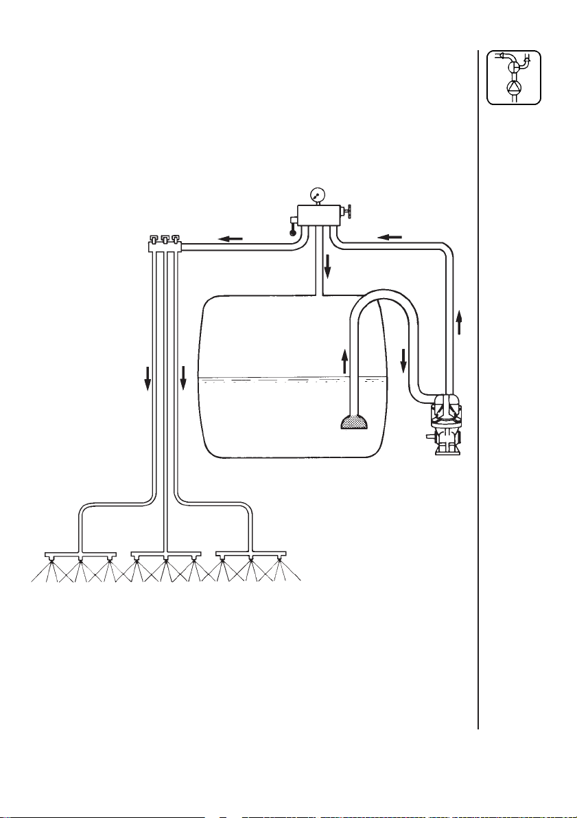
Operation diagram
1. Suction filter
2. Pump
3. On/off and pressure regulation valve
4. Distribution valve
5. Sprayer boom
4
3
1
2
5
5
Page 6
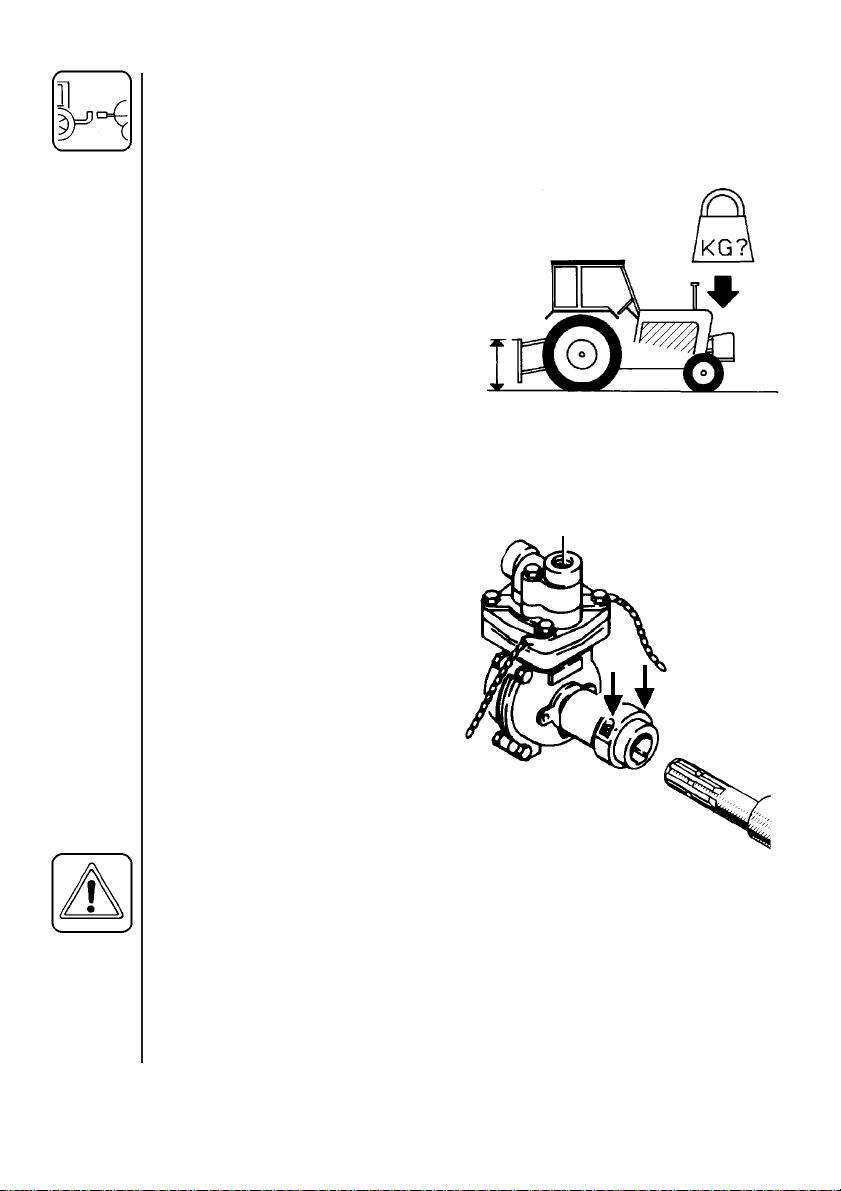
Connecting the sprayer
The sprayer is designed for three point suspension and is equipped
with 22 mm pivots (category I).
WARNING: Note the weight of the sprayer.
See section on Technical specifications.
Generally it is recommended to:
1. Add ballast to front of tractor.
2. Increase tyre pressure (see
tractor instruction book).
3. Travel at slower speeds when
driving with a full tank.
(The tractor will have decreased
braking efficiency.)
4. Be careful when filling/lifting the
sprayer the first time.
The pump is mounted directly
to the tractor P.T.O.
1. Undo the 2 allen screws * on
coupling and remove key.
2. Slide pump onto P.T.O.
shaft.
3. Replace key and tighten
allen screws.
4. Secure pump with supplied
chains to prevent rotation.
*
Roadworthyness
When driving on public roads and other areas where the highway code
applies, or areas where there are special rules and regulations for
marking and lights on implements, you should observe these and
equip implements accordingly.
6
Page 7

Operating instructions
T153-0006
Operation of the boom
Remove boom transport lock pin (8 metre
only). When unfolding (or folding) the initial
force to release the spring loaded breakaways will be higher than the actual unfolding/folding.
CAUTION: The breakaways must be
correctly tensioned and lubricated. (see
section on Re-adjustment of the boom)
Replace boom transport lock pin when
driving with folded boom.
Boom height
Correct boom height is very important in order to achieve the most
optimal spray pattern. (See Spray Technique book).
Small adjustments of the boom height can usually be made with the 3point suspension from the tractor - raising or lowering the sprayer.
In crops where greater adjustments are needed the boom height can
be changed manually by removing the 4 bolts holding the boom to the
frame.
Note: This is best done by 2 persons or with a mechanical hoist.
Pulsation damper
The air pressure in the pulsation damper is
preset at the factory to 2 bar. This covers spray
working pressures between 3 and 15 bar. When
using spray pressures outside this range, the air
pressure should be adjusted as shown in the
diagram. The diagram is also embossed on the
damper.
T020-0032
7
Page 8
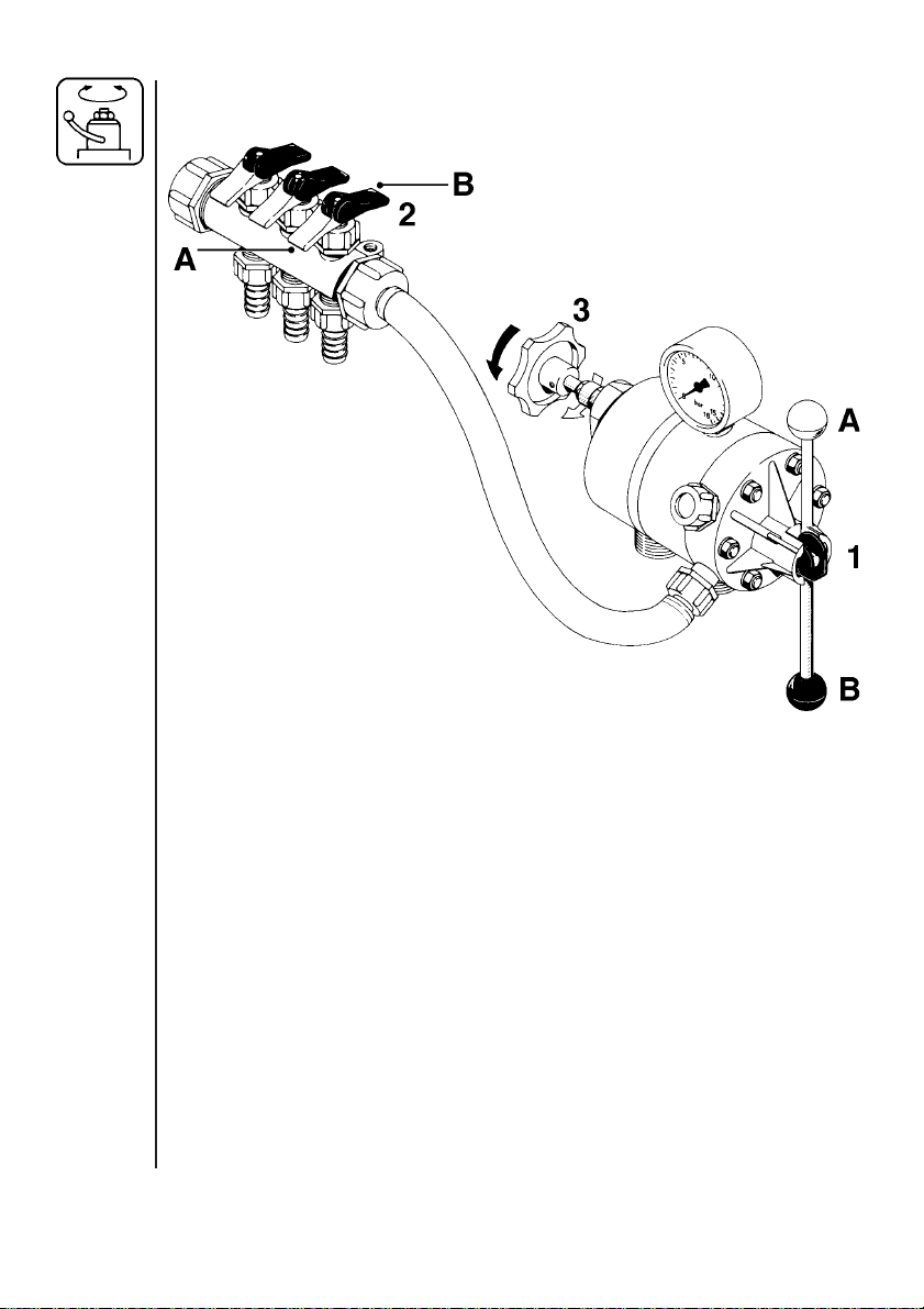
Adjustment of the operating unit
1. Turn main on/off handle (1) to off position A.
2. Set all hand levers on the distribution valve (2) to spraying position A.
3. Put the tractor in neutral and set the engine revolutions and thereby
the number of revolutions of the pump corresponding to the intended
travelling speed. Remember the number of revolutions on the P.T.O.
must be kept between 300-600 r/min.
4. Turn main on/off handle (1) to spraying position B.
5. Now turn the pressure regulating valve (3) to until the required
pressure is indicated on the pressure gauge.
6. Operating the control unit while driving:
To close the entire boom, turn the handle (1) to position A. This takes
the pressure off the pump. The liquid will then return to the tank via the
return system.
8
Page 9

The diaphragm anti-drip valves ensure instantaneous closing of all
nozzles. In order to close part of the boom, move lever (2) of the
distribution valve to position B (off position) for the section or sections
to be closed. Note that the pressure will rise and readjustment will be
necessary.
Drain valve operation
A drain valve cap is located under the tank. Unsrew it to drain tank. Be
careful not to loose the seal.
Maintenance
In order to derive full benefit from the sprayer for many years the
following few but important rules should be kept:
Cleaning the Sprayer - see Spray Technique book.
Filters
Clean filters ensure :
• Sprayer components such as valves, diaphragms and operating
unit are not hindered or damaged during operation.
• Nozzle blockages do not occur whilst spraying.
• Long life of pump. A blocked suction filter will result in pump cavita-
tion.
The main filter protecting sprayer components is the suction filter
inside the tank at the sump. Check it regularly.
Also regularly check nozzle filters.
9
Page 10

Lubrication
Recommended lubrication is shown in following tables. Use ball
bearing grease (lithium grease No.2)
NOTE: If the sprayers are cleaned with a high pressure cleaner or it
has been used to spray fertilizer, we recommend lubrication of the
entire machine.
2
Position on sprayer
Oil
Grease
Operation hours
Page to find
more information
10
Page 11
1X40
T201-0002
11
2X 20
3X 40
4X 40
8m SB
6
10
10
T213-0010
11
Page 12

Re-adjustment of the boom
After having used the sprayer for some days the boom should be
adjusted as follows:
When adjusting the sprayer must be on level ground with unfolded
boom.
Boom breakaway
The function of the breakaway is to prevent or reduce boom damage if
it should strike an object or the ground. If it is over-tight, it will not
function. If it is too loose, it will yawn (forward and back movement)
under spraying.
T103-0009
12
Lubricate coupling before adjusting spring tension. Slacken screw nut
A to decrease breakaway resistance. Do not overtighten; better to
loose than over-tight. Again minor adjustments in the field may be
necessary.
Ensure also channel bolts B are tight.
Outersection (8m SB)
C
The hindge should be firm.
If overtight it is difficult to fold.
To adjust, tighten or loosen nuts C.
T213-0010
Page 13

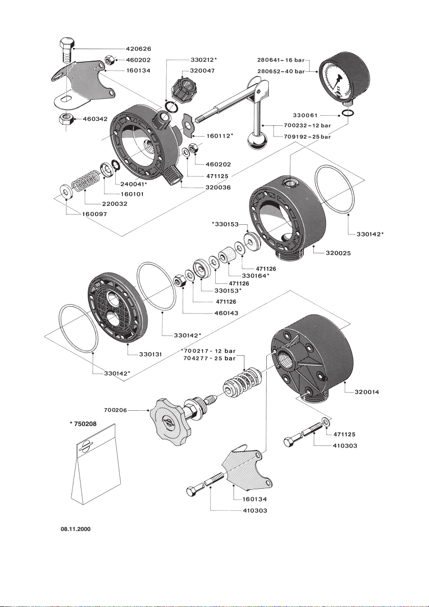
Changing of valves and diaphragms
Valves
Dismantle valve compartment (1). Before changing the valves (2) note
the orientation of the valves so that they may be replaced correctly.
It is recommended to use new gaskets (3) when changing or checking
the valves.
Diaphragms
Remove the diaphragm cover (4) after having dismantled the valve
compartment as indicated above. The diaphragm (5) may then be
changed. If fluids have reached the crankcase, re-grease the pump
thoroughly. Check also the drain hole at the bottom of the pump is not
blocked.
13
Page 14

Nozzle tubes and fittings
Poor seals are usually caused by;
• missing O-rings or gaskets
• damaged or incorrectly seated O-rings
• dry or deformed O-rings or gaskets
• foreign bodies
Therefore, in case of leaks: DO NOT over-tighten. Disassemble, check
condition and position of O-ring or gasket, clean lubricate and reassemble.
For radial connections only hand tighten them.
The O-ring must be lubricated ALL THE WAY ROUND before refitting.
14
For face connections, a little
mechanical leverage may be
used.
Off-season storage
When the spraying season is over you should devote some extra time
to the sprayer before it is stored.
Hoses
Check that none of the hoses are caught or have sharp bends.
A leaky hose can give an annoying delay in the middle of the spraying
job. Therefore check all the hoses and change if there is any doubt
about the durability.
Page 15
Paint
Some chemicals are very hard on paints. It is therefore well advised to
remove rust, if any, and then touch up the paint.
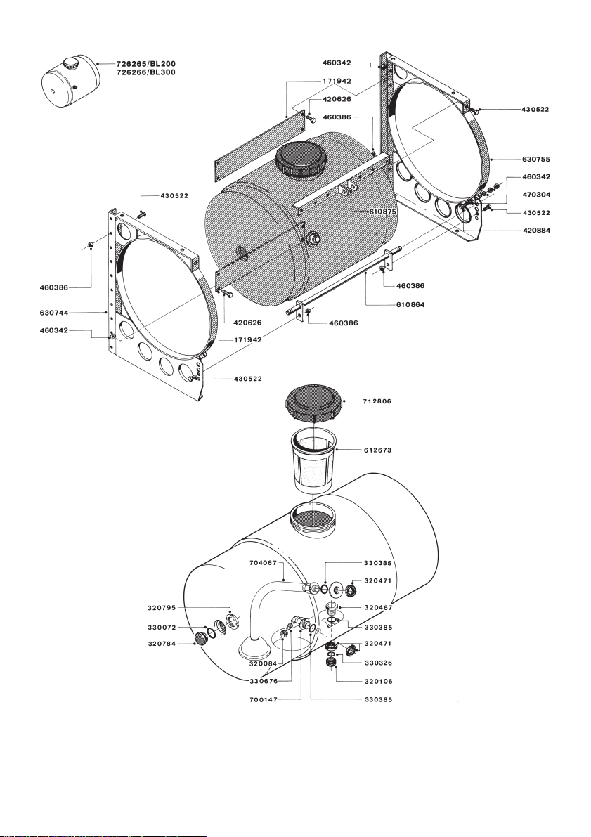
Tank
Check that no chemical residues are left from the last spraying. Chemical residues must not be left in the tank for a long time. It will reduce
the life of the tank. See Spray Technique book- Cleaning the sprayer.
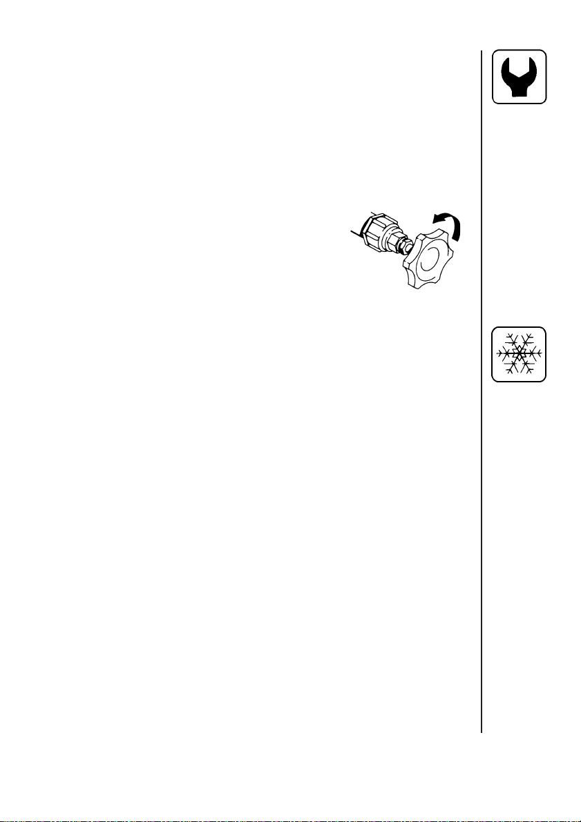
Operating unit
Take care that the pressure regulation valve is
completely loosened. The spring is thereby
relieved and operation difficulties are avoided at
starting-up next season.
Anti-freeze precaution
If the sprayer is not stored in a frost-proof place you should take the
following precautions: Put at least 5 litres of 33% anti-freeze mixture in
the tank and let the pump run a few minutes so that the entire system
including spray hose are filled. Remove the glycerine filled pressure
gauge and store it frost free in vertical position.
The anti-freeze solution also hinders the O-rings and gaskets from
drying out.
15
Page 16

Operational problems
In cases where breakdowns have occurred the same factors always
seem to come into play:
• Minor leaks on the suction side of the pump will reduce the pump
capacity or stop the suction completely.
• A clogged suction filter will hinder or prevent suction so that the
pump does not operate satisfactorily.
• Clogged up pressure filters will result in increasing pressure at the
pressure gauge but lower pressure at the nozzles.
• Foreign bodies stuck in the pump valves with the result that these
cannot close tightly against the valve seat. This reduces pump
efficiency.
• Poorly reassembled pumps, especially diaphragm covers will allow
the pump to suck air resulting in reduced or no capacity.
Therefore ALWAYS check:
1. Suction and nozzle filters are clean.
2. Hoses for leaks and cracks, paying particular attention to suction
hoses.
3. Gaskets and O-rings are present and in good condition.
4. Pressure gauge is in good working order. Correct dosage depends
on it.
5. Operating unit functions properly. Use clean water to check.
16
Page 17

Fault Probable cause Control / remedy
No spray from
blower when
turned on.
Lack of
pressure.
Pressure
dropping.
Pressure
increasing.
Formation of
foam.
Liquid leaks
from bottom of
pump.
Air leak on suction.
Air in system.
Suction / nozzle
filters clogged.
Incorrect assembly.
Pump valves blocked
or worn.
Defect pressure gauge.
Filters clogging.
Nozzles worn.
Tank is airtight.
Nozzle filters begin-
ning to clog.
Air is being sucked
into system.
Excessive liquid
agitation.
Damaged diaphragm.
Check suction tube and fittings.
Check tightness of pump diaphragm
and valve covers.
Fill suction hose with water for initial
prime.
Clean filters.
Recheck assembly.
Check for obstructions and wear.
Check for dirt at inlet of gauge.
Clean all filters. Fill with cleaner
water.
Check flow rate and replace nozzles
if it exceeds 10%.
Check vent is clear.
Clean all filters.
Check tightness / gaskets / O-rings
of all fittings on suction side.
Use foam damping additive.
Replace. See section Changing
valves and diaphragms.
17
Page 18
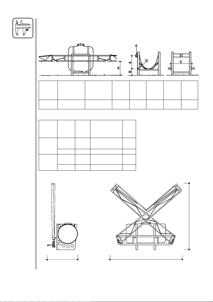
Technical specifications
Measure and weights
Tank Min. Max. ABCDE
size boom height boom height
l H mm H mm mm mm mm mm mm
200/300 20 595 520 210 588 22 26
Tank Spraying Pump Measure Weight
size width model a x b x c
lm cm kg
6 500 100 × 190 × 160 93
200 6 600 100 × 190 × 160 99
300 6 600 100 × 190 × 160 105
8 600 100 × 190 × 200 105
6 500 100 × 190 × 160 99
8 600 100 × 190 × 200 114
18
c
ba
Page 19

Power consumption and capacity
500/7.0
bar l/min kW l/min kW l/min kW l/min kW l/min kW
0 13 0,15 16 0,15 19 0,22 20 0,29 21 0,29
5 10 0,22 12 0,29 15 0,37 16 0,45 18 0,52
10 9 0,29 12 0,45 14 0,52 15 0,59 16 0,67
15
Rotation per min. r/min Capacity l/min Suction height 0,0 m
Power consumption kW Max. pressure 15 bar Weight 9,9 kg
600/7.0
bar l/min kW l/min kW l/min kW l/min kW l/min kW
0 19 0,15 28 0,22 38 0,29 41 0,30 46 0,37
5 17 0,29 23 0,45 28 0,52 30 0,59 34 0,67
10 17 0,45 22 0,59 28 0,82 30 0,89 33 0,97
15 16 21 27 30 33
Rotation per min. r/min Capacity l/min Suction height 0,0 m
Power consumption kW Max. pressure 15 bar Weight 15,6 kg
300 400 500 540 600
300 400 500 540 600
r/min
r/min
Filters and nozzles
Pos. Mesh/ Description/
colour nozzle
1
2 - 3
1 23 Suction filter
2 50 blue Nozzle 4110-16
3 50 blue Nozzle 4110-20
2 50 blue Nozzle 4110-14*
3 50 blue Nozzle 4110-16*
* 6m SB
19
Page 20
Pictorial symbols
Description
Function
Connection
Warning
Operating
Service/adjustment
Liquid flow
Pressure
20
Cleaning
Lubrication
Winter storage
Operational problems
Technical specifications
Page 21

Preassembly information
The sprayer is supplied ex-works in shipping packages (SP). Number
of SP’s per sprayer varies depending on model.
As this covers all BL models, please note the fittings covering exactly
your model.
NOTE:
Removal of the plastic bag covering the tank is easiest done before
assembly.
To verify connection of hoses, a function diagram is included on the
last page.
Packaging information
Materials used for packaging are environmentally compatible. They
can be safely deposited or they can be burnt in an incinerator.
Recycling
Cardboard: Can recycle up to 99% and therefore should be put into
the waste collection system.
Polystyrene foam: Can be recycled. Fluorocarbons (CFC) not used in
foam production.
Polyethylene: Can be recycled.
21
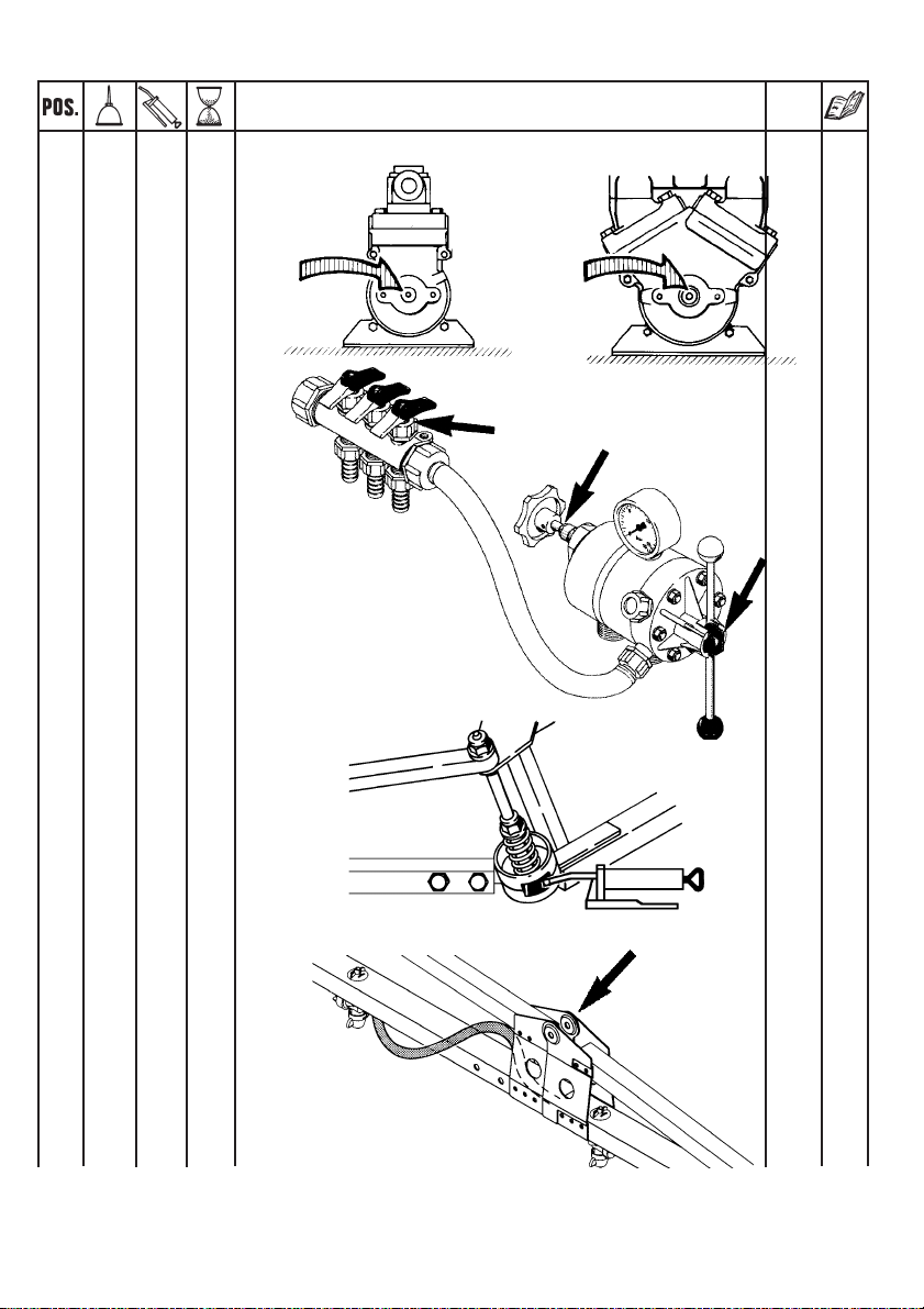
Page 22

Assembly
1. Fit pulsation damper and pressure hose B.
2. Fit suction damper and suction hose A.
NOTE: Use O-rings where indicated.
Lubricate them before assembly.
Where O-rings are not indicated,
use sealing tape.
3. Operating unit
and distribution
valve are assembled and bolted to
rack.
Screw pressure gauge
on to operating unit. Do not
overtighten. See back of
gauge.
Remember to pierce casing
after installation.
22
Page 23

4. Assemble tank and frame.
5. Fit hoses. Remember to lubricate O-rings before fitting.
A = Suction hose to pump.
B = From pump.
C = Return to tank.
F = Feed hoses to boom.
NOTE: For sake of good order, it may be necessary to shorten some hoses
(for example, suction hose A). This is best done when assembly is completed and before hoses are secured with plastic straps.
23
Page 24

6. Bolt angle brackets to
frame.
7. Fit boom centre.
8. Fit U-profile.
9. Fit boom wings. Be
cautious when folding
boom for the first time.
See section on boom
breakaway in instruction book.
T145-0010
6.
•
7.
•
•
9.
10. Nozzle tubes are
supplied with one lock
nozzle saddle per
tube. A. The rest can
slide lengthwise. B
allowing for extension
A B
and contraction.
•
8.
24
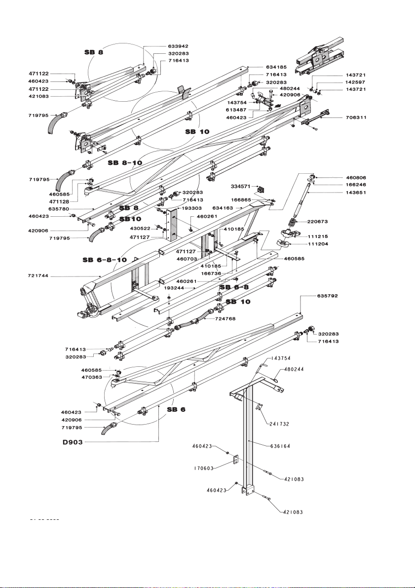
Page 25

Placement of nozzle tubes, connecting hoses and feed hoses.
REMEMBER: Lubricate O-rings before fitting.
T145-0011
T145-0011
F
F
11. Fit tubes using synthetic nut.
Press down 1, turn 2.
Do not overtighten.
12. Mount filter and COLOR TIPS.
8m SB
6m SB
T145-0012
13. For 8 metre SB - fit boom
transport lock. Arrow indicates forward direction of
travel.
25
Page 26

14. Check hose connections are
C
F
A
B
in accordance with diagram.
15. Organise hoses; it may be
necessary to shorten some of
them. Secure with straps.
26
Page 27

500 4-9.95 A1
27
Page 28

28
600 4.9.95 A5
Page 29
B5 15-5-79
29
Page 30

B6 18-2-91
30
Page 31

Dampers HJ73 30-9-93 B300
31
Page 32
32
SB 6/8/10m 18-2-91 D2
Page 33

33
Page 34
BL 200/300 18-2-91 E2
34
Page 35

Notes:
35
Page 36

Notes:
36
 Loading...