

Page 1
HARDI
AutoHeight
Original
Instruction book - SW 7(x)
67020400-110 - Version 1.10
GB - 01.2011
www.hardi-international.com
Page 2

We congratulate you for choosing a HARDI plant protection product. The reliability and
efficiency of this product depend upon your care. The first step is to carefully read and pay
attention to this instruction book. It contains essential information for the efficient use
and long life of this quality product.
Acknowledgements:
UC4+ and Roll Control are trademarks of NORAC Systems International Inc., Canada
NORAC® is a registered trademark of NORAC Systems International Inc., Canada
The original instruction book is approved and published in English. All other languages are translations of the
original. In the event of any conflicts, inaccuracies or deviations between the English original and other languages
the English version shall prevail.
Illustrations, technical information and data in this book are to the best of our belief correct at the time of printing.
As it is HARDI INTERNATIONAL A/S policy permanently to improve our products, we reserve the right to make
changes in design, features, accessories, specifications and maintenance instructions at any time and without
notice.
HARDI INTERNATIONAL A/S is without any obligation in relation to implements purchased before or after such
changes.
HARDI INTERNATIONAL A/S cannot undertake any responsibility for possible omissions or inaccuracies in this
publication, although everything possible has been done to make it complete and correct.
As this instruction book covers more models and features or equipment, which are available in certain countries
only, please pay attention to paragraphs dealing with precisely your model.
Published and printed by HARDI INTERNATIONAL A/S
Page 3

Table of Contents
1 - Declaration
This page is intentionally left blank ............................................................................................................................................................ 5
2 - Safety notes
Operator safety .....................................................................................................................................7
Precautions ................................................................................................................................................................................................................ 7
3 - Description
General info ...........................................................................................................................................9
Introduction .............................................................................................................................................................................................................. 9
Key features ............................................................................................................................................................................................................... 9
General description ........................................................................................................................................................................................... 10
Software .................................................................................................................................................................................................................... 10
Hardware components ................................................................................................................................................................................... 11
Understanding Your AutoHeight System ............................................................................................14
Understanding Performance Issues ........................................................................................................................................................ 14
Sensitivity (Sensi) Setting ............................................................................................................................................................................... 14
Boom Reaction Time ......................................................................................................................................................................................... 14
AutoHeight over Ditches, Waterways and Outside Rounds .................................................................................................... 14
Driving Through Ditches and Over Terraces ...................................................................................................................................... 15
Sensor Capabilities ............................................................................................................................................................................................. 15
Understanding Crop Mode And Soil Mode ........................................................................................................................................ 15
Areas of "No Crop" in CROP Mode ........................................................................................................................................................... 16
Thin Crop .................................................................................................................................................................................................................. 16
Boom Lift Sensor in Wheel Track ............................................................................................................................................................... 16
Sensing Further Ahead of the Boom ...................................................................................................................................................... 16
AutoHeight Sensor Capabilities and Limitations ............................................................................................................................ 17
Optional kits ........................................................................................................................................18
General info ............................................................................................................................................................................................................ 18
Severe Terrain Kit ................................................................................................................................................................................................. 18
Enhanced Stability Kit ....................................................................................................................................................................................... 18
Menu Structure .................................................................................................................................................................................................... 19
Full Menu Structure ........................................................................................................................................................................................... 20
Glossary ..................................................................................................................................................................................................................... 21
4 - System setup
System preparation .............................................................................................................................23
General info ............................................................................................................................................................................................................ 23
Automatic System Setup ............................................................................................................................................................................... 24
Retune ........................................................................................................................................................................................................................ 27
Manual System Setup ....................................................................................................................................................................................... 28
Setting Up Hydraulic Valves ......................................................................................................................................................................... 29
Quick Install ............................................................................................................................................................................................................. 34
Options ................................................................................................................................................35
HeadlandAssist ..................................................................................................................................................................................................... 35
5 - Operation
System operation ................................................................................................................................37
General info ............................................................................................................................................................................................................ 37
Power Up Sequence ......................................................................................................................................................................................... 37
Typical Operation ................................................................................................................................38
Basic operation ..................................................................................................................................................................................................... 38
Run screen ............................................................................................................................................................................................................... 38
Press & Hold Functions .................................................................................................................................................................................... 39
Changing between AUTOMATIC or MANUAL Mode ................................................................................................................... 39
Adjusting the Target Height (Setpoint) ................................................................................................................................................. 40
Viewing the Actual Boom Height ............................................................................................................................................................. 40
Sprayer switches .................................................................................................................................................................................................. 40
Changing the Sensitivity of the System ................................................................................................................................................ 40
3
Page 4

Table of Contents
Changing Between SOIL and CROP Mode .......................................................................................................................................... 41
Severe Terrain Mode ......................................................................................................................................................................................... 41
Changing the units ............................................................................................................................................................................................ 41
Options ................................................................................................................................................42
HeadlandAssist ..................................................................................................................................................................................................... 42
Remote Switches ................................................................................................................................................................................................. 43
Crop filter toggle ................................................................................................................................................................................................. 43
High Oil Temperature Alarm ........................................................................................................................................................................ 43
Sensor Reading Alarm ...................................................................................................................................................................................... 43
Minimum Height Mode .................................................................................................................................................................................. 44
Valve and Air Temperature ........................................................................................................................................................................... 44
Operational Messages ...................................................................................................................................................................................... 45
6 - Maintenance
Service info ..........................................................................................................................................47
General info ............................................................................................................................................................................................................ 47
Before each day of operation ...................................................................................................................................................................... 47
Sensor preparation and maintenance ................................................................................................................................................... 47
At the end of a season .................................................................................................................................................................................... 48
Lubrication of the sprayer .............................................................................................................................................................................. 49
7 - Fault finding
Operational problems .........................................................................................................................51
General info ............................................................................................................................................................................................................ 51
General operation ............................................................................................................................................................................................... 51
Setup Messages ................................................................................................................................................................................................... 52
Sensor Related Issues ........................................................................................................................................................................................ 53
Different cases of Sensor related issues are discussed below: ................................................................................................ 53
Sensor Swapping ................................................................................................................................................................................................ 53
Sensor Alignment ............................................................................................................................................................................................... 54
Hydraulic Related Issues ................................................................................................................................................................................. 55
Boom Stability ....................................................................................................................................................................................................... 56
8 - Technical specifications
Specifications ......................................................................................................................................57
Sprayer types ......................................................................................................................................................................................................... 57
9 - Index
Index ....................................................................................................................................................59
4
Page 5

This page is intentionally left blank
1 - Declaration
5
Page 6

1 - Declaration
6
Page 7

2 - Safety notes
Operator safety
This symbol means DANGER. Be very alert as your safety is involved!
€
This symbol means WARNING. Be alert as your safety can be involved!
±
This symbol means ATTENTION. This guides to better, easier and more safe operation of your sprayer!
μ
This symbol means NOTE.
÷
Precautions
Note the following recommended precautions and safe operating practices before using the sprayer and AutoHeight
system.
General info
Note the following recommended precautions and safe operating practices.
€
Read and understand this instruction book before using the equipment. It is equally important that other operators
€
of this equipment read and understand this book.
Keep children away from the equipment.
€
If any portion of this instruction book remains unclear after reading it, contact your HARDI dealer for further
€
explanation before using the equipment.
Turn electrical power off before connecting and disconnecting the display and transducers, servicing or using a
€
battery charger.
If an arc welder is used on the equipment or anything connected to the equipment, disconnect power leads before
€
welding.
Test sprayer with clean water prior to filling with chemicals.
€
Do not use a high pressure cleaner to clean the electronic components.
€
Operating AutoHeight
WARNING! Always ensure that the AutoHeight system is powered down or in MANUAL mode:
±
• Before leaving the operator's seat
• While the machine is not moving
• When transporting the machine
WARNING! Under no circumstances should any service work be performed on the machinery while the AutoHeight
±
system is in the AUTOMATIC mode.
WARNING! Before working on any part of the booms:
±
• Set the AutoHeight system to MANUAL mode
• Turn the sprayer engine off
7
Page 8

2 - Safety notes
ATTENTION! Do not operate this system before:
μ
• Reading and understanding the Operator’s Manual
• Thoroughly understanding your machine operation
NOTE! The AutoHeight system will greatly improve your spraying height accuracy and protect the boom against
÷
damage in a wide variety of field conditions. However, under some circumstances performance may be limited. The
OPERATOR of the sprayer must remain ALERT at all times and override the automatic control when necessary.
8
Page 9

3 - Description
General info
Introduction
Congratulations on your purchase of the HARDI AutoHeight system (UC4+ version). The system is manufactured with top
quality components and is engineered using the latest technology to provide operating features and reliability unmatched
for years to come.
When properly used, the AutoHeight system can provide protection from sprayer boom damage, improve sprayer
efficiency, and ensure chemicals are applied correctly.
This manual is intended to be used in conjunction with the:
• AutoHeight Installation Manual
• Sprayer Instruction Book
The manual provides a general description of the spray height control system, a section regarding system operation, and
discussion related to understanding performance issues. Also provided are instructions for the use of the control panel,
information regarding system setup, regular maintenance and troubleshooting.
Please take the time to read the complete instruction book before attempting to use the system. Although the AutoHeight
system has been designed for easy set-up and use, a thorough understanding of the information provided will ensure that
you receive the maximum benefit from the system.
Key features
The key features of the HARDI AutoHeight is:
Non-contact Sensing
• Sensing is done using ultrasonic sensors which means no parts of the HARDI AutoHeight system come in contact with
the ground.
• Using a non-contact system means there will be no additional forces put on the boom, which could cause damage to
the sprayer boom.
Automatic Software Setup
• The system completes an automatic system setup, which calibrates the software specifically for the sprayer.
• This provides the maximum performance for the height control system.
Individual Boom Overrides
• When necessary one boom section can be put into manual mode to avoid an obstacle, while the other boom sections
stay in automatic.
• This can take the stress out of spraying along obstacles such as fences because you only have to watch the boom along
the obstacle, knowing that the HARDI AutoHeight system is maintaining the height on the rest of the boom sections.
Smart Sensor Technology
• All sensors are designed specifically for the agricultural industry.
9
Page 10
3 - Description
General description
Figure 1 - System Components and General Location
A. Control Panel
B. Power Cable
C. Extension and Trunk Cables
D. AutoHeight Valve
E. Roll Sensors
F. Boom lift Sensor
G. Left Outer Sensor
H. Optional Left Inner Sensor
I. Optional Right Inner Sensor
J. Right Outer Sensor
NOTE! Some kits may not include all of the components shown.
÷
For more information on each component, please refer to the AutoHeight Installation Manual.
μ
Software
The information in this manual applies to systems with Version 7 AutoHeight panel software. When the panel is turned on,
the software version and revision will be displayed for a few seconds as described in “Power Up Sequence” on page 37.
All AutoHeight panels can have their software upgraded. It is recommended that all panels with earlier software are updated
to the current software version. Contact your local dealer or HARDI for more information.
10
Page 11
3 - Description
Figure 2 - AutoHeight Sensor and Mounting Bracket
Hardware components
The components of the HARDI AutoHeight are:
Cables
The system will function properly with a power supply between 12 and 28 volts and may draw up to 10 amperes during
normal operation.
The AutoHeight panel contains intelligent valve drive circuitry that helps to protect the sprayer's system against short
circuits and other wiring problems. However, it is still recommended to connect the AutoHeight power cable to a fused
supply that turns on and off with the ignition key of the sprayer/tractor. For more information on cables, please see the
AutoHeight Installation Manual.
Sensors
Three sensors are provided with your AutoHeight boom control kit. The
sensors use an ultrasonic signal to measure the distance to the ground,
or the top of the crop. Three sensors are required to provide good
overall height management of the boom. Two sensors are mounted on
the outer sections of each wing (Figure 2). These sensors maintain each
wing at the set target height independently.
The third sensor is mounted on the centre section. The boom lift sensor
is useful for setting your initial spray height when you begin spraying in
a field.
It is true that the centre section height will not change much, in
consistent soil conditions, since both ends of the centre section follow
the height of the power unit. However, it is extremely difficult to judge
the boom's actual height accurately from the cab. It is also very difficult
for the operator to see the main section nozzles. It is common for
operators to be in error from 20 to 30 cm or more. The AutoHeight panel will give you an actual height reading in the cab
and allow active control to the desired height.
The reason for the centre section sensor is that soil conditions change along with the weight of the machine. As the sprayer
tank fluid level changes throughout the day and soil conditions vary, the centre section height will change because of the
amount the tires sink into the soil.
Special attention must be taken into consideration when mounting the centre section sensor, as explained in the
AutoHeight Installation Manual for your sprayer.
The ultrasonic sensors are designed to work best in the brackets provided (Figure 2). If you decide to use a different style of
sensor mount, you may limit the performance of the sensor and/or void your warranty. Further, it is important to follow the
guidelines in the AutoHeight Installation Manual for mounting the sensors. The sensors should be at least 25 cm above and
25 cm in front of the spray nozzles.
For large boom or severe terrain applications, an additional sensor may be mounted near the midpoint of each boom to
obtain an average height reading. The average height reading will provide improved height control over the length of the
boom and protect the boom in severe terrain conditions. See “Figure 3 - Severe Terrain - Additional Sensors Required” on
page 12.
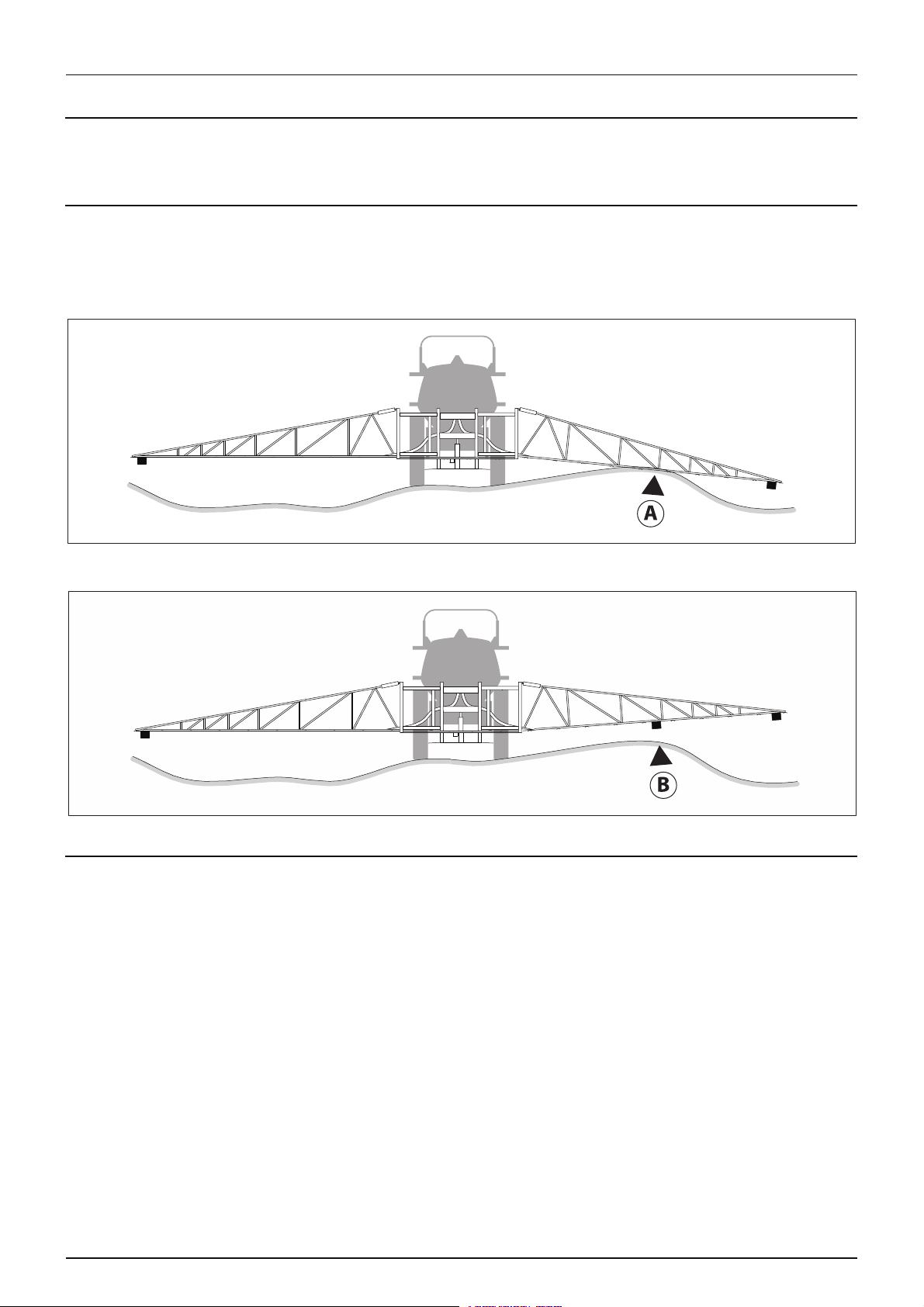
A. Possible crash without additional sensors
11
Page 12
3 - Description
B. Crash avoided with additional sensors
Figure 3 - Severe Terrain - Additional Sensors Required
The centre section sensor can also be used to adjust the slant angle of the entire boom. Alternatively, slant sensors can also
be used to adjust the main slant angle of the entire boom. Addition of this sensor to the AutoHeight system can greatly
improve the speed and stability of the automatic control actions.
Figure 4 - Slant Control of the Main Frame
Height Sensors
• Height sensors use an ultrasonic signal to measure distance to the ground or crop canopy.
• Normally there are three height sensors used, but a system may have as many as 6 sensors. A sensor is mounted to the
outer part of each boom tip, and another sensor is mounted to the centre section.
Roll Sensors
• Roll sensors are important for measuring boom and sprayer roll dynamics.
• Two roll sensors are normally used for a UC4+ Spray Height Control System.
• The mounting position of the roll sensors varies from sprayer to sprayer depending on boom geometry and
suspension.
12
Page 13
3 - Description
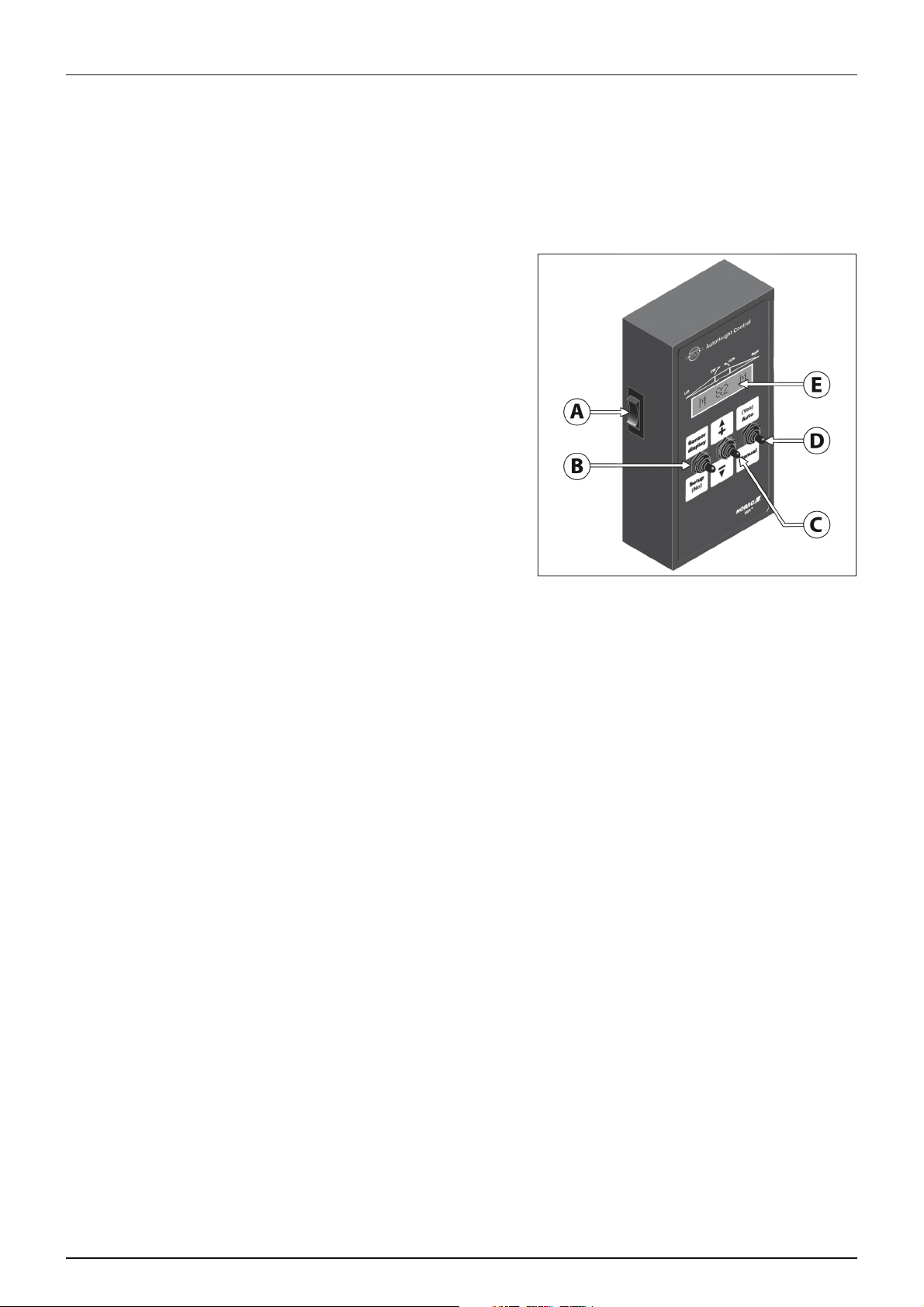
Figure 5 - AutoHeight Panel
Control Panel
The AutoHeight panel (Figure 5) is the main component of the AutoHeight system. The control panel uses the readings from
the ultrasonic sensors to control solenoid operated valves that in turn adjust the boom height. The control panel will:
• Indicate when the system is in AUTOMATIC or MANUAL mode.
• Indicate any hydraulic action which is underway.
• Accept input to adjust all control system settings.
Control panel functions are:
A. Power Switch
B. Sensor Display/Setup Switch (No)
C. +/- Switch (Up/Down)
D. Auto/Manual Switch (Yes)
E. LCD Screen
13
Page 14

3 - Description
Understanding Your AutoHeight System
Understanding Performance Issues
Your AutoHeight will work well in most situations. However, as with any equipment, it is important that the operator remains
alert at all times. There may be some field and terrain situations where performance is diminished. In these situations the
operator must resume height control of the booms manually. A discussion of performance issues is given below to help
clarify these situations.
Sensitivity (Sensi) Setting
The AutoHeight system is configured to work well in most conditions, with warm hydraulic oil, at a sensitivity (Sensi)
setting of five. When you first begin operation at the start of a day, it may be necessary to operate at a higher sensitivity until
the oil has reached normal temperature. After warmup, keep decreasing the Sensi setting until the performance is
optimized, to avoid overheating of the hydraulic oil.
Different types of terrain may require different Sensi settings. The Sensi setting controls more than just response
time. It also determines how accurately the AutoHeight system will try to correct for height errors. The higher the sensitivity
the higher the accuracy. At low sensitivity, a few cm of error will be tolerated. At high sensitivity, virtually no error will be
tolerated. Therefore, the system will be much more active at high sensitivity than at low sensitivity.
NOTE! Running AutoHeight at high sensitivity will increase heat build-up of the oil. Specially when AutoHeight
÷
system is used with tractors that have an open centre system without load sensing, it may require lower sensitivity
settings to avoid overheating of hydraulic oil. See “Hydraulic hook-up” on page 23.
NOTE! Field conditions and operator preferences determine the appropriate Sensi setting.
÷
Boom Reaction Time
There are two key factors that determine how quickly your boom can react to changes in terrain. The first factor is the
available hydraulic speed. The maximum hydraulic speed of your boom was designed by the sprayer manufacturer and is
not improved or diminished with the addition of the AutoHeight height control system.
The second factor is the mechanical design of the sprayer. The Sensi setting does affect the reaction time of your boom
- the higher the number the quicker the response. However, how high you can run the Sensi setting is determined to a
large extent by mechanical issues related to the boom and sprayer.
Important design issues include the style of boom mount (for example, centre pivot or nonparallel links), the amount of
mechanical damping and spring centring on the boom lift mount, and whether a boom slant system is available on the
sprayer. All of these factors together determine the maximum Sensi setting you can run on your AutoHeight system.
This, in turn, will set the reaction time of the boom in a given situation.
The AutoHeight electronics are rarely the limiting factor in determining overall automatic height control performance.
AutoHeight over Ditches, Waterways and Outside Rounds
Many situations exist where one sensor may be reading over terrain that does not accurately reflect the situation for the rest
of the boom. For example, if you are spraying along a waterway, it may be necessary to run the outer boom sensor out into
the waterway itself. This situation is similar to the picture in “Figure 3 - Severe Terrain - Additional Sensors Required” on
page 12. In this example, the outer sensor will bring the boom lower than desired and may put the mid-point of the boom
at risk. Outside rounds adjacent to very weedy areas or tall thick grass are examples of the opposite situation.
In these situations the operator must remain alert and override A UTO m ode when nece ssa ry. A ddit ion of th e opt ion al se vere
terrain (inner) sensors will greatly improve performance in these situations.
WARNING! In most countries spraying over ditches and waterways is strictly prohibited! Always follow local
±
legislation!
14
Page 15

3 - Description
Driving Through Ditches and Over Terraces
Changes in terrain that include driving over terraces or through ditches are special performance cases. This type of terrain
can cause the sprayer to pitch and roll significantly. Sprayer operation at speeds of 15-30 km/h in severe terrain may result
in rapid changes in boom tip height. In these situations, typical sprayer hydraulic systems are not capable of tip speeds high
enough to correct for the induced error.
The sprayer’s roll control system will compensate for the sprayer roll in this situation and also add stability to your boom in
normal operating conditions.
Alternative solution is for the operator to recognize these situations before they occur and manually raise the boom
section(s) to a safe height. To return to AUTO mode, use the "AUTO (YES)" switch.
Sensor Capabilities
In order for the AutoHeight system to work at its maximum level of performance, the AutoHeight sensors must be returning
accurate height readings at the designed frequency. Under typical conditions, the sensors can provide accurate height
readings from 0.2 to over 3.0 m and return many height readings in one second. The target in SOIL mode can be identified
through stubble, young crops, row crops, and normal trash. The target in CROP mode can be identified over cereal grains,
specialty crops, and row crops. See the next section for more information on CROP and SOIL mode guidelines.
There are two main steps to ensure sensor performance. The first step is proper mounting. See “Hardware components” on
page 11 for more information on sensor mounting. The second step is to ensure that the protective foam covers on the
sensors are kept clean, and that the ultrasonic transducer behind the foam does not become corroded or excessively dirty.
Extra foam pieces are shipped with your kit. The transducer is a maintenance item and can be replaced at HARDI service
locations. Transducers can last up to ten years, depending on conditions. Refer to “6 - Maintenance” on page 47 for more
maintenance information.
If the mouth of the sensor becomes wet, it is normal for the sensor to return error messages until the transducer has dried
off. This could include rain or excessive overspray. Material ca n build up on the transducer if the s ensor is mo unted to o close
to the spray nozzles. This is the reason that the sensor must be mounted at least 25 cm in front of the nozzles. It keeps the
sensor housing out of the normal region of overspray.
In the sprayer boom application, the sensors ignore any target that is closer than 25 cm from the bottom of the sensor
housing. This region is called the blanking range. Operating the sensor at heights near the blanking range is dangerous and
will affect performance because height readings can be very intermittent. This is the reason that each sensor must be
mounted at least 25 cm above the spray nozzles.
Understanding Crop Mode And Soil Mode
A unique feature of AutoHeight sensors is their ability to operate in CROP mode. In this mode the sensor will track the first
available sonic target. That is, when positioned over standing crop, the sensor will return the average height of the heads in
a circular area below the sensor. In the same situation in SOIL mode, the sensor will track the last available sonic target. That
is, signals from the heads, leaves, and trash will be ignored in favor of the ground.
It is important to note that the targets must be available and of sufficient strength for the sensor to "see" them. There may
be some crop and terrain situations that do not work well for CROP mode or SOIL mode. In these situations the operator
must resume height control of the booms manually.
In general, the addition of the severe terrain kit will improve performance in CROP mode. All of the situations discussed
below are lessened by the addition of the extra sensors on the wings.
15
Page 16
3 - Description
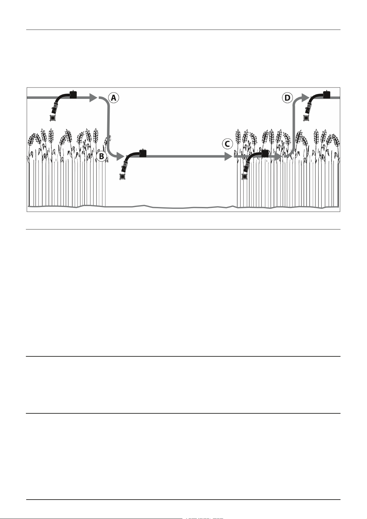
Areas of "No Crop" in CROP Mode
If, while operating in CROP mode, the sensor encounters an area where there is no crop, the system will behave as follows.
The sensor will track the soil (A) because only one target is available. The boom will lower (B) as no crop is detected. Areas
like this may include missed areas during seeding, alkaline areas, and so on. When the problem area ends (C), it may not be
possible for the sensor to see the crop again unless the operator raises the boom manually. The sensor may be closer than
required 25 cm from heads of the crop (D), thus blanking out the desired target.
Figure 8 - Area of "No Crop" When Operating CROP Mode
Thin Crop
The AutoHeight ultrasonic sensors operate by bouncing sound waves off the desired target. A minimum signal level is
required from the crop in order to use it for control purposes. This is no different than the fact that your radio must be at a
certain minimum volume level before you can physically hear it. Different types of crop and crops at different stages of
development return varying levels of sound. The following are some general guidelines.
• Crops in growing stages are relatively good sonic targets.
• Bearded crops are relatively poor sonic targets.
• In row crops, the sensor must be positioned over the row to use the crop signal, or between the rows to use the
ground signal.
• The desired target must cover roughly 60 percent of the area to be tracked consistently. That is, when looking at the
ground, the heads should cover about 60 percent of the ground. Otherwise, you can use SOIL mode.
• If the sensor runs too close to the heads, they may not return enough signal to be seen, or they may be blanked out.
The nozzles must be at least 55 cm from the crop. Slightly higher target height settings will work better in thin crop.
Boom Lift Sensor in Wheel Track
The required location for the centre section sensor is determined by the AutoHeight Installation Manual for your sprayer and
by the options you have installed. Special attention is necessary when mounting the centre section sensor. Mounting the
centre section sensor directly behind a sprayer tire may impair boom lift control when operating in CROP mode. Height
readings from crop that is flattened by the sprayer wheel do not provide an accurate measurement of canopy height,
resulting in poor performance.
Sensing Further Ahead of the Boom
A common misconception is moving the sensor further ahead of the boom will increase performance. Moving the sensor
further ahead of the boom increases the distance between the nozzle and sensor. This puts the sensor at a different location
within the field than the nozzles, which introduces a height error at the nozzles. In severe terrain this height error can bring
the nozzles close to the ground as the sensor reads over the crest of the hill or down a ditch.
Similarly, aiming the sensors ahead (rather than pointing straight down) will reduce sensor performance by providing
inaccurate height readings.
16
Page 17

3 - Description
AutoHeight Sensor Capabilities and Limitations
The AutoHeight sensors are designed and built specifically for agricultural purposes. However, the ultrasonic transducer
must be clean and dry for optimal performance. The foam disc fitted into the bottom of the sensor protects the transducer
from dust. If the protective foams become wet (from rain, drift from the spray nozzles etc.) the sensors may have trouble
reading.
The height sensors will provide height readings from 22 to 300 cm, under typical conditions. In order to optimize sensor
performance, the AutoHeight sensor has a minimum distance that it will read (also known as the blanking range). As a result,
the AutoHeight sensor is designed to ignore targets closer than 20 cm from the bottom of the sensor housing.
17
Page 18
3 - Description
Optional kits
General info
The kits shown below are optional add on kits for the UC4+ Spray Height Controller. These kits will help improve the
performance for certain situations described below.
Severe Terrain Kit
• Additional sensors may be added to improve boom protection and system performance.
• More suitable for larger booms and in severe terrain conditions.
A. Possible chrash without additional sensors.
B. Chrash avoided with additional sensor.
Enhanced Stability Kit
• This kit is designed to provide enhanced boom stability for sprayers which are loosely coupled between the
intermediate frame (paralift arms) and the sprayer chassis.
• The roll sensor included in this kit will provide an additional measurement of the sprayer dynamics to allow for greater
stability of the boom.
18
Page 19

Menu Structure
Navigating past the end of the menu will return the control panel to the run screen
More?
88 () 67
56
55 55
55 55
M
55
Sensi 5
Soil ON
ReTune?
More?
Navigating past the end of the menu will return the control panel to the run screen
Toggle the "AUTO (YES)" switch to edit or view more sensor settings.
Displays diagnostics information used by technical staff.
Displays the current boom lift height, in the selected units.
Displays the current right boom heights, in the selected units, from left to right.
Displays the current left boom heights, in the selected units, from left to right.
SENSOR DISPLAY Menu
M
Displays the current control sensitivity (Sensi) setting. A higher number results in a quicker response. Range is from 1 to 10.
Use the "+/-" switch to set the sensor target to SOIL or CROP mode.
The ReTune will optimize your system for the best performance possible. This will take from one to three minutes. (Section 6.2). The
menu retunes Dead Zone (DZ) and Valve Gain (KP) - not for sensor problems.
Toggle the "AUTO (YES) " switch to edit or view more control settings.
SENSOR DISPLAY / SETUP (NO) Switch
SETUP Menu
3 - Description
The run screen is usually displayed. If no switch is toggled for 30
seconds, the LCD will revert to this screen. Also, from any menu
prompt, if you toggle and hold the "SETUP (NO)" switch for two
seconds, the control panel will return to this screen. The heigh ts are
adjusted for the offset between the sensor and nozzles.
Table 1 - Main Menu Structure
19
Page 20

3 - Description
MHM SP
MHS 18
MHC 25
Units cm
“Adjusting the
Target Height
(Setpoint)” on
page 40
RF off
IF off
BFh- 215
BF 2080
MLht 27
ML 3567
“Setting Up
Sensors” on
page 28
RIht 30
RI 3571
ROht 32
RO 11070
“Setting Up
Sensors” on
page 28
LIht 28
LI 3569
LOht31
LO 11069
“Setting Up
Sensors” on
page 28
Other ?
Roll ?
Main ?
Right ?
Left ?
More ?
66 () 58
55 “Viewing the Actual Boom Height” on page 40
55 56
55 55
Left ?
Right ?
Rems On
Install?
“Au to ma tic
System Setup”
on page 24
Roll Off
DZ 20
KP 175
DZ 20
KP 150
“Setting Up
Hydraulic
Valves” on
page 29
Main On
DZ 10
KP 50
DZ 5
KP 50
“Setting Up
Hydraulic
Valves” on
page 29
Rght On
-DZ 103
-KP 49
-DZ 99
-KP 35
“Setting Up
Hydraulic
Valves” on
page 29
Left On
DZ- 100
KP- 50
DZ- 105
KP- 37
“Setting Up
Hydraulic
Valves” on
page 29
M 55 M “Power Up Sequence” on page 37
Sensi 5 “Changing the Sensitivity of the System” on page 40
Soil On “Changing Between SOIL and CROP Mode” on page 41
ReTune “Retune” on page 27
More ?
Main ?
Roll ?
Other ?
Full Menu Structure
Tab le 2
20
Page 21

3 - Description
Glossary
The following is a list of abbreviations used in the HARDI AutoHeight. Some abbreviations are combined in different display
views.
Abbreviation Explanation
AAutomatic
Absent Failure message
Alrm Alarm
AT Ai r Tem per at ure
BF Boom Frame
Dfalting Resetting the panel
DZ Valve Dead Zone
h = ht Height
IF Intermediate Frame
KP Valve Gain
LEV Levelling
LftDft Left Detection
LI Left Inner (sensor)
LO Left Outer (sensor)
MManual
MHC Minimum Height Crop Mode
MHM Minimum Height Mode
MHS Minimum Height Soil Mode
ML Boom Lift sensor (Main Lift sensor)
MlfDet Boom lift Detection
Mot’n Dly Motion Delay
NC No Communication
NoRdg = NR No Reading
Rems Remote Switches
RF Reference Frame
Rght Right
RI Right Inner (sensor)
RO Right Outer (sensor)
Sensi Sensitivity
SN Serial Number
SNR Sensor
SP Set Point
Stp Step
VT Valve Block Temperature
21
Page 22

3 - Description
22
Page 23

4 - System setup
System preparation
General info
Before the AutoHeight boom height control system will function properly, some information about the sprayer, tractor and
connected sensors is necessary.
Hydraulic hook-up
Tractors vary in design regarding the hydraulic system - either constant flow (open centre) systems or variable flow (closed
centre) systems. The open centre hydraulics block needs to be set for the system the tractor uses, whether open centre
hydraulics or closed centre variable system with load sensing will be used.
NOTE! It is strongly recommended to use a tractor with a closed center or load sensing variable hydraulic system in
÷
combination with the AutoHeight boom height control system, as an open centre system without load sensing may
heat the oil excessively.
NOTE! Running AutoHeight at high sensitivity will increase heat build-up of the oil. Specially when AutoHeight
÷
system is used with tractors that has an open centre system without load sensing, it may require lower sensitivity
settings to avoid overheating of hydraulic oil.
The valve (1) on the side of the block is factory set for open centre
hydraulics, but if closed centre hydraulics will be used (also in
combination with load sensing) then screw in the valve.
Certain tractor models are able to use Load Sensing without connecting
an external sensing line. But if optimal sensing control pressure cannot
be obtained, an external sensing line needs to be mounted (3). Please
consult your tractor dealer for correct setup and correct connection.
Before operating the hydraulics, the valve should be adjusted according
to the specific tractor model. If you are unsure of the type of hydraulic
system of your tractor, please consult your tractor dealer.
Schedule with combinations of settings for flow element and circuit
value:
Valve no. 1 2 3 ( LS port)
Open centre Out Out Not connected
Closed centre In In Not connected
Load sensing (LS) In Out* Connected
*if tractor requires pressure relief, contact your tractor dealer for further advice.
WARNING! Always be sure to fully extract or retract the open/closed centre selection valve (1). Failure to do so may
±
cause damage to vital pump parts.
WARNING! It is of essential importance that connectors on the sensing line are kept totally clean. Failure to do so may
±
result in impurities entering the pump and thereby causing damage to vital pump parts.
Control panel
When the control panel is turned on for the first time, the AutoHeight panel guides the operator through the Automatic
System Setup (This is normally done by your HARDI dealer). This procedure is described in “Automatic System Setup” on
page 24. Normally the AutoHeight system will automatically configure and calibrate itself to the sprayer. If this process does
not produce the desired results, perform Manual System Setup described in “Manual System Setup” on page 28. From time
to time it may be necessary to ReTune the AutoHeight electronics to your sprayer's hydraulics. This procedure is described
in “Retune” on page 27.
23
Page 24

4 - System setup
Automatic System Setup
The first time the AutoHeight system is powered up, it will guide you through the Automatic System Setup to customize the
AutoHeight settings to your sprayer (This is normally done by your HARDI dealer). The entire procedure should take
approximately two to seven minutes.
At any point during the setup procedure, you can exit by toggling the "SETUP (NO)" switch. However, if you exit without
completing the System Setup, you may not be able to use the AutoHeight in AUTO mode.
If you wish to restart/rerun this procedure after an initial setup has been completed, navigate to the "Install?" prompt
in the SETUP menu and confirm the action with the "AUTO (YES)" switch.
DANGER! At points during the system setup (retune) all boom sections need to move. Personnel and equipment
€
must be clear of all boom sections, and unless instructed, do NOT leave the tractor’s seat while performing a system
setup. Keep an eye to the control panel and prepare to toggle the "SETUP (NO)" switch to stop setup procedure, if
persons get into of the boom!
WARNING! Make sure all booms have room to lift fully and are clear of power lines.
±
NOTE! If you confirm the "Install?" menu prompt by accident, you can exit by toggling "SETUP (NO)" before
÷
confirming a sprayer type. No settings will be lost. However, if you confirm a sprayer type and the "Dfalting"
message (STEP 4 in “STEP 5: Select the Sprayer Type” on page 25) appears, all previous system settings will be lost.
You may need to perform Automatic System Setup again.
STEP 1: Prepare the Equipment
• Unfold the sprayer in a location that is relatively level, and where the sensors are over bare soil or gravel.
NOTE! Do not conduct the System Setup or ReTune procedure over standing crop or tall weeds/grass. Avoid concrete
÷
or asphalt surfaces.
STEP 2: Prepare the Equipment
Properly tuned suspension systems will optimize AutoHeight performance, especially on roll-bias (active roll) systems.
• Ensure all hydraulic boom functions are operating properly:
• All fold functions.
• Main lift function.
• Wing tilt function.
•Slant function.
• Ensure the boom guide-rods are set to the “tapered” position, i.e. more stable.
• Check the pads between the sprayer boom and the boom carrier frame to ensure no friction because of wear. Use
grease or other lubricants, if necessary. This is important and will increase the AutoHeight system performance
significantly.
• Ensure boom suspension is critically damped, which is illustrated
as tip height (H) movement over time (T ) when doing following:
A. Unlock the pendulum, and push boom tip down
approximately 75 cm.
B. Hold the boom steady for a moment, and release.
C. Ensure the boom returns to its relaxed state as quickly as
possible, with little to no overshoot.
Adjust the boom damper accordingly.
STEP 3: Prepare the Equipment
• Start the tractor hydraulic oil supply and run the sprayer's engine
at a normal working RPM for the entire setup.
Make sure that you can manually adjust the height of all your boom sections. If your manual controls do not work
normally, check the AutoHeight Installation Manual that came with your kit for troubleshooting information.
24
Page 25

4 - System setup
Type +/-Select
HD4?
Dfalting
3 Sensrs
booms atLevel height90 cm Proceed?
AUTOHold Doneuntil
SwitchRelease
ATTENTION! For best results, the hydraulic system should be under a normal load and at a normal working
μ
temperature. An effective way to warm the oil is to cycle all boom sections up and down manually for 5 minutes.
Longer warm up times may be required in cold weather. Ensure any hydraulic flow controls are adjusted for normal
field operation.
NOTE! Changing the flow controls during or after System Setup will affect AutoHeight operation.
÷
STEP 4: Turn On the AutoHeight Panel
• If this is the first setup for the panel, this process will begin automatically. If the panel was previously setup, you need
to select "Install?" from the SETUP menu to initiate Automatic System Setup.
NOTE! If other messages appear on the LCD screen during the following steps, refer to “Retune” on page 27 for more
÷
information.
STEP 5: Select the Sprayer Type
• Use the "+/-" switch to toggle through a list of available sprayer
types. The types are listed in “Specifications” on page 57.
• When the desired type is shown, confirm the selection with the
"AUTO (YES)" switch.
• If you wish to exit the install now before changing any settings,
toggle the "SETUP (NO)" switch.
• The control panel is loading all the settings for your sprayer.
STEP 6: Sensor Detect
• The control panel reads the serial numbers of all connected sensors.
• Number of sensors found is displayed. This should match the
number of sensors on your system. If it does not, turn off the
control panel and ensure that all sensors are plugged in and
operating.
• If you have boom slant control, manually level the boom.
• Position all other boom sections such that the nozzles are 90 cm from the ground.
NOTE! If you cannot get all the booms set to exactly 90 cm, you can adjust the sensor height after you have finished
÷
the install. Refer to “Calibrating the Sensor's Height Reading (Zero Height)” on page 29 for more details.
• Toggle "AUTO (YES)" to continue.
• Hold the "AUTO (YES)" switch to begin the sensor detect sequence. During the procedure you must hold the "AUTO
(YES)" switch. If "AUTO (YES)" is released, simply toggle and hold again to continue the procedure.
• The control panel will automatically slot in the sensors to the correct locations and indicate the progress.
• Release the "AUTO (YES)" switch to continue.
25
Page 26

4 - System setup
boom tippush
& let goground
Exit cab
near to
AUTOHold Doneuntil
Done
M 84 M
A 115 A
STEP 7: Boom Geometry Tuning
NOTE! Do not activate any hydraulic functions during this step.
÷
• Exit the cab of the machine and manually
push either boom tip near to the ground
or at least 40 cm for a moment and then
let go.
WARNING! Do not walk near the sensors when approaching the boom. Stay at least 1 metre from the sensor in order
±
not to induce measurement error.
STEP 8: Hydraulic Tuning
• Hold the "AUTO (YES)" switch to continue the hydraulic tuning. If "AUTO (YES)" is released before "Done" is displayed,
simply toggle and hold again to continue the procedure.
• The panel will display various messages as it is working. The messages are displayed for informational purposes only.
• Release the "AUTO (YES)" switch, the hydraulic tuning is complete.
STEP 9: Control System Test
• Run screen shown. It shows the system in manual mode with an
average height reading of 84 cm.
WARNING! In the following procedure, switch the control panel
±
to manual mode immediately if the boom movements are
erratic.
• Toggle "AUTO (YES)" to start AUTO mode. Observe the behaviour of the booms while correcting to the target height.
• The operating screen shows the system is in AUTO mode and the
target height is 115 cm.
ATTENTION! The boom movements should be smooth and stable. Boom corrections should stop after a few seconds,
μ
under normal conditions (excessive wind may cause small corrections to continue).
• Toggle the "MANUAL" switch to return to MANUAL mode. If the boom corrections are done in an acceptable manner,
your system is ready to use.
Automatic System Setup Complete!
26
Page 27

4 - System setup
Retune
From time to time it may be necessary to recalibrate (Retune) the AutoHeight electronics to your sprayer's hydraulics.
Examples of such times are:
• When a hydraulic solenoid valve is changed
• When the hydraulic pump is changed or adjusted
• A different tractor has been connected to the sprayer.
• The tractor’s hydraulic flow control has been adjusted.
If you are running a pull type sprayer and use different tractors to operate the sprayer, you should run the Retune procedure
each time the tractor is changed. If you have a flow control for the boom hydraulics, set it prior to tuning. If you change the
flow setting by more than 20 percent, you should Retune.
Follow Section “STEP 1: Prepare the Equipment” on page 24 to “STEP 3: Prepare the Equipment” on page 24 (level booms,
working RPM, etc.) before beginning the Retune. Navigate to the "ReTune?" menu prompt in the SETUP menu and
confirm with the "AUTO (YES)" switch. The procedure described in the Automatic System Setup, starting at “STEP 6: Sensor
Detect” on page 25, will begin.
NOTE! The booms are to be levelled at a normal working height when Retune starts - it is not necessary to set them
÷
to 90 cm. The 90 cm height is only required during the Automatic/Manual System Setup.
27
Page 28

4 - System setup
11069
A
B
Manual System Setup
The AutoHeight system will not operate in automatic mode until the system has been completely configured by either the
Automatic System Setup or Manual System Setup. It is recommended that the Automatic System Setup be used, but if
necessary a manual system setup may be used. The manual system setup involves setting up each sensor (programming
serial numbers and sensor locations) as well as tuning the hydraulic parameters manually.
Setting Up Sensors
Before beginning, it is necessary to know the serial number (A/B) and
location for each of the sensors. The sensor serial number is located on
the bottom of the sensor housing, beside the foam disc.
NOTE! The location of serial numbers may differ from sensor to
÷
sensor. Some sensors have the serial number located at position
(A), and others at position (B).
It is recommended that you record the serial numbers according to
sensor locations in the figure because this information may be required
during troubleshooting.
Sensor position Sensor serial number
A
B
C
D
E
The left channel menu prompts are described in Table 3. For the other channels, the basic structure and behaviour of the
prompts are the same. Navigate with Sensor display/Setup switch.
Table 3 - Left Channel SENSOR DISPLAY Menus
Navigating past the end of the menu will return the panel to the Sensor…"More" Menu
LIht 108 Current height reading of the LI sensor is 108 cm.
LI 11070 Serial number 11070 is installed as the left inner (LI) sensor.
LOht 115 Current height reading of the LO sensor is 115 cm.
LO 11069 Serial number 11069 is installed as the left outer (LO) sensor.
Navigating past the end of the menu will return the panel to the Sensor…"More" Menu
Entering Sensor Serial Numbers
To enter a sensor serial number in one of the boom locations:
1. Ensure the AutoHeight panel is in MANUAL mode, at the run screen.
2. Navigate to the "More ?" menu prompt in the SENSOR DISPLAY menu. Toggle "AUTO (YES)" to confirm.
28
Page 29

4 - System setup
11069 115
3. Navigate to the boom section you put the sensor on, for example, "Left ?", if the sensor is mounted on the left
hand boom. Toggle "AUTO (YES)" switch.
4. Navigate to the boom location you mounted the sensor on, for example, "LO" for the left outer sensor. This screen will
show the previously installed sensor serial number (if any) as shown in Table 3.
5. Toggle the "+" switch once to search for all the connected sensors.
6. Use the "+" switch to toggle through a list of available sensor serial
numbers. Sensor height reading is shown beside the serial
number.
7. When the desired serial number is shown, toggle "AUTO (YES)" switch to confirm.
8. Proceed to "LOht" menu prompt to check/calibrate the sensor's height reading (see next section).
9. Toggle and hold "SETUP (NO)" or “SENSOR DISPLAY” switch for two seconds to return to the run screen.
Calibrating the Sensor's Height Reading (Zero Height)
1. Ensure the sprayer boom is unfolded and the sensors are located
over bare soil or gravel. Position the boom at a normal working
height. Do not conduct this procedure over standing crop or tall
grass/weedy areas.
2. Using a tape measure, measure the distance from the bottom of
the spray nozzle closest to the sensor to the ground. Round this
measurement to the nearest cm.
3. Ensure the AutoHeight control panel is in manual mode, at the run
screen.
4. Navigate to the boom section you put the sensor on, for example,
"Left ?", if the sensor is mounted on the left boom. Toggle
"AUTO (YES)" switch.
5. Navigate to the location you measured, for example, "LOht" for
the left outer sensor menu prompt as described in “Table 3 - Left
Channel SENSOR DISPLAY Menus” on page 28.
6. If the currently displayed height reading is not correct, adjust it
using the "+/-" switch. The " + " switch will increase the reading, the
" - " switch will decrease the reading.
7. To return to the run screen, toggle and hold "SETUP (NO)" or “SENSOR DISPLAY” switch for two seconds.
NOTE! To view the absolute height reading from the sensor to the ground, press and hold the “AUTO (YES)” switch
÷
from the “LOht” menu. This height reading can be useful for troubleshooting purposes.
Setting Up Hydraulic Valves
Each valve must be tuned correctly for optimum performance from the AutoHeight system. When setting up the valves, the
sprayer booms must have room to move in their full range of motion. Make sure there are no obstructions, such as power
lines, that the booms may come into contact with.
Before setting up the valves manually, it is recommended you attempt the automatic install. Starting the automatic install
will load the default valve settings, which will make the manual valve setup much simpler. At any time the automatic install
can be cancelled and the default settings are still stored.
Each valve has two settings; dead zone and gain. The dead zone relates to the smallest amount of movement the valve can
produce. The maximum boom speed is dependent on the gain.
A dead zone and gain parameter exists for each valve. Each valve may be tuned:
• Automatically (as part of the automatic install or retune).
• Automatically (one valve at a time).
• Manually.
NOTE! You do not need to run both the AUTO and Manual tests. The tests are entirely independent.
÷
The left channel menu prompts are shown below. For other channels, the basic structure and behavior of the prompts are
the same.
29
Page 30

4 - System setup
Table 4 - Left Channel SETUP Menus
Navigating past the end of the menu will return the panel to the Setup…"More" Menu
Left On Left valve channel is ON. To change the status to OFF, use the "+/-" switch (Section 6.3.5).
DZ 100 Left up DeadZone setting is 100. To adjust the reading use the "+/-" switch.
KP 53 Left up GAIN setting is 53. To adjust the reading use the "+/-" switch.
DZ 100 Left down DeadZone setting is 100. To adjust the reading use the "+/-" switch.
KP 42 Left down GAIN setting is 42. To adjust the reading use the "+/-" switch.
Navigating past the end of the menu will return the panel to the Setup…"More" Menu
These settings will be determined during the Automatic System Setup (“Automatic System Setup” on page 24) and
"ReTune?" (“Retune” on page 27) sequences automatically. However, it is possible to check and adjust these settings
manually as described below.
Automatic DeadZone Calibration
1. Follow the steps, “STEP 1: Prepare the Equipment” on page 24 to “STEP 3: Prepare the Equipment” on page 24 (level
booms, working RPM, etc.), before proceeding.
2. Ensure the AutoHeight panel is in MANUAL mode, at the run screen.
3. Navigate to the "More ?" menu prompt in the SETUP menu. Toggle the "AUTO (YES)" switch to confirm.
4. Navigate to the boom section you wish to set up, for example, "Left ?" to adjust the left up and/or the left down
settings. Toggle the "AUTO (YES)" switch to confirm.
5. Toggle the "SETUP (NO)" switch to access the next menu prompt. Choose the dead zone up or down setting - see
“Table 4 - Left Channel SETUP Menus” on page 30.
6. Toggle and hold the "AUTO (YES)" switch.
7. When the "Done" message is displayed, release the "AUTO (YES)" switch to view the new setting.
Manual DeadZone Calibration
1. Follow the steps, “STEP 1: Prepare the Equipment” on page 24 to “STEP 3: Prepare the Equipment” on page 24 (level
booms, working RPM, etc.), before proceeding.
2. Ensure the AutoHeight panel is in MANUAL mode, at the run screen.
3. Navigate to the "More ?" menu prompt in the SETUP menu. Toggle the "AUTO (YES)" switch to confirm.
4. Navigate to the boom section you wish to set up, for example, "Left ?" to adjust the left up and/or the left down
settings. Toggle the "AUTO (YES)" switch to confirm.
5. Toggle the "SETUP (NO)" switch to access the next menu prompt. Choose the dead zone up or down setting - see
“Table 4 - Left Channel SETUP Menus” on page 30.
6. Toggle and hold the "MANUAL" switch.
7. The valve will turn on at the indicated setting for exactly one second. The screen will show the actual change in height.
8. The change in height reading is live as long as you hold the "MANUAL" switch. Wait until the height reading has settled
to a stable value and record this reading.
9. Average your three readings. The acceptable average change in height should be from 13 to 38 mm (ideal would be
25 mm exactly).
10. If the average is less, increase the DZ setting with the "+/-" switch. If the average is more, decrease the DZ setting with
the "+/-" switch.
11. Repeat the Manual Dead Zone Test until the average falls into the acceptable range.
30
Page 31

4 - System setup
Automatic Gain Calibration
Before tuning the gain setting, the dead zone for that function must be tuned. If the dead zone tuning has not been
completed, follow the instructions for tuning a dead zone.
1. Follow the, “STEP 1: Prepare the Equipment” on page 24 to “STEP 3: Prepare the Equipment” on page 24 (level booms,
working RPM, etc.), before proceeding.
2. Ensure the AutoHeight panel is in MANUAL mode, at the run screen.
3. Navigate to the "More ?" menu prompt in the SETUP menu. Toggle the "AUTO (YES)" switch to confirm.
4. Navigate to the boom section you wish to set up, for example "Left ?" to adjust the left up and/or the left down
settings. Toggle the "AUTO (YES)" switch to confirm.
5. Toggle the "SETUP (NO)" switch to access the next menu prompt. Choose the gain up or down setting - see “Table 4 Left Channel SETUP Menus” on page 30.
6. Toggle and hold the "AUTO (YES)" switch.
7. When the "Done" message is displayed, release the "AUTO (YES)" switch to view the new setting.
Manual Gain Calibration
WARNING! This test will drive the boom at full speed in the selected direction for one second. Make sure the boom
±
has full range of movement, and if driving the boom down, make sure it is not close to the ground.
The pur pose of this test is to de termine the sprayer boom speeds. I t is recommen ded that yo u perfor m each test three times
and average your readings.
1. From the speed measurements taken, use “Table 5 - Right, Left Booms” on page 32 to determine the appropriate gain
values to use for each function. This test will provide approximate results for gain values. Proper gain values rely on
more than just boom speed so it is highly recommended to use the automatic gain setup, if possible.
2. Follow the, “STEP 1: Prepare the Equipment” on page 24 to “STEP 3: Prepare the Equipment” on page 24 (level booms,
working RPM, etc.), before proceeding.
3. Ensure the AutoHeight panel is in MANUAL mode, at the run screen.
4. Navigate to the "More ?" menu prompt in the SETUP menu. Toggle the "AUTO (YES)" switch to confirm.
5. Navigate to the boom section you wish to set up, for example "Left ?" to adjust the left up and/or the left down
settings. Toggle the "AUTO (YES)" switch to confirm.
6. Toggle the "SETUP (NO)" switch to access the next menu prompt. Choose the gain up or down setting - see “Table 4 Left Channel SETUP Menus” on page 30.
7. Toggle and hold the "MANUAL" switch.
8. The valve will turn on at 100 percent speed for exactly one second. The screen will show the actual change in height.
9. The change in height reading is live as long as you hold the "MANUAL" switch. Wait until the height reading has settled
to a stable value and record this reading. This is your boom speed in mm per second (cm/s).
10. Repeat the Manual Gain Test three times, repositioning the boom as necessary.
11. Average your three readings. Typical values are between 40 and 130 cm/sec.
12. Set the Gain value using the "+/-" switch using the tables below as a guideline. Right and left Gain settings are polarized
for direction as shown in “Table 5 - Right, Left Booms” on page 32.
NOTE! Gain values depend on many more factors than just speed and therefore are best set automatically or by an
÷
experienced operator.
NOTE! Test the response at a sensitivity (Sensi) of five, because the Sensi setting will scale the Gain settings
÷
(“Sensitivity (Sensi) Setting” on page 14). If the booms are not reacting quickly enough, a higher Gain setting will make
the boom respond faster. If the booms are too jerky or unstable, you must lower the Gain setting or improve the
boom's mechanical damping.
31
Page 32

4 - System setup
Tab le 5 - R ig ht , Lef t Boom s
Function Boom Speed
(cm/s)
Left / Right 1-13 Too Slow Too Slow
Left / Right 13-38 225-175 100-70
Left / Right 38-63 175-150 70-50
Left / Right 63-102 150-100 50-30
Left / Right 102-178 100-50 30-15
Left / Right 178+ 50-1 15-1
Main (on / off ) 1-13 100-75 100-75
Main (on / off ) 13-25 75-50 75-50
Main (on / off ) 25-38 50-30 50-30
Main (on / off ) 38-51 30-15 30-15
Main (proportional) 1-13 85-75 85-75
Main (proportional) 13-25 75-66 75-66
Main (proportional) 25-38 66-60 66-60
Main (proportional) 38-51 60-53 60-53
Roll 1-25 254-225 254-225
Roll 25-38 225-175 225-175
Roll 38-51 175-150 175-150
Roll 51+ 150-100 150-100
Up Gain Setting
( KP)
Down Gain Setting
( KP)
Table 6 - Main (Centre) Boom
Boom Speed Gain Setting
(cm/s) (KP)
3-13 100-75
13-25 75-50
25-38 50-30
38-51 30-15
Tab le 7 - Rol l S ect io n
Boom Speed Gain Setting
(cm/s) (KP)
<25 225-254
25-38 175-225
38-51 175-200
>51 150-100
Turning Booms OFF or ON
You can turn AutoHeight automatic height control off for each individual boom section. In AUTO mode, boom sections that
are turned off will not automatically adjust and are indicated with a "D" in the run screen, as shown below.
D 88A
Left boom is turned OFF ("D”= disabled) control, the current average boom height = 88, Right boom is in AUTOMATIC mode.
Sections can be turned off or on in the SETUP menu. Refer to the menu structure shown in “Table 4 - Left Channel SETUP
Menus” on page 30. Locate the menu prompts named below.
This may be useful if you are mounting the boom lift sensor directly behind a sprayer tire which can impair the boom lift
control when operating in crop mode. Height readings from crop that is flattened by the sprayer wheel do not provide an
accurate measurement of canopy height, resulting in poor performance. By turning off the main section you can disable the
main section’s automatic control; however, manual height readings from this section will still be available. The sprayer’s wing
booms will still be controlled automatically.
32
Page 33

4 - System setup
1. Ensure the AutoHeight panel is in MANUAL mode, at the run screen.
2. Navigate to the "More ?" menu prompt in the SETUP menu. Toggle the "AUTO (YES)" switch to confirm.
3. Navigate to the boom section you wish to turn off or on, for example "Right ?". Toggle the "AUTO (YES)" switch
to confirm.
4. At the "Right On" menu prompt toggle the "+/-" switch to change the status.
5. Toggle and hold the "SETUP" switch for two seconds to return to the Normal Operational Screen.
33
Page 34

4 - System setup
Install ?
Type +/-Select
HD4 ?
Sensor
Roll OnA
IFh 0
BFh 0
Quick Install
The Quick Install feature of the AutoHeight system is designed to help diagnose problems that cannot be identified during
the Automatic Setup. It will instantly set up the system with typical values for valve calibration and sprayer geometry, based
on the sprayer type selected.
Perform the following procedure for a Quick Install:
A: STANDARD SYSTEM (Including Passive Roll)
1. Your system must have a minimum of two sensors.
2. Verify the sensors are installed with the lowest serial number on the left side increasing to the highest serial number
on the right side (Refer to the AutoHeight Installation Manual).
3. Level the boom at 90 cm height.
4. Navigate in the SETUP menu to the "Install?" screen and
toggle the "AUTO (YES)" switch.
5. At the "Select" "Type +/-" menu prompt, select the
appropriate type for your sprayer (e.g. HD4). Sprayer types are
listed in “Specifications” on page 57.
6. Toggle and hold "AUTO (YES)" for 5 seconds.
7. When the word "Sensor" is displayed, release the switch. Your
system will be configured with the standard settings based on the
type you have selected and the number of sensors present.
8. Exit the cab of the machine and manually push either boom tip near to the ground for a moment and then let go. Push
either boom tip such that the tip moves at least 40 cm (more if you can).
WARNING! Do not walk near the sensors when approaching the boom. Stay at least 1 metre from the sensor in order
±
not to induce measurement error.
9. Once the control panel has detected your sprayer's geometry, perform a ReTune (“Retune” on page 27).
B: ACTIVE ROLL SYSTEM
1. Perform the Quick Install for STANDARD SYSTEM, as described above.
2. Navigate to the "Roll ?" menu prompt in the SETUP menu.
Toggle "AUTO (YES)" and change it to "Roll OnA" using the
"+/-" switch. Toggle "AUTO (YES)" to confirm.
3. Navigate to the "Roll ?" menu prompt in the SENSOR DISPLAY
menu. Toggle "AUTO (YES)" and set the "IFh" (intermediate
frame height) and "BFh" (boom frame height) to zero using the
"+/-" switch. Toggle "AUTO (YES)" to confirm.
4. Perform a ReTune (“Retune” on page 27).
34
Page 35

4 - System setup
Options
HeadlandAssist
The DIP switches on the DAH interface09 circuit board needs to be set up for the selected behavior of HeadlandAssist. The
DAH interface09 circuit is located in the JobCom box, on sprayers without JobCom the DAH interface09 circuit is located in
the black armature junction box near the distribution valves.
DIP switch settings
The DAH interface09 circuit board uses a set of DIP switches to configure:
• the valve block type used on the sprayer, and
• which hydraulic functions of the sprayer will trigger manual mode on the AutoHeight system.
DIP # Name ON function OFF function
1 DH/DAH Use for DH valve block Use for DAH valve block
2 FOLD I Fold Inner activates manual Fold Inner has no effect
3 FOLD O Fold Outer activates manual Fold Outer has no effect
4 FOLD SENS Fold Sense activates manual mode Fold Sense has no effect
5 TILT Any tilt function causes manual override (On Autoheight) L& R V.G. override is independent from one another
6 SLANT Slant function causes manual override Slant function has no effect
7 BOOM LIFT Boom Lift function causes manual override Boom Lift function has no effect
9 P.LOCK Pendulum Lock causes manual override Pendulum Lock setting has no effect
Switch 1
The position of switch 1 will depend on which block is used on the sprayer. If this is not configured properly, the boom slant
function of the AutoHeight will not function properly.
DAH hydraulic block: For sprayers using the DAH block, the switch
should be OFF.
DH hydraulic block: For sprayers using the DH block, the switch should
be ON
35
Page 36

4 - System setup
Switch 2-8
For AutoHeight the recommended DIP switch settings are as illustrated.
With the switches set as illustrated all hydraulic functions will trigger
manual override with the exception of boom tilt and boom lift:
• Boom tilt (DIP 5) is switched off to allow tilt switch presses to be
received by the AutoHeight controller, allowing independent wing
override functionality.
If this switch is ON (closed) any manual boom tilt function will
trigger manual mode.
• Boom lift (DIP 7) is switched off because switch sensing is performed on the boom lift/lower switch. Manual override
will still occur after an extended switch press. A short switch press will not trigger manual mode; however when HM2
(or HW2) is used a short switch press is used to trigger headland mode.
If this switch is left ON any manual boom lift function will trigger manual mode. This switch must be OFF for HM2 (or
HW2) to function properly.
36
Page 37

5 - Operation
System operation
General info
This section outlines the AutoHeight system's features and controls during field operation. Before you can operate your
AutoHeight system in AUTO mode, it needs to be configured either automatically or manually. If your control panel shows
the power up sequence below and will allow AUTO mode, it has been configured. If your panel shows different messages
after being powered up or will not allow AUTO mode, it will attempt to begin or resume Automatic System Setup. Refer to
“System preparation” on page 23 for System Setup instructions.
Power Up Sequence
Upon power-up a sequence of messages are temporarily displayed on the control panel LCD screen. The system will always
power up in manual mode. The system is ready for use once the run screen is displayed.
NOTE! To access either the "SENSOR DISPLAY" or "SETUP" menus, ensure you are at the run screen.
÷
Tab le 9 - Powe r Up Sc reens
LCD Displ ay Des crip tion
UC4 + AutoHeight Panel.
V. 7A Version 7A software.
Type HD4 Sprayer Type: HD4. See “Sprayer types” on page 57 for a list of types.
METRIC The panel is set up to display height in centimeters. This can be changed to display inches.
* Roll The control panel is looking for connected sensors.
3 Height Three height sensors are connected.
Allocate The control panel is preparing to set up each sensor.
Setup LO The control panel is setting up the Left outer (LO) sensor, followed by the other sensors (LI, RO, RI, MR, ML).
Ready The control panel is ready to begin operation.
M 75 M The run screen. This screen is shown until input is received from the operator. (“To access either the "SENSOR DISPLAY" or
"SETUP" menus, ensure you are at the run screen.” on page 38)
37
Page 38

5 - Operation
Figure 6 - Run screen
A55 A
Right wing up/down
Auto/Manual (Right wing)
Target height
Auto/Manual (Left wing) or Boom Lift arrow
Left wing up/down
Typical Operation
Basic operation
To access either the "SENSOR DISPLAY" or "SETUP" menus, ensure you are at the run screen.
Possible ways to edit:
• Toggle toward the menu you wish to access.
• Adjust the menu settings using the "+/-" switch while the prompt is displayed.
• After 30 seconds menu prompts will return to the run screen.
• To return to the run screen press and hold "SETUP" for two seconds.
• New settings take effect once the run screen is displayed.
Using the Toggle Switches
All functions on the AutoHeight panel are activated using its three
toggle switches. To access either the SENSOR DISPLAY or SETUP menus,
make sure you are at the run screen. To adjust the setting of individual
menu items, use the "+/-" switch while the item is displayed.
NOTE! New settings take effect once the run screen is displayed
÷
Menu items will time out and return to the run screen after 30 seconds.
If you wish to return to the run screen sooner, toggle and hold the
"SETUP (NO)" switch for two seconds. Any new settings will take effect
once the run screen is displayed.
If you wish to lock the sensor height readings on the screen indefinitely,
toggle the " + " switch once while viewing the desired sensors.
Run screen
Upon power-up, a sequence of messages is temporarily displayed on
the control panel LCD screen. The system is ready for use once the run
screen is displayed.
To access either the "SENSOR DISPLAY" or "SETUP" menus, ensure you
are at the run screen:
• Toggle toward the menu you wish to access.
• Adjust the menu settings using the "+/-" switch while the prompt
is displayed.
• After 30 seconds menu prompts will return to the run screen.
Figure 7 - Run screen
• To return to the run screen press and hold "SETUP" for two seconds.
• New settings take effect once the run screen is displayed.
When the AutoHeight system is in automatic mode, indicated by an "A" in the control mode portion of the screen, the
AutoHeight panel shows the target boom height. The arrows indicate the AutoHeight system is making a correction to part
of the boom in the displayed direction. Often the correction will be very small and there may not be a noticeable change in
boom position.
In MANUAL mode, indicated by an "M" in the control mode portion of the screen, the AutoHeight panel shows the average
boom height reading.
Figure 7 shows a typical run screen.
38
Page 39

5 - Operation
Changing to Automatic or Manual Mode
From the run screen, toggle the control panel "AUTO" switch to put the system into automatic mode. The run screen will
show an "A" for each side of the boom to indicate the system is in auto. Toggling the "MANUAL" switch or a sprayer joystick
function will put the system into manual mode. The run screen will show an "M" to indicate the system is in manual mode.
Viewing the Sensor or Target Height
When in manual mode the run screen shows the average of the sensor heights. In automatic mode the number shown on
the run screen is the target height.
Toggle "SENSOR DISPLAY" to view the actual sensor heights. The left and right sensor heights are each displayed on a
separate screen. The sensor heights are shown in either centimeters or inches depending on the sprayer type. The height
displayed is measured from the spray nozzles to the soil (soil mode) or crop canopy (crop mode).
To lock the currently viewed sensor heights on the screen indefinitely, toggle the "+" switch once. Sensor height menus
can be viewed in both automatic and manual mode.
“Table 10 - Examples of run screens” on page 39 explains some examples of typical run screens.
Table 10 - Examples of run screens
LCD Display Description
A 89 A In AUTO mode, target average height is 89 cm
A 89 A Left side taking corrective action upwards
A 89 A Right side taking corrective action downwards
89 A Boom lift is taking corrective action downwards
A 89 Main roll section is taking action in the clockwise direction
M 89 A Left boom in MANUAL mode. Right boom in AUTO mode with actual height of 89 cm
M 89 M Booms are in MANUAL mode with actual height of 89 cm. Operator is manually lowering the right boom
89 A Left and right booms are in AUTO and lowering. Boom Lift is in AUTO and lifting
Press & Hold Functions
Table 12 - Press & Hold Menu Structure
Alrm On
M 55 M
VT 53
Pressing and holding SENSOR DISPLAY will enable/disable the Alarm. If enabled, the alarm will sound if an ultrasonic sensor
has lost a reading. The alarm is defaulted OFF.
Press & Hold
SENSOR DISPLAY / SETUP
(NO) Switch
Press & Hold
Pressing and holding SETUP will cycle the display between the valve block temperature (VT) and the Air temperature (AT).
The valve block temperature is related to the hydraulic oil temperature.
If your panel is set up as metric (height in cm), the temperature units are in Celsius. If your panel is set up as imperial (height
in inches), the temperature units are in Fahrenheit.
run screen
Changing between AUTOMATIC or MANUAL Mode
You can change between MANUAL and AUTO with the "AUTO (YES) / MANUAL" toggle switch. Ensure you are at the run
screen when selecting AUTO.
AUTO MATIC
The run screen will show an "A" for each side of the boom to indicate the system is in auto. When the
AutoHeight is in AUTO mode, operating the sprayer's left or right boom control switches will immediately
cause that boom to revert to MANUAL mode. The sprayer (handgrip) switches will override automatic boom
height control on either the left or right side. The "AUTO (YES)" switch must be activated to return that boom
wing to AUTO mode.
MANUAL
The run screen will show an "M" for each boom to indicate the system is in manual mode. When the
AutoHeight is in MANUAL mode, the boom may be controlled as usual with the boom control switches on
the sprayer's multifunction handgrip.
39
Page 40

5 - Operation
The sprayer's boom lift control (main up or main down) switches provide a target height adjustment feature. If you press
and hold either the main up or the main down switches for more than two seconds, the AutoHeight panel will switch ALL
booms (left, right, main, and roll) to MANUAL mode. This feature provides a convenient method of switching to MANUAL
mode when folding the sprayer for transport.
Adjusting the Target Height (Setpoint)
Adjust the target height setting with the "+/-" switch while in AUTO mode. The smallest target height setting allowed is
called the minimum height override. The default minimum height settings are programmed before shipped from the
factory.
NOTE! The minimum height settings are adjustable. If you wish to adjust them, please contact HARDI for details.
÷
You can also adjust your boom lift target height by pressing the sprayer's boom lift control switches. Each press of the up
switch will increase the target height by one unit. Each press of the down switch will decrease the target height by one unit.
Viewing the Actual Boom Height
When in manual mode the run screen shows the average of all the sensor heights. In automatic mode the number shown
on the run screen is the target height. Sensor height menus can be viewed in both automatic and manual mode.
• Toggle "SENSOR DISPLAY" to view the actual sensor heights. The left, right, and main (centre) sensor heights are each
displayed on a separate screen. If there are 2 sensors on each wing, both sensor heights will be displayed on the same
screen.
• To lock the currently viewed sensor heights on the screen indefinitely, toggle the "+" switch once.
ATTENTION! The sensor heights are shown in either centimeters or inches depending on the sprayer type. The height
μ
displayed is measured from the spray nozzles to the soil (soil mode) or crop canopy (crop mode).
Sprayer switches
When a sprayer switch is pressed, an arrow will be displayed on the screen showing which function is being activated. For
example, if the left up switch is pressed, an arrow will be shown on the left side pointing up.
Tilt Switches
While in automatic mode, if either left or right tilt switches are pressed, the corresponding boom section will go into manual
mode. The corresponding "A" on the display will change to an "M" to indicate that boom is in manual mode. This is useful
when spraying near ditches or fences where you would like to manually control one of the booms while leaving the other
boom in automatic mode. To return all boom sections to automatic mode, toggle the "AUTO (YES)" switch. If the system is
operating with only one boom in automatic mode, you will occasionally hear an audible chirp to remind you that one of the
booms is in manual mode.
Boom Lift Switch
While in automatic mode, if the boom lift up or down switch is momentarily pressed, the target height is incrementally
adjusted up or down.
If HeadlandAssist is enabled with the trigger as the boom lift switch, the boom lift switch will be used to control
HeadlandAssist instead of the target height. The boom lift up switch will activate HeadlandAssist. By toggling the boom lift
down, the system will return to automatic mode. See “HeadlandAssist” on page 42 for more information on HeadlandAssist.
Pressing and holding the boom lift switch will always put the system into manual mode.
Changing the Sensitivity of the System
The Sensitivity (Sensi) setting (“Sensitivity (Sensi) Setting” on page 14) can be adjusted in both MANUAL and AUTO
modes. Toggle the "SETUP (NO)" switch to view the current Sensi setting. While viewing this menu, toggle the "+/-"
switch to adjust the value.
• Decreasing number will reduce the system sensitivity and dampen the system.
• Increasing the number will speed up the response and improve the boom stability.
40
Page 41

5 - Operation
Five is the normal setting. At the start of operation, before the sprayer is warmed up, a lower Sensi setting may be
required for stable control. As the sprayer warms up, increase the Sensi setting up until the performance reaches an
optimum level.
NOTE! Running AutoHeight at high sensitivity will increase heat build-up of the oil. Specially when AutoHeight
÷
system is used with tractors that have an open centre system without load sensing, it may require lower sensitivity
settings to avoid overheating of hydraulic oil. See “Hydraulic hook-up” on page 23.
Changing Between SOIL and CROP Mode
The SOIL or CROP mode setting can be adjusted in both MANUAL and AUTO modes. Toggle the "SETUP (NO)" switch twice
to view the current setting. While viewing this menu, use the "+/-" switch to change between SOIL and CROP mode. See
more in “Understanding Crop Mode And Soil Mode” on page 15.
Height sensors use “smart sensor” technology, which takes measurements from both the top of the crop canopy and from
the soil surface. This allows the user to select either “Crop” or “Soil” mode. In “Soil” mode the target height is measured from
the soil to the sprayer nozzle. In “Crop” mode the target height is measured from the crop canopy to the sprayer nozzle.
Crop mode is usually used when operating in mature cereal grains, row crops or specialty crops. Soil mode is generally used
to follow the ground through young crops, stubble or normal trash. Generally, if 60 percent of the ground is covered, crop
mode should be used. Sometimes either mode may be used, depending on the crop.
• In row-crops, crop mode will work best with the sensor placed directly above a row. Soil mode will work best with the
sensor placed between two rows.
• Crops in growing stages are relatively good targets for crop mode.
• Bearded crops are relatively poor targets for crop mode as they are a poor reflector of sound.
• Some crops will produce a more varying canopy than others. In these situations, the severe terrain option will provide
more representative measurements when in crop mode and better performance.
• When mounting the boom lift height sensor, ensure the sensor does not measure behind a wheel or tramline, when
driving straight or turning. The crop behind a wheel will be flattened, resulting in inaccurate readings and poor crop
mode performance.
• When operating in crop mode when the crop is lodged, or where there is no crop, the sensor will follow the target
down and begin to track the soil. However, when the crop resumes, the sensor may be beneath the crop canopy,
therefore preventing the sensor from making proper measurements. This situation may require the operator to
manually raise the boom.
Severe Terrain Mode
Some sprayers have the ability to fold in the boom tips and spray with only the inner sections of the boom (half folded). If
your sprayer has this ability and is equipped with a five sensor system (severe terrain kit) then this feature may be used when
spraying with the tips folded in.
Toggle "SENSOR DISPLAY" from the run screen until you see "Tips on". Toggle the "+/-" switch to turn it on or off. By
turning the tips off, the two outer sensors on the wings will be disabled and only the inner wing sensors will be used to
control the height.
When the tips are turned off, the run screen will show a lower case "a" in automatic to indicate the outer sensors are turned
off. The Severe Terrain Mode is defaulted to “Tips on” and will return to "Tips on" anytime the power is cycled.
When spraying with the full boom, the setting should be "Tips on" to allow the outer sensors to operate again.
Changing the units
The panel can be changed to display either centimeters or inches.
1. Toggle the "SENSOR DISPLAY" switch until the LCD screen says "MORE ?". Toggle the "YES" switch once.
2. Toggle the "SENSOR DISPLAY" switch until the LCD screen displays "OTHER ?". Toggle the "YES" switch.
3. Use the "+/-" switch to change between CM (centimeters) and IN (inches) mode.
41
Page 42

5 - Operation
Options
HeadlandAssist
HeadlandAssist is used to raise the wings only or the entire boom at the end of the field for turning. This feature operates
when the system is in automatic mode. This feature is enabled for certain sprayer types.
The headland mode height can be changed. While the boom is in HeadlandAssist mode, the operator can change the
height by simply adjusting the target height (“Adjusting the Target Height (Setpoint)” on page 40).
Navigating the HeadlandAssist & Remote Switch Menu
1. Ensure the AutoHeight control panel is in manual mode and at the run screen.
2. Navigate to the "More?" menu prompt in the SETUP menu. Toggle "AUTO (YES)" to confirm.
3. Toggle "SETUP (NO)" until the display says "Other?". Toggle "AUTO (YES)" to confirm.
4. At this point you are in the HeadlandAssist menu. Use the "+/-" switch to navigate the menu.
5. The setting is selected when you leave the HeadlandAssist menu by pressing and holding "SETUP (NO)" / "SENSOR
DISPLAY" or just toggling the "SETUP (NO)" / "SENSOR DISPLAY" switch.
6. By pressing and holding "AUTO (YES)" at any time in the HeadlandAssist menu, you can switch between the wings only
mode and the boom lift mode.
Setting Remote Switches Boom Lift Trigger HeadlandAssist HeadlandAssist Mode
Rems Off Disabled Disabled Disabled Disabled
Rems On Enabled Disabled Disabled Disabled
HM1 Disabled Main Up / Down Enabled Boom Lift
HM2 Enabled Main Up / Down Enabled Boom Lift
HM3 Enabled Remote Auto Enabled Boom Lift
HW1 Disabled Main Up / Down Enabled Wings Only
HW2 Enabled Main Up / Down Enabled Wings Only
HW3 Enabled Remote Auto Enabled Wings Only
Table 13 - HeadlandAssist & Remote Switch Settings
Boom Lift Trigger
If the boom lift switch is enabled as the trigger, the HeadlandAssist will be triggered when the operator toggles the “main
up” switch while in automatic mode. By toggling the “main down” switch the boom will return to automatic mode. When
in manual mode the boom lift switch will operate the normal boom lift function.
NOTE! If the boom lift switch is enabled as the trigger, the set point increment / decrement feature is disabled for the
÷
boom lift switch.
Remote Auto Trigger
Enabling remote auto as the trigger will allow a separate switch to trigger the HeadlandAssist. This switch must not be a
momentary type switch. Remote auto is an input line normally located in the wiring harness in the cab. Refer to “Remote
Switches” on page 43 for the location of the remote switch inputs.
When +12 V DC is applied to the remote auto line the system will change to automatic mode from either manual mode or
headland mode. When 0 V DC is applied to the line the system will change to headland mode from automatic mode. If the
system is put into automatic from the display, then the voltage on the remote auto line will dictate what mode (auto or
headland) the system will start in.
HeadlandAssist Mode
The HeadlandAssist feature can operate in two different modes; boom lift or wings only.
If the boom lift mode is selecte d when the HeadlandAs sist is trigger ed, the wings will tempo rarily be dis abled an d the boom
lift will raise to the predetermined HeadlandAssist height to allow the operator to turn around at the end of the field. When
triggered again, the entire boom will return to automatic mode.
If the wings only mode is selected when the HeadlandAssist is triggered, only the wings will raise to the HeadlandAssist
height. When triggered again, the entire boom will return to automatic mode.
42
Page 43

5 - Operation
Remote Switches
When remote switches are enabled, the AutoHeight can be put into automatic or manual mode using a remote switch
connected to the remote auto and manual input lines. This feature can still be used in conjunction with the remote auto
line as the trigger in headland mode. The remote auto and manual input lines are located on pin 1 and pin 6 of connector
P16B on cables 44650-35 and 44650-39. Please refer to the AutoHeight Installation Manual for detailed schematics of these
cables.
To activate automatic mode Apply +12 VDC to the remote auto line. The voltage must always be applied after the display
To activate manual mode Apply +12 VDC to the remote manual line. The remote manual function always has priority
Crop filter toggle
Enabling this feature will tend to reject electrical and sonic noise and keep the sensor locked on to stronger targets. The
Crop Filter option is normally defaulted to on for most sprayer types. To access this feature:
1. Press and hold "AUTO (YES)" from the run screen.
2. While holding the "AUTO (YES)" switch, toggle the "+/-" switch to turn the feature on or off. "CropF n" means the crop
filter is OFF, "CropF y" means the crop filter is set to ON.
There are two main reasons why you might want this feature enabled.
• If a main lift sensor is having difficulty reading properly in crop mode.
• If the wings seem excessively jumpy in crop mode.
There are two main reasons why you might want this feature disabled.
• The sensor may track the canopy in thin crop better.
• Disabling this feature may also produce less "No Data" messages flashing in place of the sensor height readings.
has been powered up. The AutoHeight will not go into automatic mode if voltage is applied
to the remote auto input line before the system is powered up.
over the automatic function.
High Oil Temperature Alarm
The High Oil Temperature Alarm will sound if the AutoHeight valve block reaches a temperature of 95° C. This alarm will only
sound once and will not repeat. The alarm is re-enabled each time the automatic mode is entered. If the alarm sounds, the
screen will also show “VT Max” for 2 seconds to inform the operator that the valve block temperature is at a maximum.
This alarm is for informational purposes only, to indicate when there is a major oil heating issue with the machine. This alarm
does not reflect the warranty of any components. Actual maximum oil temperature is determined by the fluid used in the
system and should be recommended by the sprayer manufacturer.
Sensor Reading Alarm
Pressing and holding "SENSOR DISPLAY" will enable / disable the sensor reading alarm. If enabled, the alarm will sound if an
ultrasonic sensor has lost a reading. The alarm is defaulted to off.
43
Page 44

5 - Operation
Minimum Height Mode
Minimum height mode is normally used only for systems with five sensors (severe terrain kit). Since the five sensor system
has two wing sensors that average the height, it is possible to have a boom tip close to the ground while still maintaining
an acceptable average height. The minimum height defines the lowest height in which a single sensor on the wings is
allowed to go.
The relative "Rel" setting defines the number as the distance below the target height. The fixed "Fixd" setting defines
the number as the distance above the ground.
1. To access the minimum height mode settings, toggle "SENSOR DISPLAY" from the run screen until you see "More?".
Toggle "AUTO (YES)" to accept.
2. Toggle "SENSOR DISPLAY" again until you see "Other?". Toggle "AUTO (YES)" to accept.
3. Use the "+/-" switch to change the settings.
MHM Rel Minimum Height Mode
MHS 50 Minimum Height Soil mode
MHC 50 Minimum Height Crop mode
Units cm Units (cm or inches)
Valve and Air Temperature
Pressing and holding "SETUP" will cycle the display between the valve block temperature "VT" and the air temperature
"AT".
Metric (cm height) = Celsius
Imperial (inch height) = Fahrenheit
44
Page 45

5 - Operation
Operational Messages
The following messages are non-critical messages that appear on the LCD screen when scrolling through the SENSOR
DISPLAY menu from the run screen. Scrolling through the height display screens is a good place to start when
troubleshooting because sensor errors will be displayed here. These error messages usually require some simple adjustment
or setting changes.
Table 14 - Operational Messages
Problem(s) Possible Cause(s) Suggested Solution(s)
“NR” or “NoRdg” This indicates the sensor is not receiving a good
reading.
“Minimum Overide” This message is displayed when the target height is
lower than allowed (minimum height override).
“Disabled” Access to the system setup features (Automatic
Install, ReTune) has been disabled by the installer to
avoid unintentional system changes.
“1 Absent” One of the configured sensors was not found during
power up.
“>>>>>>>>” The control panel is busy with a task that may take a
few seconds.
It is normal to see this message occasionally,
however, if the message is constantly displayed, there
may be a problem with a sensor. Refer to Section 11.2
for more information.
Refer to Section 11.2 for more information.
Wait for the arrows to disappear befo re activating any
control panel switches.
45
Page 46

5 - Operation
46
Page 47

6 - Maintenance
Figure 9 - Protective Foam Shield
Service info
General info
The AutoHeight system requires very little maintenance. However, some minor procedures will help ensure that your
system operates properly for many years.
Before each day of operation
Check the following:
• Peak performance requires low friction on the boom slant mechanism. Used to hold the boom stable, friction pads are
often prone to high amounts of friction when dry. Grease as necessary. This is especially important on systems
equipped with Active Roll control.
• Ensure breakaway brackets are well lubricated and function properly.
• Clear any obstructions between the sensor and the ground. Any object within an 18 cm diameter circle directly below
the sensor could cause improper height readings. Check to ensure hydraulic hoses, sensor cables, or debris are clear
of the sensor.
• Inspect the foam shield insert in each sensor. HARDI recommends to fit clean foam shields before spraying.
Sensor preparation and maintenance
Fitted into the bottom of the sensor is a foam shield (Figure 9) that can
become clogged with dust and dirt. Remove the foam from the sensor,
blow it out with an air compressor, if available, and reinsert.
ATTENTION! HARDI recommends to clean the foam shield in mild
μ
soap water and allow it to dry before reuse.
ATTENTION! Bring extra clean protective shields in the tractor
μ
cabin while spraying, for easy replacement in the field if a shield
gets dirty.
ATTENTION! Do not blow out the foam shield while it is still
μ
installed in the sensor. Sensor damage may result. Always
remove the foam shield for cleaning.
ATTENTION! Do NOT spray without the foam shields installed - chemicals will damage the transducer surface!
μ
47
Page 48

6 - Maintenance
At the end of a season
• Remove the height sensors from the sprayer and store inside. Use “Setting Up Sensors” on page 28 and record the
sensor serial numbers to ensure each height sensor is returned to its original location at the start of the next season.
• Replace oil filter with new oil filter kit (A) (Part no. 75076900) in the
HARDI AutoHeight hydraulic manifold annually.
• If necessary, contact your HARDI dealer to have the sensors
recalibrated or repaired. Over time, performance of the
inexpensive transducer element may become degraded from
airborne contamination. A typical sensor can operate up to ten
years without requiring attention. Contact HARDI for information.
48
Page 49

6 - Maintenance
Lubrication of the sprayer
As the AutoHeight system continously adjusts the sprayer boom, extra attention needs to be paid for the boom to be well
lubricated. Shown below are the specific sprayer boom parts with respective lubrication points that need extra attention.
NOTE! For further information on lubricating the sprayer, please refer to the sprayer’s instruction book.
÷
DELTA boom (LPZ):
FORCE and TWIN FORCE booms (HPZ/HAZ):
TWIN FORCE 32-36 metre boom (HAZ):
49
Page 50

6 - Maintenance
50
Page 51

7 - Fault finding
Operational problems
General info
This section discusses common symptoms and suggested solutions when the AutoHeight system is being installed or
operated.
General operation
Different cases of general operational issues are discussed below:
Problem(s) Possible Cause(s) Suggested Solution(s)
Boom does not appear to be level after system setup. The sensitivity setting may be too low. Check the sensor height readings; if they differ from
The system will not go into automatic mode. Ensure the system has completed an automatic
The system resets when a valve is turned on. Check the power supply. The sprayer’s power supply voltage must be more
The system randomly switches between auto and
manual mode.
install.
Damaged or defective power supply cable. Check the power cable for a good connection to the
Damaged or defective interface cable. Ensure all cables are connected correctly. The
Electrical noise on the sprayer’s DC sys tem. Add a power line filter or freewheeling diodes on one
the target height, try turning up the sensitivity.
NOTE: The default tolerance distance is ±6 cm at
Sensi setting of 5.
The dead zone may be calibrated incorrectly. If the
dead zone is set too low, the system cannot make
small corrections. Recalibrate the dead zones as
described in “Setting Up Hydraulic Valves” on
page 29.
The sensor offset heights may be incorrect. Refer to
“Setting Up Sensors” on page 28.
If you have started and not finished an automatic
install, you will need to manually tune at least one
hydraulic function (“Setting Up Hydraulic Valves” on
page 29) before the system will allow you to go into
automatic mode.
than 12 V DC.
supply.
connections should be tight and free of corrosion.
or more of the sprayer’s solenoid valves.
51
Page 52

7 - Fault finding
Setup Messages
• During an Install or ReTune, if any of the following messages appear on the LCD screen, the system will halt any valve
action and wait for operator acknowledgement.
• Some of these messages appear after the operator is prompted to "Release" "Switch" while holding "AUTO
(YES)".
• Release the switch and correct the problem using the table below.
• Exit the procedure by toggling the "SETUP (NO)" switch.
Problem(s) Possible Cause(s) Suggested Solution(s)
“Timeout” This message may occur if the system is trying to
move a boom but does not see any change in the
sensor heights.
“Wiring!” Th is m ess age is s how n at th e wir in g te st i f th e sy ste m
receives a signal from the wrong sprayer switch.
“SN=0 det” This may be shown if there is at least one sensor
connected which is not p roperly configured from the
factory.
“Too Many” The system has detected too many sensors
connected.
“Bakwards” This message will be shown if the boom moves in the
wrong direction of what is expected by the
AutoHeight system. This may be caused by a wiring
or hydraulic problem. An extremely underdamped
boom or high wind conditions may also cause this
message to appear.
“TooHigh!” or “TooLow!” The b oom i s pos itioned hig her than 150 c m or l ower
than 80 cm. The system setup was most likely started
with the boom too high or too low.
If the cylinder is fully extended or retracted, manually
reposition the boom into the middle of the stroke
and resume the setup by holding the “AUTO (YES)”
switch.
For left and right booms that do not adjust below the
level of the centre section, ensure that the centre
section is within 125 cm above the ground before
attempting an Install or ReTune.
Ensure there is enough hydraulic pressure to move
the boom.
This will occur if the wiring is incorrect or there is a
poor cable connection. Pressing the wrong switch
during this test will also display this error message.
Replace the sensor.
Remove the additional sensors or setup the system
manually.
Ensure cable connections and plumbing are correct.
Add mechanical damping to the boom and/or
consult HARDI.
Restart the setup with the boom positioned at 90 cm.
52
Page 53

7 - Fault finding
Sensor Related Issues
Different cases of Sensor related issues are discussed below:
Problem(s) Possible Cause(s) Suggested Solution(s)
Height or roll sensor appears not to work (displays
"NC" or "No Comm").
Invalid height sensor measurement (displays "NR" or
"NoRdg").
Display stuck at "Mot’n Dly" or "KP Stp 9". The sensor may be reading off the boom. Try moving the sensor to a better location.
"NC" or "No Comm" refers to no communication.
May be caused by a damaged or defective CAN-bus
cable.
"NR" and "NoRdg" refers to no reading. It is normal to see this message occasionally. If you
The protective foam shield may be contaminated. Inspect and clean the foam shield. If it is severely
The sensor may have moisture in it. This can be common for sprayers which fold the wing
The sensor transducer may be damaged. Remove the foam shield and check if you can hear
Target may be too weak. Move the sprayer to a better location with either dirt
The sensor may be out range. Release the “AUTO (YES)” switch and manually adjust
Ensure all cables are connected correctly. The
connections should be tight and free of corrosion.
Ensure the correct serial numbers are entered for
each of the sensors (“Setting Up Sensors” on
page 28).
If the cables check out ok, the sensor may be
damaged. Try swapping sensors to see if the problem
follows the sensor.
see this message all the time, the sensor may be
having difficulty obtaining a proper reading. Ensure
the sensor is not out of range. Check the sensor
alignment. The sensor should point almost
perpendicular to the ground and there should be no
obstructions between the sensor and the ground.
worn or dirty, replace the foam shield.
tips up, thus poi nting the sensors into t he air. If rain or
moisture collects in the sensor, remove the
protective foa m disc and allow t he water to drain out.
If you leave the sensor running, it will dry out on its
own and start working again.
the sensor ticking. If you cannot hear the ticking
sound or if it is very faint, the transducer may be
damaged and the sensor would need repairing.
or gravel on the ground. Ensure there is no grass or
other plants under the sprayer boom.
the entire boom to approximately 90 cm above the
ground. Press and hold “AUTO (YES)” to continue with
the install or retune.
Sensor Swapping
Swapping Sensors is a useful procedure for determining whether a sensor error message (e.g. "LO NC") is du e to the s ens or
or the wiring to the sensor.
NOTE! A sensor may have power and emit a ticking sound, but have broken communication wire(s), which would
÷
cause this error. Performing Sensor Swapping would help determine the cause.
The procedure is as follows:
1. Exchange the affected sensor with one that is reporting correctly (e.g. "LO" and "RO").
2. Swap (input) their respective location serial numbers into the control panel (“Setting Up Sensors” on page 28).
3. If the problem still exists in the same location, the wiring from that branch may have a fault.
4. If the error appears in the new location, the sensor may not be functioning properly.
53
Page 54

7 - Fault finding
Figure 10 - Sensor Reading off the Boom
Sensor Alignment
Proper sensor alignment is critical for proper AutoHeight performance.
The majority of problems reported by operators in the field are due to
improper sensor mounting.
1. When the boom is at its lowest position, the sensor mouth must be
25 cm or more above the spray nozzles.
2. The bottom of the sensor must be at least 25 cm in front of the
nozzles.
3. The sensor must be approximately vertical at normal operating
heights.
4. Ensure that there are no obstructions within a 30 cm diameter
circle projected directly below the sensor.
5. When mounting or relocating sensor brackets, ensure they do not
interfere with boom folding operation.
6. When mounting to the top part of the boom (as shown in Figure
10), check that the sensor cannot read off the bottom part of the
boom. This is most common in CROP mode.
54
Page 55

7 - Fault finding
Hydraulic Related Issues
When diagnosing hydraulic problems you should first determine if the electrical system is ok. Check all cable connections
and ensure they are tight and free of corrosion. Measure the electrical output at the valve to ensure there is voltage at the
connection.
• Most valves will have an override pin. This is a small brass colored hole located at the end of each coil at the centre.
There will be one for each valve. By pushing in the pin you can manually activate the valve. There must be pressure at
the block for the function to move.
NOTE! If your sprayer is equipped with a bypass valve, it will need to be activated anytime a hydraulic function is
÷
required.
Problem(s) Possible Cause(s) Suggested Solution(s)
Boom(s) will not raise or lower. Hydraulic oil is not being supplied to the AutoHeight
The boom will raise when it should lower, or vice
versa.
The boom will creep up or down in manual mode. May be caused by a problem with the sprayer’s
The hydraulic oil is overheating. Using the AutoHeight system at higher sensitivities
valve block.
There may not be enough back pressure to activate
the check valves in the AutoHeight valve block.
The raise and lower lines to the tilt cylinders may be
reversed.
The raise and lower lines to the tilt cylinders may be
reversed.
hydraulic system.
May be an internal problem with the AutoHeight
valve block. Some possible causes are; a sticky valve,
worn valve, faulty check valves or a foreign object
stuck in the valve block.
There may not be enough back pressure to activate
the check valves in the AutoHeight valve block.
may create a greater demand on the sprayer’s
hydraulics.
Plumbing single acting systems as double acting
with orifices in both “A” ports may reduce the
heating.
Ensure that hydraulic oil is supplied at the
AutoHeight valve block and that there is pressure at
the pressure port. The hydraulics will not work if the
pressure and tank lines are reversed. If you have any
quick couplers in the system, they must be properly
connected.
You can place orifices in the “A” lines going to tank in
order to create sufficient back pressure to activate
the pilot-operated check valves in the AutoHeight
valve block.
Ensure the raise lines are connected to the "B" ports
on the AutoHeight valve block. The lower lines
should be connected to the "A" ports.
Check the cable connections to the valve block and
ensure they are not reversed.
Ensure the raise lines are connected to the “B” ports
on the AutoHeight valve block. The lower lines
should be connected to the “A” ports.
Check the sprayer hydraulics. Check if the tilt
cylinders are leaking and replace the seals if needed.
If possible, try removing any foreign objects in the
valve. The valve block may also need repairing.
You can place orifices in the “A” lines going to tank in
order to create sufficient back pressure to activate
the pilot-operated check valves in the AutoHeight
valve block.
Try lowering the sensitivity. See “Sensitivity (Sensi)
Setting” on page 14.
See “Hydraulic hook-up” on page 23. Contact HARDI
for more information.
55
Page 56

7 - Fault finding
Boom Stability
Different cases of boom instability and boom lift issues are discussed below:
Problem(s) Possible Cause(s) Suggested Solution(s)
The boom is unstable in automatic mode. If the suspension sticks or is too loose, the boom will
be unstable.
Dry friction pads. If there are friction pads on the boom, ensure they are
Wear in boom damper shocks Check the boom damper shocks and replace them if
If the hydraulic settings are not calibrated correctly,
the boom may be unstable.
Roll sensors problem. Check the mounting of the roll sensors.
Improper sensor alignment. Ensure the height sensors are reading properly and
The boom(s) move all the way to the top in crop
mode.
The senso rs are most likely re ading off of the boo m in
crop mode.
Ensure the sprayer’s boom suspension is operating
correctly and moving freely. If the boom is unstable
in manual mode, the height control system will not
make it more stable.
well greased.
they are worn.
Perform a retune and redo the push test.
consistently. The sensors must be aligned and
mounted correctly. The sensor should point almost
perpendicular to the ground, and there should be no
obstructions between the sensor and the ground.
Ensure the sensors are aligned and mounted
correctly. The sensor should point almost
perpendicular to the ground, and there should be no
obstructions between the sensor and the ground.
56
Page 57

Specifications
Sprayer types
Abbreviations for sprayer types supported by AutoHeight.
Type Sprayer Models
GN1 Variable Geometry with Slow Roll Option (Metric)
GN2 Fixed (non-VG) Boom with Slow Roll Option (Metric)
GN3 Variable Geometry with Active Roll (Metric)
HD1 Hardi Retrofit Install North America
HD3 Hardi Factory Install - Australia
HD4 Hardi Factory Install - Europe (Metric)
HD5 Hardi AutoSlant
8 - Technical specifications
57
Page 58

8 - Technical specifications
58
Page 59

9 - Index
Index
A
Actual Boom Height, 40
Agroparts, 61
AUTOMATIC or MANUAL Mode, 39
Automatic System Setup, 24
B
Boom Geometry Tuning, 26
Boom Instability, 56
Boom Reaction Time, 14
Boom Stability in Crop, 16
C
Cables, 12
Calibrating the Sensor's Height
Reading, 29
Control Panel, 13
Control System Test, 26
CROP Mode, 16
Crop Mode And Soil Mode, 15
E
End of a season, 48
G
General description, 10
General operation, 51
Glossary, 21
H
Hydraulic Related Issues, 55
L
Load Sensing, 23
Lubricating the sprayer, 49
R
ReTune, 27
S
Select the Sprayer Type, 25
Sensing Further Ahead of the Boom,
15
Sensitivity of the System, 40
Sensitivity Setting, 14
Sensor Capabilities, 15
Sensor preparation, 47
Sensor Serial Numbers, 28
Sensor Swapping, 53
Sensors, 11
Setting Up Hydraulic Valves, 29
Setting Up Sensors, 28
Setup Messages, 34
Software, 10
SOIL and CROP Mode, 41
Spare parts, 61
Specifications, 57
T
Target Height, 40
Thin Crop, 16
Toggle Switches, 38
Turning Booms OFF or ON, 32
Typical Operation, 38
V
Valve DeadZone Test, 30
W
Wiring Test, 25
M
Main Boom Sensor in Wheel Track, 16
Main Menu Overview, 39
Maintenance, 47
Manual System Setup, 28
Menu Structure, 19
N
Normal Operating Screen, 38
O
Operational Messages, 45
Operational problems, 51
Operator safety, 7
P
Performance Issues, 14
Power Up Sequence, 37
Prepare the Equipment, 24
Press & Hold Functions, 39
Q
Quick Install, 34
59
Page 60

9 - Index
60
Page 61

Spare parts
To see updated spare part information visit the website
www.agroparts.com. Here all parts information can be accessed when
free registration has been made.
Page 62

HARDI INTERNATIONAL A/S
Helgeshøj Allé 38 - DK 2630 Taastrup - DENMARK
 Loading...