

Harbor Point HF-70GW/GX1A, HFR-70GW/GX1A Installation, Operation And Maintanance Manual
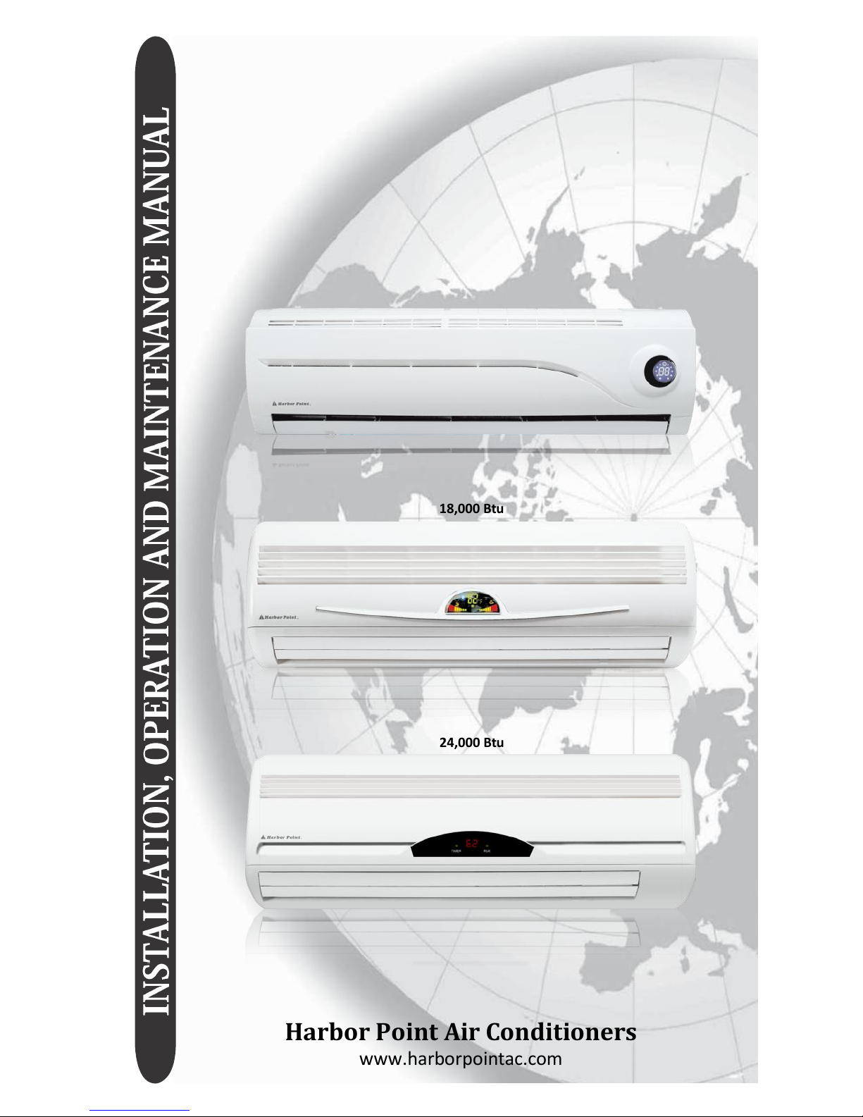
WALL SPLIT DUCTLESS
COOLING
ONLY AND HEAT PUMP SYSTEMS
Harbor Point Air Conditioners
www.harborpointac.com
Cooling Only Models
HF-25GW/GX1B
HF-35GW/GX1B
HF-51GW/GX1A
HF-70GW/GX1A
Heat Pump Models:
HFR-25GW/GX1B
HFR-35GW/GX1B
HFR-51GW/GX1A
HFR-70GW/GX1A
9,000 Btu / 12,000 Btu
18,000 Btu
24,000 Btu
HARBOR POINT WALL SPLIT DUCTLESS SYSTEMS
INSTALLATION, OPERATION AND MAINTENANCE MANUAL
This manual is intended as an aid to a qualified service personnel for proper
installation, operation, and maintenance of Harbor Point Air high efficiency R-410A
Wall Split Ductless Systems. Carefully read these instructions before attempting
installation or operation. Failure to follow these instructions may result in improper
installation, operation, or maintenance, possibly resulting in fire, electrical shock,
property damage, personal injury, or death.
Shipping Damage MUST be Reported to the Carrier IMMEDIATELY!!!
Examine the carton for signs of damage if any is evident open packaging and
check the unit for shipping damage.
TO THE INSTALLER
SAFETY INSTRUCTIONS
Read all instructions before using
the Harbor Point high efficiency
system. Install or locate this sys-
tem only in accordance with these
instructions. Use this system only
for its intended use as described in
this manual.
(1) Retain this manual for future reference.
(2) Before leaving the premises, review this
manual to be sure the unit has been
installed correctly and run the unit for
one complete cycle to make sure it
functions properly.
To obtain technical service or warranty
assistance during or after the installation
of this unit, check our website at
www.harborpointac.com or call your
installing contractor or distributor. Our
technical service department may be
contacted at 1-888-908-9888.
When calling for assistance, please have
the following information ready:
Check rating plate for correct system
voltage before installing. Installation and operation of a system with
the incorrect voltage may result in
malfunction or other issues and will
void the warranty.
The Harbor Point system must be
connected only to a properly
grounded electrical supply. Do not
fail to properly ground this unit.
• Indoor Unit
Model Number
Turn off the electrical supply before
servicing the Harbor Point system.
• Indoor Unit
Serial Number
Do not use the Harbor Point
system if it has damaged wiring, is
not working properly, or has been
damaged or dropped.
• Outdoor Unit
Model Number
• Outdoor Unit
Serial Number
[Save These Instructions]
• Date of installation
This symbol is an indication of
Important Safety Information.
!
!
2

HARBOR POINT WALL SPLIT DUCTLESS SYSTEMS
! !
DANGER
INSTALLER SUPPLIED ITEMS
Tampering with the Harbor Point
system is dangerous and may
result in serious injury or death.
Tampering voids all warranties. Do
not attempt to modify or change
these units in any way.
• Main System Breaker: Sized per unit
requirements, to be mounted adjacent
to outdoor unit.
• Mounting Hardware: Wall anchors,
condenser pad.
• Vacuum Pump
• Gauge Set : R-410 specific.
• High Voltage Interconnect Wiring:
14 AWG wiring from outdoor unit to indoor unit for power and control. *
• Refrigerant : R-410A required for addi-
tional line sets beyond 16 ft.
* Can be purchased through the factory as an
accessory, (part of the Tube Set Kit below)
PRODUCT DESCRIPTION
The Harbor Point system is an efficient
wall split ductless conditioning system
with cooling capacities from 9,000-24,000
Btu and heat pump capacity of 9,000-
24,000 Btu. Designed for quiet operation
and boasting compact dimensions, the
Harbor Point system includes advanced
features like auto-restart, full feature
remote control.
Comprised of three standard components
the indoor evaporator, the outdoor
condensing unit, and an infrared handheld
remote control are engineered to the
highest performance and reliability. The
evaporator is equipped with permanent
washable air filters as well as motorized
air sweep for enhanced air circulation,
and the condensing unit is equipped as
standard with a high efficiency rotary
compressor.
Harbor point recommends the system for
residential and light commercial cooling
and heating applications and will operate
in standard cooling mode down to 60°F
outdoor temperature.
ACCESSORY
Tube-Set Kit consisting of:
• Refrigerant Line Set - 16.4 feet of
suction and liquid line, both fully in-
sulated, and flare fittings supplied
on both ends.
• Interconnecting High Voltage Wiring
-16.4 feet supplied.
• Additional Condensate Tubing - 6 feet
extra supplied.
FACTORY SUPPLIED ITEM
• Matched System Consisting Of:
Evaporator section and condenser section with remote control.
ITEMS FOR CONSIDERATION
Application:
Check the application of the unit prior to
installation, certain applications require
additional components or installation pa-
rameters, such as the need for external
condensate pump or if the system will
need to perform low ambient cooling at
outdoor temperatures below 60°F.
3
HARBOR POINT WALL SPLIT DUCTLESS SYSTEMS
CHOOSING UNIT MODEL
4
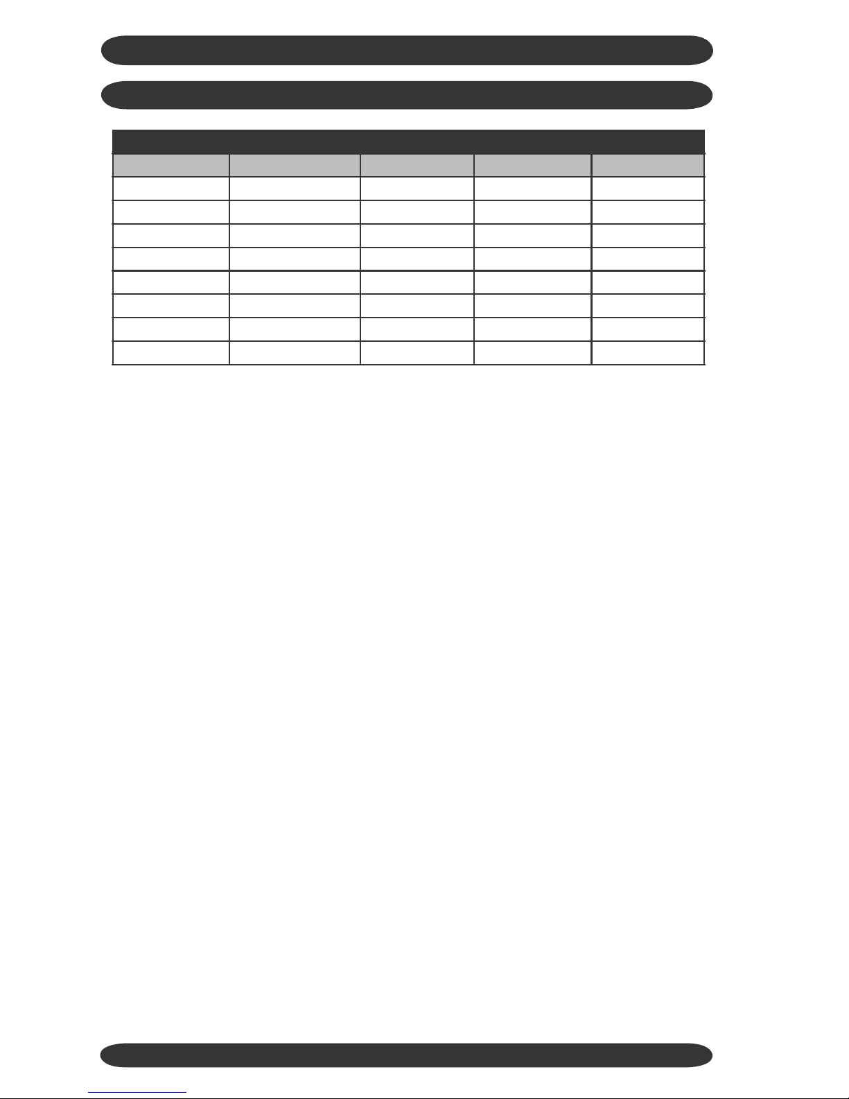
MODELS OFFERED
Indoor Model #
Outdoor Model #
Duty
Capacity Btuh
Voltage
HF-25G/GX1b
HF-25G/GX1b
Cooling Only
9,000
115-1-60
HF-35G/GX1b
HF-35G/GX1b
Cooling Only
12,000
115-1-60
HF-51G/GX1a
HF-51G/GX1a
Cooling Only
18,000
208/230-1-60
HF-70G/GX1a
HF-70G/GX1a
Cooling Only
24,000
208/230-1-60
HFR-25G/GX1b
HFR-25G/GX1b
Heat Pump
9,000
115-1-60
HFR-35G/GX1b
HFR-35G/GX1b
Heat Pump
12,000
115-1-60
HFR-51G/GX1a
HFR-51G/GX1a
Heat Pump
18,000
208/230-1-60
HFR-70G/GX1a
HFR-70G/GX1a
Heat Pump
24,000
208/230-1-60
HARBOR POINT WALL SPLIT DUCTLESS SYSTEMS
PRE INSTALLATION
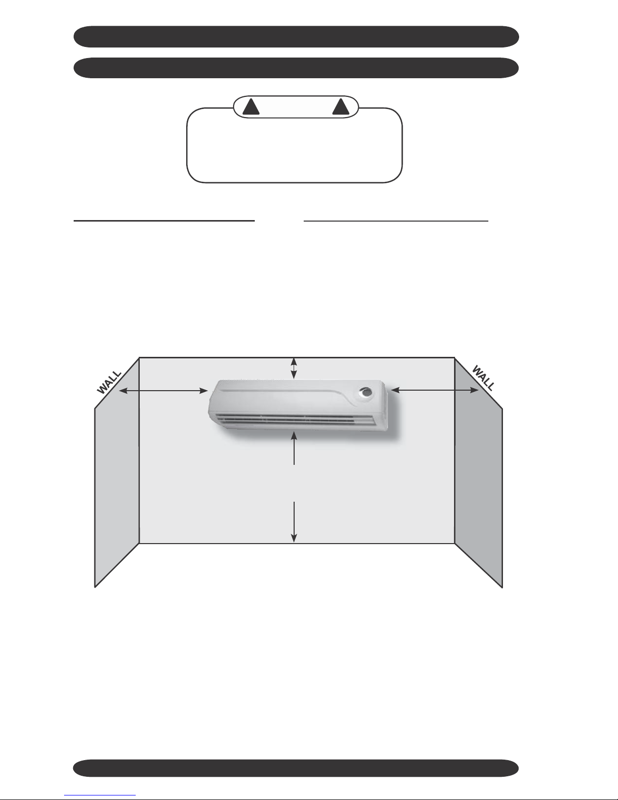
Determine the best location for mounting
the indoor unit, it must be located a mini-
mum of 4 ft (6 ft or more recomended) from
the floor and no less than 6” from ceiling.
CONTROLS AND COMPONENTS
Units are supplied with a wireless remote
control, which communicates with the unit
microprocessor control. The return air
temperature sensor mounted in the in-
door unit provides input to the control for
system operation.
Pay attention to the air circulation in the
room, 9,000 & 12,000 Btuh units throw air
15ft, 18,000 & 24,000 Btuh units throw air
25ft, ensure no obstacles to airflow exist.
Several modes of operation are available
to the end user depending on the type of
comfort required. All unit operating func-
tions are controlled via the remote con-
trol. Refer to “System Operation” section
of this manual.
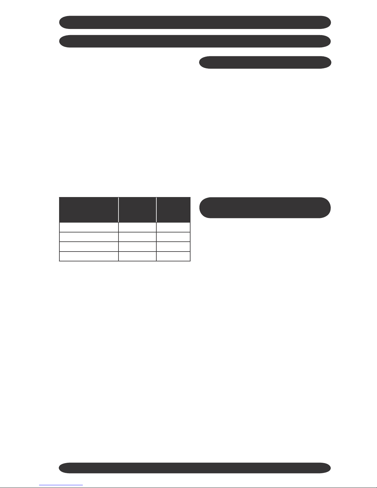
Locate the indoor and outdoor units as close
together as possible, maximum line set run
and lift MUST NOT BE EXCEEDED. Deter-
mine how the interconnect piping, wiring
and condensate hose are to be run.
OPTIONAL CONTROLS AND
COMPONENTS
Lift
Low Ambient Control:
Please consult the factory for availability of
approved method of low ambient cooling
operation.
Condensate Pump:
It is recommended to use the supplied
condensate drain hose in a gravity fed
method whenever possible. If this can
not be done then a field installed pump
that is external to the evaporator would
be required.
Ensure that all panels can be removed for
service as required.
Certification:
All Harbor Point Systems are certified by
UL under UL Standard 1995. Per-
formance is varified by CSA under ARI
210/240 test standard.
5
Unit
Max Line
Set Run
Max
Vertical
HF-25/HF-35
50 Feet
17 Feet
HF-51/HF-70
50 Feet
17 Feet
HFR-25/HFR-35
50 Feet
17 Feet
HFR-51/HFR-70
50 Feet
17 Feet
HARBOR POINT WALL SPLIT DUCTLESS SYSTEMS
INDOOR UNIT INSTALLATION
!
!
CAUTION
Follow Instructions, failure to follow
instructions may cause possible malfunction and void any warranty.
Remove indoor and outdoor units from
the carton/box. Indoor unit carton con-
tains, remote control and batteries, en-
sure these are kept in a safe place during
installation.
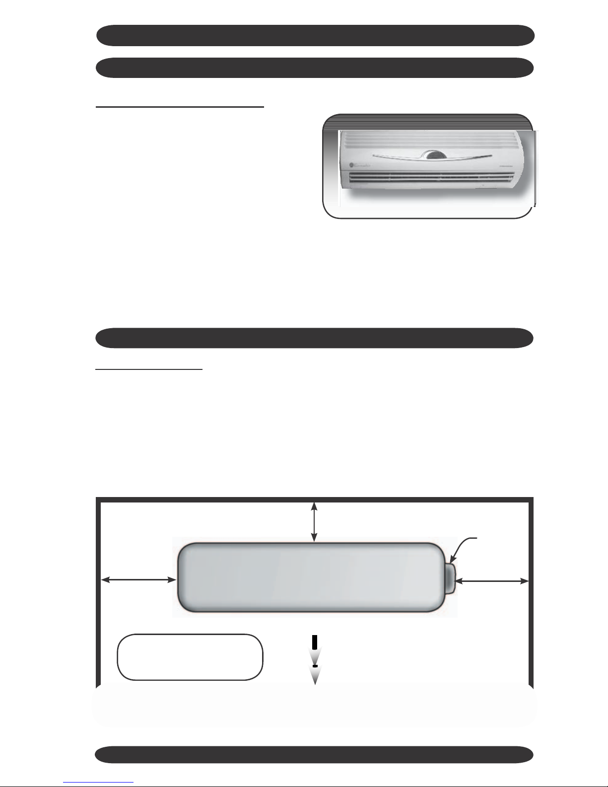
Locate area to install indoor unit the
unit should be located a minimum of 6 ft.
from the floor and 6” from the ceiling.
Choose an area where the wall is plumb
and determine how to best to run the unit
interconnects.
CEILING
6” from ceiling minimum
from wall
FLOOR
Ensure no obstacles to airflow are directly
in front of the unit, for a minimum of 12 ft
for 9,000/12,000 Btuh units and 16 ft for
18,000/24,000 Btuh units.
Do not install the Indoor unit units in areas
exposed to high humidity (Relative Hu-
midity of 80% or more), direct sunlight and
direct heat from stoves or other devices.
6
6” from ceiling m
4ft from floor (minimum)
6ft plus from floor (optimum)
8”
from wall
minimum
8”
minimum
HARBOR POINT WALL SPLIT DUCTLESS SYSTEMS
INDOOR UNIT INSTALLATION
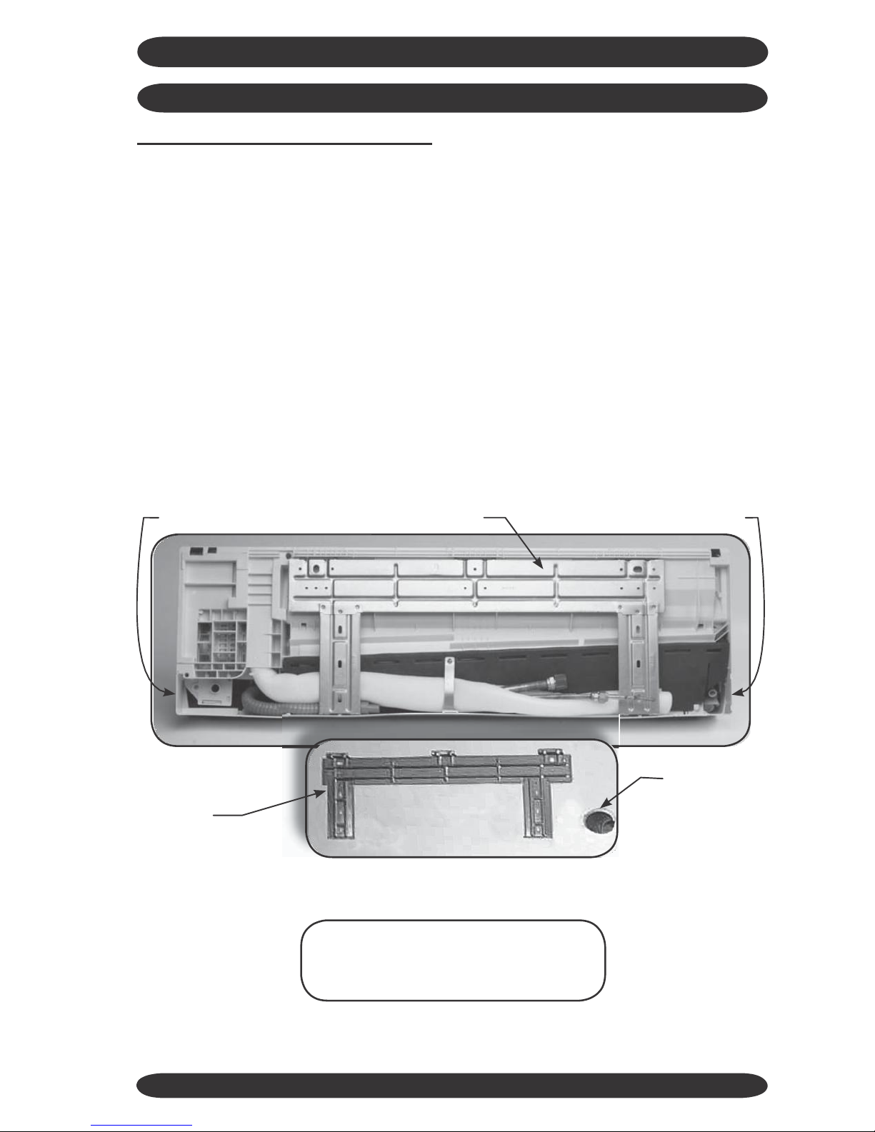
Prepare the evaporator for mounting
by removing the mounting bracket from
the rear of the indoor unit. Use a Phillips
head screwdriver to remove the unit pipe
strap. If the unit is a heat pump the de-
frost sensor also must be undone from its
retainer.
If mounting the unit on an inside wall, use
the knockouts provided on the left and
right sides of the unit to route the piping
and wiring connections through.
The indoor unit weighs a maximum of
20 Lbs. Use wall anchors to secure the
mounting bracket to a wall stud and en-
sure that the wall is capable of holding the
weight of the unit.
If mounting the unit on an outside wall
measure from the edges of the unit to the
center of the line set 90° bend to locate the
the center of the wall penetration. Drill a
3” ø hole through the wall. Angle the wall
penetration slightly down towards the out-
side to assist in draining the condensate
away from the unit.
Be sure mounting bracket is level, so that
the condensate can drain properly.
knockout
knockout
remove mounting bracket
mounting
bracket
on wall
3” ø hole
Note: Prepare all wiring and piping
connections before hanging the unit
on the mounting bracket.
7
HARBOR POINT WALL SPLIT DUCTLESS SYSTEMS
INDOOR UNIT INSTALLATION
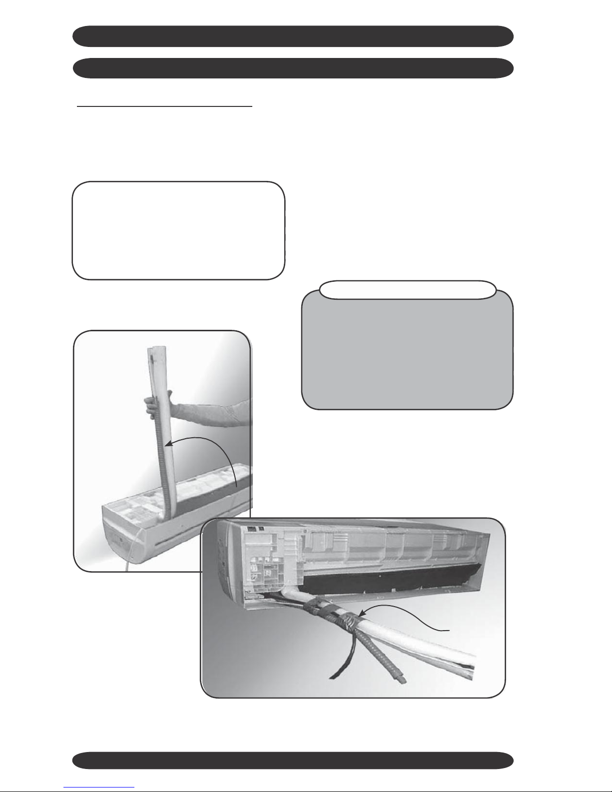
Prepare unit line set connections
Rotate refrigerant line stubs gently to 90°
(if mounting on an outside wall). For oth-
er line set configurations align the stubs
as required.
Feed the 14 AWG interconnect wiring
between indoor and outdoor through
the unit electrical connection (maxi-
mum number of 6 wires is required) (if
required by local codes an electrical
connector can be attached to the rear
of the unit). Tape the loose wire to the
line set stubs. (See Electrical Wiring In-
stall section.) These two tips save time
and prevent damage to the stubs when
mounting the indoor unit.
Tip: Use Duct tape to tape the Con-
densate hose (make sure it is below
the Line set stubs) and the defrost
sensor (heat pump only). This makes
it easier to guide them through the
hole in the wall.
HEAT PUMP SYSTEMS
Very Important! Make sure the de-
frost sensor wire is run and connected
between the indoor and outdoor units,
or the heat pump system will not oper-
ate in heat mode. Refer to “Heat Pump
Wiring” section of this manual.
duct tape
8
HARBOR POINT WALL SPLIT DUCTLESS SYSTEMS
INDOOR UNIT INSTALLATION
Install unit on mounting bracket
Feed the line set stubs/condensate hose/
wiring connections through a ø 3” hole in
the wall.
Position the evaporator so that the “key”
slots on the back of the unit slide onto the
tabs on top of the mounting bracket. Then
push the lower portion of the evaporator
against the bracket until it latches into the
mounting bracket.
18,000
Btuh
shown
through the wall penetration, also check
that the wall is plumb. The unit must be
level and plumb for proper condensate
removal.
Indoor unit is now installed, it should be
plumb, level and flush with the wall. Insure that the line set stubs are completely
OUTDOOR UNIT INSTALLATION
Locate Outdoor unit
Select a location with proper ventilation,
minimizing recirculation possibility. Do not
install the outdoor unit in a location ex-
posed to high winds (field fabricated and
installed wind baffle may be required).
Ensure location does not impede access
around unit and pose a disturbance to
neighboring areas.
Install the outdoor unit on a condenser
service pad. If unit is a heat pump ex-
tend feet to raise 6” to allow for defrost
to drain away.
Clearances for the Outdoor unit:
Front
Condenser Fan
9
12” Minimum
Service
Rear
Valves
Outdoor Unit
12” Minimum
12” Minimum
Airflow
Note: Consult factory if
48” Minimum
minimum clearances can’t
be maintained.
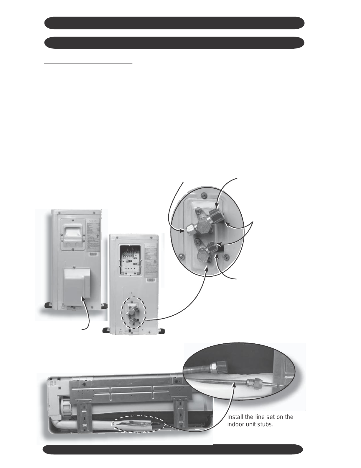
Install the line set on the
indoor unit stubs.
HARBOR POINT WALL SPLIT DUCTLESS SYSTEMS
Service port
Gas line service valve
Line set connections
under the GRAY
caps.
Outdoor
Unit
Liquid line service valve
9,000/12,000 shown
18,000/24,000 has additional
liquid line port
remove line
set cover
Indoor Unit
10
Refrigerant Line Set Piping
Interconnecting line set between th e
outdoor unit and the indoor unit, must have
both refrigerant lines insulated as the
expansion device is located in the outdoor
unit.
Gently bend the line set stubs from the
in- door unit to the desired location.
Using 2 x 10”/12” Crescent wrenches
remove the flare nuts from the indoor
unit line stubs.
The indoor unit is filled with a dry
gas, check for release of this to ensure
that no leaks are present. Use a small
amount of vacuum pump oil on the male
flare threads to ease installation.
Connect the line set to the stubs.
Using the 2 wrenches, 1 on the male
and 1 on the female tighten the flare
nuts. Run the line set to the outdoor
unit, avoid tight bends and kinking
the lines.
If line set length is in excess of that
re- quired, cut line set and re-flare or
coil ex- cess vertically to facilitate oil
return to the compressor.
HARBOR POINT WALL SPLIT DUCTLESS SYSTEMS
OUTDOOR UNIT INSTALLATION
Evacuation
Gauges can now be attached to the service
ports - SERVICE PORTS HAVE A 5/16”
CONNECTION TO GAUGES, which is dif-
ferent from the norm for R-22. You will need
specific hoses or an adaptor for the 5/16”
connection.
Once the gauges are attached the line
set can be leak checked using Nitrogen
at 300 psig. Evacuate the unit and inter-
connect down to a minimum of 400-500
Microns, break vacuum with Nitrogen to
further leak check.
Re-evacuate the system down to 300-400
Microns or lower for a period of one hour.
This is an R-410A System it is essential
that a deep vacuum be pulled on the sys-
tem to remove all traces of moisture. See
“System Start-Up” section to fine-tune the
refrigerant charge.
Main Power Wiring
Electrical wiring should be done in accordance with all National Electrical Code
(NEC) and local state/city building codes.
Note: A small screwdriver is required
for unit terminals.
Breaker size and wiring must be sized
for the rating plate amperage, MCA and
HACR. Use only HACR type breakers,
each system installed must have a sep-
arate branch
breaker/fuse.
circuit with an individual
Max
tion. Ground connection must be made to
the terminal plate.
Heat Pump (208/230 V) unit terminals:
L1 - L2 : Power from breaker + G
L3 - L4 : Power to indoor unit + G
1 - 2 - 3 : Control signals
These are just examples of typical wiring
connections. Always refer to Wire Diagram
on unit for actual wiring connections.
A local disconnect should be installed ad-
jacent to the outdoor unit in accordance
with National and Local Codes. The out-
door unit provides power for the indoor
unit, no disconnect is required between
the outdoor and indoor units.
Line voltage from the disconnect should
be wired to:
N - L (115V Unit), + G
L1 - L2 (208/230V Unit), + G
Remove right side knockout on the termi-
nal access panel for whip/wiring connec-
Tip: For easier access to the terminals in the
outdoor unit remove the lower access panel to
install whip and sealtite connectors for conduit.
11
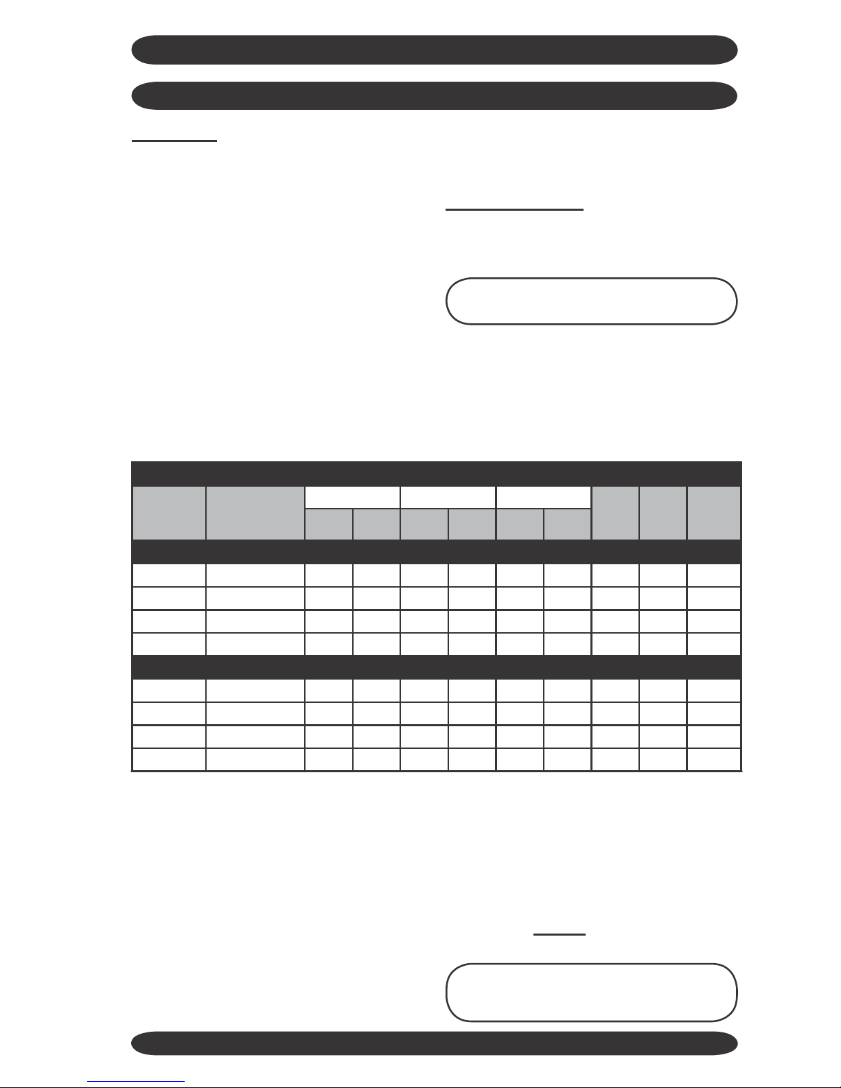
Electrical Specifications
Nominal
Capacity
Btuh
Volts/Hz/Ph
Compressor
Cond Fan
Indoor Fan
Total
FLA
MCA
HACR
Fuse
RLA
LRA
Watts
RLA
Watts
RLA
Cooling Models Only
9,000
115/60/1
7.5
47
35
0.81
16
0.35
7.2
10.6
15.0
12,000
115/60/1
9.9
53
45
0.80
16
0.35
9.6
14.0
20.0
18,000
208/230/60/1
6.6
42
60
0.85
40
0.40
6.4
9.5
15.0
24,000
208/230/60/1
10.0
46
60
0.90
40
0.40
8.1
13.8
23.8
Heat Pump Models Only
9,000
115/60/1
7.5
47
35
0.81
16
0.35
7.2
10.6
15.0
12,000
115/60/1
9.9
53
45
0.80
16
0.35
9.6
14.0
20.0
18,000
220/60/1
6.6
42
60
0.85
40
0.40
6.4
9.5
15.0
24,000
208/230/60/1
10.0
46
60
0.90
40
0.40
8.1
13.8
23.8
 Loading...