

Page 1

1/2ʺ Drive Digital Torque Adapter
68283 1/2” Drive Digital Torque Adapter
Read this material before using this product.
Failure to do so can result in serious injury.
SAVE THIS MANUAL.
When unpacking, make sure that the product is intact and undamaged. If any parts
are missing or broken, please call 1-800-444-3353 as soon as possible.
Visit our website at: http://www.harborfreight.com
Copyright© 2010 by Harbor Freight Tools®. All rights reserved. No portion of this manual or any artwork contained herein may be reproduced in any shape
or form without the express written consent of Harbor Freight Tools. Diagrams within this manual may not be drawn proportionally. Due to continuing
improvements, actual product may differ slightly from the product described herein. Tools required for assembly and service may not be included.
Page 2
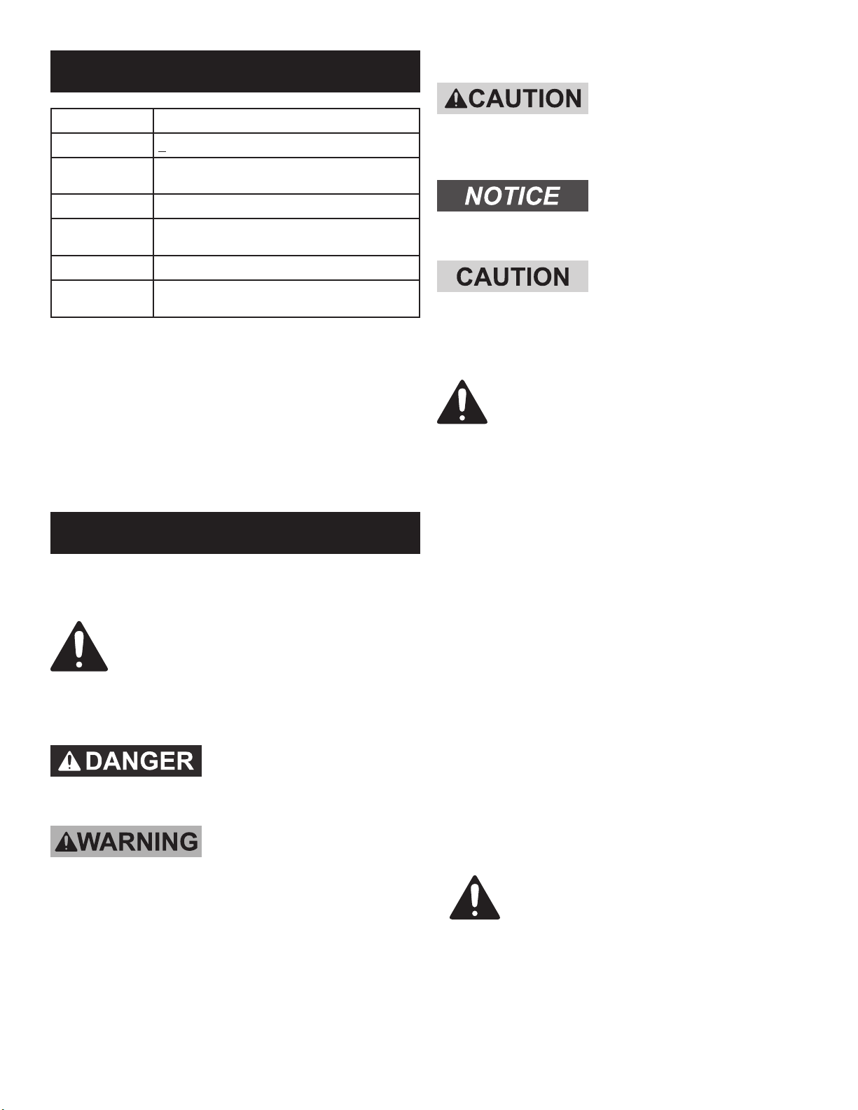
Specications
Drive Size 1/2”
Accuracy + 2%
Included
Adapters
Torque Range 29.5 ft-lb. to 147.5 ft-lb.
Auto
Shutdown
Memory Stores up to 50 torque readings
Battery
1/2” - 3/8”
1/2” - 1/4”
After 80 Seconds
One 3-volt CR2032 button cell battery
(Included)
Save This Manual
Keep this manual for the safety warnings and precautions,
assembly, operating, inspection, maintenance and
cleaning procedures. Write the product’s serial
number in the back of the manual near the assembly
diagram (or month and year of purchase if product
has no number). Keep this manual and the receipt
in a safe and dry place for future reference.
CAUTION, used with the safety alert symbol,
indicates a hazardous situation which, if not
avoided, could result in minor or moderate injury.
NOTICE is used to address practices
not related to personal injury.
CAUTION, without the safety alert symbol, is used
to address practices not related to personal injury.
General Safety Warnings
WARNING Read all safety warnings and
instructions. Failure to follow the warnings and
instructions may result in serious injury.
Save all warnings and instructions
for future reference.
1. Do not exceed the Digital Torque
Adapter’s max. torque value.
Important Safety Information
In this manual, on the labeling, and all other
information provided with this product:
This is the safety alert symbol. It is used
to alert you to potential personal injury
hazards. Obey all safety messages that
follow this symbol to avoid possible injury
or death.
DANGER indicates a hazardous situation which, if
not avoided, will result in death or serious injury.
WARNING indicates a hazardous situation which, if
not avoided, could result in death or serious injury.
2. Position battery in proper polarity and do
not install battery of different type.
3. Do not submerge Digital Torque Adapter.
4. Do not disassemble Digital Torque Adapter.
5. Do not expose the Digital Torque Adapter to
extreme temperature, humidity, or direct sunlight.
6. Do not excessively shake Digital Torque Adapter.
7. This product is not a toy. Keep it
out of reach of children.
8. The warnings, precautions, and instructions discussed
in this instruction manual cannot cover all possible
conditions and situations that may occur. It must
be understood by the operator that common sense
and caution are factors which cannot be built into
this product, but must be supplied by the operator.
SAVE THESE
INSTRUCTIONS.
Page 2For technical questions, please call 1-800-444-3353.SKU 68283
Page 3

Instructions for Putting into Use
Read the ENTIRE IMPORTANT SAFETY
INFORMATION section at the beginning
of this manual including all text
under subheadings therein before
set up or use of this product.
Note: For additional information regarding the
parts listed in the following pages, refer to Parts List
and Assembly Diagram on page 4.
1. Securely fasten Adapter to ratchet.
2. Attach an adapter to end of anvil, if desired.
Once fastened, press the Power button
to activate the Adapter. The LCD Display
will show “trACE” and “PtoP.”
3. After two seconds, the Display will show “00.0”.
4. Swing the Adapter. The Display will
show the measured torque.
5. Note: If you do not use the Adapter for 80
seconds, the Adapter will automatically shut off.
Functions
Decrease
Torque
Memory
Operating Instructions
Read the ENTIRE IMPORTANT SAFETY
INFORMATION section at the beginning
of this manual including all text under
subheadings therein before set up or use of
this product
Display
LED
Light
PowerPeak and Trace
Anvil
Increase
Torque
6. Press the Memory (“M”) button and the “P/T” button
at the same time to select the desired torque unit.
7. The Adapter contains three unit
selections: kg-m, ft-lb and N-m.
8. To increase the current torque value, press and hold
down the Increase (“+”) button until value is reached.
9. To lower the current torque value, press and hold
down the Decrease (“-”) button until value is reached.
10. Note: The Display will show “00.0” if no
selection is made after ten seconds.
11. During operation, the LED light will ash GREEN.
12. Once you are 20% away from targeted torque, the
LED will ash YELLOW and the buzzer will beep.
13. When targeted torque is reached, the LED will
change to RED and a long buzz will sound.
14. To set peak torque, press and release the
“P/T” button when Adaptor is on.
15. The Display will show “PtoP” and
then “00.0” two seconds later.
16. To trace torque setting, press and
release the “P/T” button.
17. The Display will show “trACE” and
then “00.0” two seconds later.
18. To store a torque reading, have the digital torque
wrench in “PtoP” mode. When you use it, the torque
wrench can store the reading automatically.
19. Press the Memory button. The Display Panel
will show the stored reading as “P01”.
20. To show the second stored reading, press the
Memory button again for one second. The second
torque value will be designated as “P02”.
21. You can continue to store settings until you
reach fty saved settings, or “P50”.
Page 3For technical questions, please call 1-800-444-3353.SKU 68283
Page 4

22. Note: “P50” will be the most recent saved
setting while “P01” will be the oldest.
depend on battery quality and amount of hours
tool is used. Typical battery life is 110 hours.
23. If the torque setting is exceeded by 125% of the full
scale, the LED will ash RED and the alarm will beep.
24. WARNING! Do not press the Memory and
Power buttons at the same time. This will
calibrate the tool and alter the preset values.
25. To turn off the Adapter, press the Power button OR wait
80 seconds for the Adapter to turn off automatically.
26. Clean, then store the tool indoors
out of children’s reach.
Maintenance and Servicing
Procedures not specically explained
in this manual must be performed
only by a qualied technician.
Replacing Batteries
1. NOTE: When battery power is low, a “ ” icon
will appear on the display screen. Battery life will
Parts List
2. To replace battery, remove Battery Cap.
3. Remove old battery.
4. Install new CR2032 button cell battery, making sure to
follow indicated polarity (the “+” should face upwards).
5. Replace Battery Cap.
6. Remove the battery if Torque Adapter
will be stored for a long time.
Cleaning, Maintenance,
and Lubrication
1. BEFORE EACH USE, inspect the general condition
of the tool. Check for loose hardware, misalignment
or binding of moving parts, cracked or broken
parts, damaged electrical wiring, and any other
condition that may affect its safe operation.
2. AFTER USE, wipe external surfaces
of the tool with clean cloth.
3. Do not use cleaning agents to clean the plastic parts
of the tool. Use only a mild detergent or a damp
cloth. Do not let water come into contact with tool.
PLEASE READ THE FOLLOWING CAREFULLY
THE MANUFACTURER AND/OR DISTRIBUTOR HAS PROVIDED THE PARTS LIST AND ASSEMBLY DIAGRAM IN
THIS MANUAL AS A REFERENCE TOOL ONLY. NEITHER THE MANUFACTURER OR DISTRIBUTOR MAKES ANY
REPRESENTATION OR WARRANTY OF ANY KIND TO THE BUYER THAT HE OR SHE IS QUALIFIED TO MAKE ANY REPAIRS
TO THE PRODUCT, OR THAT HE OR SHE IS QUALIFIED TO REPLACE ANY PARTS OF THE PRODUCT. IN FACT, THE
MANUFACTURER AND/OR DISTRIBUTOR EXPRESSLY STATES THAT ALL REPAIRS AND PARTS REPLACEMENTS SHOULD
BE UNDERTAKEN BY CERTIFIED AND LICENSED TECHNICIANS, AND NOT BY THE BUYER. THE BUYER ASSUMES
ALL RISK AND LIABILITY ARISING OUT OF HIS OR HER REPAIRS TO THE ORIGINAL PRODUCT OR REPLACEMENT
PARTS THERETO, OR ARISING OUT OF HIS OR HER INSTALLATION OF REPLACEMENT PARTS THERETO.
Parts List
Part Description Qty.
1 Upper Housing 1
2 Control Panel 1
3 Display Panel 1
4 LED 1
5 Circuit Board 1
6 Adapter 1
7 Ratchet Gauge 1
Record Product’s Serial Number Here:
Note: If product has no serial number, record month and year of purchase instead.
Part Description Qty.
8 Buzzer 1
9 Lower Housing 1
10 Screw 10
11 Battery Holder 1
12 Battery 1
13 Battery Cap 1
Note: Some parts are listed and shown for illustration purposes only,
and are not available individually as replacement parts.
Page 4For technical questions, please call 1-800-444-3353.SKU 68283
Page 5

Assembly Diagram
1
2
3
4
5
6
7
8
9
10
11
12
13
10
Page 5For technical questions, please call 1-800-444-3353.SKU 68283
Page 6

3491 Mission Oaks Blvd. • PO Box 6009 • Camarillo, CA 93011 • (800) 444-3353
Page 6For technical questions, please call 1-800-444-3353.SKU 68283
 Loading...