

Page 1
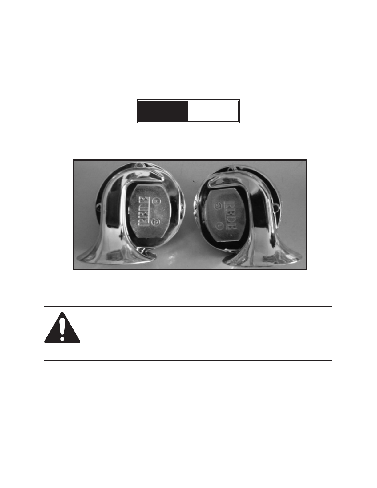
2 PIECE 12 VOLT DC
ELECTRIC HORN SET
Model
99911
INSTALLATION AND OPERATING INSTRUCTIONS
Visit our website at: http://www.harborfreight.com
Read this material before using this product.
Failure to do so can result in serious injury.
SAVE THIS MANUAL.
Copyright© 2008 by Harbor Freight Tools®. All rights reserved. No portion of this manual or any artwork
contained herein may be reproduced in any shape or form without the express written consent of Harbor
Freight Tools. Diagrams within this manual may not be drawn proportionally. Due to continuing improve-
ments, actual product may differ slightly from the product described herein. Tools required for assembly
and service may not be included.
For technical questions or replacement parts, please call 1-800-444-3353.
Revised Manual 10e
Page 2
SPECIFICATIONS
Operating Power 12 VDC
Sound Level 110 Db +
UNPACKING
When unpacking, make sure that the
item is intact and undamaged. If any parts are
missing or broken, please call Harbor Freight
Tools at the number shown on the cover of this
document as soon as possible.
IMPORTANT SAFETY
INFORMATION
Install according to these instructions 1.
only. Improper installation can create
hazards.
Wear ANSI-approved safety goggles 2.
and heavy-duty work gloves during
Installation.
Keep assembly area clean and well lit.3.
Do not install when tired or when under 4.
the inuence of drugs or medication.
This product is not a toy. Do not allow 5.
children to play with or near this item.
Use for intended purpose(s) only.6.
Inspect before each use; do not use if 7.
parts loose or damaged.
Do not install while engine is running.8.
Attach the Electric Relay (2) to the inside 3.
of the engine bay using the Relay Mounting Bolt/Nut (4).
NOTE:4. Verify that installation surface has
no hidden utility lines before drilling or
driving screws.
Wire the two Horns (1A/1B), the Electric 5.
Relay (2), 12 VDC horn switch (not
supplied), and 10 amp in-line fuse (not
supplied) using 14 or 16 gauge electric
wire. Use the Parts List and Assembly
Diagram as well as the Wiring Diagram
on page 3 as a guide.
NOTE:6. If you are using your existing
horn switch you may need the assistance
of an electrical mechanic to install these
horns. The wiring diagram provided is
intended for very basic installation.
NOTE:7. The in-line 10 amp fuse may not
be required if you are connecting your
Electric Relay (2) through a 10 A fuse in
your existing fuse box.
Before operating the vehicle, make sure 8.
all your electrical connections and new
installation is secure and wired correctly.
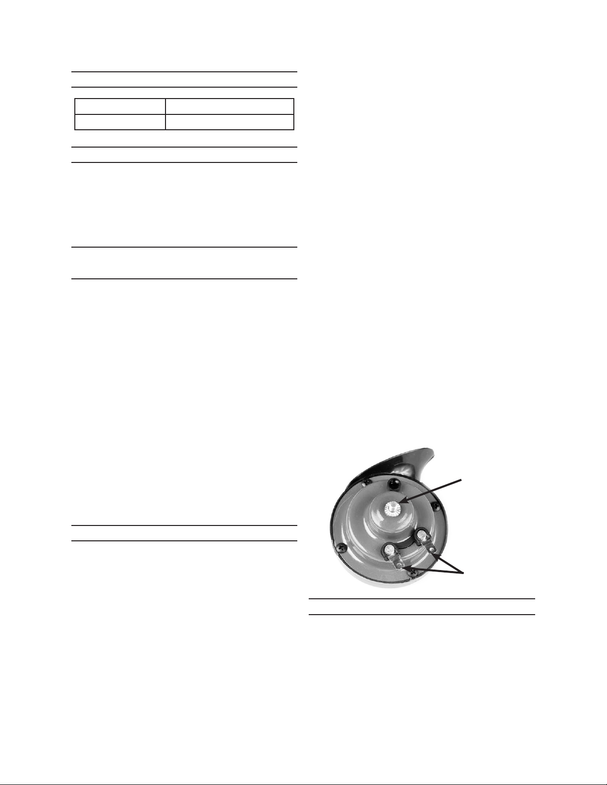
(Photo may differ slightly
from acual product)
Mounting
Bracket (3)
connects here.
INSTALLATION
There is a bolt located in the center 1.
of each horn with a nut attached to it.
Remove the nut, then place the bolts
through one the holes in the Mounting
Bracket (3). Thread the nut back onto the
bolt to secure the Mounting Bracket (3)
onto each Horn (1A/1B).
Attach the Mounting Brackets (3) to the 2.
inside of the engine bay using sheet
metal screws (not supplied). See photo
above.
TROUBLE SHOOTING
If the Horns (1) do not sound after installing,
check to make sure there is 12 VDC on the
positive (+) connections of the horns when
you active the horn switch. Do a continuity
test between the negative (-) connection of
the Horns (1) and the negative (-) post of the
battery to verify a good ground.
SKU 99911 For technical questions, please call 1-800-444-3353. Page 2
Electric wires
connect here.
REV 09b
Page 3

PARTS LIST AND ASSEMBLY
DIAGRAM
Part Description Qty.
1A 12 VDC Electric Horn (low tone) 1
1B 12 VDC Electric Horn (high tone) 1
2 Electric Relay 1
3 Mounting Bracket 1
4 Relay Mounting Bolt And Nut 1
1B
3
4
1A
2
PLEASE READ THE
FOLLOWING CAREFULLY
THE MANUFACTURER AND/OR
DISTRIBUTOR HAS PROVIDED THE
PARTS LIST AND ASSEMBLY DIAGRAM IN
THIS MANUAL AS A REFERENCE TOOL
ONLY. NEITHER THE MANUFACTURER
OR DISTRIBUTOR MAKES ANY
REPRESENTATION OR WARRANTY OF
ANY KIND TO THE BUYER THAT HE
OR SHE IS QUALIFIED TO MAKE ANY
REPAIRS TO THE PRODUCT, OR THAT HE
OR SHE IS QUALIFIED TO REPLACE ANY
PARTS OF THE PRODUCT. IN FACT, THE
MANUFACTURER AND/OR DISTRIBUTOR
EXPRESSLY STATES THAT ALL REPAIRS
AND PARTS REPLACEMENTS SHOULD
BE UNDERTAKEN BY CERTIFIED AND
LICENSED TECHNICIANS, AND NOT BY
THE BUYER. THE BUYER ASSUMES ALL
RISK AND LIABILITY ARISING OUT OF
HIS OR HER REPAIRS TO THE ORIGINAL
PRODUCT OR REPLACEMENT PARTS
THERETO, OR ARISING OUT OF HIS OR
HER INSTALLATION OF REPLACEMENT
PARTS THERETO.
WIRING DIAGRAM FOR NEGATIVE GROUND ELECTRICAL SYSTEM
Connect to chassis
or negative (-)
battery terminal
_
Relay (2)
(view from bottom)
Horn (1A)
+
Horn Switch
(not supplied)
85
87
86
30
+
Horn (1B)
~
_
Connect to chassis
or negative (-)
battery terminal
10A Fuse
(not supplied)
Connect to positive
(+) terminal of battery
+
REV 10e
SKU 99911 For technical questions, please call 1-800-444-3353. Page 3
 Loading...