

Page 1
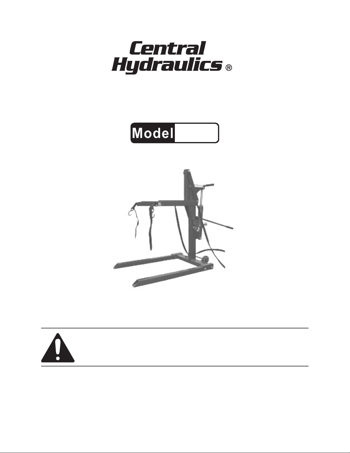
HIGH POSITION
MOTORCYCLE LIFT
99887
SET UP AND OPERATING INSTRUCTIONS
Distributed exclusively by Harbor Freight Tools®.
3491 Mission Oaks Blvd., Camarillo, CA 93011
Visit our website at: http://www.harborfreight.com
Read this material before using this product.
Failure to do so can result in serious injury.
SAVE THIS MANUAL.
Copyright© 2008 by Harbor Freight Tools®. All rights reserved. No portion of this manual or any artwork
contained herein may be reproduced in any shape or form without the express written consent of
Harbor Freight Tools. Diagrams within this manual may not be drawn proportionally. Due to continuing
improvements, actual product may differ slightly from the product described herein. Tools required for
assembly and service may not be included.
For technical questions or replacement parts, please call 1-800-444-3353.
Page 2
SAVE THIS MANUAL
Keep this manual for the safety warnings and precautions, assembly, operating,
inspection, maintenance and cleaning procedures. Write the product’s serial number
in the back of the manual (or month and
year of purchase if product has no number). Keep this manual and the receipt in
a safe and dry place for future reference.
NOTICE is used to
address practices
not related to personal injury.
CAUTION, without
the safety alert
symbol, is used to address
practices not related to
personal injury.
General Safety Warnings
IMPORTANT SAFETY
INFORMATION
In this manual, on the labeling,
and all other information provided with this product:
This is the safety alert
symbol. It is used to alert
you to potential personal
injury hazards. Obey all
safety messages that
follow this symbol to avoid
possible injury or death.
DANGER indicates
a hazardous
situation which, if not
avoided, will result in death or
serious injury.
WARNING
indicates a
hazardous situation which, if
not avoided, could result in
death or serious injury.
CAUTION, used
with the safety
alert symbol, indicates a
hazardous situation which, if
not avoided, could result in
minor or moderate injury.
WARNING Read all safety
warnings and instructions.
Failure to follow the warnings and
instructions may result in serious
injury.
Save all warnings and
instructions for future reference.
Work area safety1.
Keep work area clean and well lit. a.
Cluttered or dark areas invite accidents.
Keep children and bystanders b.
away while operating the Motorcycle Lift. Distractions can cause you
to lose control.
Personal safety2.
Stay alert, watch what you are do-a.
ing and use common sense when
operating the Motorcycle Lift. Do
not use the Lift while you are tired
or under the inuence of drugs,
alcohol or medication. A moment
of inattention while operating the Liftmay result in serious personal injury.
Use personal protective equip-b.
ment. Always wear ANSI-approved
safety goggles and heavy duty
work gloves. Safety equipment
such as non-skid safety shoes will
reduce personal injuries.
SKU 99887 For technical questions, please call 1-800-444-3353. Page 2
Page 3

Do not overreach. Keep proper c.
footing and balance at all times.
This enables better control of the Lift
in unexpected situations.
Dress properly. Do not wear loose d.
clothing or jewelry. Keep your
hair, clothing and gloves away
from moving parts. Loose clothes,
jewelry or long hair can be caught in
moving parts.
use. Many accidents are caused by
poorly maintained equipment.
Use the Motorcycle Lift and its e.
accessories in accordance with
these instructions, taking into account the working conditions and
the work to be performed. Use of
the Lift for operations different from
those intended could result in a hazardous situation.
Only use safety equipment that e.
has been approved by an appropriate standards agency. Unapproved
safety equipment may not provide
adequate protection. Eye protection
must be ANSI-approved for specic
hazards in the work area.
Tool use and care3.
Do not force the Motorcycle Lift. a.
Use the correct equipment for your
application. The correct equipment
will do the job better and safer at the
rate for which it was designed.
Release any load from the Motor-b.
cycle Lift before making any adjustments, changing accessories,
or storing the unit. Such preventive
safety measures reduce the risk of
accidents.
Store idle equipment out of the c.
reach of children and do not allow
persons unfamiliar with the Motorcycle Lift or these instructions to
operate the unit. Hydraulic tools are
dangerous in the hands of untrained
users.
Maintain the Motorcycle Lift. d.
Check for misalignment or binding
of moving parts, breakage of parts
and any other condition that may
affect the unit’s operation. If damaged, have the Lift repaired before
Service4.
Have your Motorcycle Lift serviced a.
by a qualied repair person using
only identical replacement parts.
This will ensure that the safety of the
Lift is maintained.
Specic Safety Warnings
Maintain labels and nameplates on 1.
the Motorcycle Lift. These carry
important safety information. If unreadable or missing, contact Harbor
Freight Tools for a replacement.
Do not exceed the 2. 1100 pound max-
imum lift capacity of the Motorcycle
Lift. Doing so may cause damage
to the unit and/or serious personal
injury. Beware of dynamic loading.
Dropping or bouncing a load may
briey create an excess load, causing
product failure.
Bleed the hydraulic system of the 3.
Motorcycle Lift before its initial use.
(See pages 6 thru 7.)
Always place the Motorcycle Lift on a 4.
dry, oil/grease free, solid, level oor
surface capable of supporting the
weight of the Lift, its load, and any
additional tools and accessories.
SKU 99887 For technical questions, please call 1-800-444-3353. Page 3
Page 4
Lift the load only by the vehicle 5.
manufacturer’s recommended lifting
points.
Do not leave the Motorcycle Lift unat-17.
tended when it is under a load. Lower the Lift all the way before leaving.
Stay out from under the load while it 6.
is being lifted or supported.
Keep ngers, hands, and feet away 7.
from the Arm Lift assembly when raising or lowering the Lift.
Never use the Motorcycle Lift if the 8.
Position Pin is not engaged (locking
the Arm Lift assembly in place).
Do not use the Motorcycle Lift with 9.
the vehicle’s engine running. When
running, the vehicle’s engine produces carbon monoxide, a colorless, odorless, toxic fume that, when
inhaled, can cause serious personal
injury or death.
Always center the load directly over 10.
the two Arm Lifts.
Always use the two Straps with 11.
Hooks to secure the motorcycle/ATV
to the Lift before raising the load.
Do not use the Motorcycle Lift for 12.
aircraft purposes.
Do not allow anyone on the vehicle 13.
when using the Motorcycle Lift. Keep
all bystanders a safe distance away
from the vehicle.
This Motorcycle Lift is designed for 14.
short term use only. Do not leave a
load on the Lift for extended periods.
Before lowering the Motorcycle Lift, 15.
make sure tool trays and all other
tools and equipment are removed
from under the Lift.
Avoid rapid load descent. Turn the 16.
Release Valve slowly.
This product is not a toy. Keep it out 18.
of reach of children.
The warnings, precautions, and in-19.
structions discussed in this instruction
manual cannot cover all possible conditions and situations that may occur.
It must be understood by the operator
that common sense and caution are
factors which cannot be built into this
product, but must be supplied by the
operator.
SPECIFICATIONS
Maximum Lift Capacity 1100 Pounds
Maximum Lifting Height 30”
Minimum Lifting Height 2-1/2”
Ram Travel 7-3/8”
Distance Between Base Legs 20-3/8”
UNPACKING
When unpacking, check to make sure
that the item is intact and undamaged. If
any parts are missing or broken, please
call Harbor Freight Tools at the number
shown on the cover of this manual as soon
as possible.
ASSEMBLY INSTRUCTIONS
Read the ENTIRE IMPORTANT
SAFETY INFORMATION
section at the beginning of this
manual including all text under
subheadings therein before set
up or use of this product.
SKU 99887 For technical questions, please call 1-800-444-3353. Page 4
Page 5

TO PREVENT
SERIOUS INJURY
FROM ACCIDENTAL
OPERATION:
Release any load from the
Motorcycle Lift before
assembling or making any
adjustments to the unit.
Note: For additional information regarding
the parts listed in the following pages,
refer to the Assembly Diagram near
the end of this manual.
Attach the two Base Legs (12) to the 1.
Post (19) using four Bolts (11) and
four Spring Washers (10).
(See Figure A.)
POST
(19)
BASE LEG
(12)
POST
(19)
NUT
(14)
NUT (14)
LOWER
LINKAGE
(5)
BOLT
(6)
UPPER
LINKAGE
(16)
FIGURE B
BOLT
(6)
3. Attach the upper portion of the Arm
Lift (13) to the Upper Linkage (16)
using one Bolt (6) and one Nut (14).
Attach the lower portion of the Arm
Lift (13) to the Lower Linkage (5) using one Bolt (6) and one Nut (14).
(See Figure C.)
FIGURE A
BASE LEG (12)
SPRING
WASHER
(10)
BOLT
(11)
2. Attach the Upper Linkage (16) to the
Post (19) using one Bolt (6) and one
Nut (14). Attach the Lower Linkage
(5) to the Post (19) using one Bolt (6)
and one Nut (14). (See Figure B.)
UPPER LINKAGE
(16)
BOLT (6)
BOLT
(6)
ARM LIFT
(13)
NUT
(14)
NUT
(14)
FIGURE C
LOWER LINKAGE
(5)
Attach the Jack Bracket (3) to the 4.
Lower Linkage (5) using one Shaft
(22) and one Nut (14).
(See Figure D, next page.)
SKU 99887 For technical questions, please call 1-800-444-3353. Page 5
Page 6

JACK
BRACKET
NUT
(14)
SHAFT
(22)
LOWER
LINKAGE
(5)
(3)
FIGURE D
HANDLE
HANDLE
(18)
POSITION PIN
POSITION PIN
(17)
POST
POST
(19)
FIGURE F
5.
Attach the Jack (1) to the Jack
Bracket (3) and Post (19) using two
Hex Bolts (2), two Nuts (4), one Shaft
(21), and one Clip Ring (20).
(See Figure E.)
CLIP
RING
JACK
(1)
HEX
BOLT
(2)
(20)
NUT
(4)
JACK
BRACKET
(3)
POST
(19)
SHAFT
(21)
FIGURE E
6. For storage purposes, insert the
Handle (18) and Position Pin (17) into
the top of the Post (19).
(See Figure F.)
FIGURE F
7. IMPORTANT: After all assembly procedures are performed the hydraulic
system of the Motorcycle Lift MUST
be bled and lled with hydraulic oil
(not included). To do so:
Remove the Oil Filler Plug. a.
(See Figure G.)
With the Oil Plug (38A) removed, use b.
one foot to step on and keep the Arm
Lift (13) assembly down, while you
quickly pump the Handle (18) ten
times. This will bring all of the air out
of the system.
Continue pumping until no more air c.
bubbles appear in the Oil Filler Receptacle.
Fill to the top of the Oil Filler Recep-d.
tacle with hydraulic oil.
Replace the Oil Plug (38A).e.
SKU 99887 For technical questions, please call 1-800-444-3353. Page 6
Page 7

Test the Motorcycle Lift to make sure f.
it is functioning properly before attempting to lift a load.
(See Figure G.)
FIGURE G
OIL
PLUG
(38A)
JACK
(1)
RELEASE
VALVE
(23X)
OPERATING INSTRUCTIONS
Read the ENTIRE IMPORTANT
SAFETY INFORMATION
section at the beginning of this
manual including all text under
subheadings therein before set
up or use of this product.
To transport the Motorcycle Lift, grasp 1.
the Handle of the Post (19) rmly
with both hands. Lower the Lift until
the two Wheels (7) contact the oor
surface, and slowly push the unit to its
work location.
(See Figure I.)
FIGURE I
ARM LIFT
PRODUCT FEATURES
ASSY.
(13)
RUBBER
PAD
(15)
STRAP
WITH
HOOK
(25)
FIGURE H
HANDLE
(18)
RELEASE
VALVE
(23X)
BASE
LEG
(12)
STRAP
RELEASE
LEVER
(24)
WHEELS
(7)
2. Make sure the work location is a
clean, dry, oil/grease free, level, oor
surface capable of supporting the
weight of the Motorcycle Lift, its load,
and any other tools and equipment.
Check to make sure the Motorcycle 3.
Lift is fully lowered. If not, turn the
Release Valve (23X) counterclockwise and allow the Arm Lift (13) to
lower until it contacts the oor surface. Then turn the Release Valve
clockwise until it stops.
(See Figure G.)
Slide the Arm Lift (13) under the mo-4.
torcycle, making sure the Arm Lift is
SKU 99887 For technical questions, please call 1-800-444-3353. Page 7
Page 8

directly below the motorcycle manufacturer’s recommended lifting points.
The engine of the
motorcycle must
be shut off prior to lifting the vehicle.
Slowly pump the Handle (18) of the 5.
Motorcycle Lift until the Arm Lift (13)
slightly contacts the vehicle’s lifting
points. (See Figure H.)
once the motorcycle has been
raised. (See Figure J.)
FIGURE J
Use the two Straps with Hooks (25) 6.
to secure the motorcycle to the Arm
Lift (13). To do so, connect the two
Hooks to a suitable location (i.e., the
frame) on the motorcycle. Depress
the two Strap Release Levers (24)
on the Arm Lift. Pull each Strap to
tighten and secure the vehicle to the
Arm Lift. Then release pressure on
the two Strap Release Levers. (See
Figure H.)
Check to make sure the motorcycle 7.
is rmly secured to the Arm Lift (13).
(See Figure H.)
With the Release Valve (23X) closed, 8.
slowly pump the Handle (18) of the
Motorcycle Lift to raise the vehicle.
Check to make sure the load is balanced. If not, lower the Motorcycle
Lift completely. Reposition and secure the load. Then raise again.
(See Figure H.)
Raise the motorcycle to the desired 9.
working height (from 2-1/2” to 30”).
Then insert the Position Pin (17) into
the Post (19) to lock the Arm Lift (13)
in place. (See Figure J.)
POSITION PIN
(17)
10. Once the repair work on the motorcycle is completed, remove all used
parts, tools, equipment, etc. from
under the Motorcycle Lift.
Remove the Position Pin (17) from 11.
the Post (19). (See Figure J.)
Slowly turn the Release Valve (23X) 12.
counterclockwise to fully lower the
two Arm Lifts (13) to the oor surface.
(See Figure G.)
Once fully lowered, depress the Strap 13.
Release Lever (24) on each Arm Lift.
Pull each Strap to loosen and remove
the two Hooks securing the vehicle to
the Arm Lifts. Then release pressure
on the two Strap Release Levers.
(See Figure H.)
Pull the Motorcycle Lift backwards 14.
until the two Arm Lifts (13) are completely out from under the motorcycle.
ALWAYS lock the
Arm Lift (13) in
place with the Position Pin (17)
Transport the Motorcycle Lift to a 15.
clean, dry, safe storage location out
of reach of children and other unauthorized persons.
SKU 99887 For technical questions, please call 1-800-444-3353. Page 8
Page 9

MAINTENANCE AND
SERVICING
Procedures not specically
explained in this manual
must be performed only by a
qualied technician.
TO PREVENT
SERIOUS INJURY
FROM ACCIDENTAL
OPERATION:
Remove any load from the
Motorcycle Lift before
performing any inspection,
maintenance, or cleaning
procedures.
after bleeding and lling with hydraulic oil, it MUST NOT be used
until it is serviced by a qualied
technician.
AFTER USE,3. clean the external
surfaces of the Motorcycle Lift with a
clean cloth.
WHEN STORING, make sure to store 4.
the Motorcycle Lift in a clean, dry,
safe location out of reach of children
and other unauthorized persons.
PLEASE READ THE
FOLLOWING CAREFULLY
TO PREVENT SERIOUS
INJURY FROM TOOL
FAILURE:
Do not use damaged
equipment. If abnormal noise
or vibration occurs, have the
problem corrected before
further use.
Inspection, Maintenance, and
Cleaning
BEFORE EACH USE, inspect the 1.
general condition of the Motorcycle
Lift. Check for loose screws, misalignment or binding of moving parts,
cracked or broken parts, damaged
straps, and any other condition that
may affect its safe operation.
TO BLEED LIFT OF EXCESS AIR 2.
AND FILL WITH HYDRAULIC OIL:
See “ASSEMBLY” section in this
manual for instructions.
(See pages 6 thru 7.)
If the Lift fails to
operate properly
THE MANUFACTURER AND/OR
DISTRIBUTOR HAS PROVIDED THE
PARTS LIST AND ASSEMBLY DIAGRAM
IN THIS MANUAL AS A REFERENCE
TOOL ONLY. NEITHER THE
MANUFACTURER OR DISTRIBUTOR
MAKES ANY REPRESENTATION
OR WARRANTY OF ANY KIND TO
THE BUYER THAT HE OR SHE IS
QUALIFIED TO MAKE ANY REPAIRS
TO THE PRODUCT, OR THAT HE OR
SHE IS QUALIFIED TO REPLACE
ANY PARTS OF THE PRODUCT. IN
FACT, THE MANUFACTURER AND/
OR DISTRIBUTOR EXPRESSLY
STATES THAT ALL REPAIRS AND
PARTS REPLACEMENTS SHOULD
BE UNDERTAKEN BY CERTIFIED
AND LICENSED TECHNICIANS, AND
NOT BY THE BUYER. THE BUYER
ASSUMES ALL RISK AND LIABILITY
ARISING OUT OF HIS OR HER REPAIRS
TO THE ORIGINAL PRODUCT OR
REPLACEMENT PARTS THERETO,
OR ARISING OUT OF HIS OR HER
INSTALLATION OF REPLACEMENT
PARTS THERETO.
SKU 99887 For technical questions, please call 1-800-444-3353. Page 9
Page 10

TROUBLESHOOTING
Problem Possible Causes Possible Solutions
Motorcycle Lift
does not raise the
Arm Lift assembly.
Motorcycle Lift
does not lower the
Arm Lift assembly.
Follow all safety precautions whenever diagnosing or servicing the
tool. Remove any load on Motorcycle Lift before service.
Release Valve not closed.1.
Low hydraulic oil and/or 2.
excess air in system.
Lift capacity exceeded.3.
Release Valve not opened.1.
Position Pin not removed.2.
Turn the Release Valve fully clockwise.1.
Bleed system of excess air and ll with 2.
hydraulic oil.
Do not attempt to lift objects over 1100 3.
pounds.
Turn the Release Valve fully 1.
counterclockwise.
Remove Position Pin.2.
SKU 99887 For technical questions, please call 1-800-444-3353. Page 10
Page 11

PARTS LIST & ASSEMBLY DIAGRAM
Part # Description Qty. Part # Description Qty.
1 Jack 1 14 Nut (M16) 5
2 Hex Bolt (M8x60) 2 15 Rubber Pad 2
3 Jack Bracket 1 16 Upper Linkage 2
4 Nut (M8) 2 17 Position Pin 1
5 Lower Linkage 1 18 Handle 1
6 Bolt (M16x90) 4 19 Post 1
7 Wheel 2 20 Clip Ring (#10) 1
8 Washer (#12) 2 21 Shaft 1
9 Clip Ring (#12) 2 22 Shaft 1
10 Spring Washer (#12) 4 23A Release Valve 1
11 Bolt (M12x65) 4 24 Strap Release Lever 2
12 Base Leg 2 25 Strap w/Hook 2
13 Arm Lift 1
Strap Release Lever (24) not shown.
Straps with Hooks (25) not shown.
SKU 99887 For technical questions, please call 1-800-444-3353. Page 11
Page 12

PARTS LIST & ASSEMBLY DIAGRAM - JACK
Part # Description Qty. Part # Description Qty.
1A Ram 1 19A Linkage 1
2A End Cap 1 20A Pin 8x28 3
3A Gasket 1 21A R-Shaped Rin 1
4A Cylinder 1 22A Handle Socket 1
5A Spring Pin 4x22 1 23A Plastic Washer (top) 1
6A Release Valve Knob 1 24A Reservoir 1
7A Release Valve Shaft 1 25A Pump Core 1
8A O Ring 7.5x2.36 1 26A O Ring 6.6x3 1
9A Steel Ball #7 1 27A Seal 1
10A Steel Ball (#6.5) 2 28A Plastic Washer (Bottom) 1
11A Base 1 29A Ram Head 1
12A Ball #6 1 30A Wire Ring (16x1.6) 1
13A Small Copper Washer 1 31A Seal 1
14A Pump Cylinder 1 32A Cup Seal 1
15A Spring Seat 1 33A O Ring 36x2.4 1
16A Spring 1 34A Big Copper Washer 1
17A Spring cover 1 35A Oil Tube 1
18A Cotter Pin 3.2x16 3 36A Oil Plug 1
SKU 99887 For technical questions, please call 1-800-444-3353. Page 12
Page 13

LIMITED 1 YEAR / 90 DAY WARRANTY
Harbor Freight Tools Co. makes every effort to assure that its products meet high
quality and durability standards, and warrants to the original purchaser that for a period
of ninety days from date of purchase that the engine/motor, the belts (if so equipped),
and the blades (if so equipped) are free of defects in materials and workmanship. Harbor Freight Tools also warrants to the original purchaser, for a period of one year from
date of purchase, that all other parts and components of the product are free from
defects in materials and workmanship (90 days if used by a professional contractor or
if used as rental equipment). This warranty does not apply to damage due directly or
indirectly, to misuse, abuse, negligence or accidents, repairs or alterations outside our
facilities, normal wear and tear, or to lack of maintenance. We shall in no event be liable
for death, injuries to persons or property, or for incidental, contingent, special or consequential damages arising from the use of our product. Some states do not allow the
exclusion or limitation of incidental or consequential damages, so the above limitation
of exclusion may not apply to you. THIS WARRANTY IS EXPRESSLY IN LIEU OF ALL
OTHER WARRANTIES, EXPRESS OR IMPLIED, INCLUDING THE WARRANTIES OF
MERCHANTABILITY AND FITNESS.
To take advantage of this warranty, the product or part must be returned to us with
transportation charges prepaid. Proof of purchase date and an explanation of the complaint must accompany the merchandise. If our inspection veries the defect, we will either repair or replace the product at our election or we may elect to refund the purchase
price if we cannot readily and quickly provide you with a replacement. We will return repaired products at our expense, but if we determine there is no defect, or that the defect
resulted from causes not within the scope of our warranty, then you must bear the cost
of returning the product.
This warranty gives you specic legal rights and you may also have other rights
which vary from state to state.
3491 Mission Oaks Blvd. • PO Box 6009 • Camarillo, CA 93011 • (800) 444-3353
Record Product’s Serial Number Here:
Note: If product has no serial number, record month and year of purchase instead.
Note: Some parts are listed and shown for illustration purposes only, and are not avail-
able individually as replacement parts.
SKU 99887 For technical questions, please call 1-800-444-3353. Page 13
 Loading...