

Page 1
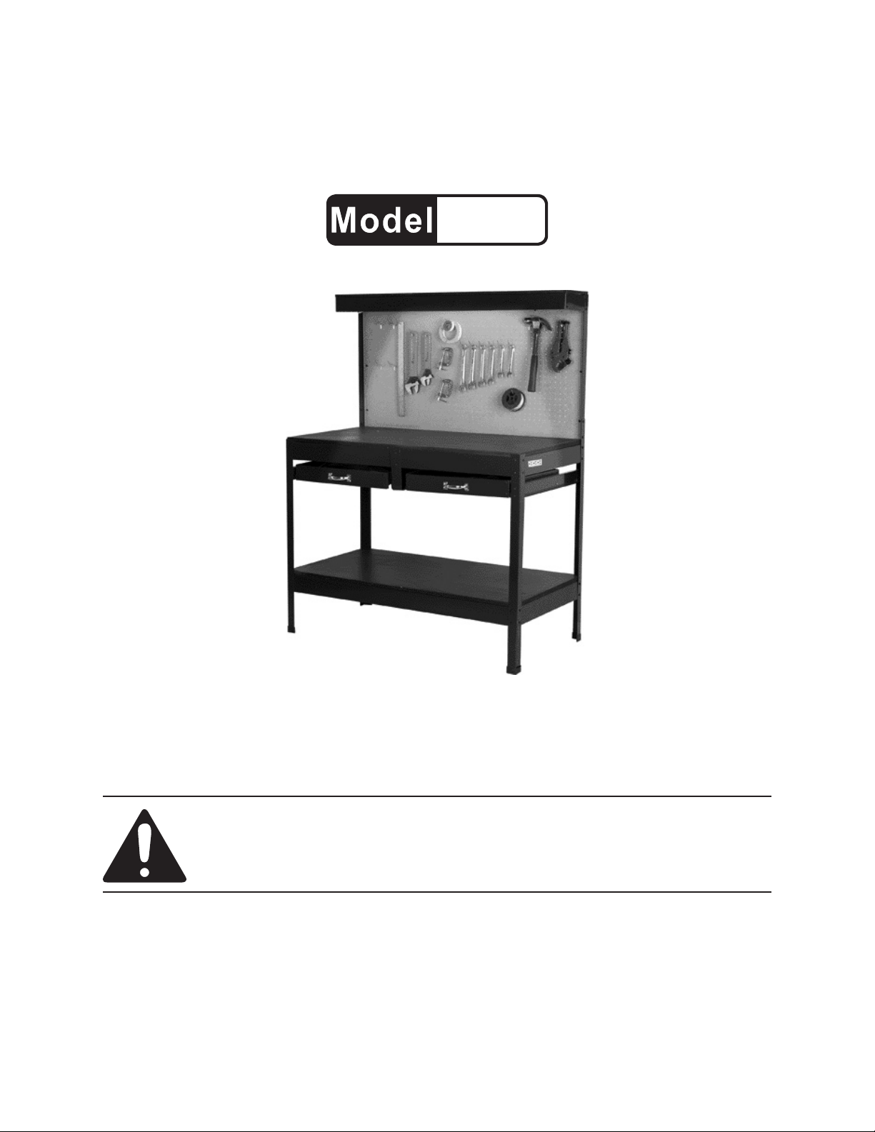
MULTI-PURPOSE WORKBENCH
WITH LIGHTING
99681
ASSEMBLY INSTRUCTIONS
Tools sold separately.
Distributed exclusively by Harbor Freight Tools®.
3491 Mission Oaks Blvd., Camarillo, CA 93011
Visit our website at: http://www.harborfreight.com
Read this material before using this product.
Failure to do so can result in serious injury.
SAVE THIS MANUAL.
Copyright© 2008 by Harbor Freight Tools®. All rights reserved. No portion of this manual or any artwork
contained herein may be reproduced in any shape or form without the express written consent of
Harbor Freight Tools. Diagrams within this manual may not be drawn proportionally. Due to continuing
improvements, actual product may differ slightly from the product described herein. Tools required for
assembly and service may not be included.
For technical questions or replacement parts, please call 1-800-444-3353.
Manual revised 08l
Page 2

SAVE THIS MANUAL
Keep this manual for the safety warnings and precautions, assembly, operating, inspection, maintenance and cleaning
procedures. Write the product’s serial
number in the back of the manual near the
assembly diagram (or month and year of
purchase if product has no number). Keep
this manual and the receipt in a safe and
dry place for future reference.
IMPORTANT SAFETY
INFORMATION
In this manual, on the labeling,
and all other information provided with this product:
This is the safety alert
symbol. It is used to alert
you to potential personal
injury hazards. Obey all
safety messages that
follow this symbol to avoid
possible injury or death.
NOTICE is used to
address practices
not related to personal injury.
CAUTION, without
the safety alert
symbol, is used to address
practices not related to
personal injury.
General Safety Warnings
WARNING Read all safety
warnings and instructions.
Failure to follow the warnings
and instructions may result in
electric shock, re and/or serious
injury. Save all warnings and
instructions for future reference.
Work area safety1.
Keep work area clean and well lit. a.
Cluttered or dark areas invite accidents.
Keep children and bystanders b.
away while operating a power tool.
Distractions can cause you to lose
control.
DANGER indicates
a hazardous
situation which, if not
avoided, will result in death or
serious injury.
WARNING
indicates a
hazardous situation which, if
not avoided, could result in
death or serious injury.
CAUTION, used
with the safety
alert symbol, indicates a
hazardous situation which, if
not avoided, could result in
minor or moderate injury.
SKU 99681 For technical questions, please call 1-800-444-3353. Page 2
Electrical safety2.
Power tool plugs must match the a.
outlet. Never modify the plug in
any way. Do not use any adapter
plugs with grounded power tools.
Unmodied plugs and matching outlets will reduce risk of electric shock.
Do not abuse the cord. Never use b.
the cord for unplugging the power
tool. Keep cord away from heat,
oil, sharp edges or moving parts.
Damaged or entangled cords increase the risk of electric shock.
Use personal protective equip-c.
ment. Always wear ANSI-approved
Page 3
safety goggles when assembling
this product.
Prevent unintentional starting. d.
Ensure the switch of the power
strip is in the off-position before
connecting to power source, and
plugging in any power tool.
SAVE THESE
INSTRUCTIONS.
Grounded Tools: Tools with Three
Prong Plugs
GROUNDING
TO PREVENT
ELECTRIC SHOCK
AND DEATH FROM
INCORRECT GROUNDING
WIRE CONNECTION:
Check with a qualied
electrician if you are in doubt
as to whether the outlet is
properly grounded. Do not
modify the power cord plug
provided with the tool. Never
remove the grounding prong
from the plug. Do not use the
tool if the power cord or plug
is damaged. If damaged, have
it repaired by a service facility
before use. If the plug will not
t the outlet, have a proper
outlet installed by a qualied
electrician.
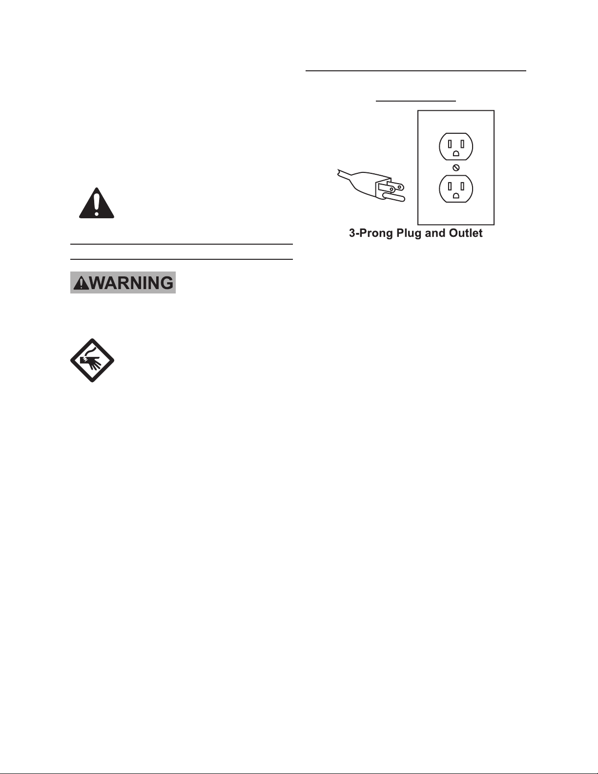
Tools marked with “Grounding Re-1.
quired” have a three wire cord and
three prong grounding plug. The
plug must be connected to a properly
grounded outlet. If the tool should
electrically malfunction or break
down, grounding provides a low
resistance path to carry electricity
away from the user, reducing the risk
of electric shock. (See 3-Prong Plug
and Outlet.)
The grounding prong in the plug is 2.
connected through the green wire inside the cord to the grounding system
in the tool. The green wire in the cord
must be the only wire connected to
the tool’s grounding system and must
never be attached to an electrically
“live” terminal. (See 3-Prong Plug
and Outlet.)
The tool must be plugged into an 3.
appropriate outlet, properly installed
and grounded in accordance with all
codes and ordinances. The plug and
outlet should look like those in the
preceding illustration. (See 3-Prong
Plug and Outlet.)
SKU 99681 For technical questions, please call 1-800-444-3353. Page 3
Page 4

Double Insulated Tools: Tools
with Two Prong Plugs
Tools marked “Double Insulated” do 1.
not require grounding. They have
a special double insulation system
which satises OSHA requirements
and complies with the applicable
standards of Underwriters Laboratories, Inc., the Canadian Standard
Association, and the National Electrical Code. (See Outlets for 2-Prong
Plug.)
Double insulated tools may be used 2.
in either of the 120 volt outlets shown
in the preceding illustration. (See
Outlets for 2-Prong Plug.)
The smaller the gauge number of the 3.
wire, the greater the capacity of the
cord. For example, a 14 gauge cord
can carry a higher current than a 16
gauge cord. (See Table A.)
When using more than one exten-4.
sion cord to make up the total length,
make sure each cord contains at
least the minimum wire size required.
(See Table A.)
If you are using one extension cord 5.
for more than one tool, add the
nameplate amperes and use the sum
to determine the required minimum
cord size. (See Table A.)
If you are using an extension cord 6.
outdoors, make sure it is marked with
the sufx “W-A” (“W” in Canada) to
indicate it is acceptable for outdoor
use.
Make sure the extension cord is prop-7.
erly wired and in good electrical condition. Always replace a damaged
extension cord or have it repaired by
a qualied electrician before using it.
Extension Cords
Grounded1. tools require a three wire
extension cord. Double Insulated
tools can use either a two or three
wire extension cord.
As the distance from the supply outlet 2.
increases, you must use a heavier
gauge extension cord. Using extension cords with inadequately sized
wire causes a serious drop in voltage,
resulting in loss of power and possible tool damage.
(See Table A.)
SKU 99681 For technical questions, please call 1-800-444-3353. Page 4
Protect the extension cords from 8.
sharp objects, excessive heat, and
damp or wet areas.
Page 5

RECOMMENDED MINIMUM WIRE
GAUGE FOR EXTENSION CORDS*
(120/240 VOLT)
EXTENSION CORD
NAMEPLATE
LENGTH
AMPERES
(at full load)
0 – 2.0 18 18 18 18 16
2.1 – 3.4 18 18 18 16 14
3.5 – 5.0 18 18 16 14 12
5.1 – 7.0 18 16 14 12 12
7.1 – 12.0 18 14 12 10 -
12.1 – 16.0 14 12 10 - -
16.1 – 20.0 12 10 - - -
TABLE A
25’
50’
75’
100’
* Based on limiting the line
voltage drop to ve volts at
150% of the rated amperes.
Symbology
150’
V~
A
n0 xxxx/min.
Double Insulated
Canadian Standards Association
Underwriters Laboratories, Inc.
Volts Alternating Current
Amperes
No Load Revolutions per Minute
(RPM)
SKU 99681 For technical questions, please call 1-800-444-3353. Page 5
Page 6

SPECIFICATIONS
Power Strip Rating 125 V~ / 7 A
Replacement Bulb T5 14W
550 lb. - evenly distributed
as follows:
Maximum Weight
Capacity
Bench Top - 250 lb.
Bottom shelf - 200 lb.
Each Drawer - 25 lb.
Top Shelf - 45 lb.
UNPACKING
When unpacking, make sure that the
item is intact and undamaged. If any parts
are missing or broken, please call Harbor
Freight Tools at the number shown on the
cover of this manual as soon as possible.
ASSEMBLY
Read the ENTIRE IMPORTANT
SAFETY INFORMATION
section at the beginning of this
manual including all text under
subheadings therein before set
up or use of this product.
Left Rear Post
Extension (2L)
23 22
Left Rear
Post (1L)
26
Fig. 1
1. Attach the Left Rear Post (1L) to the
Left Post Extension (2L) using Bolts
(26), Washers (22), and Nuts (23).
Attach the Right Rear Post (1R) with
the Right Post Extension (2R) using
Bolts (26), Washers (22), and Nuts
(23).
23
22
2R
1R
Note: For additional information regarding
the parts listed in the following pages,
refer to the Assembly Diagram near
26
Side with 10
holes facing
down
the end of this manual.
2L
1L
Fig. 2
NOTE:
With the two Rear Posts laying on
the oor, the sides with ten holes (2L
& 1L, 2R & 1R) should be facing the
oor.
SKU 99681 For technical questions, please call 1-800-444-3353. Page 6
Page 7

Side
Beam 8
Top Shelf
Rear
Beam 3
Drawer
Mounts 9
Side
Beam 8
Bottom
Beam 6
Center Beam
with Holes 5
Side
Beam 8
Right Front
Post 10R
Center Beam
with Holes 5
Left Front
Post 10L
24
22
27
26
23
22
Fig. 3
2. From top to bottom, connect the
top shelf Rear Beam (3), the Center
Beam with holes, in the middle (5),
and a Bottom Beam (6) onto the two
rear Legs using Bolts (26), Washers
(22), and Nuts (23).
NOTE: Only put one screw in the top hole
at each end of the Top Shelf Rear
Beam (3) at this stage. The bottom
hole will be used when the Peg Board
(17) is fastened in Step 7.
Using Bolts (26), Washers (22), and 3.
Nuts (23), attach two Side Beams (8)
onto the rear legs at the Center Beam
With Holes (5), to the back, and
another two Side Beams (8) at the
Bottom Beam (6).
Fig. 4
5. Attach the Left Front Post (10L) to
the Left Side Beam (8) and Drawer
Mount with Glide Rail (9), repeat with
the Right Front Post (10R). Attach
Center Beam With Holes (5), to the
front, using Bolts (26, 27), Washers
(22), and Nuts (23, 24). (See Fig. 4.)
At the bottom, attach the Left Front 6.
Post (10L) to the Left Side Beam (8)
and Bottom Beam (6) using Bolts
(26), Washers (22) and Nuts (23).
Repeat the procedure using the Right
Front Post (10R) for the right side.
Center Rear
“L” Bracket 12
27
27
Attach both Drawer Mounts With 4.
Glide Rails (9) below the two Side
Beams (8) using Bolts (27), Washers
(22), and Nuts (24).
24
22
Center Drawer
Glide Rail 13
Center Front
“L” Bracket 11
22
23
Mount with
Center Front
“L” Bracket 11
Fig. 5
7. Stand the frame upright. Fit the Center Front “L” Bracket (11) inside the
SKU 99681 For technical questions, please call 1-800-444-3353. Page 7
Page 8

Front Center Beam With Holes (5)
using Bolts (27), Washers (22), and
Nuts (24).
Attach the Center Drawer Mount With 8.
Glide Rail (13) to the two “L” Brackets
(11, 12) using Bolts (27), Washers
(22), and Nuts (23).
Top Shelf Left
Side Beam 7L
Top Shelf
Front Beam 4
Peg Board 17
27
Top Shelf Right
Side Beam 7R
22
23
Rear Plate of
Drawer 14R
23
Side Plate of
Drawer 15
Front Plate of Drawer 14F
Fig. 6
9. Attach the Front Plate of Drawer
(14F), Side Plates of Drawer (15),
and Rear Plate of Drawer (14R) together with Bolts (25) and Nuts (23).
Repeat for the second drawer. Do not 10.
tighten the screws on the “L” Brackets, Center Drawer Mount With Glide
Rail and two drawers until the two
drawers are t into the bench frame.
25
Fig. 7
11. Attach the Peg Board (17) to the
bottom holes of the Top Shelf Back
Beam (3) using Bolts (27), Washers
(22), and Nuts (23).
Attach two Top Shelf Side Beams (7L, 12.
7R) onto the Left & Right Post Extensions (2L, 2R) with Bolts (26), washers (22), and Nuts (23)
Attach the Top Shelf Front Beam (4) 13.
with Bolts (26), Washers (22), and
Nuts (23).
18
28
Fig 8
14. Place the Top Shelf (18), Bench Top
(19), Drawer Boards (20), and Bottom
Board (21) into position. Attach the
Top Shelf (18) using Wood Screws
(28).
SKU 99681 For technical questions, please call 1-800-444-3353. Page 8
Page 9

29
30
32
33
15. Insert a Slider Bolt (30) through each
of the Lamp Mounting Sliders (29).
32
30
29
16. Slide the Lamp Mounting Sliders (29)
into the slot at the top of the Lamp
(32), as shown above.
18. Attach the Lamp Power Cord (33) to
the receptacle at the end of the Lamp
(32). It will only connect one way.
18
30
17. Insert the ends of the Bolts (30)
through the holes underneath the Top
Shelf (18) and secure in place with
the Slider Nuts (31) from the top.
SKU 99681 For technical questions, please call 1-800-444-3353. Page 9
Page 10

MAINTENANCE AND
SERVICING
Procedures not specically
explained in this manual
must be performed only by a
qualied technician.
TO PREVENT
SERIOUS INJURY
FROM ACCIDENTAL
OPERATION:
Turn the Power Switch of the
power-strip to its “OFF”
position so that any power
tool plugged into it cannot be
accidentally turned on. Do
this before performing any
inspection, maintenance, or
cleaning procedures.
bulb up into the slots at the right and
left xture receptacles.
Rotate the bulb lengthwise 90º again d.
to seat the bulb. Replace the clear
cover.
5. WARNING! If the supply cord
of this workbench’s light or power
strip is damaged, it must be re-
placed only by a qualied service
technician.
BEFORE EACH USE,1. inspect the
general condition of the bench.
Check for loose screws, misalignment
or binding of moving parts, cracked or
broken parts, damaged electrical wiring, and any other condition that may
affect its safe operation.
AFTER USE,2. clean external surfaces
of the bench with clean cloth.
Vacuum Bench Top, wipe or brush 3.
clean.
The light xture mounted underneath 4.
the top shelf has a transparent plastic
cover over the bulb.
Gently pull straight down at both a.
ends of the cover and set aside.
Remove the bulb by spinning the b.
bulb 90º, rolling in a forward or backward direction and dropping the bulb
straight down.
With the prongs on either end of the c.
bulb vertically aligned, t the new
SKU 99681 For technical questions, please call 1-800-444-3353. Page 10
Page 11

PLEASE READ THE FOLLOWING CAREFULLY
THE MANUFACTURER AND/OR DISTRIBUTOR HAS PROVIDED THE PARTS LIST AND ASSEMBLY
DIAGRAM IN THIS MANUAL AS A REFERENCE TOOL ONLY. NEITHER THE MANUFACTURER OR
DISTRIBUTOR MAKES ANY REPRESENTATION OR WARRANTY OF ANY KIND TO THE BUYER THAT
HE OR SHE IS QUALIFIED TO MAKE ANY REPAIRS TO THE PRODUCT, OR THAT HE OR SHE IS
QUALIFIED TO REPLACE ANY PARTS OF THE PRODUCT. IN FACT, THE MANUFACTURER AND/
OR DISTRIBUTOR EXPRESSLY STATES THAT ALL REPAIRS AND PARTS REPLACEMENTS SHOULD
BE UNDERTAKEN BY CERTIFIED AND LICENSED TECHNICIANS, AND NOT BY THE BUYER. THE
BUYER ASSUMES ALL RISK AND LIABILITY ARISING OUT OF HIS OR HER REPAIRS TO THE
ORIGINAL PRODUCT OR REPLACEMENT PARTS THERETO, OR ARISING OUT OF HIS OR HER
INSTALLATION OF REPLACEMENT PARTS THERETO.
PARTS LIST
Part Description Qty.
1L Left Rear Post 1
1R Right Rear Post 1
2L Left Post Extension 1
2R Right Post Extension 1
3 Top Shelf Rear Beam 1
4 Top Shelf Front Beam 1
5 Center Beam With Holes 2
6 Bottom Beam 2
7L Top Shelf Left Side Beam 1
7R Top Shelf Right Side Beam 1
8 Side Beam 4
9 Drawer Mounts With Glide Rails 2
10L Left Front Post 1
10R Right Front Post 1
11 Center Front "L" Bracket 1
12 Center Rear "L" Bracket 1
13 Center Drawer Mount w/ Rail 1
14F Front Plates Of Drawer 2
14R Rear Plates Of Drawer 2
15 Side Plates Of Drawer 4
PARTS LIST
Part Description Qty.
16 Hooks 20
17 Peg Board 1
18 Top Shelf 1
19 Bench Top 1
20 Drawer Boards 2
21 Bottom Board 1
22 M6 Washers 72
23 M6 Nuts 76
24 M6 Lock Nuts 12
25 M6 x 8 mm Bolt 16
26 M6 x 10 mm Bolt 46
27 M6 x 18 mm Bolt 26
28 Wood Screws 6
29* Lamp Mounting Slider 2
30* Slider Bolt 2
31* Slider Nut 2
32* Lamp 1
33* Lamp Power Cord 1
*Not shown in diagram.
Record Product’s Serial Number Here:
Note: If product has no serial number, record month and year of purchase instead.
Note: Some parts are listed and shown for illustration purposes only, and are not avail-
able individually as replacement parts.
SKU 99681 For technical questions, please call 1-800-444-3353. Page 11
Page 12

ASSEMBLY DIAGRAM
SKU 99681 For technical questions, please call 1-800-444-3353. Page 12
 Loading...