

Page 1
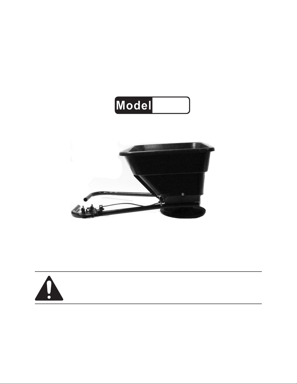
12 VOLT, 80 LB.
ATV SPREADER
99621
SET UP AND OPERATING INSTRUCTIONS
Distributed exclusively by Harbor Freight Tools®.
3491 Mission Oaks Blvd., Camarillo, CA 93011
Visit our website at: http://www.harborfreight.com
Read this material before using this product.
Failure to do so can result in serious injury.
SAVE THIS MANUAL.
Copyright© 2008 by Harbor Freight Tools®. All rights reserved. No portion of this manual or any artwork
contained herein may be reproduced in any shape or form without the express written consent of
Harbor Freight Tools. Diagrams within this manual may not be drawn proportionally. Due to continuing
improvements, actual product may differ slightly from the product described herein. Tools required for
assembly and service may not be included.
For technical questions or replacement parts, please call 1-800-444-3353.
Page 2

SAVE THIS MANUAL
Keep this manual for the safety warnings and precautions, assembly, operating, inspection, maintenance and cleaning
procedures. Write the product’s serial
number in the back of the manual near the
assembly diagram (or month and year of
purchase if product has no number). Keep
this manual and the receipt in a safe and
dry place for future reference.
NOTICE is used to
address practices
not related to personal injury.
CAUTION, without
the safety alert
symbol, is used to address
practices not related to
personal injury.
READ ALL
IMPORTANT SAFETY
INSTRUCTIONS
In this manual, on the labeling,
and all other information
provided with this product:
This is the safety alert
symbol. It is used to alert
you to potential personal
injury hazards. Obey all
safety messages that
follow this symbol to avoid
possible injury or death.
DANGER indicates
a hazardous
situation which, if not
avoided, will result in death or
serious injury.
WARNING
indicates a
hazardous situation which, if
not avoided, could result in
death or serious injury.
INSTRUCTIONS
Personal Safety
CAUTION:
To prevent injury:
Read ATV/mower manual before 1.
installation.
Wear ANSI-approved safety goggles 2.
and heavy-duty work gloves during
installation and use. Use of face or
dust mask is recommended if operation is dusty.
Keep clear of Turning Plate (16) dur-3.
ing use.
Keep out of reach of children.4.
Secure Spreader attachment before 5.
use.
Replace fuse only with same type 6.
and rating.
Use for intended purposes only. Do 7.
not use for hauling.
CAUTION, used
with the safety
alert symbol, indicates a
hazardous situation which, if
not avoided, could result in
minor or moderate injury.
SKU 99621 For technical questions, please call 1-800-444-3353. Page 2
Dress Properly - Do not wear loose 8.
clothing or jewelry. They can be
caught in moving parts. Wear protective hair covering to contain long hair.
Page 3

9. Wear thick jeans and
steel-toed work boots to
help prevent injury
caused by ying debris.
Never attempt to install this ATV 3.
Spreader to the ATV vehicle alone.
Have another adult assist when attaching or detaching.
Stay alert - Watch what you are 10.
doing. Use common sense. Do not
operate ATV Spreader when you are
tired.
11. Do not grasp the exposed
Turning Plate (16) edges
when picking up or holding the Spreader.
Do not Use In Rain, or damp loca-12.
tions.
All visitors should be kept at a dis-13.
tance from work area.
When servicing use only identical 14.
replacement parts.
Store Idle ATV Spreader Indoors, out 15.
of reach of children.
Maintain ATV Spreader With Care. 16.
Follow instructions for lubrication.
Check for damaged parts. If anything
irregular is found, the damage should
be properly repaired by a qualied
technician unless indicated elsewhere in this manual.
Refer to the material packaging, or 4.
bag safety instructions when handling
all materials to be applied with this
Spreader.
Before attaching this ATV Spreader, 5.
consideration must be given to the
load capacity of the vehicle to be
loaded. Be sure to account for the
weight of this Spreader and the
weight of the material being spread.
Maintain labels and nameplates on 6.
the appliance. These carry important
safety information. If unreadable or
missing, contact Harbor Freight Tools
for a replacement.
The warnings, precautions, and in-7.
structions discussed in this instruction
manual cannot cover all possible conditions and situations that may occur.
It must be understood by the operator
that common sense and caution are
factors which cannot be built into this
product, but must be supplied by the
operator.
Disconnect the ATV Spreader when 17.
not in use and/or before servicing.
Specic Safety Rules
Care must be taken when lifting this 1.
ATV Spreader so as not to cause
equipment damage and/or personal
injury.
Remove any material in Hopper As-2.
sembly (8) before removing this ATV
Spreader from the vehicle.
SKU 99621 For technical questions, please call 1-800-444-3353. Page 3
Hopper
Assembly
Capacity
Drive Motor 12V Electric
SAVE THESE
INSTRUCTIONS.
SPECIFICATIONS
80 LB. Weight capacity.
1900 cu. in. Storage capacity
Page 4

UNPACKING
When unpacking, check to make sure
that the item is intact and undamaged. If
any parts are missing or broken, please
call Harbor Freight Tools at the number
shown on the cover of this manual as soon
as possible.
SET UP INSTRUCTIONS
Read the ENTIRE IMPORTANT
SAFETY INSTRUCTIONS
section at the beginning of this
manual including all text under
subheadings therein before set
up or use of this product.
Note: For additional information regarding
the parts listed in the following pages,
refer to the Assembly Diagram near
the end of this manual.
Assembly
The ATV Spreader comes partially 1.
assembled.
Mount the two sides of the Frame 2.
Rail (21) to the Hopper Assembly (8)
using Screws M5 x 35 (14).
Position the Gauge Assembly (22) 3.
to either Frame Rail (21) based on
whether the Hopper Assembly (8) is
to be mounted on the front, or rear
rack of the ATV. If mounted on the
rear rack, the Control Handle (25)
should be on the right Frame Rail
(21). If mounted on the front rack,
place the Control Handle (25) on the
Left Frame Rail (21). See Figure 1
below.
Figure 1
Switch Box Installation:
WARNING: To prevent serious injury,
make sure the ATV is OFF before installing The Switch Box Assembly (31) .
Attach the Switch Box Assembly (31) 1.
to your ATV. Route cable ties through
the two slots located on the Switch
Box Assembly (31) and connect them
onto the ATV Frame.
NOTE: Make sure the Switch Box Assembly (31) is secure before proceeding.
Connect the ATV Battery Terminals 2.
(31-3) to battery. Connect the white
wire to the battery’s positive pole,
connect the black wire to the battery’s
negative pole .
Connect the Motor Terminal (31-4) to 3.
the Electric Motor (3) terminal.
Connect the ATV Battery Terminals 4.
(31-3) to the Motor Assembly using
the Harness Connector. See parts list
and assembly diagram page 7 and 8.
REV 08g; 09a
SKU 99621 For technical questions, please call 1-800-444-3353. Page 4
Page 5

How to Attach to your ATV
Place the ATV Spreader (assembled), 1.
centered on the front, or rear luggage
rack of your ATV. Use the J-Bolts
(34), Press Plate (33) and Hex Nuts
(32) to connect Frame Rail (21) to the
luggage rack cross bar closest to the
seat, or handlebars. Use the J-Bolts
(34), Press Plate (33) and Hex Nuts
(32) to attach the Spreader to the
luggage rack, securing it to the outer
most rail on the luggage rack.
WARNING:2. Prior to each use, inspect
the mounting hardware and the ATV
Spreader to ensure the tightness of
the mount. If any hardware is loose,
tighten securely before using the unit.
Functions
This ATV Spreader can be used to 1.
spread grass seed, fertilizer pellets,
sand, ice-melt and any other type of
seed or loose pellet type lawn care
products.
NOTE:2. Not for powdered lawn prod-
ucts which are hard to adjust spread
rates, or for heavy, mulch-type prod-
ucts which will clog the Turning Plate
(16).
An Adjustable Solid Stop is provided 2.
to allow the operator to adjust the
Gauge Assembly (22) to the desired
opening, allowing the correct amount
of material to fall onto the Turning
Plate (16) for disbursement. The
“Solid Stop” will allow the operator to
repeat the opening/closing without
having to look at the control while operating the vehicle. It is set by using
the Thumb Wing Nut (24) located on
the Gauge Assembly (22). Establish
the correct opening, then lock down
the Thumb Wing Nut (24).
Measure off a distance of 50 feet on 3.
the surface you will be working. See
number 9 below.
Weight out enough of the material to 4.
ll the Hopper Assembly (8) at least
half full. Record the weight for further
use.
Set the Adjustable Solid Stop on the 5.
Gauge Assembly (22) to the desired
opening and tighten the Thumb Wing
Nut (24).
NOTE:6. Usually an approximate
spreading rate is listed in material di-
rections, or on the bag of the specic
material you will use.
As you start driving the ATV through 7.
OPERATING INSTRUCTIONS
Read the ENTIRE IMPORTANT
SAFETY INFORMATION section
at the beginning of this manual
including all text under
subheadings therein before set
up or use of this product.
Before operating the ATV Spreader, 1.
put on ANSI-approved safety goggles
and other safety gear (not supplied).
SKU 99621 For technical questions, please call 1-800-444-3353. Page 5
the work area, open the Control
Handle (25) till it stops against the
Adjustable Solid Stop.
Continue to spread the material till 8.
you cross the end of the area you are
working. Close the Control Handle
(25) to stop the ow of material onto
the Turning Plate (16).
Page 6

Empty the Hopper Assembly and 9.
re-weigh the material. By taking note
of how much material you used and
how wide the spreading area was,
you can gure the correct rate of
spread. This will help you maintain
the correct spreading rate for your
project.
er. Check for loose screws, misalignment or binding of moving parts,
cracked or broken parts, damaged
electrical wiring, and any other condition that may affect its safe operation.
AFTER USE,2. clean external surfaces
with clean, moist cloth.
To prevent accidents, turn off the ATV 10.
and disconnect the ATV Spreader
after use. Clean, then store indoors
out of children’s reach.
MAINTENANCE AND
SERVICING
Procedures not specically
explained in this manual
must be performed only by a
qualied technician.
TO PREVENT
SERIOUS INJURY
FROM ACCIDENTAL
OPERATION:
Turn the Power Switch of the
vehicle to its “OFF” position
before performing any
inspection, maintenance, or
cleaning procedures.
TO PREVENT SERIOUS
INJURY FROM TOOL
FAILURE:
Do not use damaged
equipment. If abnormal noise
or vibration occurs, have the
problem corrected before
further use.
Cleaning, Maintenance, and
Lubrication
BEFORE EACH USE,1. inspect the
general condition of the ATV Spread-
Clean out the Hopper Assembly and 3.
using a shop vacuum (not supplied),
clear all leftover material from the
Turning Plate (16) and other areas of
the Spreader.
Rinse the ATV Spreader with a hose 4.
and fresh clear water. Let dry before
storing indoors away from children.
NOTE: 5. If the ATV Spreader is to be
left outside between jobs, always
cover with the Rain Cover (1) to
protect both the Spreader and any
material that may be in the Hopper
Assembly (8).
PLEASE READ THE FOLLOWING
CAREFULLY
THE MANUFACTURER AND/OR DISTRIBUTOR
HAS PROVIDED THE PARTS LIST AND ASSEMBLY
DIAGRAM IN THIS MANUAL AS A REFERENCE
TOOL ONLY. NEITHER THE MANUFACTURER OR
DISTRIBUTOR MAKES ANY REPRESENTATION
OR WARRANTY OF ANY KIND TO THE BUYER
THAT HE OR SHE IS QUALIFIED TO MAKE ANY
REPAIRS TO THE PRODUCT, OR THAT HE OR
SHE IS QUALIFIED TO REPLACE ANY PARTS OF
THE PRODUCT. IN FACT, THE MANUFACTURER
AND/OR DISTRIBUTOR EXPRESSLY STATES
THAT ALL REPAIRS AND PARTS REPLACEMENTS
SHOULD BE UNDERTAKEN BY CERTIFIED AND
LICENSED TECHNICIANS, AND NOT BY THE
BUYER. THE BUYER ASSUMES ALL RISK AND
LIABILITY ARISING OUT OF HIS OR HER REPAIRS
TO THE ORIGINAL PRODUCT OR REPLACEMENT
PARTS THERETO, OR ARISING OUT OF HIS OR
HER INSTALLATION OF REPLACEMENT PARTS
THERETO.
SKU 99621 For technical questions, please call 1-800-444-3353. Page 6
Page 7

Troubleshooting
Problem Possible Causes Likely Solutions
Control Handle will
not open/close Gauge
Assembly.
Material not spreading
at proper rate.
Material clogging port of Gauge 1.
Assembly (22) and/or Adjustment
Plate (13).
Wrong opening on Gauge Assembly 1.
(22).
Check both Gauge Assembly (22) 1.
and Adjustment Plate (13) and clear
debris if necessary.
Loosen Thumb Wing Nut (24) and 1.
open/close accordingly and readjust if necessary.
Follow all safety precautions whenever diagnosing or servicing the
appliance. Turn off ATV and remove Spreader from vehicle before
service.
PARTS LIST
Part # Description Q’ty Part # Description Q’ty
1 Rain Cover 1 20 Hex Bolt M6X30 1
2 Electric Motor Lid 1 21 Frame Rail 2
3 Electric Motor 1 22 Gauge Assembly 1
4 Electric Motor Cover 1 23 Spacer 1
5 Tie 1 24 Thumb Wing Nut M6 2
6 Unlock Nut 2 25 Control Handle 1
7 Motor Support 1 26 Wire Adjustment Clip B 1
8 Hopper Assembly 1 27 Wood Screw M4.5X18 2
9 Flat Washer 4 28 Adjustment Wire 1
10 Hex Bolt M6X15 2 29 Phillips Screw M6X15 2
11 Wire Clamp 1 30 Lock Washer 2
12 Wire Adjustment Clip A 1 31 Switch Box Assembly 1
13 Adjustment Plate 1 31-1 Fuse 1
14 Screw M5X35 4 31-2 Switch 1
15 Center Spacer 1 31-3 ATV Battery Terminals 1
16 Turning Plate 1 31-4 Motor Terminal 1
17 Wood Screw M4.5X10 3 32 Hex Nut M6 8
18 Phillips Screw M4X20 1 33 Press Plate 4
19 Phillips Screws M6X45 1 34 J-Bolt 8
Record Product’s Serial Number Here:
Note: If product has no serial number, record month and year of purchase instead.
Note: Some parts are listed and shown for illustration purposes only, and are not avail-
able individually as replacement parts.
REV 08g
SKU 99621 For technical questions, please call 1-800-444-3353. Page 7
Page 8

ASSEMBLY DIAGRAM
Harness
Connector
REV 08g
SKU 99621 For technical questions, please call 1-800-444-3353. Page 8
 Loading...