

Harbor Freight Tools 98568 Product manual
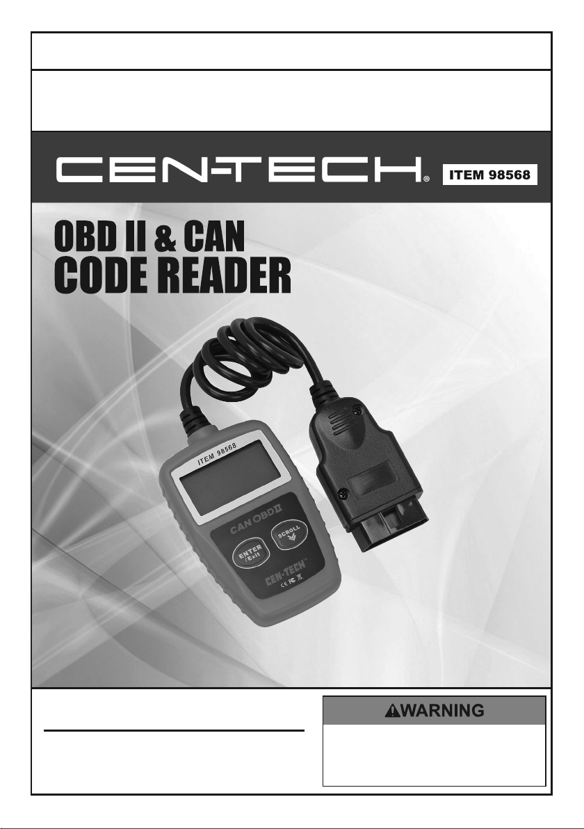
Owner’s Manual & Safety Instructions
Save This Manual Keep this manual for the safety warnings and precautions, assembly,
operating, inspection, maintenance and cleaning procedures. Write the product’s serial number in the
back of the manual near the assembly diagram (or month and year of purchase if product has no number).
Keep this manual and the receipt in a safe and dry place for future reference.
REV 14e
When unpacking, make sure that the product is intact
and undamaged. If any parts are missing or broken,
please call 1-888-866-5797 as soon as possible.
Copyright© 2008 by Harbor Freight Tools®. All rights reserved.
No portion of this manual or any artwork contained herein may be reproduced in
any shape or form without the express written consent of Harbor Freight Tools.
Diagrams within this manual may not be drawn proportionally. Due to continuing
improvements, actual product may differ slightly from the product described herein.
Tools required for assembly and service may not be included.
Email our technical support at: productsupport@harborfreight.com
Visit our website at: http://www.harborfreight.com
Read this material before using this product.
Failure to do so can result in serious injury.
SAVE THIS MANUAL.

Table of Contents
1. Safety Precautions and Warnings.......................................1
2. General Information ............................................................2
2.1 On-Board Diagnostics (OBD) II...............................2
2.2 Diagnostic Trouble Codes (DTCs) ...........................2
2.3 Location of the Data Link Connector (DLC)..........3
2.4 OBD II Readiness Monitors .....................................4
2.5 OBD II Monitor Readiness Status ...........................5
2.6 OBD II Definitions.....................................................6
3. Using the Code Reader.........................................................8
3.1 Tool Description ........................................................8
3.2 Specifications .............................................................9
3.3 Accessories Included .................................................9
3.4 Navigation Characters ..............................................9
3.5 Vehicle Power.............................................................9
3.6 Product Setup...........................................................10
3.7 Vehicle Coverage .....................................................13
4. OBD II Diagnostics.............................................................14
4.1 Reading Codes .........................................................15
4.2 Erasing Codes ..........................................................16
4.3 Viewing Freeze Frame Data ...................................17
4.4 Retrieving I/M Readiness Status............................19
4.5 Viewing Vehicle Information..................................22
4.6 Exiting OBDII Test .................................................23
5. Warranty and Service ........................................................25

1. Safety Precautions and Warnings
To prevent personal injury or damage to vehicles and/or the code
reader, read this instruction manual first and observe the
following safety precautions at a minimum whenever working on
a vehicle:
z Always perform
z Wear safety eye prot
z Keep clothing, hair, hands, tools, test equipment, etc. away from
all movin
z Operate the
are poisonous.
z Put b
z Use extreme cauti
z Put the transmission in PARK (for automatic transmission) or
z K
z Don’t
z Keep t
z WARNING:
chemical known to the State of California to cause cancer and birth
defects or other reproductive harm. (California Health & Safety Code
§ 25249.5, et seq.)
locks in front of the drive wheels and never leave the vehicle
unatte
nded while running tests.
distributor cap, ignition wires and spark plugs. These components
create hazardous voltages when the e
NE
UTRAL (for manual transmission) and make sure the parking
brake is engaged.
eep a fire extinguisher suitable for gasoline/chemical/ electrical
fires nearby.
connect or disconnect any test equipment while the ignition
or the engine is running.
is on
he code reader dry, clean, free from oil/water or grease. Use
a m
ild detergent on a clean cloth to clean the outside of the code
reader, when
automo
g or hot engine parts.
vehic
necessary.
This product contains or, when used, produces a
tive testing in a safe environment.
ection that meets ANSI standards.
le in a well ventilated work area: Exhaust gases
on when working around the ignition coil,
ngine
is running.
FCC Statement:
This device complies with Part 15 of the FCC Rules. Operation is subject
to the following two conditions: (1) this device may not cause harmful
interference, and (2) this device must accept any interference received,
including interference that may cause undesired operation.
1

2. General Information
2.1 On-Board Diagnostics (OBD) II
The first generation of On-Board Diagnostics (called OBD I) was
developed by the California Air Resources Board (ARB) and
implemented in 1988 to monitor some of the emission control
components on vehicles. As technology evolved and the desire to
improve the On-Board Diagnostic system increased, a new generation of
On-Board Diagnostic system was developed. This second generation of
On-Board Diagnostic regulations is called "OBD II".
The OBD II system is designed to monitor emission control systems
and key engine components by performing either continuous or
periodic tests of specific components and vehicle conditions. When a
problem is detected, the OBD II system turns on a warning lamp (MIL)
on the vehicle instrument panel to alert the driver typically by the
phrase of “Check Engine” or “Service Engine Soon”. The system will
also store important information about the detected malfunction so that
a technician can accurately find and fix the problem. Here below
follow three pieces of such valuable information:
1) Whether the Malfunction Indicator Light (MIL) is
commanded 'on' or 'off';
2) Which, if an
3) Readiness Monitor status.
y, Diagnostic Trouble Codes (DTCs) are stored;
2.2 Diagnostic Trouble Codes (DTCs)
OBD II Diagnostic Trouble Codes are codes that are stored by the
on-board computer diagnostic system in response to a problem found
in the vehicle. These codes identify a particular problem area and are
intended to provide you with a guide as to where a fault might be
occurring within a vehicle. OBD II Diagnostic Trouble Codes consist
of a five-digit alphanumeric code. The first character, a letter,
identifies which control system sets the code. The other four characters,
all numbers, provide additional information on where the DTC
originated and the operating conditions that caused it to set. Here
below is an example to illustrate the structure of the digits:
2
y
DTC Example
P0202
Systems
B=Body
C=Chassis
P=Powertrain
U=Network
Code Type
Generic (SAE):
P0, P2, P34-P39
B0, B3
C0, C3
U0, U3.
Manufacturer Specific:
P1, P30-p33
B1, B2
C1, C2
U1, U2
Identifying specific
malfunctioning
section of the
stems
s
Sub-systems
1= Fuel and Air Metering
2= Fuel and Air Metering
3= Ignition System or Engine Misfire
4= Auxiliary Emission Controls
5= Vehicle Speed Control and Idle
Controls
6= Computer Output Circuits
7= Transmission Controls
8= Transmission Controls
2.3 Location of the Data Link Connector (DLC)
The DLC (Data Link Connector or Diagnostic Link Connector) is the
standardized 16-cavity connector where diagnostic code readers
interface with the vehicle's on-board computer. The DLC is usually
located 12 inches from the center of the instrument panel (dash), under
or around the driver’s side for most vehicles. If Data Link Connector is
not located under dashboard, a label should be there telling location.
For some Asian and European vehicles, the DLC is located behind the
ashtray and the ashtray must be removed to access the connector. If the
DLC cannot be found, refer to the vehicle’s service manual for the
location.
3

2.4 OBD II Readiness Monitors
An important part of a vehicle’s OBD II system is the Readiness
Monitors, which are indicators used to find out if all of the emissions
components have been evaluated by the OBD II system. They are
running periodic tests on specific systems and components to ensure
that they are performing within allowable limits.
Currently, there are eleven OBD II Readiness Monitors (or I/M
Monitors) defined by the U.S. Environmental Protection Agency
(EPA). Not all monitors are supported by all vehicles and the exact
number of monitors in any vehicle depends on the motor vehicle
manufacturer’s emissions control strategy.
Continuous Monitors -- Some of the vehicle components or systems
are continuously tested by the vehicle’s OBD II system, while others
are tested only under specific vehicle operating conditions. The
continuously monitored components listed below are always ready:
1)Misfire
2)Fuel System
3)Comprehensive Components (CCM)
Once the vehicle is running, the OBD II system is continuously
checking the above components, monitoring key engine sensors,
watching for engine misfire, and monitoring fuel demands.
Non-Continuous Monitors -- Unlike the continuous monitors, many
emissions and engine system components require the vehicle to be
4

operated under specific conditions before the monitor is ready. These
monitors are termed non-continuous monitors and are listed below:
1) EGR System
2) O2 Sensors
3) Catalyst
4) Evaporative System
5) O2 Sensor Heater
6) Secondary air
7) Heated Catalyst
8) A/C system
2.5 OBD II Monitor Readiness Status
OBD II systems must indicate whether or not the vehicle’s PCM’s
monitor system has completed testing on each component.
Components that have been tested will be reported as “Ready”, or
“Complete”, meaning they have been tested by the OBD II system. The
purpose of recording readiness status is to allow inspectors to
determine if the vehicle’s OBD II system has tested all the components
and/or systems.
The powertrain control module (PCM) sets a monitor to “Ready” or
“Complete” after an appropriate drive cycle has been performed. The
drive cycle that enables a monitor and sets readiness codes to “Ready”
varies for each individual monitor. Once a monitor is set as “Ready” or
“Complete”, it will remain in this state. A number of factors, including
erasing of diagnostic trouble codes (DTCs) with a code reader or a
disconnected battery, can result in Readiness Monitors being set to
“Not Ready”. Since the three continuous monitors are constantly
evaluating, they will be reported as “Ready” all of the time. If testing of
a particular supported non-continuous monitor has not been completed,
the monitor status will be reported as “Not Complete” or “Not Ready.”
In order for the OBD monitor system to become ready, the vehicle
should be driven under a variety of normal operating conditions. These
operating conditions may include a mix of highway driving and stop
and go, city type driving, and at least one overnight-off period. For
specific information on getting your vehicle’s OBD monitor system
ready, please consult your vehicle owner’s manual.
5

2.6 OBD II Definitions
Powertrain Control Module (PCM) -- OBD II terminology for the
on-board computer that controls engine and drive train.
Malfunction Indicator Light (MIL) -- Malfunction Indicator Light
(Service Engine Soon, Check Engine) is a term used for the light on the
instrument panel. It is to alert the driver and/or the repair technician
that there is a problem with one or more of vehicle's systems and may
cause emissions to exceed federal standards. If the MIL illuminates
with a steady light, it indicates that a problem has been detected and the
vehicle should be serviced as soon as possible. Under certain
conditions, the dashboard light will blink or flash. This indicates a
severe problem and flashing is intended to discourage vehicle
operation. The vehicle onboard diagnostic system can not turn the MIL
off until the necessary repairs are completed or the condition no longer
exists.
DTC -- Diagnostic Trouble Codes (DTC) that identify which section
of the emission control system has malfunctioned.
Enabling Criteria -- Also termed Enabling Conditions. They are the
vehicle-specific events or conditions that must occur within the engine
before the various monitors will set, or run. Some monitors require
the vehicle to follow a prescribed “drive cycle” routine as part of the
enabling criteria. Drive cycles vary among vehicles and for each
monitor in any particular vehicle.
OBD II Drive Cycle -- A specific mode of vehicle operation that
provides conditions required to set all the readiness monitors
applicable to the vehicle to the “ready” condition. The purpose of
completing an OBD II drive cycle is to force the vehicle to run its
onboard diagnostics. Some form of a drive cycle needs to be performed
after DTCs have been erased from the PCM’s memory or after the
battery has been disconnected. Running through a vehicle’s complete
drive cycle will “set” the readiness monitors so that future faults can be
detected. Drive cycles vary depending on the vehicle and the monitor
that needs to be reset. For vehicle specific drive cycle, consult the
vehicle’s Owner’s Manual.
6

Freeze Frame Data -- When an emissions related fault occurs, the
OBD II system not only sets a code but also records a snapshot of the
vehicle operating parameters to help in identifying the problem. This
set of values is referred to as Freeze Frame Data and may include
important engine parameters such as engine RPM, vehicle speed, air
flow, engine load, fuel pressure, fuel trim value, engine coolant
temperature, ignition timing advance, or closed loop status.
7
 Loading...