

Page 1
800 LB. LOAD CAPACITY
PICKUP TRUCK RACK
Model
98511
INSTRUCTIONS AND PRECAUTIONS
Visit our website at: http://www.harborfreight.com
Read this material before using this product.
Failure to do so can result in serious injury.
SAVE THIS MANUAL.
Copyright© 2008 by Harbor Freight Tools®. All rights reserved. No portion of this manual or any artwork
contained herein may be reproduced in any shape or form without the express written consent of Harbor
Freight Tools. Diagrams within this manual may not be drawn proportionally. Due to continuing improvements, actual product may differ slightly from the product described herein. Tools required for assembly
and service may not be included.
For technical questions or replacement parts, please call 1-800-444-3353.
Manual Revised 10h
Page 2

SPECIFICATIONS
Materials
Max. Weight Capacity 800 lb.
Overall Dimensions 11’-6” L x 5’ W x 2’-10” H
Weight 133 lb.
Steel Tubing, Brackets and
Fasteners
UNPACKING
When unpacking, check to make sure that
the item is intact and undamaged. If any parts are
missing or broken, please call Harbor Freight Tools
at the number shown on the cover of this document
as soon as possible.
GENERAL SAFETY RULES
SAVE THESE INSTRUCTIONS
Do not exceed the 800 lb. max. weight ca-1.
pacity. Be aware of dynamic loading! Sud-
denly swinging or dropping load may briey
create excess load causing product failure.
Wear ANSI-approved safety goggles and 2.
heavy-duty work gloves during assembly and
installation.
Do not assemble without assistance; more 3.
than one person needed to successfully as-
semble and install Truck Rack.
Follow DOT regulations regarding Truck 4.
Rack installation and use.
Mount securely to vehicle. Mounting surface 5.
must be able to support Rack and its load.
Mount load securely to Rack before driving 6.
vehicle.
Before installing, check to see if vehicle has 7.
a long bed or a short bed. Setup depends on
truck bed size.
Install to vehicle only when vehicle is parked 8.
on a level surface, emergency brake acti-
vated, and ignition turned off. Do NOT install
Rack while vehicle is moving.
Use Truck Rack for intended purposes only. 9.
There are certain applications for which this
Truck Rack was designed. Do not modify
Truck Rack and do not use for a purpose for
which it was not intended.
Dress properly. Do not wear loose clothing 10.
or jewelry during assembly and installation
as they can be caught in connections. Wear
restrictive hair covering to contain long hair.
Maintain Truck Rack with care. Keep Truck 11.
Rack clean and dry.
Check for damaged components. Before us-12.
ing the Truck Rack, any component that appears damaged should be carefully checked
to determine that it will operate properly
and perform its intended function. Check
for alignment, any broken parts or mounting
xtures; and any other condition that may affect proper operation. Any component that is
damaged should be replaced. Do NOT use if
parts are loose or damaged.
Read manual of power drill used before 13.
installing.
When servicing, use only identical replace-14.
ment parts. Use of any other parts will void
the warranty.
Verify that installation surfaces on vehicle 15.
have no hidden wires before drilling or driving screws.
Mount only to vehicle able to withstand 16.
weight of Truck Rack and items stored on
Rack.
Do not allow children to play with or climb on 17.
Truck Rack.
The warnings, precautions, and instructions 18.
discussed in this instruction manual cannot
cover all possible conditions and situations
that may occur. It must be understood by the
operator that common sense and caution are
factors which cannot be built into this product, but must be supplied by the operator.
Read the ENTIRE IMPORTANT
SAFETY INFORMATION section at the
beginning of this document including
all text under subheadings therein
before set up or use of this product.
Note: For additional information
regarding the parts listed in the following
pages, refer to the Assembly Diagrams
shown for each individual item number
over the next few pages.
REV 08h, 10b
SKU 98511 For technical questions, please call 1-800-444-3353. Page 2
Page 3
Assembly
Please note: The following tools are needed
(but not included) for proper assembly of
Truck Rack: Adjustable Wrench, Hacksaw,
Pen Marker, Center Punch and a Drill with
5/16” Drill bit.
Before assembly and installation, determine 1.
if truck has LONG or SHORT bed. Measure
length of truck bed with tailgate closed. Then
measure between Truck Rack’s Front and
Rear Leg Stands. Proper assembly depends
on knowing correct bed truck size.
Please note:2. During assembly, do not fully
tighten connections until specied.
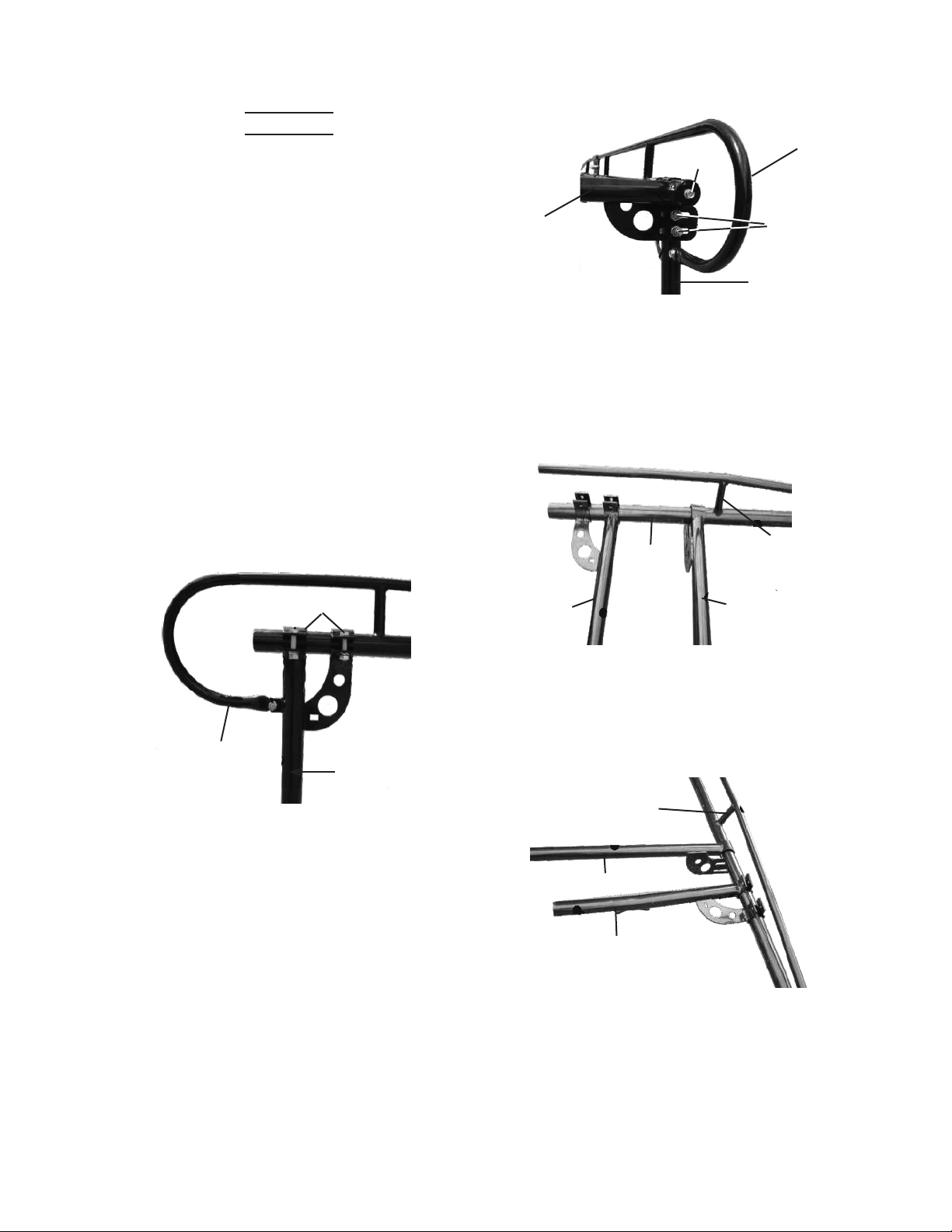
Slide Rear Leg Stands (6, 7) into curved rail 3.
ends of Back Side Frames (3). Using wrench
(not included) fasten together with Bolts
(18), Nuts (19) and Flat Washers (20). See
Figure 1, below.
Back Side
Frame (3)
Slide each end of Rear Bar (12) over top 4.
ends of Back Side Frames. Fasten together
using Bolts (18), Nuts (19) and Flat Washers
(20). See Figure 2, above.
Thread Bolt (31) and Washer (34) through 5.
Rear Leg Stands (6, 7) and out from rear leg
bar bracket slots. Attach Washer (34) and
Nut (32) and then nger tighten. Repeats
these steps for the opposite side. See Fig-
ure 2, above.
Bolts (18)
Rear Leg
Stand (6)
Figure 1
Rear Bar
(12)
Figure 2
The next step depends on bed truck size: 6.
For Short Bed Truck (5’- 7’ Long): Slide
Front Bar (10) onto BACK ends of Front Side
Frames (2). Then slide Front Leg Stands
(4, 5) onto Front Side Frames so they are
behind Front Frame’s cross bar. See Figure
3, below.
Front Leg
Stand (4)
For Long Bed Truck (7’ or more): Slide
Front Bar (10) onto FRONT ends of Front
Side Frames (2). Then slide Front Leg
Stands (4) onto Front Side Frames so they
are in front of Frame’s cross bar. See Figure
4, below.
7. Fasten Front Leg Stands (4, 5) to Front Side
Frames (2), using Bolts (18), Nuts (19), and
Flat Washers (20).
8. Use Bolts (31), Nuts (32), Spring Washers
(33), and Flat Washers (34) to connect Leg
Stands (4, 5) to Front Bar (10).
Cross Bar
Front Bar (10)
Front Leg Stand (4)
Bolts (21)
Front
Side
Frame (2)
Figure 3
Figure 4
Back Side
Frame (3)
Bolts (31)
Rear Leg
Stand (6)
Cross Bar
Front Bar
(10)
REV 10c
SKU 98511 For technical questions, please call 1-800-444-3353. Page 3
Page 4

9. Slide Front Side Frames (2) and Back Side
Frames (3) together. Attach two Clamp
halves (13) over connected portion of the
Side and Back frames. Use Bolts (15), Nuts
(16) and Flat Washers (17) to fasten Clamps
over connected frames. See Figure 5, below.
Clamps (13)
Back Side Frame (3)
Front Side
Frame (2)
Figure 5
to bottom of each Leg Stand using Bolts
(27), Nuts (28), Spring Washers (29) and Flat
Washers (30). See Figure 8, below.
Leg Stand
Bolt (43)
Figure 8
Coupler Riser (14)
Mounting
Foot (8R, 9L)
10. Slide ends of Cab Bar (1) over ends of Front
Side Frames. Fasten Cab Bar to Frame tips
using Bolts (35), Nuts (36), Spring Washers
(37) and Flat Washers (38). See Figure 6,
below.
Cab Bar (1)
Bolt (35)
Front Side Frame (2)
Figure 6
Nut (36)
11. Place Center Bar (11) between Front or Rear
Side Frames. Please note: Center Bar is
adjustable and can be fastened anywhere
along Side Frames. Fasten Center Bar to
Side Frames using Bolts (24), Nuts (25) and
Flat Washers (26). See Figure 7, below.
Center Bar (11)
Clamps (13)
Figure 7
12. The Truck Rack comes with four Coupler Risers (14) that allow you to raise height of Rack
another 6” if desired. Fasten Coupler Risers
13. Fasten Front (8L, 8R) and Rear (9L, 9R)
Mounting Feet to Coupler Risers, using Bolts
(27), Nuts (28), Spring Washers (29) and Flat
Washers (30). See Figure 9, below.
Please note: All Mounting Feet must be
installed with lips facing towards INSIDE of
bed truck. See Figure 9, below.
Figure 9
Mounting Foot (8R, 9L)
with lip facing inside
(Inside of truck bed)
14. Please note: If lower Truck Rack height is
desired, Leg Stands can be fastened directly
to Front and Rear Mounting Feet without
Coupler Risers. Use Bolts (27), Nuts (28),
Spring Washers (29) and Flat Washers (30)
to fasten Leg Stand to Feet. See Figure 10,
below.
Figure 10
Leg Stand
Mounting Foot (8R, 9L) Bolt (27)
REV 10c
SKU 98511 For technical questions, please call 1-800-444-3353. Page 4
Page 5

15. With assistance, lift Truck Rack onto truck
bed. Position Front Mounting Feet as close to
front corner truck bed rails as possible. Position Rear Mounting Feet as close as possible
to rear corner truck bed rails.
Please note: Truck Rack can be installed either temporarily (without drill) or permanently
(with drill) installations.
TEMPORARY INSTALLATION
1. Insert J-Hook (39) through slots on Mounting Feet to hold Rack against truck bed
rails. Fasten in place using Nuts (40), Spring
Washer (41) and Flat Washers (42). See
Figure 11, below.
J-Hook (39)
Mounting Foot (8L, 9R)
Figure 11
Please note: If any obstructions are present
beneath bed rail, move leg stands forward or
back until J-Hook can be properly installed.
WARNING: Make sure Truck Rail remains
stable and balanced.
2. Top of threaded J-Hook may remain too high
above bed rails. Use hacksaw (not included)
to remove top of J-Hook if desired.
PERMANENT INSTALLATION
1. Push Mounting Feet towards bed rails until
Mounting Feet lips are rmly against bed rail
edge. Use pen marker (not included) to mark
drilling locations for each Mounting Foot.
2. WARNING! Before drilling, verify that bed
truck rails have no hidden wires or utility
lines below installation surface. Also,
make sure Truck Rack is stable and balanced.
3. Use Center Punch (not included) to position
center of drill holes for Mounting Feet slots.
Use a drill with 5/16” drill bit (not included) to
drill mounting holes in truck bed rails.
4. Fasten Mounting Feet to bed rails using Bolts
(31), Nuts (40), Spring Washers (41) and Flat
Washers (42).
5. After installation, make sure Cab Bar (1) is
properly aligned with the front and sides of
the Cab. You may need to push/pull Cab Bar
to adjust.
6. Once installation is complete, make sure all
connections are tight and secure. Tighten
any connection that is not secure.
INSPECTION AND MAINTENANCE
TO PREVENT
SERIOUS INJURY
FROM TRUCK RACK
FAILURE:
Do not use damaged Truck Rack. If
Truck Rack is damaged in any way
or if a connection becomes
unstable, have the problem
corrected before further use.
BEFORE EACH USE,1. inspect the general
condition of Truck Rack. Check for loose
fasteners, misalignment or binding of moving
parts, cracked or broken parts, and any other
condition that may affect its safe operation.
Regularly wipe down Truck Rack with clean, 2.
soft cloth.
If installed temporarily, disassemble Truck 3.
Rack and remove from truck bed. Keep Truck
Rack parts stored in a safe location out of
reach of children.
Record Serial Number Here:
Note: If product has no serial number, record month
and year of purchase instead.
PLEASE READ THE FOLLOWING CAREFULLY
THE MANUFACTURER AND/OR DISTRIBUTOR HAS PROVIDED
THE PARTS LIST AND ASSEMBLY DIAGRAM IN THIS DOCUMENT
AS A REFERENCE TOOL ONLY. NEITHER THE MANUFACTURER
OR DISTRIBUTOR MAKES ANY REPRESENTATION OR WARRANTY
OF ANY KIND TO THE BUYER THAT HE OR SHE IS QUALIFIED TO
MAKE ANY REPAIRS TO THE PRODUCT, OR THAT HE OR SHE
IS QUALIFIED TO REPLACE ANY PARTS OF THE PRODUCT. IN
FACT, THE MANUFACTURER AND/OR DISTRIBUTOR EXPRESSLY
STATES THAT ALL REPAIRS AND PARTS REPLACEMENTS SHOULD
BE UNDERTAKEN BY CERTIFIED AND LICENSED TECHNICIANS,
AND NOT BY THE BUYER. THE BUYER ASSUMES ALL RISK
AND LIABILITY ARISING OUT OF HIS OR HER REPAIRS TO THE
ORIGINAL PRODUCT OR REPLACEMENT PARTS THERETO, OR
ARISING OUT OF HIS OR HER INSTALLATION OF REPLACEMENT
PARTS THERETO.
SKU 98511 For technical questions, please call 1-800-444-3353. Page 5
Page 6

14
PARTS LIST & ASSEMBLY
DIAGRAM
Part Description Qty.
1 Cab Bar 1
2 Front Side Frames 2
3 Back Side Frames 2
4 Front Left Leg Stand 1
5 Front Right Leg Stand 1
6 Rear Left Leg Stand (with welded tip) 1
7 Rear Right Leg Stand 1
8L, 8R Front Mounting Feet 2
9L, 9R Rear Mounting Feet 2
10 Front Bar 1
11 Center Bar 1
12 Rear Bar 1
13 Clamps 4
14 Coupler Riser 4
9R
4
8R
13
14
6
2
1
10
11
2
13
14
5
3
12
3
14
7
8L
Please note: Hardware
not shown
Note: Some parts are listed and shown for illustration purposes only, and are not available individually as replacement parts.
9L
REV 10b
SKU 98511 For technical questions, please call 1-800-444-3353. Page 6
Page 7

HARDWARE PARTS LIST AND DIAGRAM
PACKAGE
NO.
A
B
C
D
E
F1
Part
No.
15 Bolt M10 x 35 (1-3/8” L) 4
16 Nut M16 4
17 Flat Washer Ø16 8
18 Bolt M12 x 50 (2” L) 8
19 Nut M12 8
20 Flat Washer Ø12 8
21 Bolt M16 x 30 (1-3/16” L) 2
23 Flat Washer Ø10 2
21 Bolt M16 x 35 (1-3/16” L) 2
22 Nut M10 2
23 Flat Washer Ø10 2
24 Bolt M12 x 75 (3” L) 2
25 Nut M12 2
26 Flat Washer 2
27 Bolt M18 x 85 (3-1/2” L) 4
28 Nut M18 4
29 Spring Washer Ø18 4
30 Flat Washer Ø18 8
Description QTY
PACKAGE
NO.
F2
G
H
I
J
Part
No.
27 Bolt M18 x 85 (3-1/2” L) 4
28 Nut M18 4
29 Spring Washer Ø18 4
30 Flat Washer Ø18 8
31 Bolt M12 x 70 (2-3/4” L) 8
32 Nut M12 8
33 Spring Washer Ø12 8
34 Flat Washer Ø12 8
46 Flat Washer Ø16 8
35 Bolt M10 x 70 (2-3/4” L) 2
36 Nut M10 2
37 Spring Washer Ø10 2
38 Flat Washer Ø10 2
39 J-Hook 8
40 Nut M12 8
41 Spring Washer 8
42 Flat Washer Ø12 8
43 Bolt M18 x 70 (2-3/4”L) 4
44 Nut M18 4
45 Flat Washer Ø18 8
Description QTY
REV 10b, 10c
SKU 98511 For technical questions, please call 1-800-444-3353. Page 7
Page 8

LIMITED 90 DAY WARRANTY
Harbor Freight Tools Co. makes every effort to assure that its products meet high quality and durability standards, and warrants to the original purchaser that this product is free from defects in materials
and workmanship for the period of 90 days from the date of purchase. This warranty does not apply to
damage due directly or indirectly, to misuse, abuse, negligence or accidents, repairs or alterations outside
our facilities, criminal activity, improper installation, normal wear and tear, or to lack of maintenance. We
shall in no event be liable for death, injuries to persons or property, or for incidental, contingent, special
or consequential damages arising from the use of our product. Some states do not allow the exclusion or
limitation of incidental or consequential damages, so the above limitation of exclusion may not apply to
you. THIS WARRANTY IS EXPRESSLY IN LIEU OF ALL OTHER WARRANTIES, EXPRESS OR IMPLIED, INCLUDING THE WARRANTIES OF MERCHANTABILITY AND FITNESS.
To take advantage of this warranty, the product or part must be returned to us with transportation
charges prepaid. Proof of purchase date and an explanation of the complaint must accompany the mer-
chandise. If our inspection veries the defect, we will either repair or replace the product at our election
or we may elect to refund the purchase price if we cannot readily and quickly provide you with a replacement. We will return repaired products at our expense, but if we determine there is no defect, or that the
defect resulted from causes not within the scope of our warranty, then you must bear the cost of returning
the product.
This warranty gives you specic legal rights and you may also have other rights which vary from
state to state.
3491 Mission Oaks Blvd. • PO Box 6009 • Camarillo, CA 93011 • (800) 444-3353
SKU 98511 For technical questions, please call 1-800-444-3353. Page 8
 Loading...