

Page 1
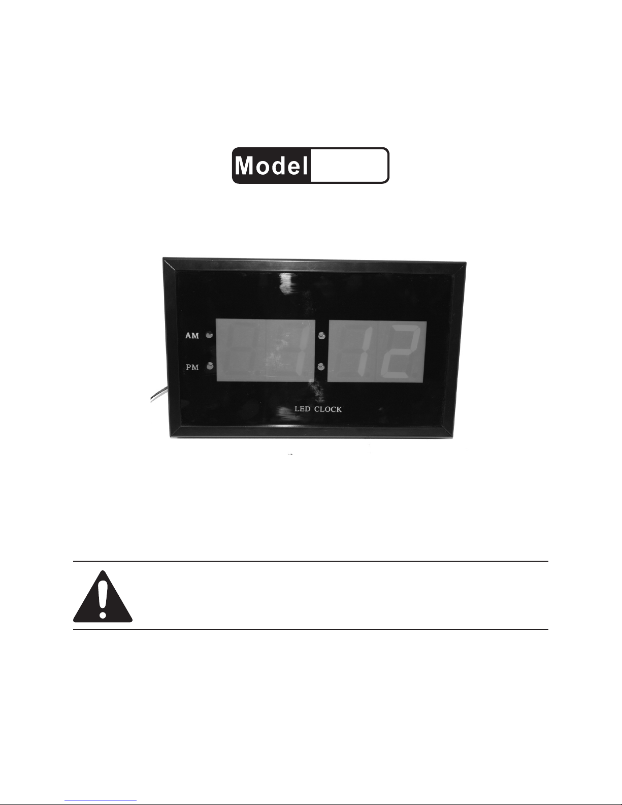
DIGITAL LED WALL CLOCK
98279
SET UP AND OPERATING INSTRUCTIONS
Distributed exclusively by Harbor Freight Tools®.
3491 Mission Oaks Blvd., Camarillo, CA 93011
Visit our website at: http://www.harborfreight.com
Read this material before using this product.
Failure to do so can result in serious injury.
SAVE THIS MANUAL.
Copyright© 2008 by Harbor Freight Tools®. All rights reserved. No portion of this manual or any artwork
contained herein may be reproduced in any shape or form without the express written consent of
Harbor Freight Tools. Diagrams within this manual may not be drawn proportionally. Due to continuing
improvements, actual product may differ slightly from the product described herein. Tools required for
assembly and service may not be included.
For technical questions or replacement parts, please call 1-800-444-3353.
Page 2
SAVE THIS MANUAL
Keep this manual for the safety warnings and precautions, assembly, operating, inspection, maintenance and cleaning
procedures. Write the product’s serial
number in the back of the manual near the
assembly diagram (or month and year of
purchase if product has no number). Keep
this manual and the receipt in a safe and
dry place for future reference.
IMPORTANT SAFETY
INFORMATION
In this manual, on the labeling,
and all other information provided with this product:
This is the safety alert
symbol. It is used to alert
you to potential personal
injury hazards. Obey all
safety messages that
follow this symbol to avoid
possible injury or death.
DANGER indicates
a hazardous
situation which, if not
avoided, will result in death or
serious injury.
WARNING
indicates a
hazardous situation which, if
not avoided, could result in
death or serious injury.
CAUTION, used
with the safety
alert symbol, indicates a
hazardous situation which, if
not avoided, could result in
minor or moderate injury.
NOTICE is used to
address practices
not related to personal injury.
CAUTION, without
the safety alert
symbol, is used to address
practices not related to
personal injury.
General Safety Warnings
WARNING! Read all safety
warnings and instructions.
Failure to follow the warnings and
instructions may result in electric
shock, re and/or serious injury.
Save all warnings and
instructions for future reference.
Electrical safety1.
Electrical products must match a.
the outlet. Never modify the plug
in any way. Unmodied plugs and
matching outlets will reduce risk of
electric shock.
Do not use any other adapter with b.
this Wall Clock. Use only the adapt-
er that is included. Use of a different
adapter could lead to product failure
and/or possible injury.
Avoid body contact with grounded c.
surfaces such as pipes, radiators,
ranges and refrigerators. There is
an increased risk of electric shock if
your body is grounded.
Do not use the Wall Clock out-d.
doors.
Do not expose Wall Clock to rain e.
or wet conditions. Water enter-
ing the Clock will increase the risk of
electric shock.
SKU 98279 For technical questions, please call 1-800-444-3353. Page 2
Page 3

2. Adapter use and care
a. Do not abuse Adapter or power
cord. Never use the cord for carry-
ing, pulling or unplugging the Wall
Clock.
b. Keep cord away from heat, oil,
sharp edges or moving parts.
Damaged or entangled cords in-
crease the risk of electric shock.
3. Personal safety
Stay alert, watch what you are a.
doing and use common sense
when operating this product. Do
not mount or set up the Wall Clock
while you are tired or under the inu ence of drugs, alcohol or medication.
b. Use indoors only.
c. Disconnect plug from the power
source before making any
adjustments, storing or changing
accessories.
d. Use for intended purposes only.
e. When mounting the Wall Clock,
check the drilling path for hidden
wires, cables and lines.
Interrupter (GFCI) should also be
implemented – it prevents sustained
electrical shock.
4. WARNING: Handling the cord on
this product will expose you to lead,
a chemical known to the State of
California to cause cancer, and birth
defects or other reproductive harm.
Wash hands after handling. (California Health & Safety Code § 25249.5,
et seq.)
5. The warnings, precautions, and
instructions discussed in this instruction manual cannot cover all
possible conditions and situations
that may occur. It must be under-
stood by the operator that common
sense and caution are factors which
cannot be built into this product, but
must be supplied by the operator.
SAVE THESE
INSTRUCTIONS.
f. This Wall Clock is not a toy. Keep
it out of reach of children.
g. People with pacemakers should
consult their physician(s) before
use. Electromagnetic elds in close
proximity to heart pacemaker could
cause pacemaker interference or
pacemaker failure. In addition,
people with pacemakers should:
• Avoid operating alone.
• Do not use with power switch
locked on.
• Properly maintain and inspect to
avoid electrical shock.
• Any power cord must be properly
grounded. Ground Fault Circuit
SKU 98279 For technical questions, please call 1-800-444-3353. Page 3
Page 4

GROUNDING
TO PREVENT
ELECTRIC SHOCK
AND DEATH FROM
INCORRECT GROUNDING
WIRE CONNECTION:
Check with a qualied
electrician if you are in doubt
as to whether the outlet is
properly grounded. Do not
modify the power cord plug
provided with the tool. Never
remove the grounding prong
from the plug. Do not use the
tool if the power cord or plug
is damaged. If damaged, have
it repaired by a service facility
before use. If the plug will not
t the outlet, have a proper
outlet installed by a qualied
electrician.
of electric shock. (See 3-Prong Plug
and Outlet.)
The grounding prong in the plug is 2.
connected through the green wire inside the cord to the grounding system
in the tool. The green wire in the cord
must be the only wire connected to
the tool’s grounding system and must
never be attached to an electrically
“live” terminal. (See 3-Prong Plug
and Outlet.)
The tool must be plugged into an 3.
appropriate outlet, properly installed
and grounded in accordance with all
codes and ordinances. The plug and
outlet should look like those in the
preceding illustration. (See 3-Prong
Plug and Outlet.)
Double Insulated Tools: Tools
with Two Prong Plugs
Grounded Tools: Tools with Three
Prong Plugs
Tools marked with “Grounding Re-1.
quired” have a three wire cord and
three prong grounding plug. The
plug must be connected to a properly
grounded outlet. If the tool should
electrically malfunction or break
down, grounding provides a low
resistance path to carry electricity
away from the user, reducing the risk
The Digital LED Wall Clock has a two-
prong plug.
Tools marked “Double Insulated” do 1.
not require grounding. They have
a special double insulation system
which satises OSHA requirements
and complies with the applicable
standards of Underwriters Laboratories, Inc., the Canadian Standard
Association, and the National Electri-
SKU 98279 For technical questions, please call 1-800-444-3353. Page 4
Page 5

cal Code. (See Outlets for 2-Prong
Plug.)
Double insulated tools may be used 2.
in either of the 120 volt outlets shown
in the preceding illustration. (See
Outlets for 2-Prong Plug.)
Extension Cords
Make sure the extension cord is prop-7.
erly wired and in good electrical condition. Always replace a damaged
extension cord or have it repaired by
a qualied electrician before using it.
Protect the extension cords from 8.
sharp objects, excessive heat, and
damp or wet areas.
Grounded1. tools require a three wire
extension cord. Double Insulated
tools can use either a two or three
wire extension cord.
As the distance from the supply outlet 2.
increases, you must use a heavier
gauge extension cord. Using extension cords with inadequately sized
wire causes a serious drop in voltage,
resulting in loss of power and possible tool damage.
(See Table A.)
The smaller the gauge number of the 3.
wire, the greater the capacity of the
cord. For example, a 14 gauge cord
can carry a higher current than a 16
gauge cord. (See Table A.)
When using more than one exten-4.
sion cord to make up the total length,
make sure each cord contains at
least the minimum wire size required.
(See Table A.)
RECOMMENDED MINIMUM WIRE
GAUGE FOR EXTENSION CORDS*
(120/240 VOLT)
EXTENSION CORD
NAMEPLATE
LENGTH
AMPERES
(at full load)
0 – 2.0 18 18 18 18 16
2.1 – 3.4 18 18 18 16 14
3.5 – 5.0 18 18 16 14 12
5.1 – 7.0 18 16 14 12 12
7.1 – 12.0 18 14 12 10 -
12.1 – 16.0 14 12 10 - -
16.1 – 20.0 12 10 - - -
TABLE A
25’
50’
75’
100’
* Based on limiting the line
voltage drop to ve volts at
150% of the rated amperes.
Symbology
Double Insulated
Canadian Standards Association
150’
If you are using one extension cord 5.
for more than one tool, add the
nameplate amperes and use the sum
to determine the required minimum
cord size. (See Table A.)
If you are using an extension cord 6.
outdoors, make sure it is marked with
the sufx “W-A” (“W” in Canada) to
indicate it is acceptable for outdoor
use.
SKU 98279 For technical questions, please call 1-800-444-3353. Page 5
V~
A
n0 xxxx/min.
Underwriters Laboratories, Inc.
Volts Alternating Current
Amperes
No Load Revolutions per Minute
(RPM)
Page 6

SPECIFICATIONS
Functions-Setting the Wall Clock
AC Adapter
Data Saving Device
Mode 12/24 Hour
Battery Type 3V Lithium, CR2032
Dimensions
120 VAC, 60 Hz,
Output: 9 VAC, 300 mA
Auto reset after power
loss
12-1/4” L x 7-5/8” H x
1-1/2” Deep
UNPACKING
When unpacking, check to make sure
that the item is intact and undamaged. If
any parts are missing or broken, please
call Harbor Freight Tools at the number
shown on the cover of this manual as soon
as possible.
INSTRUCTIONS FOR
Figure 1
Nail hole
Buttons:
A-B-C
Adapter
Plug
1. On the back of the Wall Clock are
three (3) buttons: A, B, and C. See
Figure 1, above. Each of these buttons is used to adjust the Wall Clock
settings:
A: Press “A” to scroll through and set
the Mode; Time, Hours/Minutes and
12 or 24 hour cycle.
PUTTING INTO USE
Read the ENTIRE IMPORTANT
SAFETY INFORMATION
section at the beginning of this
manual including all text under
subheadings therein before set
up or use of this product.
B: Press “B” to adjust the hour and
minute within each mode. Holding
down “B” will also change the Wall
Clock mode from a 12 hour clock to a
24 hour clock (military time).
C: Press “C” to toggle between Hours
and Minutes.
Hanging the Wall Clock
The Wall Clock has a hole in the 1.
back which can be used to mount the
Clock onto a hook, nail or anchor (not
included) on a wall.
Using the Adapter
Plug the Adapter into a 120 V electri-1.
cal outlet.
Plug the Adapter into the back of the 2.
Wall Clock, as shown in Figure 1.
SKU 98279 For technical questions, please call 1-800-444-3353. Page 6
Page 7

Changing the Battery
CLEANING AND
Make certain when changing the bat-1.
tery to replace with a battery of the
same type.
Set the Wall Clock over a surface that 2.
will allow you to recover any dropped
screws.
Remove the back from the Wall Clock 3.
by unscrewing each of the twelve
screws.
Figure 2
3V Lithium
Battery Holder
Battery,
CR2032
4. Remove backing from Wall Clock.
Slide battery out from battery holder
with the end of a at screwdriver (not
included.) Replace with new 3V,
CR2032 battery. Replace back cover
and thread in twelve screws.
WARNING!5. Do not modify or make
adjustments any other electrical components.
Any other maintenance beside 6.
changing of the battery should be
done by a qualied service technician.
MAINTENANCE
Clean the outside of the Wall Clock 1.
with a soft, dry cloth as necessary.
Do not use harsh abrasives or materials to clean the Wall Clock as these
will damage both the nish and LED
readout.
Replace the Battery every 6 months 2.
or when necessary. See section on
Changing the Battery on this page.
PLEASE READ THE FOLLOWING CAREFULLY
THE MANUFACTURER AND/OR DISTRIBUTOR
HAS PROVIDED THE PARTS LIST AND
ASSEMBLY DIAGRAM IN THIS MANUAL AS
A REFERENCE TOOL ONLY. NEITHER THE
MANUFACTURER OR DISTRIBUTOR MAKES
ANY REPRESENTATION OR WARRANTY OF
ANY KIND TO THE BUYER THAT HE OR SHE
IS QUALIFIED TO MAKE ANY REPAIRS TO THE
PRODUCT, OR THAT HE OR SHE IS QUALIFIED
TO REPLACE ANY PARTS OF THE PRODUCT.
IN FACT, THE MANUFACTURER AND/OR
DISTRIBUTOR EXPRESSLY STATES THAT
ALL REPAIRS AND PARTS REPLACEMENTS
SHOULD BE UNDERTAKEN BY CERTIFIED
AND LICENSED TECHNICIANS, AND NOT BY
THE BUYER. THE BUYER ASSUMES ALL RISK
AND LIABILITY ARISING OUT OF HIS OR HER
REPAIRS TO THE ORIGINAL PRODUCT OR
REPLACEMENT PARTS THERETO, OR ARISING
OUT OF HIS OR HER INSTALLATION OF
REPLACEMENT PARTS THERETO.
Record Product’s Serial Number Here:
Note: If product has no serial number,
record month and year of purchase
instead.
SKU 98279 For technical questions, please call 1-800-444-3353. Page 7
 Loading...