

Page 1
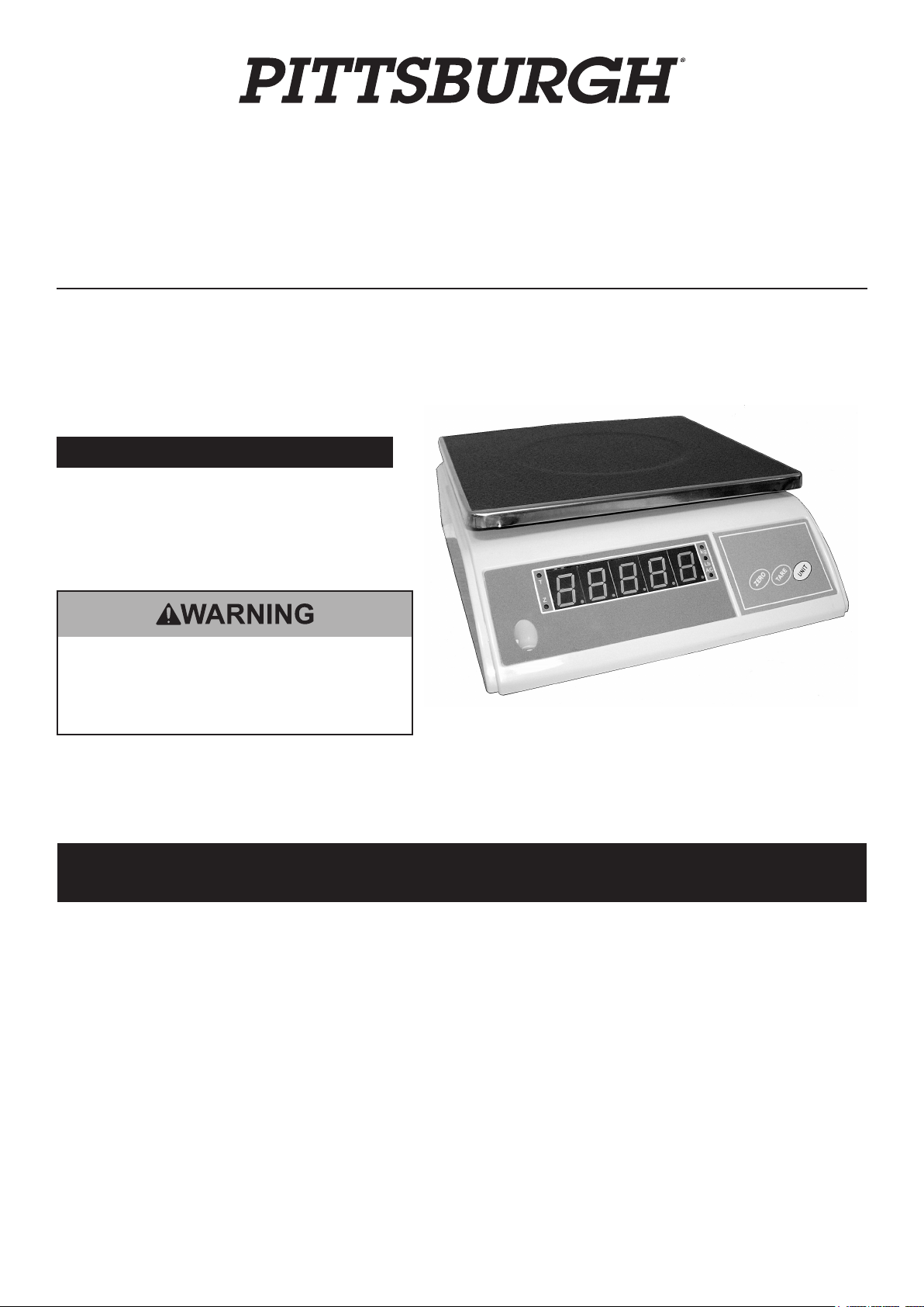
Bench Top Digital Scale
Item 98059 - 33 LB. Weight Capacity
Read this material before using this product.
Failure to do so can result in serious injury.
SAVE THIS MANUAL.
Not legal for trade or postage.
When unpacking, make sure that the product is intact and undamaged.
If any parts are missing or broken, please call 1-800-444-3353 as soon as possible.
Visit our website at: http://www.harborfreight.com
Copyright© 2008 by Harbor Freight Tools®. All rights reserved. No portion of this manual or any artwork contained herein may be reproduced in any shape
or form without the express written consent of Harbor Freight Tools. Diagrams within this manual may not be drawn proportionally. Due to continuing
improvements, actual product may differ slightly from the product described herein. Tools required for assembly and service may not be included.
Manual Revised 11d
Page 2

Specications
Input: 120 VAC~ / 60 Hz
Output: 9 VDC @ 500mA
Electrical
Requirements
Maximum
Weight
Capacity
Minimum
Weight
Control
Panel Button
Indicators
Red LED
Indicators
Additional
Features
Battery Type: 6V4ah/20HR
Battery Charge Time: 8 ~ 10 Hours
Adapter Plug: 2 Prong, Grounded
Power Switch: ON/Off Rocker Switch
33 Pounds (15 Kilograms)
7 ounces/200 grams
Yellow Push Button = Lb. or Kg.
Blue Push Button = Tare
Blue Push Button = Zero
T = Tare / Z = Zero
LB = Pound / KG = Kilogram
AC = AC Powered
Four Plastic Feet for Leveling of
Scale
This device complies with part 15 of the FCC
Rules. Operation is subject to the following
two conditions: (1) This device may not
cause harmful interference, and (2) this
device must accept any interference received, including
interference that may cause undesired operation.
CAUTION, used with the safety alert symbol,
indicates a hazardous situation which, if not
avoided, could result in minor or moderate injury.
NOTICE is used to address practices
not related to personal injury.
CAUTION, without the safety alert symbol, is used
to address practices not related to personal injury.
General Power Tool
Safety Warnings
WARNING Read all safety warnings and
instructions. Failure to follow the warnings and
instructions may result in electric shock, re and/
or serious injury.
Save all warnings and instructions for future
reference.
The term ″Scale″ in the warnings refers
to your battery-operated (cordless)
Bench Top Digital Scale.
Save This Manual
Keep this manual for the safety warnings
and precautions, assembly, operating, inspection,
maintenance and cleaning procedures. Write the
product’s serial number in the back of the manual near
the assembly diagram (or month and year of purchase
if product has no number). Keep this manual and the
receipt in a safe and dry place for future reference.
Important Safety Information
In this manual, on the labeling, and all other
information provided with this product:
This is the safety alert symbol. It is
used to alert you to potential
personal injury hazards. Obey all
safety messages that follow this
symbol to avoid possible injury or death.
DANGER indicates a hazardous situation which, if
not avoided, will result in death or serious injury.
WARNING indicates a hazardous situation which, if
not avoided, could result in death or serious injury.
1. Work area safety
a. Keep work area clean and well lit.
Cluttered or dark areas invite accidents.
b. Do not operate the Scale in explosive
atmospheres, such as in the presence
of ammable liquids, gases or dust.
Battery operated equipment create sparks
which may ignite the dust or fumes.
2. Electrical safety
a. The AC/DC Adapter plug must match the
outlet. Never modify the plug in any way. Do
not use any additional adapter plugs with
the Scale. Unmodied plugs and matching
outlets will reduce risk of electric shock.
b. Avoid body contact with grounded surfaces
such as pipes, radiators, ranges and
refrigerators. There is an increased risk of
electric shock if your body is grounded.
c. Do not expose the Scale to rain or wet
conditions. Water entering the Scale will
increase the risk of electric shock.
d. Do not abuse the AC/DC Adapter Cord.
Never use the Cord for carrying, pulling
or unplugging the AC/DC Adapter. Keep
the Cord away from heat, oil, sharp edges
or moving parts. Damaged or entangled
Cords increase the risk of electric shock.
e. When operating the Scale outdoors, use
an extension cord suitable for outdoor
Page 2SKU 98059 For technical questions, please call 1-800-444-3353.
Page 3

use. Use of a cord suitable for outdoor
use reduces the risk of electric shock.
f. If operating the Scale in a damp location
is unavoidable, use a Ground Fault Circuit
Interrupter (GFCI) protected supply. Use of
a GFCI reduces the risk of electric shock.
3. Personal safety
a. Stay alert, watch what you are doing and use
common sense when operating the Scale. Do
not use the Scale while you are tired or under
the inuence of drugs, alcohol or medication.
A moment of inattention while operating the
Scale may result in serious personal injury.
b. Use safety equipment. Always wear
eye protection. Safety equipment
such as ANSI-approved safety impact
goggles will reduce personal injuries.
c. Prevent unintentional starting. Ensure the
Power Switch (11) is in the off-position before
connecting to power source and/or battery
pack, picking up or carrying the tool. Carrying
battery operated equipment with your nger on
the Power Switch or energizing equipment that
have the Power Switch on invites accidents.
d. Do not overreach. Keep proper footing
and balance at all times. This enables better
control of the Scale in unexpected situations.
4. Scale use and care
a. Do not force the Scale. Use the correct
Scale for your application. The correct
Scale will do the job better and safer at
the rate for which it was designed.
b. Do not use the Scale if the Power Switch (11)
does not turn it on and off. Any equipment
that cannot be controlled with the Power
Switch is dangerous and must be repaired.
c. Disconnect the AC/DC Adapter Cord
before making any adjustments, changing
accessories, or storing the Scale. Such
preventive safety measures reduce the risk
of starting the equipment accidentally.
d. Store idle battery powered equipment
out of the reach of children and do not
allow persons unfamiliar with the Scale
or these instructions to operate the
equipment. Battery powered equipment are
dangerous in the hands of untrained users.
e. Maintain the Scale. Check for misalignment or
binding of moving parts, breakage of parts and
any other condition that may affect the Scale’s
operation. If damaged, have the Scale repaired
before use. Many accidents are caused by poorly
maintained battery operated power equipment.
f. Use the Scale in accordance with these
instructions, taking into account the working
conditions and the work to be performed. Use
of the Scale for operations different from those
intended could result in a hazardous situation.
5. Battery tool use and care
a. Recharge only with the AC/DC Adapter (25)
specied by the manufacturer. An Adapter that
is suitable for one type of Battery may create a
risk of re when used with another Battery Pack.
b. Use this Scale only with specically
designated Batteries. Use of any other
Battery may create a risk of injury and re.
c. When the Battery (21) is not in use, keep it
away from other metal objects, like paper clips,
coins, keys, nails, screws or other small metal
objects, that can make a connection from
one terminal to another. Shorting the Battery
Terminals together may cause burns or a re.
d. Under abusive conditions, liquid may be
ejected from the Battery (21). If contact with
liquid from the battery accidentally occurs,
ush with water. If liquid contacts eyes,
additionally seek medical help. Liquid ejected
from the Battery may cause irritation or burns.
6. Service
a. Have your Scale serviced by a qualied
repair person using only identical
replacement parts. This will ensure that
the safety of the equipment is maintained.
Specic Safety Warnings
1. Maintain labels and nameplates on the tool.
These carry important safety information. If
unreadable or missing, contact Harbor
Freight Tools for a replacement.
2. This Scale contains a sealed lead Battery. Do not
dispose of an old Battery in re to avoid explosion
and possible personal injury. Recycle old batteries
according to local solid waste authority procedures.
3. Do not exceed the Scale’s maximum
weight capacity of 33 pounds.
4. Avoid unintentional starting. Prepare to
begin work before turning on the Scale.
5. Do not leave the Scale unattended when it’s AC/
DC Adapter is plugged into an electrical outlet.
Turn off the equipment, and unplug the AC/DC
Adapter from its electrical outlet before leaving.
6. The AC/DC Adapter gets hot during
use. The Adapter’s heat can build up
to unsafe levels and create a re
hazard if it does not receive adequate
ventilation, due to an electrical fault,
or if it is used in a hot environment.
Do not place the Adapter on a ammable surface.
Especially avoid placing the Adapter on carpets
and rugs; they are not only ammable, but they
Page 3SKU 98059 For technical questions, please call 1-800-444-3353.
Page 4
also obstruct air ow under the Adapter. Place
the Adapter on a stable, solid, nonammable
surface (such as a stable metal workbench or
concrete oor) at least 1 foot away from all
ammable objects, such as drapes or walls. Keep
a re extinguisher and a smoke detector in the
area. Frequently monitor the Adapter and Battery
during use.
7. This product is not a toy. Keep it
out of reach of children.
8. People with pacemakers should consult their
physician(s) before use. Electromagnetic elds in
close proximity to heart pacemaker could cause
pacemaker interference or pacemaker failure. In
addition, people with pacemakers should:
• Avoid operating alone.
• Properly maintain and inspect to avoid electrical
shock.
• Any power cord must be properly
grounded. Ground Fault Circuit Interrupter
(GFCI) should also be implemented – it
prevents sustained electrical shock.
Grounding
TO PREVENT ELECTRIC
SHOCK AND DEATH FROM
INCORRECT GROUNDING
WIRE CONNECTION:
Check with a qualied electrician if you
are in doubt as to whether the outlet is
properly grounded. Do not modify the
Adapter Cord Plug provided with the tool.
Never remove the grounding prong from
the Plug. Do not use the Adapter if the
Cord or Plug is damaged. If damaged,
have it repaired by a service facility before
use. If the Plug will not t the outlet, have
a proper outlet installed by a qualied
electrician.
Double Insulated Tools: Tools
with Two Prong Plugs
9. The warnings, precautions, and instructions
discussed in this instruction manual cannot
cover all possible conditions and situations
that may occur. It must be understood by the
operator that common sense and caution are
factors which cannot be built into this product,
but must be supplied by the operator.
SAVE THESE
INSTRUCTIONS.
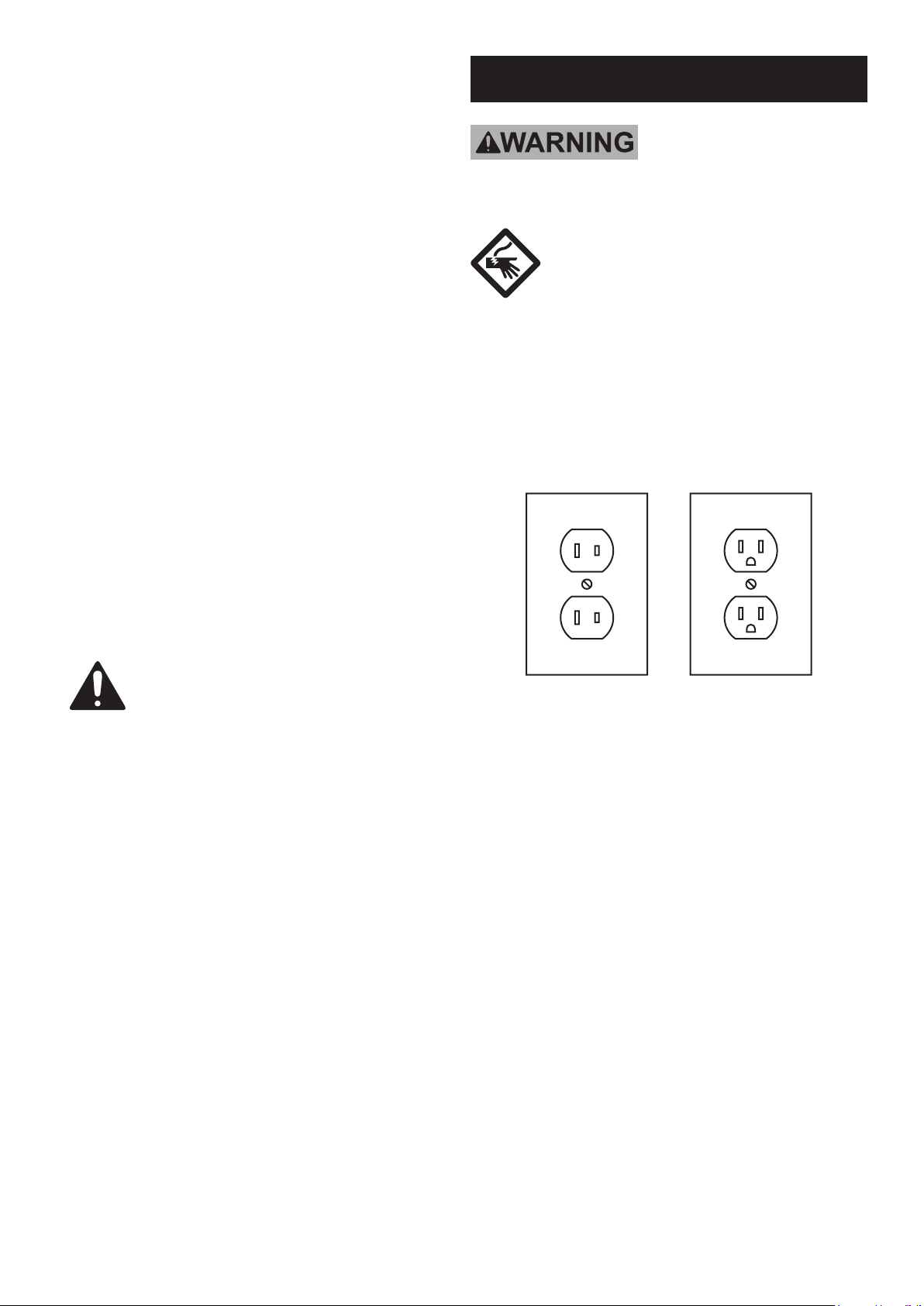
Outlets for 2-Prong Plug
1.
Tools marked “Double Insulated” do not require
grounding. They have a special double insulation
system which satises OSHA requirements
and complies with the applicable standards of
Underwriters Laboratories, Inc., the Canadian
Standard Association, and the National Electrical
Code.
(See Outlets for 2-Prong Plug.)
2. Double insulated tools may be used in either of the
120 volt outlets shown in the preceding illustration.
(See Outlets for 2-Prong Plug.)
Extension Cords
1. Grounded tools require a three wire extension
cord. Double Insulated tools can use
either a two or three wire extension cord.
2. As the distance from the supply outlet increases,
you must use a heavier gauge extension cord.
Using extension cords with inadequately sized wire
causes a serious drop in voltage, resulting in loss
of power and possible tool damage.
The smaller the gauge number of the wire, the
greater the capacity of the cord. For example,
a 14 gauge cord can carry a higher current
than a 16 gauge cord. (See Table A.)
Page 4SKU 98059 For technical questions, please call 1-800-444-3353.
Page 5

3. When using more than one extension cord
to make up the total length, make sure
each cord contains at least the minimum
wire size required. (See Table A.)
4. If you are using one extension cord for more
than one tool, add the nameplate amperes
and use the sum to determine the required
minimum cord size. (See Table A.)
5. If you are using an extension cord outdoors, make
sure it is marked with the sufx “W-A” (“W” in
Canada) to indicate it is acceptable for outdoor use.
6. Make sure the extension cord is properly wired
and in good electrical condition. Always replace
a damaged extension cord or have it repaired
by a qualied electrician before using it.
7. Protect the extension cords from sharp objects,
excessive heat, and damp or wet areas.
RECOMMENDED MINIMUM WIRE
GAUGE FOR EXTENSION CORDS*
(120/240 VOLT)
EXTENSION CORD
NAMEPLATE
LENGTH
AMPERES
(at full load)
0 – 2.0 18 18 18 18 16
2.1 – 3.4 18 18 18 16 14
3.5 – 5.0 18 18 16 14 12
5.1 – 7.0 18 16 14 12 12
7.1 – 12.0 18 14 12 10 -
12.1 – 16.0 14 12 10 - -
16.1 – 20.0 12 10 - - -
TABLE A
25’
50’
75’
100’
* Based on limiting the line
voltage drop to ve volts at
150% of the rated amperes.
150’
Symbology
Double Insulated
Canadian Standards Association
Underwriters Laboratories, Inc.
V~
A
n0 xxxx/min.
Volts Alternating Current
Amperes
No Load Revolutions per Minute
(RPM)
Page 5SKU 98059 For technical questions, please call 1-800-444-3353.
Page 6

Operating Instructions
Read the ENTIRE IMPORTANT SAFETY
INFORMATION section at the beginning of
this manual including all text under
subheadings therein before set up or use
of this product.
TO PREVENT SERIOUS
INJURY FROM ACCIDENTAL
OPERATION:
Turn off and unplug the unit before
performing any inspection, maintenance,
or cleaning procedures.
Scale Set Up
1. Always place the Scale on a clean, dry, at, level
workbench capable of supporting the weight
of the Scale and all objects to be weighed.
Charging the Battery
FIGURE A
(BOTTOM VIEW)
AC/DC ADAPTER CORD
(25)
CHARGING INPUT PORT
POWER SWITCH
(11)
2. The workbench area must be free of
vibration, strong air currents, direct
sunshine, and high temperatures.
3. To level the scale before use:
d. Turn the scale upside down.
e. Rotate the Leveling Feet (15) clockwise until they
are fully recessed. Then turn counterclockwise
three full turns. Hold each foot and rotate the
locking nut two full clockwise turns or until
the locking nut is not tightened on the foot.
f. Turn the scale right side up and place on the
work surface. Use the built-in leveling bubble
at the front left hand side of the Scale to check
if the scale is level. Rotate the feet individually
until the leveling bubble is centered.
g. When the scale is level, secure each foot in place
by turning its locking nut counterclockwise until
tight. Re-check the level, and re-adjust the feet if
necessary. The scale is now set for operation.
8. Check that the Scale’s Platform (1) will
not come in contact with any object before
or during the weighing process.
LEVELING FOOT
(15)
1.
To charge the Battery (21) of the Scale, insert
the AC/DC Adapter (25) Cord into the Charging
Input Port located on the underside of the
Scale. Make sure the Power Switch (11) is
in its “OFF” position throughout the charging
process. Plug the AC/DC Adapter into the
nearest 120 volt, grounded, electrical outlet.
IMPORTANT: The charge time for the Battery is 8 to 10
hours. Do not overcharge the Battery to avoid
damage to the Battery and/or AC/DC Adapter.
When nished charging, unplug the AC/DC Adapter
from its electrical outlet. Then unplug the Cord
from the Charging Input Port of the unit.
9. Route the AC/DC Adapter (25) Cord along
a safe route to reach the workbench
area without creating a tripping hazard or
exposing the Cord to possible damage.
Page 6SKU 98059 For technical questions, please call 1-800-444-3353.
Page 7

Operating the Scale
Components and Controls
FIGURE B
TARE
KILOGRAMS
Change Units of Measure
1. Press the “UNIT” button to switch between
the measurement unit settings. The Kg
(Kilogram) and LB (Pound) indicator lights
are located to the right of the Weight
Window, indicate which setting is current.
ZERO
PLATFORM (1)
“ZERO”
SCALE LEVEL
(26)
WEIGHT WINDOW
Refer to the above photos for the following
instructions. The function buttons (Tare,
Unit and Zero) are on the right side of the
front of the Scale. The indicator lights on
either side of the Weight Window display
information about the Scale’s settings.
AC POWER
”UNIT”
“TARE”
POUNDS
Set Container to Zero before Weighing
The Tare button is used to reset the scale to
zero when an empty container is set on the
scale, and the container is not included in
the weight of the objects to be weighed.
1. The “TARE” Indicator Light is located at the
top/left of the Weight Window (See Figure B).
Once the Scale is turned on, it will illuminate
to indicate the TARE weight is cleared.
2. To weigh objects in a container, but not include
the container weight, place an empty container on
the Platform (1) of the Scale. Press the “TARE”
button and wait for the Weight Window to display
“0.000”, indicating the Scale is ready for weighing.
Place the objects into the container, and the Weight
Window will display the weight of the objects.
Turning off the Scale
1. To turn off the Scale, simply turn the Power
Switch (11) to its “OFF” position.
2. Always make sure to store the Scale in
a clean, dry, safe location out of reach of
children and other unauthorized persons.
Note: Disconnect charger. Do not store the
scale with anything on top of it.
Turning on the Scale
Turn the Power Switch (11) to its “ON” position.
The Scale will do a self-check, during which
you can determine whether the Weight Window
and Zero functions are working normally.
Reset Weight to Zero
1. The “ZERO” Indicator Light is located at the
bottom/left of the Weight Window (See Figure
B). Once the Scale is turned on, it will illuminate
to indicate the Scale is at the ZERO position.
2. If the Weight Window does not display
“0.000” before you weigh an object, and
the zero range is less than 60g, press
the “ZERO” key. Begin weighing when
the Weight Window displays “0.000”.
Page 7SKU 98059 For technical questions, please call 1-800-444-3353.
Page 8

Maintenance and Servicing
Procedures not specically explained in this manual must
be performed only by a qualied technician.
TO PREVENT SERIOUS INJURY FROM ACCIDENTAL OPERATION:
Turn the Power Switch of the Scale to its “OFF” position and unplug the unit’s AC/DC
Adapter from its electrical outlet before performing any inspection, maintenance, or
cleaning procedures.
TO PREVENT SERIOUS INJURY FROM EQUIPMENT FAILURE:
Do not use damaged equipment. If abnormal noise or erratic values
are shown, have the problem corrected before further use.
Inspection, Maintenance, and Cleaning
1. BEFORE EACH USE, inspect the general condition of the Scale.
2. BATTERY REPLACEMENT: A Battery that fails to accept a charge is an indication the Battery
should be replaced. To replace the Battery requires the use of a soldering tool and specic
soldering expertise. It is recommended that only a qualied service technician perform a Battery
replacement procedure. Note: Battery must be fully discharged prior to any soldering.
3. AFTER USE, clean all external surfaces of the Scale with a soft, clean
cloth. Do not use solvents. Do not immerse the Scale in liquid.
4. WARNING! If the Cord of the AC/DC Adapter is damaged, it must
be replaced only by a qualied service technician.
Page 8SKU 98059 For technical questions, please call 1-800-444-3353.
Page 9

Troubleshooting
DISPLAY MEANING ACTION TO BE TAKEN
-------------------------------
----
(Mid horizontal line)
-------------------------------
----
(Upper horizontal line)
Lower horizontal line
-------------------------------
----
LO
(Alarm sound)
OL
(Alarm sound)
NO
(Alarm sound)
A long period display. The ZERO position is
unstable.
The ZERO position is too high. Have a qualied service technician service Scale.
The ZERO position is too low. Have a qualied service technician service Scale.
Voltage is lower than 4.8 +/-- 0.1V Recharge or change Battery.
Overload.
Circuit integrator faulty. Have a qualied service technician service Scale.
Work area too windy or too damp. Move Scale to
a calm, dry work area.
Immediately remove object(s) being weighed. Do
not exceed 33 LB. maximum weight capacity.
PLEASE READ THE FOLLOWING CAREFULLY
THE MANUFACTURER AND/OR DISTRIBUTOR HAS PROVIDED THE PARTS LIST AND ASSEMBLY DIAGRAM IN
THIS MANUAL AS A REFERENCE TOOL ONLY. NEITHER THE MANUFACTURER OR DISTRIBUTOR MAKES ANY
REPRESENTATION OR WARRANTY OF ANY KIND TO THE BUYER THAT HE OR SHE IS QUALIFIED TO MAKE ANY
REPAIRS TO THE PRODUCT, OR THAT HE OR SHE IS QUALIFIED TO REPLACE ANY PARTS OF THE PRODUCT.
IN FACT, THE MANUFACTURER AND/OR DISTRIBUTOR EXPRESSLY STATES THAT ALL REPAIRS AND PARTS
REPLACEMENTS SHOULD BE UNDERTAKEN BY CERTIFIED AND LICENSED TECHNICIANS, AND NOT BY THE
BUYER. THE BUYER ASSUMES ALL RISK AND LIABILITY ARISING OUT OF HIS OR HER REPAIRS TO THE
ORIGINAL PRODUCT OR REPLACEMENT PARTS THERETO, OR ARISING OUT OF HIS OR HER INSTALLATION
OF REPLACEMENT PARTS THERETO.
Page 9SKU 98059 For technical questions, please call 1-800-444-3353.
Page 10

Parts List & Assembly Diagram
Part #
1
2
3
4
5
6
7
8
9
10
11
12
13
Description
Platform
Back Label
Top Housing
Bolt (M6 x 25)
Top Support
Sensor
Bottom Support
Bolt (M5 x 12)
Bottom Housing
Bolt (M4 x 18)
Power Switch
Fuse Holder
10W Adapter
Qty
1
1
1
2
1
1
1
4
1
4
1
1
1
1
Part #
14
15
16
17
18
19
20
21
22
23
24
25
Description
Bolt (M3 x 16)
Foot
Adjuster
Switch Label
Circuit Board
Bolt (M3 x 6)
Face Label
Battery
Battery Cover
Mike
Bolt (m8 x 30)
AC/DC Adapter
Qty
2
4
1
1
1
2
1
1
1
1
2
1
10
11
13
14
2 3
16
4
24
17
18
19
20
21
22
23
5
6
7
9
8
12
15
Record Product’s Serial Number Here:
Note: If product has no serial number, record month and year of purchase instead.
Note: Some parts are listed and shown for illustration purposes only, and
are not available individually as replacement parts.
Page 10SKU 98059 For technical questions, please call 1-800-444-3353.
Page 11

90 Day Warranty
Harbor Freight Tools Co. makes every effort to assure that its products meet high quality and
durability standards, and warrants to the original purchaser that this product is free from defects
in materials and workmanship for the period of 90 days from the date of purchase. This warranty
does not apply to damage due directly or indirectly, to misuse, abuse, negligence or accidents,
repairs or alterations outside our facilities, criminal activity, improper installation, normal wear
and tear, or to lack of maintenance. We shall in no event be liable for death, injuries to persons
or property, or for incidental, contingent, special or consequential damages arising from the use
of our product. Some states do not allow the exclusion or limitation of incidental or consequential
damages, so the above limitation of exclusion may not apply to you. THIS WARRANTY IS
EXPRESSLY IN LIEU OF ALL OTHER WARRANTIES, EXPRESS OR IMPLIED, INCLUDING THE
WARRANTIES OF MERCHANTABILITY AND FITNESS.
To take advantage of this warranty, the product or part must be returned to us with transportation
charges prepaid. Proof of purchase date and an explanation of the complaint must accompany the
merchandise. If our inspection veries the defect, we will either repair or replace the product at our
election or we may elect to refund the purchase price if we cannot readily and quickly provide you
with a replacement. We will return repaired products at our expense, but if we determine there is
no defect, or that the defect resulted from causes not within the scope of our warranty, then you
must bear the cost of returning the product.
This warranty gives you specic legal rights and you may also have other rights which vary from
state to state.
Page 11SKU 98059 For technical questions, please call 1-800-444-3353.
Page 12

3491 Mission Oaks Blvd. • PO Box 6009 • Camarillo, CA 93011 • (800) 444-3353
 Loading...