

Page 1
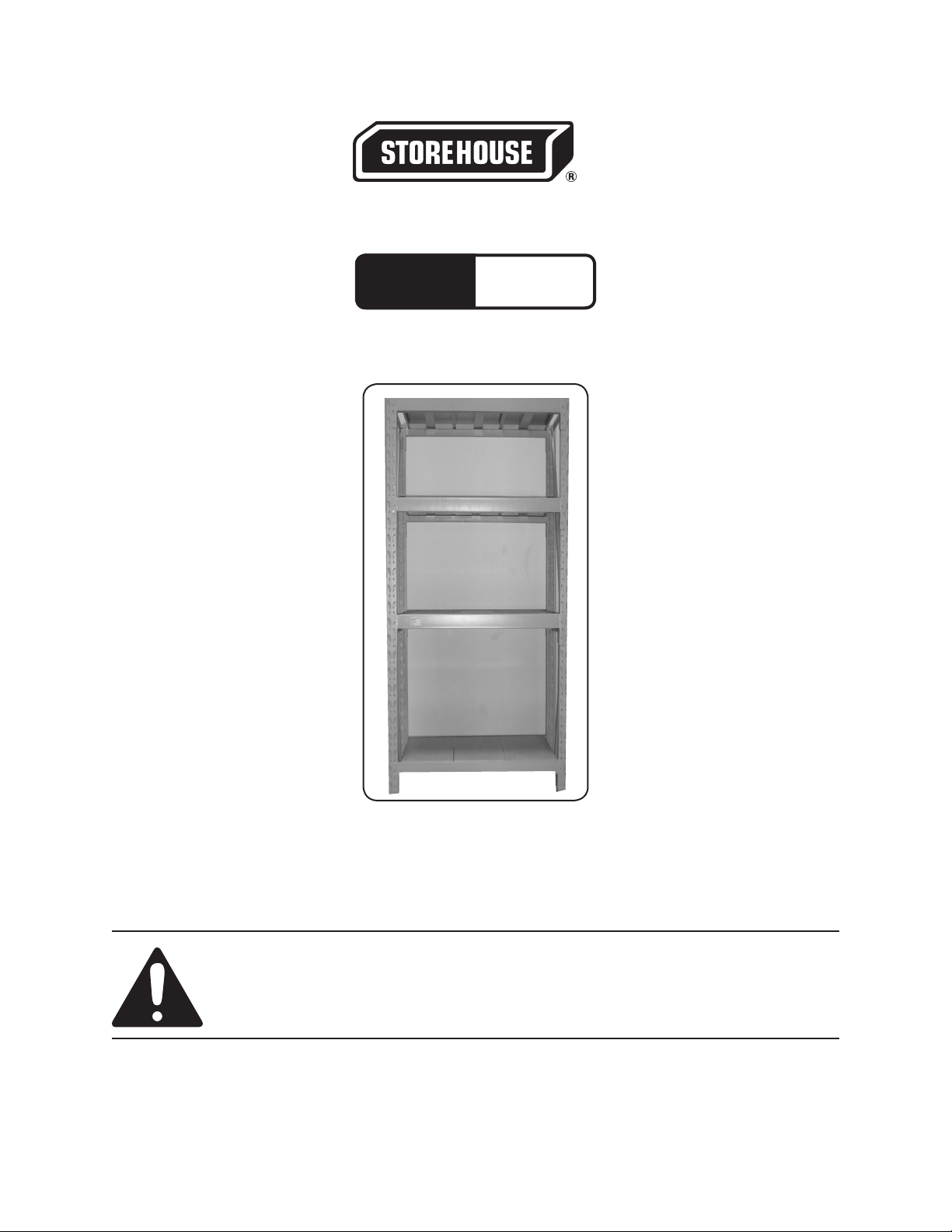
HEAVY DUTY STORAGE RACK
Model
97563
ASSEMBLY, OPERATING, AND MAINTENANCE
INSTRUCTIONS
Diagrams within this manual may not be drawn proportionally.
Due to continuing improvements, actual product may differ slightly from the product described herein.
Distributed exclusively by Harbor Freight Tools®.
3491 Mission Oaks Blvd., Camarillo, CA 93011
Visit our website at: http://www.harborfreight.com
Read this material before using this product.
Failure to do so can result in serious injury.
SAVE THIS MANUAL.
Copyright© 2007 by Harbor Freight Tools®. All rights reserved. No portion of this
manual or any artwork contained herein may be reproduced in any shape or form
without the express written consent of Harbor Freight Tools.
For technical questions or replacement parts, please call 1-800-444-3353.
Page 2
SAVE THIS MANUAL
Keep this manual for the safety warnings and precautions, assembly, operating,
inspection, maintenance and cleaning procedures. Write the product’s serial number
in the back of the manual near the assembly diagram (or month and year of purchase if
product has no number). Keep this manual and the receipt in a safe and dry place for
future reference.
IMPORTANT SAFETY INSTRUCTIONS
In this manual, on the labeling, and all other information
provided with this product:
This is the safety alert symbol. It is used to alert you to potential
personal injury hazards. Obey all safety messages that follow this
symbol to avoid possible injury or death.
DANGERDANGER
WARNINGWARNING
CAUTIONCAUTION
NoticeNotice
CAUTIONCAUTION
General and Specic Safety Warnings
DANGER indicates a hazardous situation
which, if not avoided, will result in death or
serious injury.
WARNING indicates a hazardous situation
which, if not avoided, could result in death
or serious injury.
CAUTION, used with the safety alert
symbol, indicates a hazardous situation
which, if not avoided, could result in minor
or moderate injury.
NOTICE is used to address practices not
related to personal injury.
CAUTION, without the safety alert symbol,
is used to address practices not related to
personal injury.
1.
2.
3.
Always wear ANSI-approved safety goggles and work gloves when assembling,
removing shelves, or changing location of shelving on this Heavy Duty Storage
Unit.
Always assemble this Storage Unit on a level surface.
Evenly distribute the weight of load on each shelf. Place heaviest items on the
bottom shelves.
Page 2SKU 97563 For technical questions, please call 1-800-444-3353.
Page 3

4.
Do not overload or exceed the maximum shelf capacity of 600 lb.
5.
6.
7.
8.
9.
Do not stand on, or use this Storage Unit as a ladder.
Should there be a need to change the level of a shelf, be sure to disassemble
and reassemble one shelf at a time following procedures in “Assembly” section
located on pages 5 and 6 of this manual.
Do not use this Storage Unit for other than intended use.
Maintain labels and nameplates on the appliance. These carry important safety
information. If unreadable or missing, contact Harbor Freight Tools for a replace-
ment.
The warnings, precautions, and instructions discussed in this instruction manual
cannot cover all possible conditions and situations that may occur. It must be
understood by the operator that common sense and caution are factors which
cannot be built into this product, but must be supplied by the operator.
SAVE THESE INSTRUCTIONS.
Page 3SKU 97563 For technical questions, please call 1-800-444-3353.
Page 4

SPECIFICATIONS
Upright Posts: Stamped and Formed 16 Gauge Steel - Q’ty 4
Construction Materials
Maximum Weight per
Shelf
Shelving Section
Dimensions
Side Sway Bars: Tubular Steel
L - Shaped Safety Pins and Other Hardware: Zinc Plated Steel
Shelves: Stamped and Formed Steel
600 lb
22-1/2” L X 13-7/8” W X 1-1/16” H - Q’ty 15
UNPACKING
When unpacking, check to make sure that the item is intact and undamaged. If
any parts are missing or broken, please call Harbor Freight Tools at the number shown
on the cover of this manual as soon as possible.
SET UP INSTRUCTIONS
Read the ENTIRE IMPORTANT SAFETY INSTRUCTIONS section at the
beginning of this manual including all text under subheadings therein
before set up or use of this product.
Note: For additional information regarding the parts listed in the following pages, refer
to the Assembly Diagram near the end of this manual.
Assembly.
1.
NOTE: Use two persons to assemble this Storage Rack. The Upright Posts
(2) are directional, the slots must face inward (see Figure 2 on page 5).
Long Rod (8)
Upright Post (2)
Nut (5)
Short Rod (3)
Long Rod (8)
Cross Beam (6)
Figure 1
2.
Assemble two of the Upright Posts (2) using three of the horizontal Short Rods
(3), and two of the Long Rods (8). Use six Bolts (1), twelve Flat Washers (4),
Page 4SKU 97563 For technical questions, please call 1-800-444-3353.
Page 5

one on each side, and six Nuts (5). Hand tighten the Nuts (5) initially (see Fig-
ures 1 and 2).
3.
Flat Washer
Nut
Bolt
Upright Post
Long Rod
Note:
Foot Plate at
Short Rod
base of uprights
must rest on the
oor.
Repeat step 1 to assemble the second Upright Post set.
Safety Pin
Figure 2
4.
5.
6.
7.
Using two persons, stand up the two Upright Post assemblies in position and at-
tach one Cross Beam (6) into the second Slot from the bottom of the two Upright
Posts. These Cross Beams (6) have two metal Tabs on each end which slip into
the Slots of the Upright Posts (2). Make sure the Flange on the Cross Beam (6)
is facing up. This Flange will hold the Steel Shelves (7) in place (See Figure 1).
Repeat step 4 with a Cross Beam (6) on opposite side of Upright Post assembly.
Only one person is needed to nish the assembly. Continue to attach Cross
Beams (6) (Flanges pointing upward) at desired heights. The Cross Beams (6)
on the top level must be positioned at the top Slot of the Upright Posts (2). Make
sure each Cross Beam (6) is located in same Slots as the Cross Beam directly
opposite its height on the Upright Post (2). This is to ensure that wneh the
shelves are inserted, they will lay at.
Use a rubber mallet (not supplied) to drive the Wedge at both edges of the Cross
Beams (6) into the Slots on the Upright Posts (2) as deep as possible. Strike the
Cross Beam (6) with the mallet as close to the Upright Post (2) as you can.
Page 5SKU 97563 For technical questions, please call 1-800-444-3353.
Page 6

Safety Pin (9)
Cross Beam (6)
Upright Post (2)
Figure 3
8.
9.
10.
1.
2.
Insert the Safety Pins (9) into Holes located in, and lined up with, both the Up-
right Posts (2) and Cross Beams (6). This is an important step and will keep the
Cross Beams from slipping up and coming loose (See Figure 3).
Lay the Steel Shelves (7) as needed into the Cross Beams (6). You can use up
to 15 Steel Shelves (7), three per level, or leave some out in order to make room
for taller items being stored.
Make sure all Steel Shelves are in correct and level positions. Tighten all Nuts
(5) and Bolts (1).
OPERATING INSTRUCTIONS
Read the ENTIRE IMPORTANT SAFETY INFORMATION section at the
beginning of this manual including all text under subheadings therein
before set up or use of this product.
This Heavy Duty Storage Rack may be used to store items of different widths and
heights by removing any of the 15 Steel (7) Shelves. Each Shelf will support up
to 600 lb.
If needed, the Cross Beams (6) holding each shelf may be raised or lowered us-
ing procedures found in the “Assembly” portion of this manual on pages 5 and 6.
Page 6SKU 97563 For technical questions, please call 1-800-444-3353.
Page 7

MAINTENANCE AND SERVICING
Any maintenance or service not specically explained in this manual must be
performed by a qualied service technician.
Cleaning and Maintenance
1.
Periodically inspect the general condition of this Storage Rack. Check for loose
screws, misalignment of parts, cracked or broken parts, and any other condition
that may affect its safe operation.
2.
Wipe down with clean, moist cloth periodically.
PLEASE READ THE FOLLOWING CAREFULLY
THE MANUFACTURER AND/OR DISTRIBUTOR HAS PROVIDED THE PARTS LIST AND ASSEMBLY
DIAGRAM IN THIS MANUAL AS A REFERENCE TOOL ONLY. NEITHER THE MANUFACTURER OR
DISTRIBUTOR MAKES ANY REPRESENTATION OR WARRANTY OF ANY KIND TO THE BUYER THAT
HE OR SHE IS QUALIFIED TO MAKE ANY REPAIRS TO THE PRODUCT, OR THAT HE OR SHE IS
QUALIFIED TO REPLACE ANY PARTS OF THE PRODUCT. IN FACT, THE MANUFACTURER AND/OR
DISTRIBUTOR EXPRESSLY STATES THAT ALL REPAIRS AND PARTS REPLACEMENTS SHOULD
BE UNDERTAKEN BY CERTIFIED AND LICENSED TECHNICIANS, AND NOT BY THE BUYER. THE
BUYER ASSUMES ALL RISK AND LIABILITY ARISING OUT OF HIS OR HER REPAIRS TO THE
ORIGINAL PRODUCT OR REPLACEMENT PARTS THERETO, OR ARISING OUT OF HIS OR HER
INSTALLATION OF REPLACEMENT PARTS THERETO.
PARTS LIST
Part Description Q’ty
1 Bolt 12
2 Upright Posts 4
3 Short Rods 6
4 Flat Washer 24
5 Nut 12
Part Description Q’ty
6 Cross Beam 10
7 Steel Shelf 15
8 Long Rods 4
9 Safety Pin 20
Record Product’s Serial Number Here:
Note: If product has no serial number, record month and year of purchase instead.
Note: Some parts are listed and shown for illustration purposes only, and are not avail-
able individually as replacement parts.
Page 7SKU 97563 For technical questions, please call 1-800-444-3353.
Page 8

ASSEMBLY DIAGRAM
Page 8SKU 97563 For technical questions, please call 1-800-444-3353.
 Loading...