

Page 1
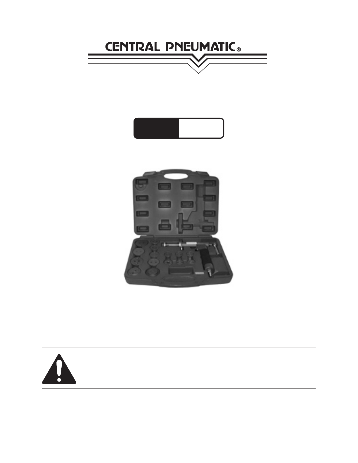
BRAKE CALIPER WIND BACK
Model
97456
TOOL SET
SET UP AND OPERATING INSTRUCTIONS
Diagrams within this manual may not be drawn proportionally.
Due to continuing improvements, actual product may differ slightly from the product described herein.
Distributed exclusively by Harbor Freight Tools®.
3491 Mission Oaks Blvd., Camarillo, CA 93011
Visit our website at: http://www.harborfreight.com
Read this material before using this product.
Failure to do so can result in serious injury.
SAVE THIS MANUAL.
Copyright© 2008 by Harbor Freight Tools®. All rights reserved. No portion of this
manual or any artwork contained herein may be reproduced in any shape or form
without the express written consent of Harbor Freight Tools.
For technical questions or replacement parts, please call 1-800-444-3353.
Page 2

SAVE THIS MANUAL
Keep this manual for the safety warnings and precautions, assembly, operating, inspection, maintenance and cleaning
procedures. Write the product’s serial
number in the back of the manual near the
assembly diagram (or month and year of
purchase if product has no number). Keep
this manual and the receipt in a safe and
dry place for future reference.
IMPORTANT SAFETY
INFORMATION
In this manual, on the labeling,
and all other information
provided with this product:
This is the safety alert
symbol. It is used to alert
you to potential personal
injury hazards. Obey all
safety messages that
follow this symbol to avoid
possible injury or death.
DANGER
WARNING
CAUTION
DANGER indicates
a hazardous
situation which, if not
avoided, will result in death or
serious injury.
WARNING
indicates a
hazardous situation which, if
not avoided, could result in
death or serious injury.
CAUTION, used
with the safety
alert symbol, indicates a
hazardous situation which, if
not avoided, could result in
minor or moderate injury.
Notice
CAUTION
NOTICE is used to
address practices
not related to personal injury.
CAUTION, without
the safety alert
symbol, is used to address
practices not related to
personal injury.
General Safety Rules
WARNING! Read all instructions
Failure to follow all instructions
listed below may result in
serious injury. The term
“pneumatic tool” in all of the
warnings listed below refers to
your Caliper Wind Brake Tool Set.
SAVE THESE INSTRUCTIONS
Work area safety1.
Keep work area clean and well a.
lit. Cluttered or dark areas invite
accidents.
Do not operate pneumatic tools in b.
explosive atmospheres, such as in
the presence of ammable liquids,
gases or dust. Pneumatic tools
create sparks which may ignite the
dust or fumes.
Keep children and bystanders away c.
while operating a pneumatic tool.
Distractions can cause you to lose
control.
Personal safety3.
Stay alert, watch what you are doing a.
and use common sense when operating a pneumatic tool. Do not use a
pneumatic tool while you are tired or
under the inuence of drugs, alcohol
or medication. A moment of inatten-
Page 2SKU 97456 For technical questions, please call 1-800-444-3353.
Page 3

tion while operating pneumatic tools
may result in serious personal injury.
be controlled with the Trigger is
dangerous and must be repaired.
Use safety equipment. Always b.
wear ANSI-approved safety impact
goggles and NIOSH-approved dust
mask/respirator. Safety equipment
such as non-skid safety shoes, hard
hat, or hearing protection used for
appropriate conditions will reduce
personal injuries.
Avoid accidental starting. Ensure c.
the Trigger (6A) is in the off-position
before connecting to an air supply.
Carrying pneumatic tools with your
nger on the Trigger or connecting
pneumatic tools that have the Trig-
ger on invites accidents.
Remove any adjusting key or wrench d.
before turning the pneumatic tool on.
A wrench or a key left attached to a
rotating part of the pneumatic tool
may result in personal injury.
Do not overreach. Keep proper foot-e.
ing and balance at all times. This
enables better control of the pneumatic tool in unexpected situations.
Dress properly. Do not wear loose f.
clothing or jewelry. Keep your hair,
clothing and gloves away from moving parts. Loose clothes, jewelry or
long hair can be caught in moving
parts.
Pneumatic tool use and care4.
Do not force the pneumatic tool. a.
Use the correct pneumatic tool
for your application. The correct
pneumatic tool will do the job better
and safer at the rate for which it was
designed.
Do not use the pneumatic tool if the b.
Trigger (6A) does not turn it on and
off. Any pneumatic tool that cannot
Disconnect the air hose from the c.
pneumatic tool and release any
remaining air pressure before
making any adjustments, changing
accessories, or storing pneumatic
tools. Such preventive safety
measures reduce the risk of starting
the pneumatic tool accidentally.
Store idle pneumatic tools out of the d.
reach of children and do not allow
people unfamiliar with the pneumatic
tool or these instructions to operate
the pneumatic tool. Pneumatic
tools are dangerous in the hands of
untrained users.
Maintain pneumatic tools. Check for e.
misalignment or binding of moving
parts, breakage of parts and any
other condition that may affect
the pneumatic tool’s operation. If
damaged, have the pneumatic
tool repaired before use. Many
accidents are caused by poorly
maintained pneumatic tools.
Use the pneumatic tool and its f.
accessories in accordance with
these instructions and in the
manner intended for the particular
type of pneumatic tool, taking into
account the working conditions and
the work to be performed. Use of
the pneumatic tool for operations
different from those intended could
result in a hazardous situation.
Service5.
Have your pneumatic tool serviced a.
by a qualied repair person using
only identical replacement parts.
This will ensure that the safety of the
pneumatic tool is maintained.
Page 3SKU 97456 For technical questions, please call 1-800-444-3353.
Page 4

Vibration Hazard
This tool vibrates during use.
Repeated or long-term exposure to
vibration may cause temporary or
permanent physical injury, particularly
to the hands, arms and shoulders. To
reduce the risk of vibration-related
injury:
Anyone using vibrating tools regularly 1.
or for an extended period should
rst be examined by a doctor and
then have regular medical checkups to ensure medical problems are
not being caused or worsened from
use. Pregnant women or people
who have impaired blood circulation
to the hand, past hand injuries,
nervous system disorders, diabetes,
or Raynaud’s Disease should not
use this tool. If you feel any medical
or physical symptoms related to
vibration (such as tingling, numbness,
and white or blue ngers), seek
medical advice as soon as possible.
Do not smoke during use. Nicotine 2.
reduces the blood supply to the
hands and ngers, increasing the risk
of vibration-related injury.
Wear suitable gloves to reduce the 3.
vibration effects on the user.
Use tools with the lowest vibration 4.
when there is a choice between
different processes.
Include vibration-free periods each 5.
day of work.
Grip tool as lightly as possible (while 6.
still keeping safe control of it). Let
the tool do the work.
abnormal vibration occurs, stop use
immediately.
Specic Safety Rules
Maintain labels and nameplates 1.
on the Caliper Wind Brake Tool
Set. These carry important safety
information. If unreadable or missing,
contact Harbor Freight Tools for a
replacement.
Use compressed air only. Use clean, 2.
dry, regulated, compressed air at 110
PSI. Do not exceed 110 PSI.
Avoid unintentional starting. Prepare 3.
to begin work before turning on the
tool.
Do not lay the tool down until it has 4.
come to a complete stop. Moving
parts can grab the surface and pull
the tool out of your control.
Do not leave the tool unattended 5.
when it is connected to a compressed
air supply. Turn off the tool, and
diconnect it from its compressed air
supply before leaving.
This product is not a toy. Keep it out 6.
of reach of children.
The warnings, precautions, and in-7.
structions discussed in this instruction
manual cannot cover all possible conditions and situations that may occur.
It must be understood by the operator
that common sense and caution are
factors which cannot be built into this
product, but must be supplied by the
operator.
SAVE THESE
To reduce vibration, maintain the tool 7.
as explained in this manual. If any
INSTRUCTIONS.
Page 4SKU 97456 For technical questions, please call 1-800-444-3353.
Page 5

SPECIFICATIONS
Product
Application
Operating Air
Pressure
Air Inlet Size 1/4” - 18 NPT
Fabrication
Additional
Features
Universal t. Works with most European,
Asian, and United States made vehicles.
72 PSI to 110 PSI
Forged steel Disc Adapters.
Die Cast Aluminum Gun with stamped
steel and machined steel.
Rotates left or right to wind back pistons.
Magnetic pad base.
Trigger pressure speed control.
15 Pads.
UNPACKING
WARNING
TO PREVENT
FROM ACCIDENTAL
OPERATION:
Disconnect the Caliper Wind
Brake Tool from its
compressed air supply
source, and release any
compressed air from the tool
before performing any set up
and operating procedures.
Product Features
SERIOUS INJURY
When unpacking, check to make sure
that the item is intact and undamaged. If
any parts are missing or broken, please
call Harbor Freight Tools at the number
shown on the cover of this manual as soon
as possible.
Note: For additional information regarding
the parts listed in the following pages,
refer to the Assembly Diagram near
the end of this manual.
OPERATING INSTRUCTIONS
Read the ENTIRE IMPORTANT
SAFETY INFORMATION section
at the beginning of this manual
including all text under
subheadings therein before set
up or use of this product.
Note: For additional information regarding
the parts listed in the following pages,
refer to the Assembly Diagram near
the end of this manual.
FIGURE A
SLIDING BAR
(2A)
PAD
AIR CONNECTOR (5A)
TRIGGER (6A)
Product Applications
The following indicates which specic 1.
Pad must be used for each vehicle
make and model.
(See Figure B, next page.)
Pad 2: Citroen/XM®, Xantia® (F/R)
Pad 3: Audi®(F), FIAT/Alpha Romeo®,
Ford Fiesta® (F), ISUZU® (F),
HONDA® Concesto (F),
Jaguar® XJ6, XJ40 (F/R),
BMW® 318is, 320i, 325TD,
DIRECTION
HANDLE
18A)
Page 5SKU 97456 For technical questions, please call 1-800-444-3353.
Page 6

518i, 525i, 1x, 740i, 850ci,
Sri (R), Toyota® Celica, Co-
M5 (F), Mercedes Benz® 190,
200, 300, 420, 560 (F),
Mitsubishi® Colt (F), Nissan
®
Mlera, Stanza, Sunny (F),
Range Rover® Austin, Metro,
200 & 400 Series, Maestra,
Montego (F), Toyota® Camry
(F), Volvo® (F), VW® Passat,
Golf, GTI (F).
Pad 4: Ford® AU & NZ, Telstar, Laser
(R),
Mazda® (R), Saab® 9000 (R),
Fiat/Alpha Romeo® 1642 (R),
Honda® Prelude, CRS, 16i,
GM® Saturn, Grand Prix,
Lumina (R).
3/8” Drive Adapter 5: Used with ex-
tension bar and ratchet (not
rolla, GT, MR2 (R), VW
Golf Gti, Jetta, Synchro,
Jetta Gti, Passat CL, GL,
GT, Corrado, Scirroca, GTX.
Pad 8: General Motors® most 1-7/8”
diameter pistons.
Pad 9: General Motors® most 2-1/8”
diameter pistons.
Pad O: General Motors® most 2-1/2”
diameter pistons, Cadillac,
Seville, & El Dorado 79.
Pad Z: Renault® R21, Laguna (R).
Pad M: Ford®, MINI/Cooper.
Pad N: SAAB®, Honda®.
Pad E: Nissan® Maxima.
Pad G: Opel® (R).
Pad K: Citroen®.
included) when applying
more strength to the piston.
Pad 6: Nissan® Primera, VW® Golf IV
Pad 7: Audi® 80, 90, V8 100, Coupe
E (R), Range Rover® 800
ABS, Subaru® L, Z (R), Ford
®
Sierra, Granada, Scorpio (R),
Nissan® Bluebird, Silvia
Turbo, Primera,
Peugeot® 405,
1.9Gi, Gri, Sri, Gtxi, MI, 2.0
7
O
E
9
K
2
6
45GZM
8
3
N
FIGURE B
Page 6SKU 97456 For technical questions, please call 1-800-444-3353.
Page 7

General Operating Instructions
Place the proper Pad on the Sliding 1.
Bar (2A) of the tool. (See Figure C.)
DIRECTION HANDLE (18A)
FIGURE C
SLIDING BAR (2A)
PAD
Connect an air hose to the Air 2.
Connector (5A) of the tool. Turn
on the air compressor, and set its
regulator between 72 and 110 PSI.
Do not exceed 110 PSI.
(See Assy. Diagram.)
Insert Adapter (14A) onto the caliper 3.
of the vehicle. Push Sliding Bar
(2A) forward, rotating the Direction
Handle (18A) to left or right in order
to engage the pin/pins on the face of
the Pad with the holes on llister of
the Caliper. (See Figure D.)
TRIGGER (6A)
FIGURE E
5. When nished, release pressure on
the Trigger (6A). Then pull out on the
Sliding Bar (2A) to remove the Pad
from the caliper. (See Figure F.)
Turn off the air compressor. 6.
Disconnect the air hose from the tool.
Squeeze the tool’s Trigger (6A) to
release any remaining compressed
air in the tool. Then store the tool in a
clean, dry, safe location out of reach
of children and other unauthorized
people.
PAD
HEX SET SCREW (17A)
SLIDING BAR
(2A)
PAD
FIGURE D
4. Squeezing the Trigger (6A) will force
Sliding Bar (2A) forward to expand
the Caliper. (See Figure E.)
SLIDING BAR (2A)
TRIGGER (6A)
FIGURE F
MAINTENANCE AND
SERVICING
Procedures not specically
explained in this manual
must be performed only by a
qualied technician.
REV 08c
Page 7SKU 97456 For technical questions, please call 1-800-444-3353.
Page 8

WARNING
TO PREVENT SERIOUS
INJURY FROM ACCIDENTAL
OPERATION:
Disconnect the tool from
its compressed air supply
source before performing any
inspection, maintenance, or
cleaning procedures.
TO PREVENT SERIOUS
INJURY FROM TOOL
FAILURE:
Do not use damaged
equipment. If abnormal noise
or vibration occurs, have
the problem corrected before
further use.
Cleaning, Maintenance, and
Lubrication
BEFORE EACH USE,1. inspect the
general condition of the tool. Check
for loose screws, misalignment or
binding of moving parts, cracked or
broken parts, and any other condition
that may affect its safe operation.
AFTER USE,2. clean external surfaces
of the tool with clean, moist cloth.
Then dry. Do not use solvents. Do
not immerse in liquid.
WHEN STORING, 3. Keep the tool
and its accessories in its Carrying
Case. Store the Carrying Case in a
clean, dry, safe location out of reach
of children and other unauthorized
people.
Page 8SKU 97456 For technical questions, please call 1-800-444-3353.
Page 9

Description
Body
Sliding Bar
Part #
1A
2A
O-Ring
Bottom Cap
3A
4A
PARTS LIST & ASSEMBLY DIAGRAM
Air Connector
Trigger
Hollow Pin
Spring
O-Ring
Air Control Pin
O-Ring
Base Nut
O-Ring
Adapter
Steel Ball
Spring
Hex Set Screw
Direction Handle
Rivet
Piston O-Ring
Piston
Bolt
O-Ring
O-Ring
5A
6A
7A
8A
9A
10A
11A
12A
13A
14A
15A
16A
17A
18A
19A
20A
21A
22A
23A
24A
31A
3A
30A
Top Base Bolt
Hollow Pin
Bottom Base
25A
26A
27A
Pin
28A
Magnet
Mesh Screen
29A
30A
Foam
31A
18A
19A
23A
22A
24A
17A
2A
21A
20A
16A
15A
13A
5A
1A
4A
6A
7A
8A
9A
10A
11A
12A
25A
26A
27A
28A
29A
14A
REV 08c
Page 9SKU 97456 For technical questions, please call 1-800-444-3353.
Page 10

LIMITED 1 YEAR WARRANTY
Harbor Freight Tools Co. makes every effort to assure that its products meet high
quality and durability standards, and warrants to the original purchaser that this product is
free from defects in materials and workmanship for the period of one year from the date
of purchase (90 days if used by a professional contractor or if used as rental equipment).
This warranty does not apply to damage due directly or indirectly, to misuse, abuse,
negligence or accidents, repairs or alterations outside our facilities, normal wear and tear,
or to lack of maintenance. We shall in no event be liable for death, injuries to persons or
property, or for incidental, contingent, special or consequential damages arising from the
use of our product. Some states do not allow the exclusion or limitation of incidental or
consequential damages, so the above limitation of exclusion may not apply to you. THIS
WARRANTY IS EXPRESSLY IN LIEU OF ALL OTHER WARRANTIES, EXPRESS OR
IMPLIED, INCLUDING THE WARRANTIES OF MERCHANTABILITY AND FITNESS.
To take advantage of this warranty, the product or part must be returned to us with
transportation charges prepaid. Proof of purchase date and an explanation of the complaint
must accompany the merchandise. If our inspection veries the defect, we will either
repair or replace the product at our election or we may elect to refund the purchase price
if we cannot readily and quickly provide you with a replacement. We will return repaired
products at our expense, but if we determine there is no defect, or that the defect resulted
from causes not within the scope of our warranty, then you must bear the cost of returning
the product.
This warranty gives you specic legal rights and you may also have other rights which
vary from state to state.
3491 Mission Oaks Blvd. • PO Box 6009 • Camarillo, CA 93011 • (800) 444-3353
Record Product’s Serial Number Here:
Note: If product has no serial number, record month and year of purchase instead.
Note: Some parts are listed and shown for illustration purposes only, and are not
available individually as replacement parts.
Page 10SKU 97456 For technical questions, please call 1-800-444-3353.
 Loading...