

Page 1

Page 2
SAFETY OPERATION MAINTENANCESETUP
.........................................................
....................................................
..............................................
follow this symbol to avoid possible injury or death.
will result in death or serious injury.
Addresses practices not related to personal injury.
WARNING SYMBOLS AND DEFINITIONS
IMPORTANT SAFETY INFORMATION
Page 3

SAFETYOPERATIONMAINTENANCE SETUP
A:
VOLT)
AM
An
ALWAYS USE SAFETY GLASSES. Also use
face or dust mask if cutting operation is dusty.
work when practical. It’s safer than using your
when changing accessories, such as
function – check for alignment of moving parts,
Don’t leave tool
Page 4
SAFETY OPERATION MAINTENANCESETUP
SHO
C
worn cord immediately.
V~
P
Sander
miter gauge,
worktable.
Avoid kickback by sanding in accordance
with the directional arrows.
workpiece and prevents the workpiece from being
workpiece against to prevent it from being pulled
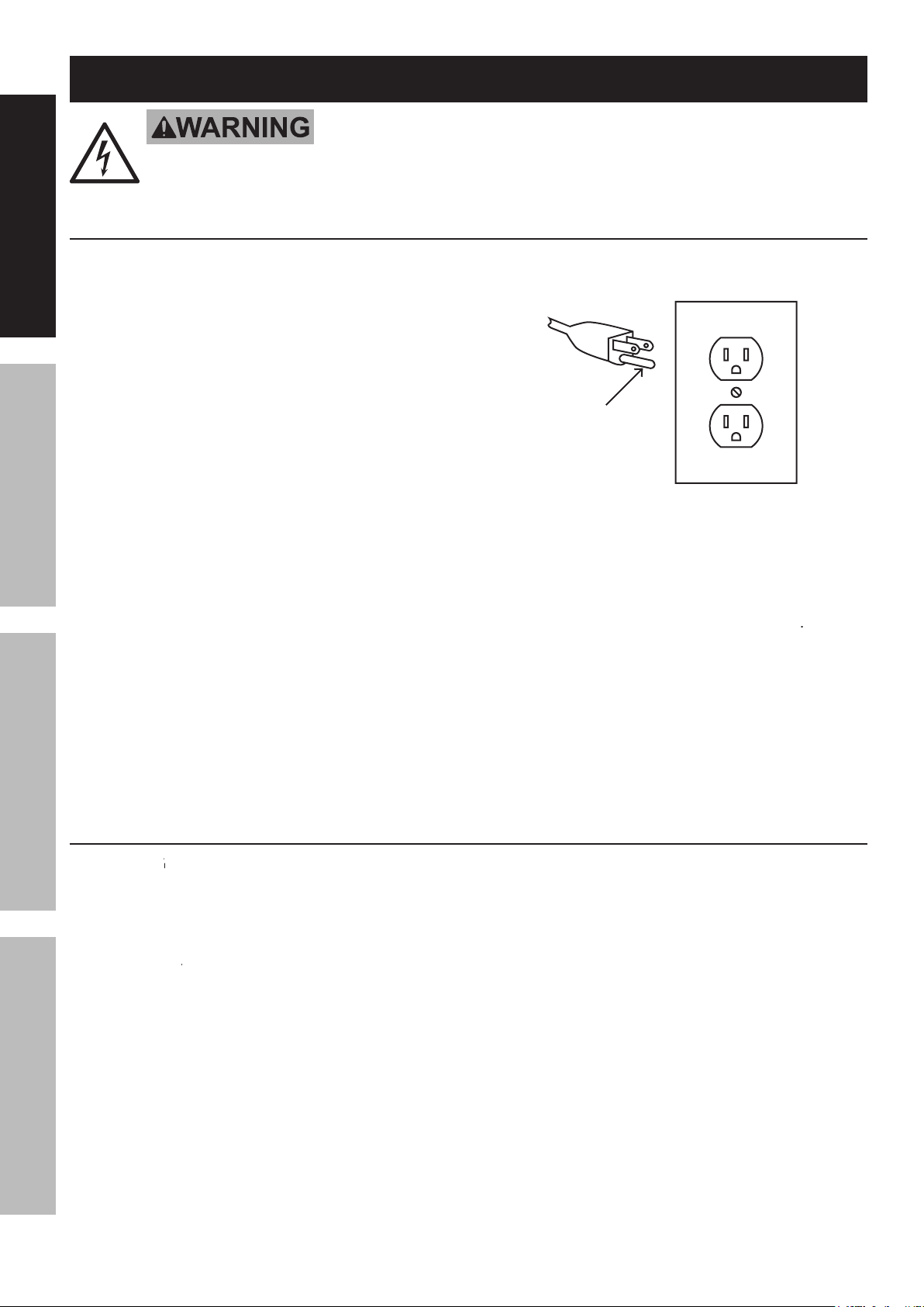
Grounding Instructions
Page 5

SAFETYOPERATIONMAINTENANCE SETUP
GUARD
Moving
for the specific hazards in the work area.
A
Avoid unintentional starting.
Your risk from these exposures varies,
work.
work
work
with
which cannot be built into this product,
Vibration Safety
Anyone using vibrating tools regularly or for an
SAVE THESE INSTRU
Page 6

SAFETY OPERATION MAINTENANCESETUP
V~ / 60Hz / 3.5A
Y
INFORMATION
section at the beginning of this
FROM A
and unplug the tool from its
For additional information regarding the parts listed in the following pages,
For additional information regarding the parts listed in the following pages,
Assembly/Mounting
A.
Backing Disc (5)
Specifications
Setup - Before Use:
Page 7

SAFETYOPERATIONMAINTENANCE SETUP
Align two Tabs on the Fence (63) with two
C
C
where Machine Screws are shown.
Angle Adjusting
Alignment
Page 8

SAFETY OPERATION MAINTENANCESETUP
Y
INFORMATION
section at the beginning of this
FROM A
and unplug the tool from its
Y
GUARD DISABLED, DAMAGED, OR
The Table (69) may be used as support
for both horizontal and vertical applications.
with Pivot Indicator
Angle
Adjusting
Washer
Washer (27)
Align the flat face of the Supporting Shaft with
Operating Instructions
Page 9

SAFETYOPERATIONMAINTENANCE SETUP
The Table (69) may be used for both
For these instructions and “General
C
on page 7
of this manual.
Adjusting the Sanding Belt Tracking
Adjusting the Sanding Belt Tracking
Page 10

SAFETY OPERATION MAINTENANCESETUP
Before using the Sanding Disc the first
Align perimeter of new Sanding Disc
firmly onto the Backing Disc.
Workpiece and Work Area Set Up
workpiece against the belt/disc to start sanding.
After use, turn off the tool, remove the
from the power supply. Clean and store the
Page 11

Maintenance and Servicing
P
FROM A
and unplug the tool from its
FROM
inspect the general
AFTER USE,
turn off the tool, remove the
A Dust Port (59) is located on the bottom of the
Apply a light coat of paste wax to the Table
WARNING! If the supply cord of this
SAFETYOPERATIONMAINTENANCE SETUP
Page 12

SAFETY OPERATION MAINTENANCESETUP
forward to loosen the belt.
V-Belt Replacement
from Outer Pulley Cover (9).
while turning the V-Belt by
WARNING!
V-Belt Tensioning
from Outer Pulley Cover (9).
Page 13

SAFETYOPERATIONMAINTENANCE SETUP
when sanding
V-Belt too tight.
Applying too much pressure
while sanding
while sanding
Page 14

SAFETY OPERATION MAINTENANCESETUP
V-Belt
Adjusting Bracket
Adjusting Bracket
Angle Pointer
Angle Pointer
Angle Adjusting Knob
Angle Adjusting Knob
AREFULL
ANY PARTS OF THE PRODUCT. IN FACT, THE MANUFACTURER AND/OR DISTRIBUTOR EXPRESSLY
ARISING OUT OF HIS OR HER REPAIRS TO THE ORIGINAL PRODUCT OR REPLACEMENT PARTS
If product has no serial number, record month and year of purchase instead.
If product has no serial number, record month and year of purchase instead.
Some parts are listed and shown for illustration purposes only,
Some parts are listed and shown for illustration purposes only,
Parts List and Diagram
Page 15

SAFETYOPERATIONMAINTENANCE SETUP
Assembly Diagram
Page 16

Limited 90 Day Warranty
THIS WARRANTY IS EXPRESSLY IN LIEU OF ALL OTHER
from causes not within the scope of our warranty, then you must bear the cost of returning the product.
 Loading...