

Page 1

WIRELESS HOME ALARM
94799
ASSEMBLY AND OPERATING INSTRUCTIONS
Due to continuing improvements, actual product ma y
differ slightly from the product described herein.
3491 Mission Oaks Blvd., Camarillo, CA 93011
Visit our W eb site at http://www.harborfreight.com
Copyright © 2006 by Harbor Freight Tools®. All rights reserved. No por tion of this
manual or any artwork contained herein may be reproduced in any shape or form
without the express written consent of Harbor Freight Tools.
For technical questions and replacement parts, please call 1-800-444-3353
Page 2

Specifications
Item Description
Function 6-station, wireless sensors detect an d s o und w h e n
Alarm Delay Time 5 seconds after sensor tripped
System Rang e From Sensors to Main Unit: 328 to 50 0 feet
Batteries Main Unit: 3-AA; Sensors: 3-SR54 (each); Remote
Main Unit LED lights and high pitch sound heard when
Key Chain
Remote Controls
Mounting Double-sided adhesive foam pads (supplied)
Dimensions Sensors: 1-7/8 (W) x 3-7/8 (L) x 1 /2 (T) inc he s
System Weight 1.45 lbs. (all components togeth er)
door or window is ope ne d .
control: 1-23A (12VDC)
numbered sen sor is tripped; Modes: Alarm/Off/Chime
System modes: On and Off; LED indicator.
Main Unit: 2-1/4 (L) x 4-1/4 (L) x 1 -3 /8 (D ) inche s
Magnetic Strip: 1/2 (W) x 3-1 /4 (L) x 3 /8 (T ) inches
Save This Manual
Y ou will need the manual f or the safety warnings and precautions, assembly instructions,
operating and maintenance procedures, parts list and diagram. Keep your invoice
with this manual. Write the invoice n umber on the inside of the front cover . Keep the
manual and invoice in a safe and dry place for future reference.
Safety Warnings and Precautions
WARNING: When using tool, basic safety precautions should alwa ys be followed
to reduce the risk of personal injury and damage to equipment.
Read all instructions before using this tool!
1. Keep work area clean. Cluttered areas invite injuries.
2. Observe work area conditions. Don’t e xpose components to rain. Keep
work area well lighted.
3. Keep children away. Children must never be allo wed in the work area or on
ladders.
4. Storing this product. When not in use, this product must be stored in a dry
location to protect system components.
5. Use the right product for the job. Do not use this alarm system to take the
place of a high-end alarm system where the protection of entry is of great
importance. There are certain applications for which this product was
designed. Do not modify this product, and do not use this tool for a purpose
for which it was not intended.
SKU 94799 For technical questions, please call 1-800-444-3353 Page 2
Page 3
6. Do not overreach. When using a ladder , keep proper f ooting and balance at
all times.
7. Stay alert. Watch what you are doing, use common sense.
8. Replacement parts and accessories. When servicing, use only identical
replacement parts. Use of any other parts will void the warranty. Only use
accessories intended for use with this tool. Appro v ed accessories are
available from Harbor Freight Tools.
Note: P erf ormance of this product may v ary depending on variations in Sensor and
Main Unit battery power.
Warning: The warnings, cautions, and instructions discussed in this instruction
manual cannot cover all possible conditions and situations that may occur. It
must be understood by the operator that common sense and caution are factors
which cannot be built into this product, but m ust be supplied by the operator.
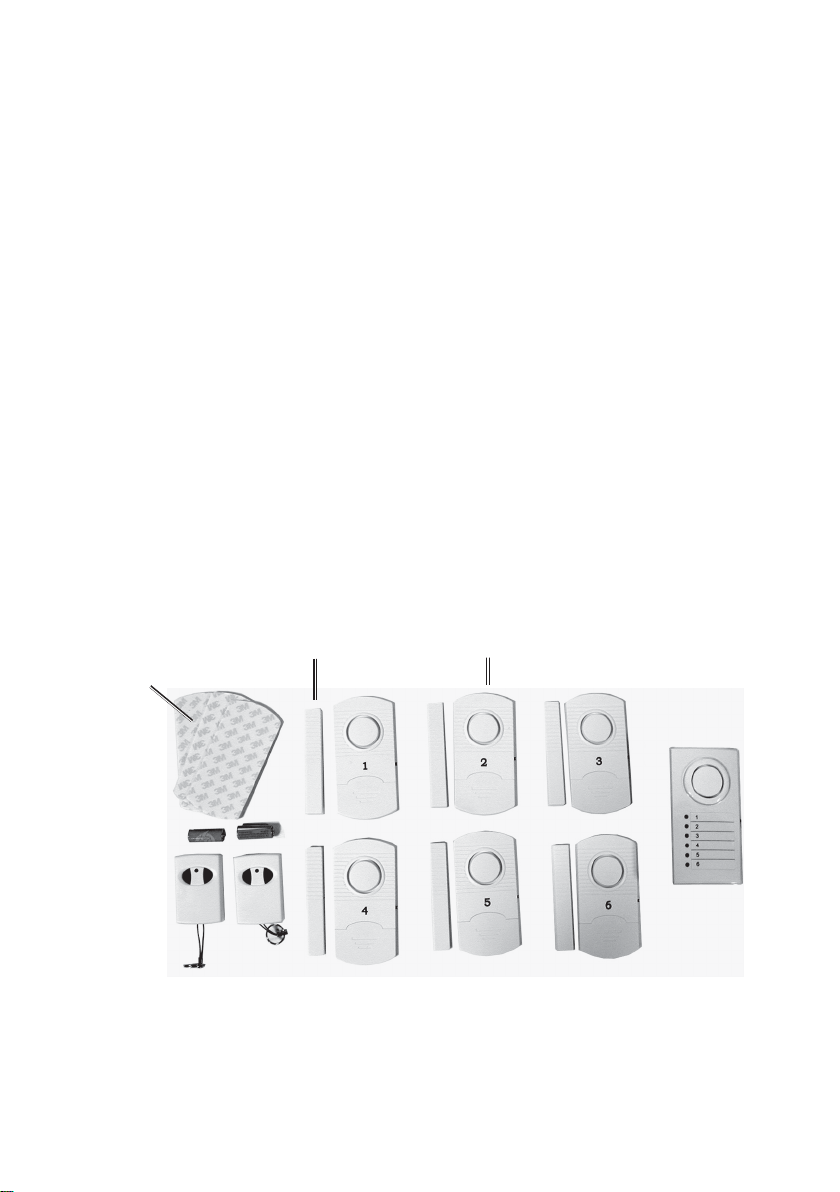
Unpacking
When unpacking, check to make that all the Wireless Home Alarm System components
are included. See photo belo w. If any parts are missing or broken, please call Harbor
Freight Tools at the number on the cov er of this manual.
Adhesive Strips
for Sensors and
Main Unit
Remote Controls
Magnetic Strip
and Batteries
(above)
Installation
Sensors 1 to 6
Main Unit
1. Snap off the back cover of the Main Unit and install three, quality AA batteries
(not supplied) into the Main Unit. P a y attention to the battery polarity
(+ and -). See photo below-left.
SKU 94799 For technical questions, please call 1-800-444-3353 Page 3
Page 4

2. Unscrew the back co ver of each Remote Control and insert the battery
(supplied) into the back of the Remote. P a y attention to the battery polarity
(+ and -). See photo below-right.
Main Unit
Remote Control
Note: Each Sensor comes with a battery installed. Since the internal battery is only
used when the Magnetic Strip is moved away (sensor tripped), it should last two
years. The batteries of the Remote Controls should also last two years.
3. Select the six Sensor locations. They should be placed in the most likely point
of entry , (i.e ., doors or windows), or exit points, if used to protect entry to
areas such as to swimming pools.
4. Select an area on the movable part of the door or window where the Sensor
can be mounted flat. The Magnetic Strip must be mounted parallel to, and no
more than 1/4 inch from, the Sensor. The Sensor and Magnetic Strip may be
mounted upside down to accommodate door or window configuration.
Window Frame
Window
Door Frame
Door
Note: It is recommended to test each Sensor with its Magnetic Strip before mounting.
Refer to the Operation section on page 5.
5. P eel off the backing to one of the Adhesive Pads and squarely stick it to the
back of one of the Sensors.
6. P eel off the remaining Adhesive P ad bac king and secure the Sensor to its
mounting location.
SKU 94799 For technical questions, please call 1-800-444-3353 Page 4
Page 5
7. P eel the Adhesiv e P ad backing from one of the Magnetic Strips and mount it
parallel to, and no more than 1/4 inch from, the Sensor . See photos at the
bottom of page 4.
8. Repeat steps 5 to 7 for each Sensor and Magnetic Strip.
9. Using a small round-head screw (not supplied), screw into the desired
mounting location. Place the hole in the bac k of the Main Unit o v er the scre w,
and slide the unit down to lock in place.
Note: Not all the Sensors need to be used f or the Wireless Home Alarm to work.
Operation
Controls and Indicators
Main Unit
Alarm - Loud noise
Sensor LED lights
when Sensor tripped.
when Sensor tripped.
Off - Unit turned off.
Chime - Ding-dong
sound when Sensor
tripped.
Sensor
Off - Sensor turned off.
RF+Alarm - Sensor On;
Sensor Sounds when
tripped. Sensor # lights on
Main Unit.
RF - Sensor On; No
sound when tripped.
Sensor # lights on
Main Unit.
Setup for Operation
1. On each Sensor , push the slide switch to the desired oper ating position:
RF+Alarm (signal and sound) or RF (signal, no sound).
2. On the Main Unit, push the slide switch to the desired operating position:
Alarm (loud noise) or Chime (Ding-dong sound).
SKU 94799 For technical questions, please call 1-800-444-3353 Page 5
Page 6

Arm Alarm System
On the Remote Control, press the ON button. The LED on the Remote Control will
temporarily turn on. This can be done from outside the house or other protected
structure.
Disarm Alarm System
On the Remote Control, press the OFF button. The LED on
the Remote Control will temporarily turn on. This can be
done from outside the house or other protected structure.
Remote Control
Troubleshooting
Problem Possible Cause Probable Solution
When system is armed,
one sensor does not sound
or signal Main Unit when
Magnet Strip is moved.
One Sensor continues to
sound alarm even through
the door is closed.
Main Unit does not detect
any intrusions from any
Sensors.
1. Sensor is turned Off.
2. Battery is dead.
3. Main Unit is turned Off.
Magnetic Strip is placed too
far from Sensor.
1. Main Unit batteries are
dead.
2. Main Unit is placed too
far from the Sensors.
1. Turn Sensor On.
2. Replace battery.
3. Turn Main Unit On.
Move Magnetic Strip to within
¼” of the Sensor.
1. Replace batteries.
2. Move Main Unit closer to
the Sensors.
Maintenance
1. P eriodically test each Sensor and Main Unit for alarm indication and sound.
2. P eriodically test each Remote Control for Main Unit activation and
deactivation.
3. Replace Main Unit batteries at least once a year . Replace other batteries as
required.
SKU 94799 For technical questions, please call 1-800-444-3353 Page 6
Page 7

(7)
(4)
Parts List
Item Description Qty
1.
2. Sensor 6
3. Magnetic Strip 6
4. Battery, Remote Control 2
5. Remote Control 2
6. Battery, Sensor 6
7. Pads, Adhesive 6
Main Unit 1
Parts Photo
(3)
(2)
(3)
(2)
(4)
(5)(5)
(3) (3)
(3)
(2)
(2)
(3)
(2)
(1)
(2)
(6) Sensor Battery not shown.
NOTE: Some parts are listed and shown for illustration purposes only and are not
available individually as replacement parts.
PLEASE READ THE FOLLOWING CAREFULLY
THE MANUFACTURER AND/OR DISTRIBUTOR HAS PROVIDED THE PARTS DIAGRAM
IN THIS MANUAL AS A REFERENCE TOOL ONLY. NEITHER THE MANUFACTURER NOR
DISTRIBUTOR MAKES ANY REPRESENTATION OR WARRANTY OF ANY KIND TO THE
BUYER THAT HE OR SHE IS QUALIFIED TO MAKE ANY REPAIRS TO THE PRODUCT OR
THAT HE OR SHE IS QUALIFIED TO REPLACE ANY PARTS OF THE PRODUCT. IN FA CT,
THE MANUFACTURER AND/OR DISTRIBUTOR EXPRESSLY STATES THat ALL REPAIRS
AND PARTS REPLACEMENTS SHOULD BE UNDERTAKEN BY CERTIFIED AND
LICENSED TECHNICIANS AND NOT BY THE BUYER. THE BUYER ASSUMES ALL RISK
AND LIABILITY ARISING OUT OF HIS OR HER REPAIRS TO THE ORIGINAL PRODUCT
OR REPLACEMENT PARTS THERET O , OR ARISING OUT OF HIS OR HER INSTALLA TION
OF REPLACEMENT PARTS THERETO.
SKU 94799 For technical questions, please call 1-800-444-3353 Page 7
 Loading...