

Page 1
3/8” REVERSIBLE AIR DRILL
®
Model 94585
Due to continuing improvement, actual product may differ slightly from the product described herein.
ASSEMBLY and OPERATING INSTRUCTIONS
3491 Mission Oaks Blvd., Camarillo, CA 93011
Visit our Web Site at www.harborfreight.com
Copyright© 2006 by Harbor F reight Tools®. All rights reserved. No portion of this manual
or any artwork contained herein may be reproduced in any shape or form without the
express written consent of Harbor F reight T ools .
SKU 94585 For technical questions please call 1-800-444-3353. Page 1
For technical questions and replacement parts please call 1-800-444-3353.
Page 2

SPECIFICATIONS
No Load Speed 1700 RPM
Max. Recommended Air Pressure 90 PSI
Air Consumption 5 CFM
Air Inlet 1/4” -18 NPT
Chuck T ype 3 Jaw Keyed Chuck
Chuck Size 3/8”
Weight 2.4 lbs.
SAVE THIS MANUAL
You will need the manual for the safety warnings and cautions, assembly instructions, operating
procedures, maintenance procedures, trouble shooting, parts list, and diagram. Keep your invoice
with this manual. Write the invoice number on the inside of the front cover . Keep both this manual
and your invoice in a safe, dry place for future reference.
SAFETY W ARNING & CAUTIONS
WARNING: When using pneumatic equipment, basic safety precautions should always be
followed to reduce the risk of personal injury and hazards due to over pressurization.
READ ALL INSTRUCTIONS BEFORE USING THIS TOOL!
1. KEEP WORK AREA CLEAN. Cluttered, damp or wet areas invite injuries.
2. KEEP CHILDREN AWAY. Children must never be allowed in the work area. Do not let them
handle machines, tools, or hoses.
3. STORE IDLE EQUIPMENT. When not in use, tools must be locked up in a dry location to
inhibit rust. Always lock up tools and keep out of reach of children.
4. DO NOT FORCE THE TOOL. It will do the job better and more safely at the rate for which it
was intended. Do not use inappropriate attachments in an attempt to exceed the tool’s
capacities.
5. USE THE RIGHT TOOL FOR THE JOB. Do not attempt to force a small tool or attachment
to do the work of a larger industrial tool. Do not use a tool for a purpose for which it was not
intended.
6. DRESS SAFELY. Do not wear loose clothing or jewelry as they can be caught in moving
parts. Non-skid footwear is recommended. Wear restrictive hair covering to contain long hair.
7. USE EYE, BREATHING AND EAR PROTECTION. Wear ANSI approved impact safety
goggles, ANSI approved hearing protectors, and ANSI approved dust mask or respirator
when using this product. ANSI approved safety impact eye glasses, hearing protectors, and
dust masks and respirators are available from Harbor Freight Tools.
SKU 94585 For technical questions please call 1-800-444-3353. Page 2
Page 3

8. DO NOT ABUSE THE POWER CORD. Do not yank compressor’s cord to disconnect it
from the receptacle. Do not carry tools by the cord.
9. DO NOT OVERREACH. Keep proper footing and balance at all times. Do not reach over or
across running machines.
10. MAINTAIN TOOLS WITH CARE. Keep tools sharp and clean for better and safer
performance. Follow instructions for lubricating and changing accessories. Inspect
compressor’s cord periodically and, if damaged, have them repaired by an authorized
technician. Inspect all hoses for leaks prior to use. The handles must be kept clean, dry, and
free from oil and grease at all times.
11. REMOVE ADJUSTING KEYS AND WRENCHES. Make it a habit to check that keys and
adjusting wrenches are removed from the tool or machine work surface before plugging it in.
12. AVOID UNINTENTIONAL STARTING. Do not carry any tool with your finger on the trigger,
whether it is connected to the compressor or not.
13. ST AY ALERT. Watch what you are doing; use common sense. Do not operate any tool when
you are tired.
14. CHECK DAMAGED PARTS. Before using any tool, any part that appears damaged should
be carefully checked to determine that it will operate properly and perform its intended
function. Check for alignment and binding of moving parts; any broken parts or mounting
fixtures; and any other condition that may affect proper operation. Any part that is damaged
should be properly repaired or replaced by a qualified technician. Do not use the tool if any
switch does not turn on and off properly.
15. REPLACEMENT PARTS AND ACCESSORIES. When servicing, use only identical
replacement parts. Use of any other parts will void the warranty. Only use accessories
intended for use with this tool. Approved accessories are available from Harbor Freight Tools.
16. DO NOT OPERATE TOOL IF UNDER THE INFLUENCE OF ALCOHOL OR DRUGS.
Read warning labels on prescriptions to determine if your judgment or reflexes are impaired
while taking drugs. If there is any doubt, do not operate the tool.
17. DRAIN THE COMPRESSOR USED TO POWER THE TOOL EVERY DAY. Do not allow
moisture to build up inside the compressor. Do not allow compressor to sit pressurized for
longer than one hour.
18. MAKE SURE ALL EQUIPMENT IS RATED TO THE APPROPRIATE CAPACITY. Make
sure that regulator is set at least 10 PSI lower than the lowest rated piece of equipment you
are using.
19. MAINTAIN PRODUCT WITH CARE. Keep clean and dry for better and safer performance.
20. WARNING: The warnings and precautions discussed in this manual cannot cover all
possible conditions and situations that may occur. It must be understood by the operator that
common sense and caution are factors which cannot be built into this product, but must be
supplied by the operator.
SKU 94585 For technical questions please call 1-800-444-3353. Page 3
Page 4
SPECIFIC PRODUCT W ARNINGS AND PRECAUTIONS
1. USE CLEAN, DRY, REGULATED COMPRESSED AIR AT 90 PSI. Do not exceed the
recommended 90 PSI. Never use oxygen, carbon dioxide, combustible gases or any
other bottled gas as a power source for this tool.
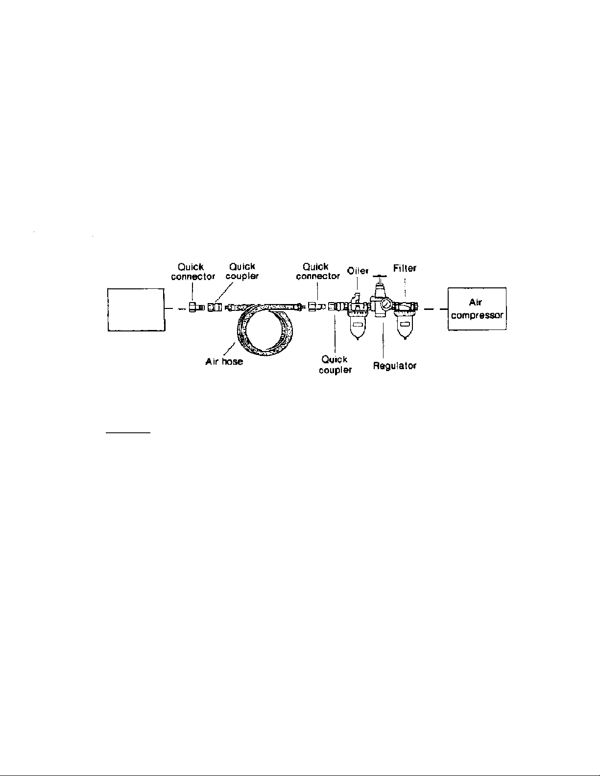
2. WHEN CONNECTING TO THE AIR SUPPLY:
A. Wrap approximately 4” of Teflon tape around the male threads of a 1/4” NPT Quick
Connector (not provided). Then, wrench tighten the Quick Connector into the Air Inlet.
B. If an automatic oiler is not used, add two drops of oil into the Quick Connector.
C. Turn on the compressor and set the regulator to the pressure recommended for this
tool (90 PSI).
Air
Drill
Airline Oiler Assembly
3.
4. MAINT AIN A SAFE WORK ENVIRONMENT. Keep work area well lit. Make sure there is
5. DO NOT FORCE THE EQUIPMENT. This product will do the work better and safer at
6. AVOID UNINTENTIONAL STARTING. Make sure you are prep ared to begin work before
7. NEVER POINT TOOL AT PEOPLE OR ANIMALS.
8. WARNING: Some dust created by power sanding, sawing, grinding, drilling, and other
ALWAYS DISCONNECT TOOL FROM ITS COMPRESSED AIR SUPPLY SOURCE
BEFORE PERFORMING ANY SERVICES OR MAINTENANCE such as cleaning the
tool, changing chisels or punches, moving to a different work location, handing the tool to
another person, etcetera. Caution: Af ter disconnecting the TOOL from the air
compressor, the TOOL will still be pressurized. Point the TOOL onto an extra piece of
work surface and depress the trigger until all pressure is released.
adequate surrounding work space. Use this product in a well ventilated area. Do not
operate this product in the presence of flammable liquids, gasses, or dust.
the speed and capacity for which it was designed.
depressing the Trigger.
construction activities, contain chemicals known (to the State of California) to cause
cancer, birth defect s or other reproductive harm. Some examples of these chemicals
SKU 94585 For technical questions please call 1-800-444-3353. Page 4
Page 5

(Continued from page 4)
are: lead from lead-based paints, crystalline cilica from bricks and cement or other masonry
products, arsenic and chromium from chemically treated lumber. Your risk from these
exposures varies, depending on how often you do this type of work. To reduce your exposure to
these chemicals; work in a well ventilated area, and work with approved safety equipment, such
as those dust masks that are specially designed to filter out microscopic particles.
(California Health & Safety Code 25249.5, et seq.)
UNPACKING
Your Air Drill comes completely assembled. Included is a chuck key for use with this tool.
Check to make sure everything is included. If any parts are missing or broken, please call
Harbor Freight Tools at the number on the cover of this manual.
ASSEMBLY
Your Air Drill is completely assembled. Follow the steps below to install drill bits and prepare for
the operation of your Air Drill.
Drill Bit Installation
Step 1: Select the drill bit needed for the drilling you wish to perform.
Step 2: Open up the Jaws of the Drill by turning the DRILL CHUCK (#2) as shown in Figure 1.
Motor Housing
(#17)
(#16)
Drill Chuck
(#2)
Figure 1 — Opening the Jaws
Step 3: When the Jaws are open wide enough to insert the drill bit, slide the bit into the DRILL
CHUCK as far as possible.
SKU 94585 For technical questions please call 1-800-444-3353. Page 5
Page 6

Step 4: By hand, turn the DRILL CHUCK to tighten the Jaws as shown in Figure 2.
Motor Housing
(#17)
(#16)
Drill Chuck
(#2)
Drill Bit
Figure 2 — Tightening the Jaws
Step 5: Insert the Chuck Key into one of the three chuck holes in the DRILL CHUCK as shown
in Figure 3, mating the teeth of the Chuck Key with the teeth of the DRILL CHUCK.
Drill Chuck
(#2)
Drill Bit
Chuck Hole
Figure 3 — Using the Chuck toTighten the Jaws
Step 6: Turn the Chuck Key to tighten the Jaws. Make sure the Jaws are tight.
Step 7: Put the Chuck Key in a safe place. Do not lose the Chuck Key.
SKU 94585 For technical questions please call 1-800-444-3353. Page 6
Page 7

Air Connection
Step 1: Remove the plastic cap from the AIR INLET (#29).
Step 2: You will need a Union fitting (sold separately) before you can connect your Air Drill to
an air compressor. Attach the Union fitting to the AIR INLET.
Step 3: Attach an Air Coupler (sold separately) to the Union fitting if desired. This is a useful
accessory as it allows quick-coupling action when using a variety of tools with the
same air compressor.
Step 4: Your Air Drill is ready for use.
OPERATION
Setup
Frequent, but not excessive, lubrication is required for best performance. Oil added through the
airline connection will lubricate internal parts. An automatic airline oiler is recommended but oil
may be added manually before every operation or after about 1 hour of continuous use. Only a
few drops of oil at a time are necessary. Too much oil will collect inside the tool and be blown
out during the exhaust cycle. ONLY USE PNEUMATIC TOOL OIL. Do not use detergent oil or
additives as these lubricants will cause accelerated wear to the seals in the tool.
Dirt and water in the air supply are major causes of pneumatic tool wear. Use a filter/oiler for
better performance and longer life. The filter must have adequate flow capacity for the specific
application. Consult the manufacturer’s instructions for proper maintenance of your filter.
The connector on the tool must not hold pressure when the air supply is disconnected. If the
wrong fitting is used, the tool can remain charged with air after being disconnected and still be
able to drive a fastener. See Airline Oiler Assembly on page 4 for the recommended accessories
and connection order.
SKU 94585 For technical questions please call 1-800-444-3353. Page 7
Page 8

Using The Air Drill
Step 1: Mark the material you wish to drill at the spot for the hole. Make sure your drill bit is
the correct size for the hole you need to make.
Step 2: Clamp the material in a vise to make sure the material does not move or begin to spin
while drilling.
Step 3: Wear eye protection to guard against flying wood or metal.
Step 4: Set the compressor’s pressure regulator to 90 PSI. Do not set the compressor’s outlet
regulator over 90 PSI.
Step 5: Connect the Air Drill to the air compressor’s hose. If leaking is detected, disconnect
the air hose and repair before use.
Step 6: Grip the Air Drill firmly. Place the drill bit on the spot
marked in Step 1.
Step 7: To begin drilling, press the TRIGGER (#18).
Step 8: Your Air Drill has a variable speed for drilling. To vary the speed of the drilling action,
vary the pressure on the TRIGGER.
Step 9: Drill only as deep as necessary . Do not drill deeper than necessary into walls or other
areas where you cannot identify any possible hazards behind the drilling surface.
Step 10: When you have drilled the hole, remove the drill bit from the hole while the Air Drill is still
spinning. This is to prevent the drill getting caught in the hole and causing damage.
Step 11: If the drill bit does get caught while you are drilling,
immediately release the TRIGGER.
Do not operate the Air Drill
before placing the drill bit
Do not touch the DRILL
CHUCK or the drill bit while
the Air Drill is spinning.
CAUTION
on the material.
WARNING
SKU 94585 For technical questions please call 1-800-444-3353. Page 8
Page 9

Step 12: Flip the REVERSE VALVE (#20) to the “R” position as shown in Figure 5. This will
reverse the rotation of the drill, allowing you to back out your drill bit.
Figure 5 — Reversing the Rotation of the Drill Bit
Step 13: Lightly press the TRIGGER until the drill bit spins free. Remove the Air Drill.
Step 14: Flip the REVERSE VALVE back to the “F” position.
MAINTENANCE
It is recommended that you use an Airline Oiler with your Air Drill. If you do not use an Airline
Oiler, follow the step s below to maint ain and prolong the life of your tool.
Step 1: Disconnect the Air Drill from the air hose.
Step 2: Apply a few drops of PNEUMATIC TOOL OIL
through the air line before each use, or every
hour if used continuously .
Step 3: Apply a few drops of oil to the TRIGGER (#18).
Work the TRIGGER a few times to lubricate.
Do not use detergent oil or
additives as these lubricants will
cause accelerated wear to the
CAUTION
seals in the tool.
SKU 94585 For technical questions please call 1-800-444-3353. Page 9
Page 10

Step 4: Twice a month, apply a few drops of oil to the Jaws and REVERSE VALVE (#24) as
A
shown in Figure 6. Open and close the Jaws a few times to lubricate.
Jaws
Reverse Valve
(#20)
(#24)
Trigger
(#20)
(#18)
ir Inlet
Figure 6 — Lubrication Points
(#29)
(#31)
PARTS LIST
Item Description QTY Item Description QTY
1 Flat head socket cap screw 1 16 Motor Housing 1
2 Drill Chuck 1 17 Cup Point Set Screw 1
3 Clamp Nut 1 18 Trigger 1
4 Flat Washer 1 19 Valve Spring 1
5 Ball Bearing 2 20 Reverse Valve 1
6 Planet Gear Carrier 1 21 O-Ring 1
7 Planet Gear with Bushing 3 22 Reverse Valve Bushing 1
8 Internal Gear 1 23 Throttle V alve 1
9 Bearing Case 1 24 O-Ring 1
10 Ball Bearing 2 25 O-Ring 1
11 End Plate 2 26 Roll Pin 1
12 Rotor 1 27 Exhaust Diffuser 1
13 Rotor Blade 5 28 Self-Tapping
14 Cylinder 1 Button Head Screw 2
15 Motor Alignment Pin 1 29 Air Inlet with Screen 1
30 Chuck Key 1
NOTE: Some parts are listed and shown for illustration purposes only, and are not available
iindividually as replacement parts.
SKU 94585 For technical questions please call 1-800-444-3353. Page 10
Page 11

30
ASSEMBLY DIAGRAM
DISCLAIMER
PLEASE READ THE FOLLOWING CAREFULLY
THE MANUFACTURER AND/OR DISTRIBUTOR HAS PROVIDED THE PARTS DIAGRAM
IN THIS MANUAL AS A REFERENCE TOOL ONLY. NEITHER THE MANUFACTURER NOR
DISTRIBUTOR MAKES ANY REPRESENTATION OR WARRANTY OF ANY KIND TO THE
BUYER THAT HE OR SHE IS QUALIFIED TO MAKE ANY REPAIRS TO THE PRODUCT OR
THAT HE OR SHE IS QUALIFIED TO REPLACE ANY PARTS OF THE PRODUCT. IN FACT,
THE MANUFACTURER AND/OR DISTRIBUTOR EXPRESSLY STATES THE ALL REPAIRS
AND P ARTS REPLACEMENTS SHOULD BE UNDERTAKEN BY CERTIFIED AND LICENSED
TECHNICIANS AND NOT BY THE BUYER. THE BUYER ASSUMES ALL RISK AND LIABILITY
ARISING OUT OF HIS OR HER REPAIRS TO THE ORIGINAL PRODUCT OR
REPLACEMENT PARTS THERETO, OR ARISING OUT OF HIS OR HER INSTALLATION
OF REPLACMENT PARTS THERETO.
SKU 94585 For technical questions please call 1-800-444-3353. Page 11
Page 12

WARRANTY
LIMITED 1 YEAR
WARRANTY
Harbor Freight Tools Co. makes eve ry effort to assure that its products meet high quality and durability standards,
and warrants to the original purchaser that this product is free from defects in materials and workmanship for
the period of one year from the date of purchase. This warranty does not apply to damage due directly or
indirectly to misuse, abuse, negligence or accidents; repairs or alterations outside our facilities; or to lack of
maintenance. W e shall in no event be liable for death, injuries to persons or property , or f or incidental, contingent,
special or consequential damages arising from the use of our product. Some states do not allow the e xclusion
or limitation of incidental or consequential damages, so the above limitation of exclusion may not apply to
you.THIS WARRANTY IS EXPRESSLY IN LIEU OF ALL OTHER WARRANTIES, EXPRESS OR IMPLIED,
INCLUDING THE WARRANTIES OF MERCHANTABILITY AND FITNESS.
To take adv antage of this warranty, the product or part must be returned to us with transpor tation charges
prepaid. Proof of purchase date and an explanation of the complaint m ust accompany the merchandise . If our
inspection verifies the defect, we will either repair or replace the product at our election or we may elect to
refund the purchase price if we cannot readily and quickly provide you with a replacement. We will return
repaired products at our expense, but if we determine there is no defect, or that the defect resulted from
causes not within the scope of our wa rranty, then you must bear the cost of returning the product.
This warranty gives you specific legal rights and you may also have other rights which vary from state to state.
3491 Mission Oaks Blvd. • PO Box 6009 • Camarillo, CA 93011 • (800) 444-33533491 Mission Oaks Blvd. • PO Box 6009 • Camarillo, CA 93011 • (800) 444-3353
3491 Mission Oaks Blvd. • PO Box 6009 • Camarillo, CA 93011 • (800) 444-3353
3491 Mission Oaks Blvd. • PO Box 6009 • Camarillo, CA 93011 • (800) 444-33533491 Mission Oaks Blvd. • PO Box 6009 • Camarillo, CA 93011 • (800) 444-3353
SKU 94585 For technical questions please call 1-800-444-3353. Page 12
 Loading...