

Harbor Freight Tools 94071 Owner's Manual

3″ MINI TOOL GRINDER
94071
SET UP AND OPERATING INSTRUCTIONS
Visit our website at: http://www.harborfreight.com
Read this material before using this product.
Failure to do so can result in serious injury.
SAVE THIS MANUAL.
Copyright© 2005 by Harbor Freight Tools®. All rights reserved. No portion of this manual or any artwork
contained herein may be reproduced in any shape or form without the express written consent of
Harbor Freight Tools. Diagrams within this manual may not be drawn proportionally. Due to continuing
improvements, actual product may differ slightly from the product described herein. Tools required for
assembly and service may not be included.
For technical questions or replacement parts, please call 1-800-444-3353.
Manual Revised 11a

CONTENTS
IMPORTANT SAFETY
INFORMATION ........................... 3
GENERAL TOOL SAFETY
WARNINGS ..................................... 3
GROUNDING INSTRUCTIONS .... 5
110-120 V~ GROUNDED TOOLS:
TOOLS WITH THREE PRONG
PLUGS ............................................ 5
GRINDER SAFETY WARNINGS ....... 6
SPECIFICATIONS ......................... 8
UNPACKING ................................. 8
ASSEMBLY INSTRUCTIONS ....... 8
TO ATTACH THE RIGHT
MOVABLE TOOL REST: ................8
TO ATTACH THE SPARK SHIELDS: 9
TO MOUNT THE GRINDER ON A
WORKBENCH: ............................... 9
OPERATING INSTRUCTIONS ... 10
INSPECTION, MAINTENANCE,
AND CLEANING ........................11
PARTS LIST ................................ 12
ASSEMBLY DIAGRAM ............... 13
LIMITED 90 DAY WARRANTY ... 14
SKU 94071 For technical questions, please call 1-800-444-3353 PAGE 2
SAVE THIS MANUAL
Keep this manual for the safety
warnings and precautions, assembly,
operating, inspection, maintenance
and cleaning procedures. Write the
product’s serial number in the back of
the manual near the assembly diagram
(or month and year of purchase if
product has no number). Keep this
manual and the receipt in a safe and
dry place for future reference.
IMPORTANT SAFETY
INFORMATION
In this manual, on the labeling,
and all other information
provided with this product:
This is the safety alert
symbol. It is used to alert
you to potential personal
injury hazards. Obey all
safety messages that
follow this symbol to avoid
possible injury or death.
CAUTION, used
with the safety
alert symbol, indicates a
hazardous situation which, if
not avoided, could result in
minor or moderate injury.
NOTICE is used to
address practices
not related to personal injury.
CAUTION, without
the safety alert
symbol, is used to address
practices not related to
personal injury.
General Tool Safety Warnings
WARNING Read all safety
warnings and instructions.
Failure to follow the warnings and
instructions may result in electric
shock, re and/or serious injury.
Save all warnings and
instructions for future reference.
1. KEEP GUARDS IN PLACE
and in working order.
DANGER indicates
a hazardous
situation which, if not
avoided, will result in death or
serious injury.
WARNING
indicates a
hazardous situation which, if
not avoided, could result in
death or serious injury.
SKU 94071 For technical questions, please call 1-800-444-3353 PAGE 3
2. REMOVE ADJUSTING KEYS
AND WRENCHES. Form habit
of checking to see that keys and
adjusting wrenches are removed
from tool before turning it on.
3. KEEP WORK AREA CLEAN.
Cluttered areas and benches
invite accidents.
4. DON’T USE IN DANGEROUS
ENVIRONMENT. Don’t use
power tools in damp or wet
locations, or expose them to rain.
Keep work area well lighted.

5. KEEP CHILDREN AWAY. All
visitors should be kept safe
distance from work area.
6. MAKE WORKSHOP KID PROOF
with padlocks, master switches,
or by removing starter keys.
7. DON’T FORCE TOOL. It will do
the job better and safer at the
rate for which it was designed.
jewelry which may get caught in
moving parts. Nonslip footwear is
recommended. Wear protective
hair covering to contain long hair.
11. ALWAYS USE SAFETY GLASSES.
Also use face or dust mask
if grinding operation is dusty.
Everyday eyeglasses only have
impact resistant lenses, they
are NOT safety glasses.
8. USE RIGHT TOOL. Don’t force
tool or attachment to do a job
for which it was not designed.
RECOMMENDED MINIMUM WIRE
GAUGE FOR EXTENSION CORDS
(120 VOLT)
NAMEPLATE
AMPERES
(at full load)
0 – 6 18 16 16 14
6.1 – 10 18 16 14 12
10.1 – 12 16 16 14 12
12.1 – 16 14 12
EXTENSION CORD
LENGTH
25’ 50’ 100’ 150’
TABLE A
9. USE PROPER EXTENSION CORD.
Make sure your extension cord
is in good condition. When using
an extension cord, be sure to use
one heavy enough to carry the
current your product will draw. An
undersized cord will cause a drop in
line voltage resulting in loss of power
and overheating. Table A shows
the correct size to use depending
on cord length and nameplate
ampere rating. If in doubt, use the
next heavier gauge. The smaller the
gauge number, the heavier the cord.
10. WEAR PROPER APPAREL.
Do not wear loose clothing,
neckties, rings, bracelets, or other
12. DON’T OVERREACH. Keep proper
footing and balance at all times.
13. MAINTAIN TOOLS WITH CARE.
Keep tools sharp and clean for
best and safest performance.
Follow instructions for lubricating
and changing accessories.
14. DISCONNECT TOOLS before
servicing; when changing
accessories, such as blades,
bits, cutters, and the like.
15. REDUCE THE RISK OF
UNINTENTIONAL STARTING.
Make sure switch is in off
position before plugging in.
16. USE RECOMMENDED
ACCESSORIES. Consult the
owner’s manual for recommended
accessories. The use of
improper accessories may cause
risk of injury to persons.
17. NEVER STAND ON TOOL.
Serious injury could occur if the
tool is tipped or if the grinding tool
is unintentionally contacted.
18. CHECK DAMAGED PARTS. Before
further use of the tool, a guard or
other part that is damaged should be
carefully checked to determine that
it will operate properly and perform
SKU 94071 For technical questions, please call 1-800-444-3353 PAGE 4
its intended function – check for
alignment of moving parts, binding
of moving parts, breakage of parts,
mounting, and any other conditions
that may affect its operation. A guard
or other part that is damaged should
be properly repaired or replaced.
19. DIRECTION OF FEED. Feed
work into a blade or cutter
against the direction of rotation
of the blade or cutter only.
20. NEVER LEAVE TOOL RUNNING
UNATTENDED. TURN POWER OFF.
GROUNDING INSTRUCTIONS
3. Improper connection of the
equipment-grounding conductor can
result in a risk of electric shock. The
conductor with insulation having
an outer surface that is green with
or without yellow stripes is the
equipment-grounding conductor. If
repair or replacement of the electric
cord or plug is necessary, do not
connect the equipment-grounding
conductor to a live terminal.
4. Check with a qualied electrician or
service personnel if the grounding
instructions are not completely
understood, or if in doubt as to
whether the tool is properly grounded.
TO PREVENT
ELECTRIC SHOCK
AND DEATH FROM
INCORRECT GROUNDING
WIRE CONNECTION
READ AND FOLLOW THESE
INSTRUCTIONS:
110-120 V~ Grounded Tools:
Tools with Three Prong Plugs
1. In the event of a malfunction or
breakdown, grounding provides a
path of least resistance for electric
current to reduce the risk of electric
shock. This tool is equipped with an
electric cord having an equipmentgrounding conductor and a grounding
plug. The plug must be plugged into
a matching outlet that is properly
installed and grounded in accordance
with all local codes and ordinances.
5. Use only 3-wire extension cords
that have 3-prong grounding
plugs and 3-pole receptacles
that accept the tool’s plug.
6. Repair or replace damaged
or worn cord immediately.
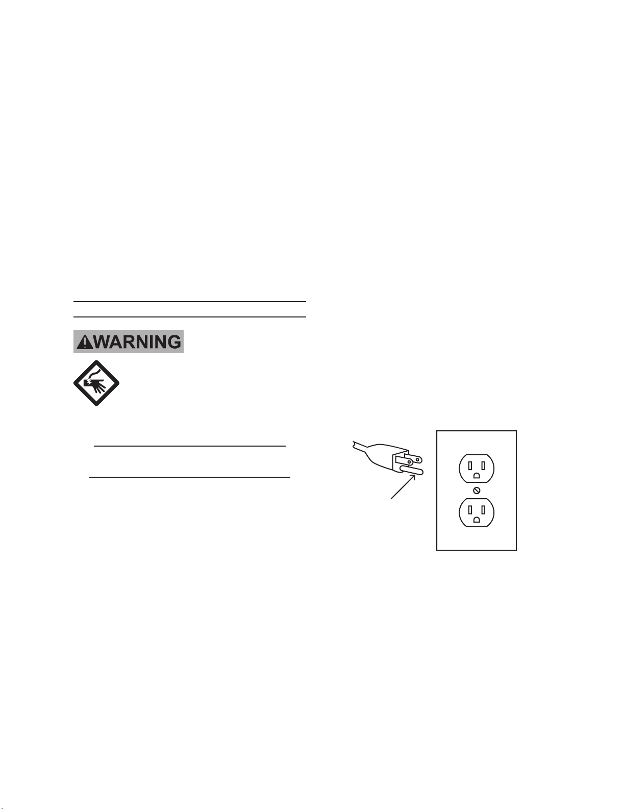
Grounding
Pin
125 V~ 3-Prong Plug and Outlet
(for up to 125 V~ and up to 15 A)
7. This tool is intended for use on a
circuit that has an outlet that looks
like the one illustrated above in
125 V~ 3-Prong Plug and Outlet.
2. Do not modify the plug provided
– if it will not t the outlet, have
the proper outlet installed by
a qualied electrician.
SKU 94071 For technical questions, please call 1-800-444-3353 PAGE 5
8. The tool has a grounding plug that
looks like the plug illustrated above
in 125 V~ 3-Prong Plug and Outlet.
 Loading...