

Page 1
®
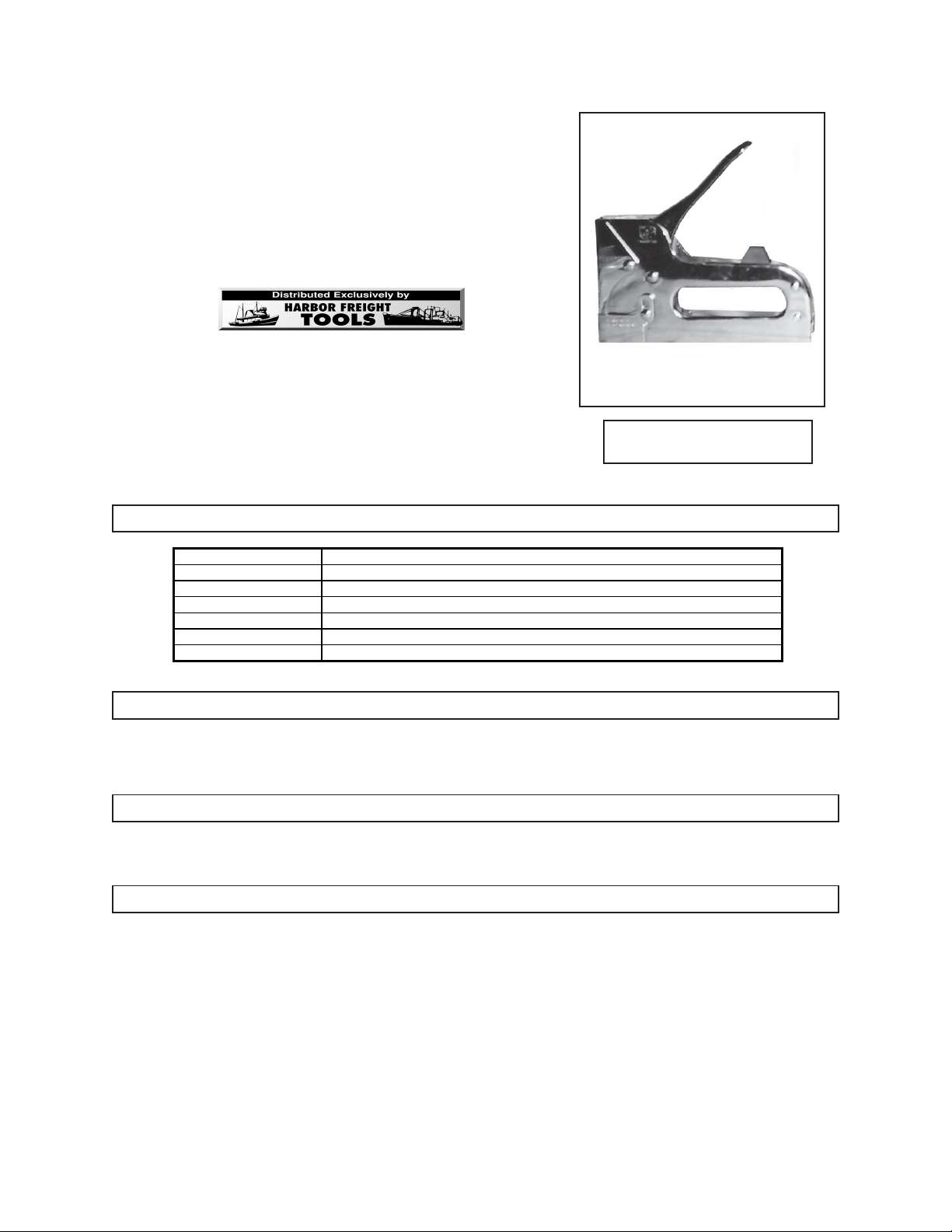
HEAVY DUTY
TACKING GUN
(Model 93926)
ASSEMBLY AND OPERATING INSTRUCTIONS
3491 Mission Oaks Blvd., Camarillo, CA 93011
Visit our Web site at: http://www.harborfreight.com
All rights reserved. No portion of this instruction sheet or any artwork contained
Copyright 2006 by Harbor Freight Tools®.
herein may be reproduced in any shape or form without the express written consent of
For technical questions, please call 1-800-444-3353.
Item Description
Staple Size Capacity Accepts From 5/32” to 9/16” Long x 7/16” Wide x 3/64” Thick (18 Gauge) Staples
Magazine Type Spring Loaded, Slide-Strip Magazine
Magazine Capacity Accepts Up To 80 Staples
Trigger Actuation Type Palm-Push Trigger Lever
Overall Dimensions 7-1/4” Long x 1-1/2” Wide x 6-7/8” High
Net Weight 1.9 Lbs.
©
Harbor Freight Tools.
PRODUCT SPECIFICATIONS
Due to continuing improvements, actual product
may differ slightly from the product described herein.
TO PREVENT SERIOUS INJURY,
READ AND UNDERSTAND ALL WARNINGS
AND INSTRUCTIONS BEFORE USE.
SAVE THIS INSTRUCTION SHEET
You will need this instruction sheet for the safety warnings and precautions, assembly, operating, inspection, maintenance and
cleaning procedures, parts list and assembly diagram. Keep your invoice with this instruction sheet. Write the invoice number on the
front cover. Keep this instruction sheet and invoice in a safe and dry place for future reference.
UNPACKING
When unpacking, check to make sure that the product is intact and undamaged. If any parts are missing or broken, please call Harbor
Freight Tools at the number shown on the front of this instruction sheet as soon as possible.
SAFETY WARNINGS AND PRECAUTIONS
1. Keep work area clean. Cluttered areas invite injuries.
2. Keep children away. Children must never be allowed in the work area. Do not let them handle this product.
3. Store idle equipment. When not in use, tools must be stored in a dry location to inhibit rust. Always lock up tools and
keep out of reach of children.
4. Use the right tool for the job. Do not attempt to force a small tool or attachment to do the work of a larger industrial tool.
There are certain applications for which this tool was designed. It will do the job better and more safely at the rate for which
it was intended. Do not modify this tool, and do not use this tool for a purpose for which it was not intended.
5. Use eye protection. Always wear ANSI approved impact safety eye glasses under an ANSI approved full face shield.
6. Point the Tacking Gun away from yourself and others at all times and especially when opening the Magazine to
clear a jammed staple. As the Magazine is opened, the jammed staple may be shot out unexpectedly.
7. Place the staple exit point firmly against the work surface before firing. Staples fired “into the air” can cause serious
injury.
8. Use the proper size staple. This product accepts from 5/32” to 9/16” long x 7/16” wide x 3/64” (18 Ga.) staples only.
Page 2
9. WARNING! Avoid accidental electrical shock. Never staple into electrical wires, especially those which may be
hidden from view.
10. WARNING: Some dust created by power sanding, sawing, grinding, drilling, and other construction activities contain
chemicals known (to the State of California) to cause cancer, birth defects, or other reproductive harm. Some examples of
these chemicals are: Lead from lead-based paints, crystalline silica from bricks, cement, and other masonry products,
arsenic and chromium from chemically treated lumber.
(California Health & Safety Code 25249.5, et seq.)
11. WARNING: The warnings, cautions, and instructions discussed in this instruction manual cannot cover all possible
conditions and situations that may occur. It must be understood by the operator that common sense and caution are factors
which cannot be built into this product, but must be supplied by the operator.
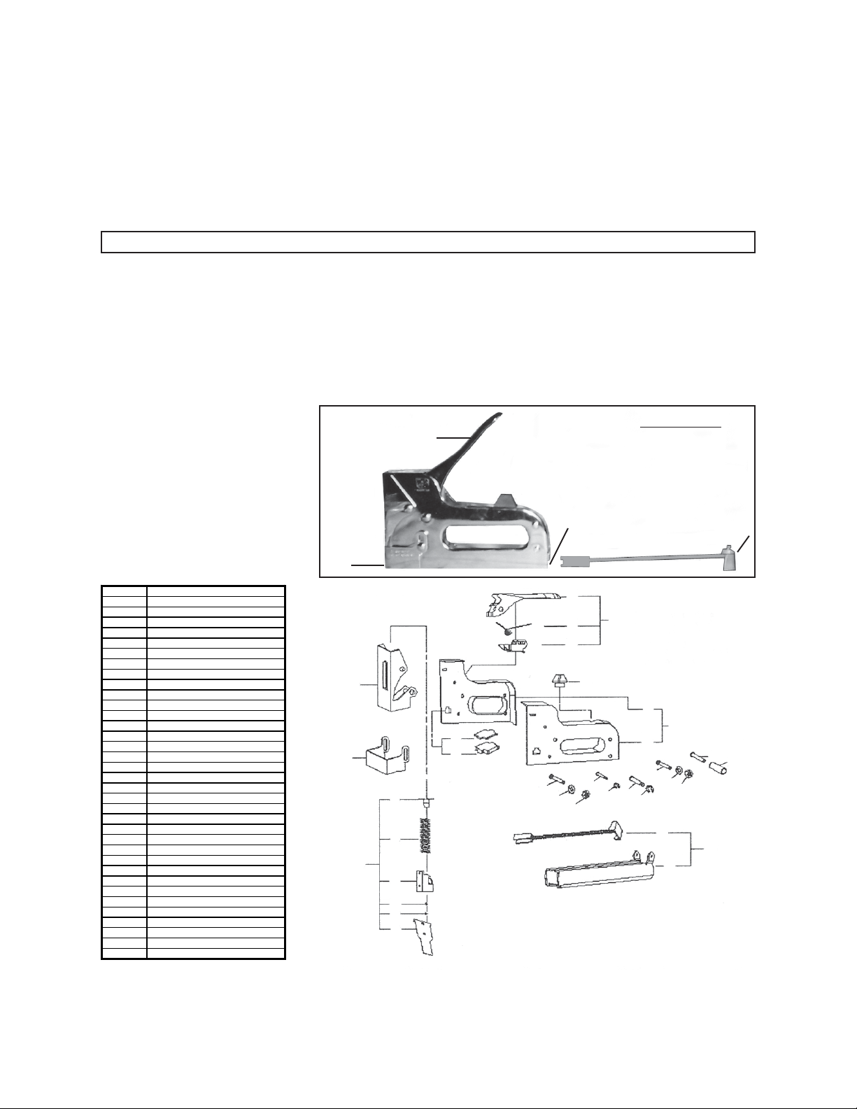
OPERATING INSTRUCTIONS
Note: When loading staples or when clearing jammed staples, always keep your hands off the Handle (10).
1. To load the Tacking Gun, push the Pusher (7) inward first. Then press downward and pull out the Pusher (7) assembly.
(See Figure A.)
2. Load a strip of Staples (35) into the Magazine (6). (See Figure A.)
3. Slide in the Pusher (7), and push it upward to lock it in place. (See Figure A.)
4. To use the Tacking Gun, position the nose of the tool against the work surface to which a Staple (35) is to be fired. Hold
the Tacking Gun firmly with both hands and squeeze the tool’s Handle (10). Repeat this procedure to finish the work.
(See Figure A.)
5. To clear jammed Staples (35), turn the Tacking Gun sideways so that the nose of the tool is pointing away from yourself and
others. Carefully remove the Pusher
(7) and remove all Staples from the
Magazine (6). If necessary, use
needle nose pliers to remove a bent
Staple from the nose of the tool. Then
reload the Magazine with up to 80
Staples, and re-install the Pusher.
(See Figure A.)
HANDLE (10)
FIGURE A
MAGAZINE (6)
NOSE
Pa rt # Description
1 Left Steel Panel
2 Right Steel Panel
3 Upper Cushion
4 Lower Cushion
5 Rubber Trigger Bump Stopper
6 Magazine
7 Pusher
8 Trigger
9 Trigger Lever
10 Handle
11 Trigger Assembly
12 Front Cover
13 Adjustable Cover
14 Cap Cover
15 Compression Spring
16 Spring Base
17 Step Pin
18 Step Pin
19 Driver Blade
20 Compression Set
21 O-Ring (12)
22 Screw (M5)
23 Magazine Assembly
24 Gun Body
25 Step Pin
26 Mini-Socket
27 Screw (M4)
28 O-Ring (9)
29 Screw (M4x27mm)
30 E-Ring (10)
31 Step Pin (6x28mm)
32 E-Ring (7)
33 Step Pin (4.35x28mm)
34 Screw (M5x33mm)
35 Staples (Qty. 400)
THE MANUFACTURER AND/OR DISTRIBUTOR HAS PROVIDED THE PARTS LIST AND ASSEMBLY DIAGRAM IN THIS MANUAL AS A REFERENCE TOOL ONLY. NEITHER THE
MANUFACTURER OR DISTRIBUTOR MAKES ANY REPRESENTATION OR WARRANTY OF ANY KIND TO THE BUYER THAT HE OR SHE IS QUALIFIED TO REPLACE ANY PARTS
OF THE PRODUCT. IN FACT, THE MANUFACTURER AND/OR DISTRIBUTOR EXPRESSLY STATES THAT ALL REPAIRS AND PARTS REPLACEMENTS SHOULD BE UNDERTAKEN BY CERTIFIED AND LICENSED TECHNICIANS, AND NOT BY THE BUYER. THE BUYER ASSUMES ALL RISKS AND LIABILITY ARISING OUT OF HIS OR HER REPAIRS
TO THE ORIGINAL PRODUCT OR REPLACEMENT PARTS THERETO, OR ARISING OUT OF HIS OR HER INSTALLATION OF REPLACEMENT PARTS THERETO.
12
3
13
14
15
20
16
17
18
19
4
Some parts are listed and shown for illustration purposes only,
and are not available individually as replacement parts.
10
11
9
8
5
1
2
29
34
33
22
32
NOTE:
21
28
31
30
7
PUSHER (7)
25
26
27
23
6
SKU 93926 For technical questions, please call 1-800-444-3353 PAGE 2
 Loading...