

Page 1
w/Aluminum Pole
Materials:
100% polyester, antique beige
colored fabric. UV treated, mildew resistant with eight ribs, 9
ft. long, and an aluminum pole
with a tilt mechanism that will
angle at a 45 degree angle, left
or right.
Visit our Web site at http://www.harborfreight.com
9’ UMBRELLA
93660
3491 Mission Oaks Blvd., Camarillo, CA 93011
Copyright © 2005 by Harbor Freight Tools®. All rights reserved. No portion of this manual or any artwork contained herein
may be reproduced in any shape or form without the express written consent of Harbor Freight Tools.
UNPACKING
When unpacking, check to make sure all parts shown on the back of this instruction sheet are included. If any parts are missing or
broken, please call Harbor Freight Tools at the number shown on the front of this sheet as soon as possible.
ASSEMBLY AND OPERATING INSTRUCTIONS
NOTE: All parts below refer to the parts listed on the reverse side of this instruction sheet.
1. Caution: DO NOT attempt to use this Umbrella in moderate or high wind conditions. Doing so may cause personal injury
and/or damage to the Umbrella and personal property. Be careful not to pinch fingers when opening and closing the Umbrella.
2. To assemble, insert Lower Pole (8) with its threaded end upward, securely into a
NOTE: This Umbrella is intended for use only with a heavy duty umbrella stand which is not provided with this product.
Adjustable, heavy duty umbrella stands are sold separately by special order from Harbor Freight Tools (SKU 94041).
3. Screw the Connector/Crank (7) onto the threaded end of the Lower Pole.
4. Screw the Upper Pole (6), with its pre-attached upper umbrella assembly, securely into the top of the Connector/Crank.
5. Hand crank the Connector/Crank
above the self-locking Safety Lock (10), thereby locking the upper umbrella
assembly into place.
6. If you wish to tilt the upper part of the umbrella for shade, press the “push
button”. It will tilt to a 45 degree angle. To straighten up, reverse the tilt until the
tilt mechanism “clicks” into place for safety. Note: When tilting, opening, or
closing the umbrella, watch your head for injuries.
7. When finished using the Umbrella, crank the Connector/Crank
until the upper umbrella assembly is completely closed.
CLEANING AND MAINTENANCE
The Umbrella is now ready for use.
clockwise
in order to raise the Hub/Runner (5)
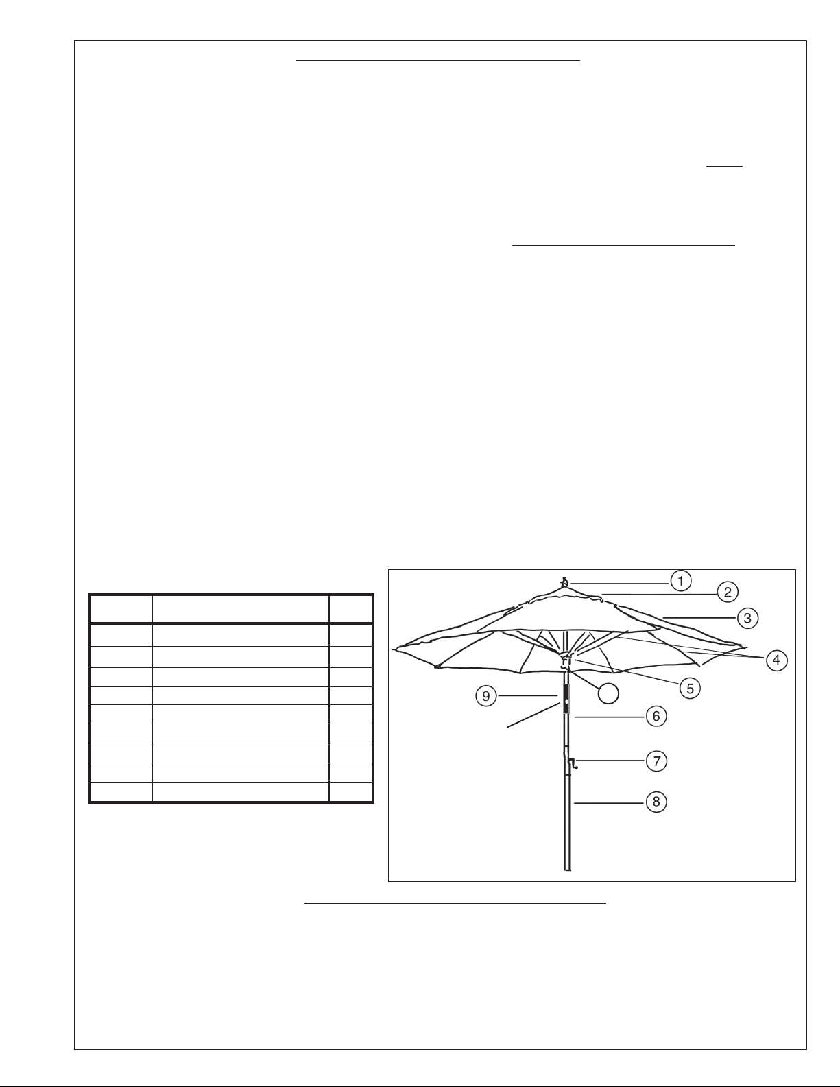
See Figure 1.
counterclockwise
heavy duty
Hub/Runner (5)
Push Button (9)
umbrella stand.
Figure 1
1. To clean, fully open the Umbrella. Wipe with a clean, damp cloth, using a mild soap with water if necessary.
2. Periodically, lightly lubricate all moving parts.
SEE REVERSE SIDE OF THIS INSTRUCTION SHEET FOR PRODUCT WARNINGS,
PRECAUTIONS, PARTS LIST, AND ASSEMBLY DIAGRAM.
Page 2
SAFETY WARNINGS AND PRECAUTIONS
1. KEEP PRODUCT USAGE AREA CLEAN.
Cluttered areas invite injuries.
2. KEEP CHILDREN AWAY FROM PRODUCT USAGE
AREA. Do not allow children to handle this product.
3. DO NOT SET UP THIS PRODUCT IF UNDER THE
INFLUENCE OF ALCOHOL OR DRUGS. Read
warning labels on prescriptions to determine if your
judgement or reflexes are impaired while taking drugs.
If there is any doubt, do not attempt to use this product.
4. USE EYE PROTECTION DURING ASSEMBLY.
Wear ANSI approved safety impact eye goggles. The
ANSI approved safety impact goggles are available from
Harbor Freight Tools.
5. DO NOT ATTEMPT TO ASSEMBLE OR USE THIS
PRODUCT IN MODERATE OR HEAVY WIND CONDITIONS. Doing so may cause personal injury and/or
damage to the umbrella
and personal property.
6. CHECK FOR DAMAGED PARTS. Before using this
product, carefully check that it will operate properly and
perform its intended function. Check for damaged parts
and any other conditions that may affect its operation.
Replace or repair damaged or worn parts immediately.
7. MAINTENANCE: Service and maintenance should
be performed regularly by a qualified technician.
8. USE THE RIGHT PRODUCT FOR THE RIGHT
JOB. There are certain applications for which this
product was designed. Use this product
ONLY with
a heavy duty stand, weighing at least 18 Lbs., and
capable of firmly securing this umbrella. Do not use
this product in a way for which it is not intended.
SAVE THIS INSTRUCTION FLYER
You will need this instruction flyer for the Operating
and Maintenance Procedures, Safety Warnings and
Precautions, Parts List and Assembly Diagram. Keep
your invoice with this instruction flyer. Write the invoice
number on the front of this flyer. Keep this
instruction flyer and invoice in a safe and dry place
for future reference.
NOTE: Some parts are listed and shown for illustration
purposes only, and are not available individually as
replacement parts.
PARTS LIST / ASSEMBLY DIAGRAM
PART # DESCRIPTION QTY
Top Finial
1
Air Vent
2
Cover
3
Rib
4
Hub/Runner
5
Upper Pole
6
Connector/Crank
7
Lower Poll
8
Tilt Mechanism
9
THE MANUFACTURER AND/OR DISTRIBUTOR HAS PROVIDED THE PARTS DIAGRAM IN THIS MANUAL AS A REFERENCE
ONLY. NEITHER THE MANUFACTURER NOR DISTRIBUTOR MAKES ANY REPRESENTATION OR WARRANTY OF ANY KIND
TO THE BUYER THAT HE OR SHE IS QUALIFIED TO MAKE ANY REPAIRS TO THE PRODUCT OR THAT HE OR SHE IS QUALIFIED TO REPLACE ANY PARTS OF THE PRODUCT. IN FACT, THE MANUFACTURER AND/OR DISTRIBUTOR EXPRESSLY
STATES THAT ALL REPAIRS AND PARTS REPLACEMENTS SHOULD BE UNDERTAKEN
CIANS AND NOT BY THE BUYER. THE BUYER ASSUMES ALL RISK AND LIABILITY
THE ORIGINAL PRODUCT OR REPLACEMENT PARTS THERETO, OR ARISING OUT OF HIS OR HER INSTALLATION OF REPLACEMENT PARTS THERETO.
w/ Push Button
1
1
1
8
1
1
1
1
1
Push Button (9)
PLEASE READ THE FOLLOWING CAREFULLY
BY CERTIFIED AND LICENSED TECHNI-
ARISING OUT OF HIS OR HER REPAIRS TO
10
TOOL
 Loading...