

Page 1

Torque Multiplier/
®
Lugnut Remover
93645
Safety Precautions and Instructions
TO PREVENT SERIOUS INJURY,
READ AND UNDERSTAND ALL WARNINGS AND INSTRUCTIONS BEFORE USE.
3491 Mission Oaks Blvd./Camarillo, CA 93011
Copyright© 2005 by Harbor Freight Tools®. All rights reserved. No portion of this instruction sheet or any artwork
contained herein may be reproduced in any shape or form without the express written consent of Harbor Freight Tools.
For technical questions, please call 1-800-444-3353.
General Safety Rules
1. Always wear ANSI approved safety goggles
during use.
2. Do not force the tool. Use the correct tool for
your application. The correct tool will do the job
better and safer at the rate for which it is designed.
Do not force the tool and do not use the tool for a
purpose for which it is not intended. This tool is
designed explicitly to help remove or tighten
Lugnuts. It should not be used for any other purpose,
because improper mounting could result in the unit
coming loose under load, causing severe personal
injury or property damage.
3. Verify that the socket and the support completely
and securely fit over both lugnuts before use.
4. After this tool is used, a torque wrench (not
included) must also be used to verify that the
lugnuts are properly tightened in place.
5. DO NOT OVERTIGHTEN. NEVER use this tool to
tighten a nut/bolt above its torque specification.
6. Before every use, check for any broken parts or
mounting fixtures, and any other condition that
may affect proper operation. Any part that appears
damaged should be carefully checked to determine
that it will operate properly and perform its intended
function. Do not use if any socket is worn, cracked,
or chipped.
7. Stay alert. Watch what you are doing, use common
sense. Do not use this tool if you are tired.
8. Do not use this tool if under the influence of
alcohol or drugs. Read warning labels if taking
prescription medicine to determine if your judgment
or reflexes are impaired while taking drugs. If there
is any doubt, do not use this tool.
9. Replacement parts and accessories. When
servicing, use only identical replacement parts. Use
of any other parts is dangerous and will void the
warranty. Only use accessories intended for use with
this tool. DO NOT USE ANY DIFFERENT
HANDLES OR SOCKETS WITH THIS TOOL;
sockets/handles not designed for this tool may
break or cause the unit to become unstable,
causing personal injury or property damage.
10. This unit may cause some cosmetic damage to
the rim during normal use.
11. Keep bystanders, children, and visitors away
while operating a power tool. Distractions can
cause you to lose control. Protect others in the work
area from debris such as chips and sparks. Provide
barriers or shields as needed.
The warnings, cautions, and instructions
discussed in this instruction sheet cannot cover
all possible conditions and situations that may
occur. It must be understood by the operator
that common sense and caution are factors
which cannot be built into this set, but must be
supplied by the operator.
SAVE THIS INSTRUCTION SHEET. (Operation on Back.)
Page 2
PLEASE READ THE FOLLOWING CAREFULLY
THE MANUFACTURER AND/OR DISTRIBUTOR HAS
PROVIDED THE PARTS DIAGRAM IN THIS MANUAL
AS A REFERENCE TOOL ONLY. NEITHER THE
MANUFACTURER NOR DISTRIBUTOR MAKES ANY
REPRESENTATION OR WARRANTY OF ANY KIND TO
THE BUYER THAT HE OR SHE IS QUALIFIED TO
MAKE ANY REPAIRS TO THE PRODUCT OR THAT
HE OR SHE IS QUALIFIED TO REPLACE ANY PARTS
OF THE PRODUCT. IN FACT, THE MANUFACTURER
AND/OR DISTRIBUTOR EXPRESSLY STATES THAT
ALL REPAIRS AND PARTS REPLACEMENTS
SHOULD BE UNDERTAKEN BY CERTIFIED AND LICENSED TECHNICIANS AND NOT BY THE BUYER.
THE BUYER ASSUMES ALL RISK AND LIABILITY
ARISING OUT OF HIS OR HER REPAIRS TO THE
ORIGINAL PRODUCT OR REPLACEMENT PARTS
THERETO, OR ARISING OUT OF HIS OR HER IN-
STALLATION OF REPLACEMENT PARTS THERETO.
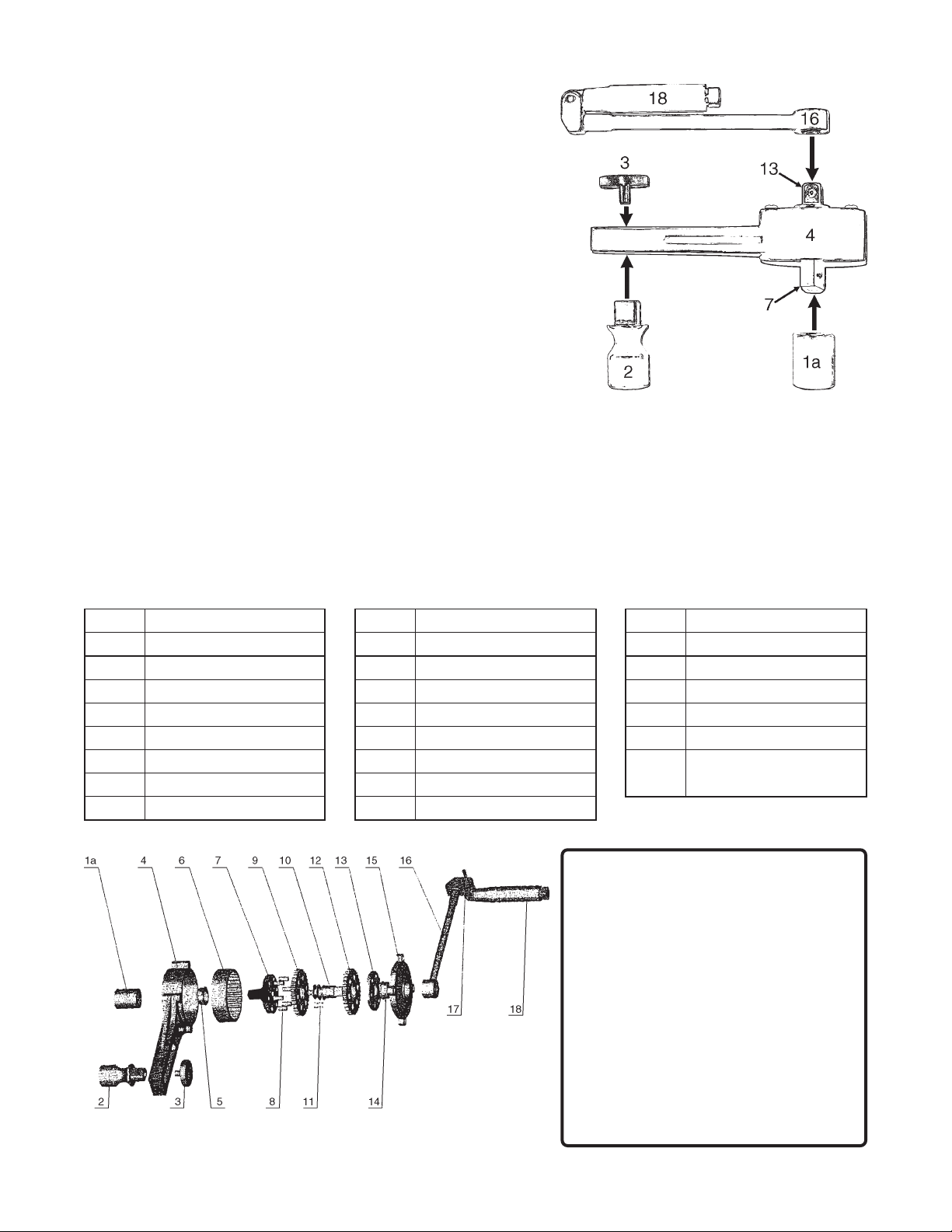
Operation
(Refer to the diagram to the right and the picture on the front.)
1. Attach the chosen Socket (1a-1d) to the Output Driver (7).
Note: The Output Driver (7) is on the side of the Housing (4)
that has no screw heads visible.
2. Attach the Support Socket and Knob (2,3) through the slot in the
housing, with the Support Socket (2) on the same side as the
Socket (1a). Leave the Knob (3) loose.
3. Raise the vehicle, support the vehicle on jackstands (not included),
engage the parking brake, and place wheel chocks (not included)
on any wheels contacting the ground. Place the Socket (1a) over
the Lugnut that will be tightened or loosened and place the Support
Socket (2) over another Lugnut on the same rim. The Socket
may need to be repositioned and/or the Input Driver (13) may
need to be turned to get both sockets securely in place. Tighten
the Support Knob (3).
WARNING: Make certain that both Sockets are securely in
place over the Lugnuts.
4. Place the Handle Shaft (16) over the Input Driver (13) unfold the Handle (18) and turn it in the direction noted on
the Gearbox Cover (15). NOTE: This will be the opposite of the normal tightening/loosening direction.
The Handle (18) should move relatively easily - if it does not, the unit may be assembled backwards, check step
one above to ensure that the Socket is on the Output Driver (7). Keep in mind that the socket will move slowly,
this is by design.
5. When tightening, finger tighten the lugnut first. Keep in mind that this device allows you to apply much more
torque than you ordinarily could. Use care not to overtighten lugnuts.
6. After use, disassemble, clean, and store in Carrying Case (19).
traPnoitpircseDtraPnoitpircseDtraPnoitpircseD
a1tekcoSmm916raeGsulunnAretuO41gniraeB
b1tekcoS"4/37revirDtuptuO51revoCx
c1tekcoS"61/318niP61tfahSeldnaH
d1tekcoS"8/79raeGsulunnArennI71niPeldnaH
2tekcoStroppuS01gnihsuBcirtneccE81eldna
3bonKtroppuS11niP
4gnisuoH21raeGsulunnArennI
5gniraeB31revirDtupnI
Assembly Diagram
NOTE: Some parts are listed and shown for illustration purposes only
and are not available individually as replacement parts.
Parts List
obraeG
H
91
esaCgniyrraC
)nwohStoN(
ITEM 93645
 Loading...