

Page 1
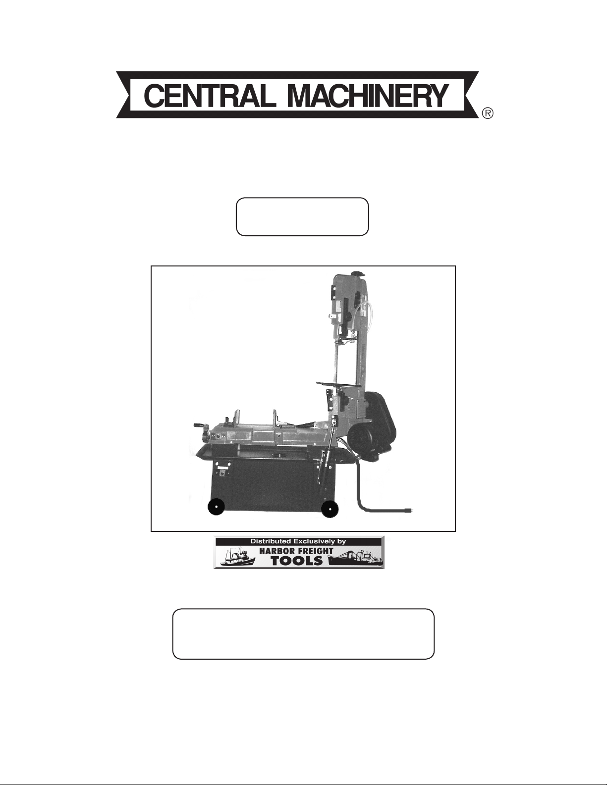
7” X 12”
®
METAL CUTTING BANDSAW
Model 93507
ASSEMBLY AND OPERATING INSTRUCTIONS
Due to continuing improvements, actual product may differ slightly from the product described herein.
3491 Mission Oaks Blvd., Camarillo, CA 93011
Visit our Web site at: http://www.harborfreight.com
TO PREVENT SERIOUS INJURY,
READ AND UNDERSTAND ALL WARNINGS
AND INSTRUCTIONS BEFORE USE.
Copyright© 2005 by Harbor Freight Tools®. All right reserved. No portion of this manual or
any artwork contained herein may be reproduced in any shape or form without the express
written consent of Harbor Freight Tools.
For technical questions, please call 1-800-444-3353.
Page 2

Contents
PRODUCT SPECIFICATIONS .....................................................................3
GENERAL SAFETY RULES ........................................................................3
SPECIFIC SAFETY RULES .........................................................................6
GROUNDING ...............................................................................................8
UNPACKING ..............................................................................................11
ASSEMBLY INSTRUCTIONS ....................................................................11
A - ATTACH THE WHEELS ......................................................................................11
B - REMOVE THE SHIPPING BOLT ........................................................................12
C - ATTACH THE PULLEY COVER ..........................................................................12
D - ATTACH THE TOOL STOP ROD AND BLOCK ..................................................13
E - INSTALL THE COOLANT TANK .........................................................................13
WIRING INSTRUCTIONS .........................................................................................14
OPERATING INSTRUCTIONS ...................................................................15
SELECTING PROPER BLADE SPEEDS: ...............................................................15
USING THE QUICK VISE: ........................................................................................15
ADJUSTING THE QUICK VISE FOR AN ANGLE CUT: ..........................................16
ADJUSTING THE STOP BLOCK: ............................................................................16
CONVERTING THE BANDSAW FOR VERTICAL USE: ..........................................17
ADJUSTING THE BLADE GUIDE BEARINGS: ....................................................... 17
ADJUSTING THE BLADE TRACKING: ....................................................................18
ADJUSTING THE BLADE TENSION: ......................................................................19
ADJUSTING THE FEED RATE: ...............................................................................19
ADJUSTING THE BLADE GUIDE BRACKETS: ......................................................20
BASIC BANDSAW OPERATION -- VERTICAL POSITION: ....................................20
BASIC BANDSAW OPERATION -- HORIZONTAL POSITION: ...............................22
INSPECTION, MAINTENANCE, AND CLEANING ....................................24
TROUBLESHOOTING ...............................................................................29
PARTS LIST ...............................................................................................30
ASSEMBLY DIAGRAM ..............................................................................32
SKU 93507 For technical questions, please call 1-800-444-3353. Page 2
Page 3

PRODUCT SPECIFICATIONS
Electrical Requirements 120/230 VAC (Dual voltage capability)
Cutting Capacity 7” (Round Stock) 7” x 12” (Flat/Square Stock)
Blade Speeds (FPM) 260 / 178 / 132 / 86
Required Blade Size ¾” Wide x .032” Thick x 93” Long (Included)
Required V-Belt Size 3V-270 (Included)
Vise Capacity/Miter Angles 10-1/2” / 0-45 Degrees in 1 Degree Increments (Right Only)
Throat Depth 9-5/8”
Coolant Pump 120 VAC / 60 Hz / 0.6 Amps
Coolant Tank Capacity 9 Quarts
Overall Dimensions 15-1/2” Long x 46-1/2” Wide x 62-7/8” High
Net Weight 312 Pounds
Motor Type: 1 HP /Single Phase
60 Hz / 1720 RPM
9 Amps @ 120 Volt
4.5 Amps @ 230 Volt
Power Cord Type & Length Provided: 120 volt / 6’4” Long
Power Cord Plug Type Provided: 120 volt, 3-Prong
Overload Equipped: Resettable Circuit Breaker
SAVE THIS MANUAL
You will need this manual for the safety warnings and precautions, assembly, operating, inspection, maintenance and cleaning procedures, parts list and assembly diagram.
Keep your invoice with this manual. Write the invoice number on the inside of the front
cover. Keep this manual and invoice in a safe and dry place for future reference.
1.
2.
3.
GENERAL SAFETY RULES
WARNING!
READ AND UNDERSTAND ALL INSTRUCTIONS
Failure to follow all instructions listed below may result in
electric shock, fire, and/or serious injury.
SAVE THESE INSTRUCTIONS
WORK AREA
Keep your work area clean and well lit. Cluttered benches and dark areas invite
accidents.
Do not operate power tools in explosive atmospheres, such as in the pres-
ence of flammable liquids, gases, or dust. Power tools create sparks which may
ignite the dust or fumes.
Keep bystanders, children, and visitors away while operating a power tool.
Distractions can cause you to lose control. Protect others in the work area from
debris such as chips and sparks. Provide barriers or shields as needed.
SKU 93507 For technical questions, please call 1-800-444-3353. Page 3
Page 4

ELECTRICAL SAFETY
1.
2.
3.
4.
5.
Grounded tools must be plugged into an outlet properly installed and grounded
in accordance with all codes and ordinances. Never remove the grounding
prong or modify the plug in any way. Do not use any adapter plugs. Check with
a qualified electrician if you are in doubt as to whether the outlet is properly
grounded. If the tools should electrically malfunction or break down, grounding
provides a low resistance path to carry electricity away from the user.
Double insulated tools are equipped with a polarized plug (one blade is wider
than the other). This plug will fit in a polarized outlet only one way. If the plug
does not fit fully in the outlet, reverse the plug. If it still does not fit, contact
a qualified electrician to install a polarized outlet. Do not change the plug
in any way. Double insulation eliminates the need for the three wire grounded
power cord and grounded power supply system.
Avoid body contact with grounded surfaces such as pipes, radiators, ranges,
and refrigerators. There is an increased risk of electric shock if your body is
grounded.
Do not expose power tools to rain or wet conditions. Water entering a power
tool will increase the risk of electric shock.
Do not abuse the Power Cord. Never use the Power Cord to carry the tools or
pull the Plug from an outlet. Keep the Power Cord away from heat, oil, sharp
edges, or moving parts. Replace damaged Power Cords immediately. Dam-
aged Power Cords increase the risk of electric shock.
6.
1.
2.
3.
When operating a power tool outside, use an outdoor extension cord marked
“W-A” or “W”. These extension cords are rated for outdoor use, and reduce the
risk of electric shock.
PERSONAL SAFETY
Stay alert. Watch what you are doing, and use common sense when operat-
ing a power tool. Do not use a power tool while tired or under the influence
of drugs, alcohol, or medication. A moment of inattention while operating power
tools may result in serious personal injury.
Dress properly. Do not wear loose clothing or jewelry. Contain long
hair. Keep your hair, clothing, and gloves away from moving parts.
Loose clothes, jewelry, or long hair can be caught in moving parts.
Avoid accidental starting. Be sure the Power Switch is off before plugging
in. Carrying power tools with your finger on the Power Switch, or plugging in power
tools with the Power Switch on, invites accidents.
SKU 93507 For technical questions, please call 1-800-444-3353. Page 4
Page 5

4.
Remove adjusting keys or wrenches before turning the power tool on. A
wrench or a key that is left attached to a rotating part of the power tool may result
in personal injury.
5.
6.
1.
2.
3.
4.
Do not overreach. Keep proper footing and balance at all times. Proper footing
and balance enables better control of the power tool in unexpected situations.
Use safety equipment. Always wear eye protection. Dust mask, nonskid safety
shoes, hard hat, or hearing protection must be used for appropriate conditions.
TOOL USE AND CARE
Use clamps (not included) or other practical ways to secure and support the
workpiece to a stable platform. Holding the work by hand or against your body
is unstable and may lead to loss of control.
Do not force the tool. Use the correct tool for your application. The correct
tool will do the job better and safer at the rate for which it is designed.
Do not use the power tool if the Power Switch does not turn it on or off. Any
tool that cannot be controlled with the Power Switch is dangerous and must be
replaced.
Disconnect the Power Cord Plug from the power source before making any
adjustments, changing accessories, or storing the tool. Such preventive safety
measures reduce the risk of starting the tool accidentally.
5.
6.
7.
8.
1.
2.
Store idle tools out of reach of children and other untrained persons. Tools
are dangerous in the hands of untrained users.
Maintain tools with care. Keep cutting tools sharp and clean. Properly main-
tained tools with a sharp cutting edge are less likely to bind and are easier to control.
Do not use a damaged tool. Tag damaged tools “Do not use” until repaired.
Check for misalignment or binding of moving parts, breakage of parts, and any
other condition that may affect the tool’s operation. If damaged, have the tool
serviced before using. Many accidents are caused by poorly maintained tools.
Use only accessories that are recommended by the manufacturer for your
model. Accessories that may be suitable for one tool may become hazardous
when used on another tool.
SERVICE
Tool service must be performed only by qualified repair personnel. Service or
maintenance performed by unqualified personnel could result in a risk of injury.
When servicing a tool, use only identical replacement parts. Follow instruc-
tions in the “Inspection, Maintenance, And Cleaning” section of this manual.
SKU 93507 For technical questions, please call 1-800-444-3353. Page 5
Page 6

Use of unauthorized parts or failure to follow maintenance instructions may create
a risk of electric shock or injury.
SPECIFIC SAFETY RULES
1.
2.
3.
4.
5.
6.
Maintain labels and nameplates on the Bandsaw. These carry important infor-
mation. If unreadable or missing, contact Harbor Freight Tools for a replacement.
Always wear safety impact eye goggles and heavy work gloves
when using the Bandsaw. Using personal safety devices reduce the
risk for injury. Safety impact eye goggles and heavy work gloves are
available from Harbor Freight Tools. Heavy work boots, along with
other work clothing, are also recommended during use.
Maintain a safe working environment. Keep the work area well lit. Make sure
there is adequate surrounding workspace. Always keep the work area free of ob-
structions, grease, oil, trash, and other debris. Do not use a power tool in areas
near flammable chemicals, dusts, and vapors. Do not use this product in a damp
or wet location.
Avoid unintentional starting. Make sure you are prepared to begin work before
turning on the Bandsaw.
Do not force the Bandsaw. This tool will do the work better and safer at the
speed and capacity for which it was designed. Do not force the Saw Blade into the
workpiece being cut.
WARNING! Keep hands and fingers away from cutting area and Saw Blade.
7.
8.
9.
10.
11.
12.
13.
SKU 93507 For technical questions, please call 1-800-444-3353. Page 6
Never leave the Bandsaw unattended when it is plugged into an electrical
outlet. Turn off the tool, and unplug it from its electrical outlet before leaving.
Make sure the Bandsaw is located on a flat, level, sturdy surface capable of
supporting the weight of the Saw and workpieces. Always “chock” the Wheels
to prevent the Bandsaw from accidentally moving.
Make sure the Table of the Bandsaw and surrounding area are clear with the
exception of the workpiece to be cut.
Before using the Bandsaw, check to make sure the Saw Blade is properly
mounted and is not cracked or bent.
Industrial applications must follow OSHA guidelines.
Never stand on the Bandsaw. Serious injury could result if the Bandsaw is tipped
or if the rotating Saw Blade is accidently contacted.
Never attempt to cut more than one workpiece at a time.
Page 7

14.
Never attempt to cut freehand. Make sure the workpiece to be cut is pressed
firmly against the Table and/or secured in the Vise.
15.
16.
17.
18.
19.
20.
21.
22.
When cutting a large workpiece, make sure its entire length is properly sup-
ported. If necessary, use a roller stand (not included).
Do not lean on the Bandsaw when the tool is in its upright position.
When moving the Bandsaw, always have its Head lowered to its horizontal
position.
Allow the Saw Blade to rotate to full speed before feeding a workpiece into
the Blade. When turning off the Bandsaw, allow the Saw Blade to spin down and
stop on its own. Do not press against the Saw Blade to stop it.
To avoid accidental injury, always wear heavy duty work gloves when chang-
ing the Saw Blade.
The Saw Blade will become hot while cutting. Allow the Saw Blade to completely
cool before handling.
Do not force the workpiece into the Saw Blade when cutting. Apply moderate
pressure, allowing the Saw Blade to cut without being forced.
Turn off the Bandsaw and allow the Saw Blade to completely stop if the Saw
Blade is to be backed out of an uncompleted cut.
23.
24.
25.
26.
27.
28.
29.
Never attempt to remove material stuck in the moving parts of the Bandsaw
while it is plugged in and running.
Make sure the workpiece to be cut off has sufficient room to move sideways.
Failure to do so may result in offcut binding against the Saw Blade.
Always unplug the Bandsaw from its electrical outlet before performing any
inspection, maintenance, or cleaning procedures.
Keep this product and all other tools and equipment away from children and
animals. Do not allow spectators in the work area.
Keep all safety guards in place and in proper working order.
This Bandsaw is designed for indoor use only.
WARNING! Some dust created by power sanding, sawing, grinding, drilling,
and other construction activities, contain chemicals known (to the State of Califor-
nia) to cause cancer, birth defects or other reproductive harm. Some examples of
these chemicals are: lead from lead-based paints, crystalline silica from bricks and
cement or other masonry products, arsenic and chromium from chemically treated
lumber. Your risk from these exposures varies, depending on how often you do this
type of work. To reduce your exposure to these chemicals: work in a well ventilated
SKU 93507 For technical questions, please call 1-800-444-3353. Page 7
Page 8

area, and work with approved safety equipment, such as those dust masks that
are specially designed to filter out microscopic particles. (California Health & Safety
Code § 25249.5, et seq.)
30.
31.
WARNING! People with pacemakers should consult their physician(s) before
using this product. Operation of electrical equipment in close proximity to a heart
pacemaker could cause interference or failure of the pacemaker.
WARNING! The warnings and cautions discussed in this manual cannot cover
all possible conditions and situations that may occur. It must be understood by the
operator that common sense and caution are factors which cannot be built into this
product, but must be supplied by the operator.
SAVE THESE INSTRUCTIONS
GROUNDING
WARNING!
Improperly connecting the grounding wire can result in the risk of electric shock.
Check with a qualified electrician if you are in doubt as to whether the outlet is
properly grounded. Do not modify the power cord plug provided with the tool.
Never remove the grounding prong from the plug. Do not use the tool if the
power cord or plug is damaged. If damaged, have it repaired by a service facility before use. If the plug will not fit the outlet, have a proper outlet installed by
a qualified electrician.
GROUNDED TOOLS: TOOLS WITH THREE PRONG PLUGS
1.
2.
SKU 93507 For technical questions, please call 1-800-444-3353. Page 8
Tools marked with “Grounding Required” have a three wire cord and three prong
grounding plug. The plug must be connected to a properly grounded outlet. If
the tool should electrically malfunction or break down, grounding provides a low
resistance path to carry electricity away from the user, reducing the risk of electric
shock. (See Figure A.)
The grounding prong in the plug is connected through the green wire inside the
cord to the grounding system in the tool. The green wire in the cord must be the
only wire connected to the tool’s grounding system and must never be attached to
an electrically “live” terminal. (See Figure A.)
Page 9
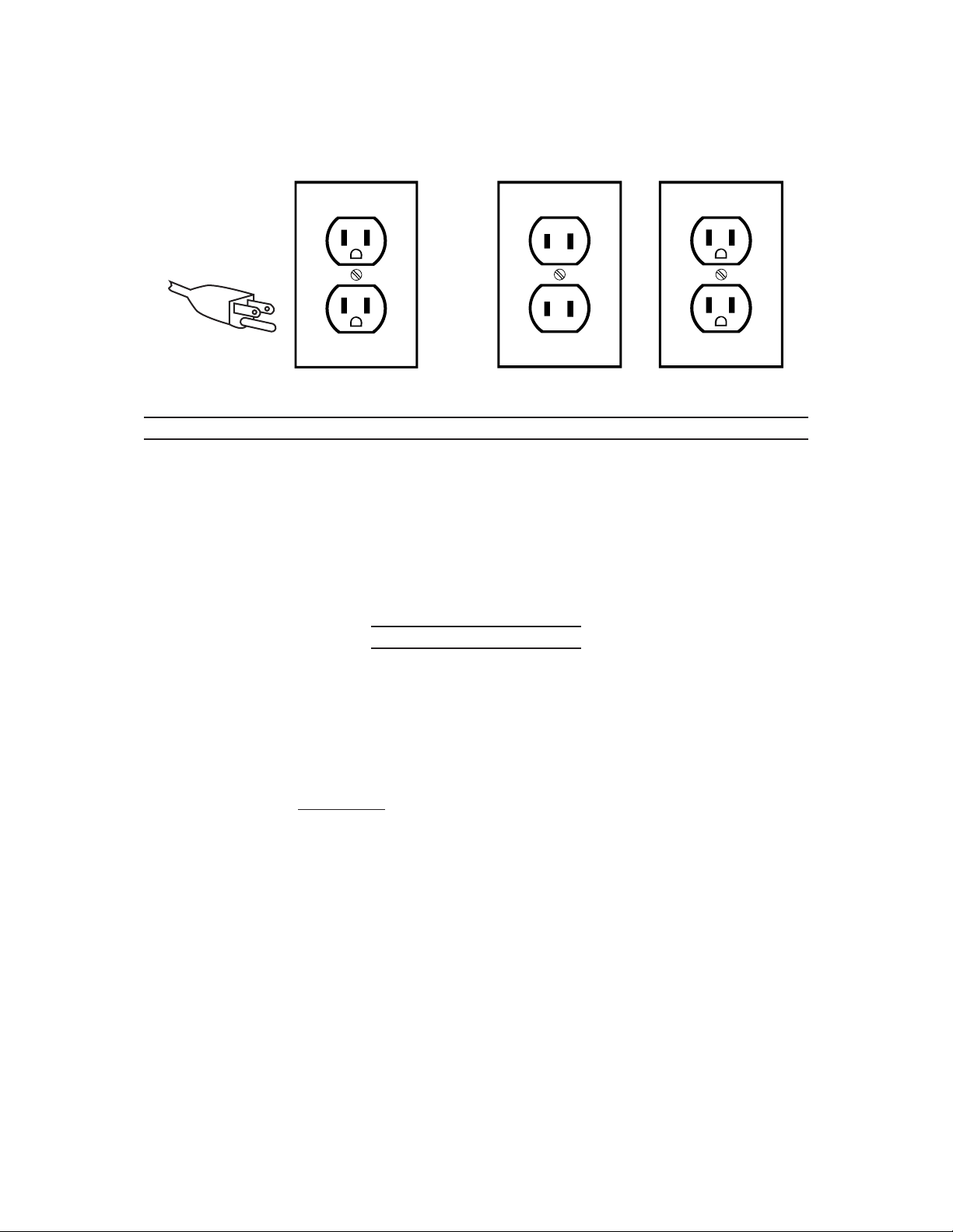
3.
Your tool must be plugged into an appropriate outlet, properly installed and grounded
in accordance with all codes and ordinances. The plug and outlet should look like
those in the following illustration. (See Figure A.)
THIS PRODUCT
USES A
3-PRONG PLUG
FIGURE A
FIGURE B
DOUBLE INSULATED TOOLS: TOOLS WITH TWO PRONG PLUGS
1.
2.
Tools marked “Double Insulated” do not require grounding. They have a special
double insulation system which satisfies OSHA requirements and complies with
the applicable standards of Underwriters Laboratories, Inc., the Canadian Standard
Association, and the National Electrical Code. (See Figure B.)
Double insulated tools may be used in either of the 120 volt outlets shown in the
preceding illustration. (See Figure B.)
EXTENSION CORDS
1.
2.
Grounded tools require a three wire extension cord. Double Insulated tools can
use either a two or three wire extension cord.
As the distance from the supply outlet increases, you must use a heavier gauge
extension cord. Using extension cords with inadequately sized wire causes a serious drop in voltage, resulting in loss of power and possible tool damage.
(See Figure C, next page.)
3.
The smaller the gauge number of the wire, the greater the capacity of the cord. For
example, a 14 gauge cord can carry a higher current than a 16 gauge cord.
(See Figure C.)
4.
When using more than one extension cord to make up the total length, make sure
each cord contains at least the minimum wire size required. (See Figure C.)
5.
If you are using one extension cord for more than one tool, add the nameplate am-
peres and use the sum to determine the required minimum cord size.
(See Figure C.)
6.
If you are using an extension cord outdoors, make sure it is marked with the suffix
“W-A” (“W” in Canada) to indicate it is acceptable for outdoor use.
SKU 93507 For technical questions, please call 1-800-444-3353. Page 9
Page 10
7.
Make sure your extension cord is properly wired and in good electrical condition.
Always replace a damaged extension cord or have it repaired by a qualified electrician before using it.
8.
Protect your extension cords from sharp objects, excessive heat, and damp or wet
areas.
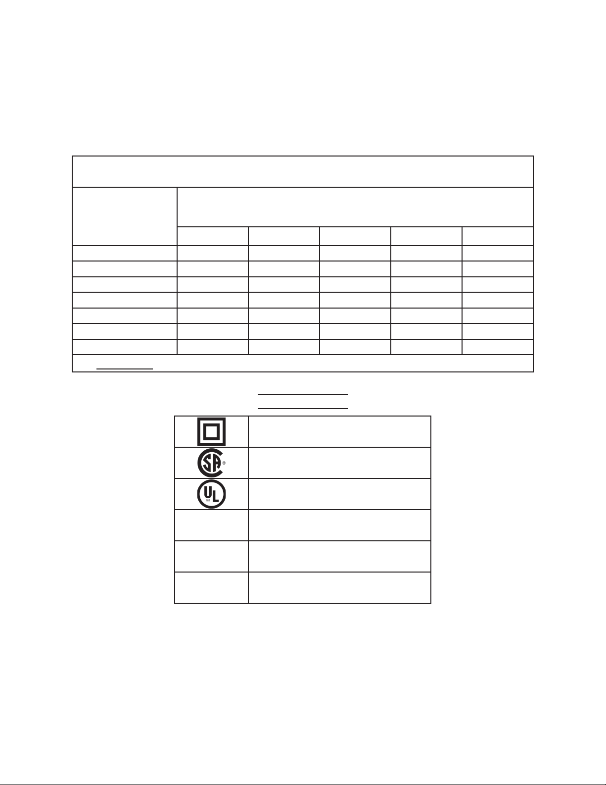
RECOMMENDED MINIMUM WIRE GAUGE FOR EXTENSION CORDS*
(120 OR 240 VOLT)
NAMEPLATE
EXTENSION CORD LENGTH
AMPERES
(at full load)
0 – 2.0 18 18 18 18 16
2.1 – 3.4 18 18 18 16 14
3.5 – 5.0 18 18 16 14 12
5.1 – 7.0 18 16 14 12 12
7.1 – 12.0 18 14 12 10 -
12.1 – 16.0 14 12 10 - -
16.1 – 20.0 12 10 - - -
FIGURE C
25 Feet 50 Feet 75 Feet 100 Feet 150 Feet
* Based on limiting the line voltage drop to five volts at 150% of the rated amperes.
SYMBOLOGY
V~
A
n0 xxxx/min.
Double Insulated
Canadian Standards Association
Underwriters Laboratories, Inc.
Volts Alternating Current
Amperes
No Load Revolutions per Minute (RPM)
SKU 93507 For technical questions, please call 1-800-444-3353. Page 10
Page 11

UNPACKING
When unpacking, check to make sure that the item is intact and undamaged. If any parts
are missing or broken, please call Harbor Freight Tools at the number shown on the cover
of this manual as soon as possible.
1. NOTE: For this procedure, you will need the assistance of additional personnel
and an adequate lifting device (not included).
2. Remove the box surrounding the Bandsaw using appropriate tools, being careful
not to injure yourself from sharp fasteners.
3. Search for and remove all bolts securing the Bandsaw to the pallet.
WARNING: At this point the Bandsaw could easily tip, causing serious injury. Have assistants stabilize the bandsaw.
4. Use the lifting device to lift the Bandsaw off the pallet and set it on a flat location
on the floor that is capable of properly supporting its weight.
ASSEMBLY INSTRUCTIONS
NOTE:
For additional information regarding the parts listed in the following
pages, refer to the Assembly Diagrams on pages 32 and 33.
WARNING! Always make sure the Toggle Switch (11) for the Bandsaw and
the Toggle Switch (37) for the Coolant Pump are both in their “OFF” position and
the tool is unplugged from its electrical outlet prior to assembling the tool, adding
any accessories, or making adjustments to the tool.
A - Attach The Wheels
Note: For this procedure, you will need the assistance of additional personnel and an
adequate lifting device (not included).
1.
2.
Use the lifting device to raise the Left Leg (2) of the Bandsaw about six inches off
the floor. Once the Left Leg is lifted, insert a Wheel Shaft (35) through the two holes
located at the bottom of the Left Leg.
Slide one Wheel (34) on each end of the Wheel Shaft. Place one Washer (33) on
each end of the Wheel Shaft. Insert one Cotter Pin (36) through the hole in each
end of the Wheel Shaft. Then, make sure to bend the Cotter Pins to secure the
Wheels in place. (See Figure E.)
3.
SKU 93507 For technical questions, please call 1-800-444-3353. Page 11
Repeat Steps #1 & 2 for the Right Leg (3), remaining Wheel Shaft (35), and remaining Washer (33) and Cotter Pin (36). (See Figure E.)
Page 12

(END VIEW)
WASHER
(33)
WHEEL
(34)
FIGURE E
1.
2.
3.
4.
WHEEL SHAFT
(35)
COTTER PIN
(36)
LEFT LEG
(2)
WHEEL (34)
WHEEL (34)
RIGHT LEG
(3)
B - Remove The Shipping Bolt
Turn the lever on the Hydraulic Cylinder (20) to the “OFF” (horizontal) position.
Remove Hex Head Screw (170) that holds the Bracket (172) to the Saw Arm. Save
this Screw for any future transport.
Check that the Saw arm prevents the Toggle Switch (37) from entering its “ON” posi-
tion. If it does not, adjust the Stop Screw (60) to lower the Saw Arm until it does.
Make certain that the blade cannot contact the table with the Saw Arm lowered
completely. If it can, adjust the Stop Screw (60) to raise the Saw Arm.
C - Attach The Pulley Cover
Slide the two openings in the Pulley Cover (189) under the two Pulleys (184, 185).
Secure the Pulley Cover, using one Screw (187) and one Washer (188). Then close
the lid of the Pulley Cover, and secure the lid with the Thumb Screw (190).
(See Figure F.)
PULLEY COVER (189)
SCREW (187)
WASHER (188)
THUMB SCREW
(190)
FIGURE F
REV 10/06
SKU 93507 For technical questions, please call 1-800-444-3353. Page 12
Page 13

D - Attach The Tool Stop Rod And Block
1.
2.
Slide the Stock Stop Rod (74) into the mounting hole in the Table (39), and
secure the Stock Stop Rod by tightening the Set Screw (71). (See Figure G.)
Slide the Stop Block (73) onto the Stock Stop Rod (74), and secure by tightening
the Thumb Screw (72). (See Figure G.)
(WORKPIECE NOT INCLUDED)
SET SCREW
(71)
STOP BLOCK
THUMB SCREW (72)
STOCK STOP ROD (74)
(73)
FIGURE G
1.
Slide the Coolant Tank (107) out from under the Table (39) of the Bandsaw.
(See Figure H.)
2.
Remove the white lid at the top of the Coolant Tank (107), and fill the Coolant
Tank to about 80% capacity with a water-soluble coolant (not included). Then,
replace the white lid on the Coolant Tank. (See Figure H.)
3.
Slide the Coolant Tank (107) back under the Table (39) of the Bandsaw. Then
insert the Hose (102) through the hole in the white lid. (See Figure H.)
HOSE (102)
WHITE LID
COOLANT TANK
(107)
E - Install The Coolant Tank
FIGURE H
SKU 93507 For technical questions, please call 1-800-444-3353. Page 13
Page 14

Wiring Instructions
1. The Bandsaw comes equipped from the manufacturer with a preassembled 120
volt Electric Cord Assembly (38) and is wired for 120 volt operation. How-
ever, the Bandsaw is designed to operate on either 120 volt or 230 volt single
phase circuits.
2. Should you wish to operate the Bandsaw using a 120 volt system, disregard this
section and go on to the next section in the manual.
3. Should you wish to change the electrical operating system from 120 volt to 230
volt, continue reading the instructions in this section.
4. WARNING! Only a certified electrician should attempt to change the
electrical operating system from 120 volts to 230 volts.
5. Note that the four wiring terminals in the Motor (192) are color coded for a 120
volt hookup and a 230 volt hookup. To power the Bandsaw with a 230 volt system, follow the illustration below. (See Figure I.)
6. Powering the Bandsaw with a 230 volt electrical system also requires the installation (by a certified electrician) of a 3-prong, 230 VAC, polarized, twistlock, Power
Cord Plug (not included). (See Figure J.)
IMPORTANT
• Figure I below converts the motor alone to work on 230 VAC power.
• Additional procedures must be followed to prepare this unit for 230 VAC use
including, but not limited to, replacement of the switches and coolant pump.
• Have a certified electrician get this unit ready for 230 VAC use before attempting to hook it up to power.
230 VOLT, GROUNDED,
ELECTRICAL OUTLET
(NOT INCLUDED)
FIGURE J
120V
FIGURE I
3-PRONG, 230 VAC,
POLARIZED, TWISTLOCK,
POWER CORD PLUG
(NOT INCLUDED)
230V
SKU 93507 For technical questions, please call 1-800-444-3353. Page 14
Page 15

OPERATING INSTRUCTIONS
WARNING! Always make sure the Toggle Switch (37) for the Bandsaw and
the Toggle Switch (11) for the Coolant Pump are both in their “OFF” position and
the tool is unplugged from its electrical outlet prior to making adjustments to the
tool.
Selecting Proper Blade Speeds:
When using the Bandsaw always change the blade speed to best suit the materi-
al being cut. The Blade Speed Chart illustrates several settings for several types
of materials. (See Figure K.)
Material Blade Speed (FPM) Belt Groove Used
Tool, Stainless
Alloy Steels, Bearing
Bronze
Medium to High Carbon
Steels, Hard Brass or
Bronze
Low to Medium Carbon
Steels, Soft Brass
Aluminum,
Plastic
86 Small Largest
132 Medium Large
178 Large Medium
260 Largest Small
Motor Pulley Saw Pulley
FIGURE K
SPINDLE PULLEY MOTOR PULLEY
Using The Quick Vise:
The Bandsaw is equipped with a “quick action” vise which allows you to instantly
position the moveable Front Vise (94). To operate, turn the Handle Wheel (47)
counterclockwise 1/2 turn and move the Front Vise to the desired position. Then
tighten the Front Vise against the workpiece by turning the Handle Wheel clockwise. (See Figure L.)
FRONT VISE (94)
HANDLE WHEEL
(47)
FIGURE L
REV 10/06
SKU 93507 For technical questions, please call 1-800-444-3353. Page 15
Page 16

Adjusting The Quick Vise For An Angle Cut:
Loosen the three Screws (99). Adjust the Rear Vise (95) to the threaded hole
position. Set the Scale (100) to the desired angle. Adjust the Front Vise (94) to
parallel the Rear Vise. Then, retighten the three Screws. (See Figure M.)
SCREW (99)
REAR VISE (95)
SCREW (99)
FIGURE M
1.
Loosen the Thumb Screw (72) that holds the Stop Block (73) to the Stock Stop Rod
(74). (See Figure N.)
2.
Adjust the Stop Block (73) to the desired length position. Then, retighten the Thumb
Screw. (See Figure N.)
SCREW
(99)
FRONT VISE
(94)
TABLE
(39)
SCALE
(100)
THREADED HOLE
Adjusting The Stop Block:
(WORKPIECE NOT INCLUDED)
STOP BLOCK (73)
THUMB SCREW (72)
STOCK STOP ROD (74)
FIGURE N
SKU 93507 For technical questions, please call 1-800-444-3353. Page 16
Page 17

Converting The Bandsaw For Vertical Use:
1. NOTE: Notching, slitting, and contour work is best
done with the Bandsaw in its vertical position.
2. Raise the Saw Head to its full vertical position, making sure it locks in position by turning the Hydraulic
Cylinder (20) to its “OFF” position. (See Figure
O.)
3. Remove the two Screws (141), and remove the Small
Vertical Cutting Plate (142). (See Figure P.)
4. Guide the Saw Blade (127) through the slot in the
Large Vertical Cutting Plate (182), and secure it in
position with the two Screws (141). (See Figure
P.)
SAW BLADE
(127)
SMALL VERTICAL CUTTING PLATE (142)
VERTICAL CUTTING PLATE
HYDRAULIC
CYLINDER
(20)
FIGURE O
LARGE
(182) SCREWS (141)
1.
2.
SCREWS (141)
FIGURE P
Adjusting The Blade Guide Bearings:
NOTE: Blade Guide Bearings (133) adjustment is a critical factor in the performance
of the Bandsaw.
It is always best to try a new Saw Blade (127) to see if it will correct poor cutting
before attempting to adjust the Blade Guide Bearings. For example, if a Saw Blade
becomes dull on one side sooner than the other, it will begin cutting crooked. A
Saw Blade replacement will correct this problem, whereas Blade Guide Bearings
adjustment will not.
3.
If a new Saw Blade does not correct the problem, check the Blade Adjustable Seats
(134, 143) to obtain the proper clearance. (See Figure Q, next page.)
SKU 93507 For technical questions, please call 1-800-444-3353. Page 17
Page 18

4.
NOTE: There should be from .000” (just touching) to .001” clearance between the
Saw Blade and Blade Guide Bearings (133). To obtain this clearance adjust as
follows:
A. The Outer Blade Guide Bearings (133) are mounted to Eccentric Shafts (136)
and can be adjusted. (See Figure Q.)
B. Loosen the Nut (137) while holding the Eccentric Shaft (136) with an Allen
wrench (not included). (See Figure Q.)
C. Position the Eccentric Shaft (136) by turning it to the desired position of clear-
ance. Then, retighten the Nut (137). (See Figure Q.)
D. Adjust the second Blade Guide Bearing (133) in the same manner.
BLADE
GUIDE BEARING
(133)
NUT
(137)
SAW BLADE
(127)
BLADE GUIDE BEARING (133)
HEX SOCKET
SCREW (140*)
ECCENTRIC
SHAFT (136)
FIGURE Q
*Screw (140) along with Screw (161) are used to adjust the vertical alignment of the Saw Blade (127). This alignment is set at the factory and
will not normally need adjustment. If adjustment is needed, however,
these two Screws (140,161) can be loosened, the Blade Adjusting Seats
(134, 143) brought into perpendicular alignment with the Table (39), and
the Screws retightened.
Adjusting The Blade Tracking:
1. Raise the Saw Head to its full vertical position, making sure it locks in position by
turning the Hydraulic Cylinder (20) to its “OFF” position. (See Figure O.)
2. Turn on the Bandsaw. The Saw Blade (127) is tracking properly when the back of
the Blade is just touching the edge of the Wheel (175) flange.
(See Figure R, next page.)
3. If adjustment is necessary, the Blade Guide Bearings (133) should be clear of the
Saw Blade (124). (See Figure Q.)
4. Loosen the upper Screw (168) to a point where it is loose but snug.
(See Figure R.)
5. With the Bandsaw running, turn the Adjusting Screw (168) until the Saw Blade
(127) is tracking properly, making sure Blade tension is maintained by turning the
Blade Tension Knob (181). (See Figure R, next page.)
6. Make sure to retighten the upper Screw (168) when adjustment is complete.
(See Figure R.)
SKU 93507 For technical questions, please call 1-800-444-3353. Page 18
Page 19

WHEEL
(175)
BLADE TENSION KNOB
(181)
FIGURE R
1.
Turn the Blade Tension Knob (181) clockwise to increase tension on the Saw Blade
(127). Turn the Blade Tension Knob counterclockwise to decrease tension on the
Saw Blade. Correct tension is acquired when the Saw Blade is just tight enough so
that no slippage occurs between the Saw Blade and the Wheels (124, 175).
2.
NOTE: When the Bandsaw is not in use over long periods of time, release the tension on the Saw Blade (127).
1.
Excessive feed pressure can break the Saw Blade (127). Insufficient feed pressure
dulls the Saw Blade rapidly.
BLADE
BACK
COVER
(128)
Adjusting The Blade Tension:
Adjusting The Feed Rate:
UPPER
SCREW (168)
ADJUSTING
SCREW
(168)
2.
The Cylinder (20) controls the blade speed during horizontal cutting. The hydraulic
feed control is turned on or off via the small lever on the small cylinder. The speed
is controlled during or right before horizontal cutting.
IMPORTANT: When the cylinder is in the OFF position, the Saw Arm will lock
into the vertical position. Never force the Saw Arm down. If the Saw Arm
descends while the Cylinder is in the OFF position, disconnect the unit from
power and do not use the tool until the hydraulic feed has been repaired.
3.
The Spring (87) may also need to be adjusted to ensure a proper feed rate. Loosen
the Nut (91) on the right one turn. Loosen the nut on the left one turn to decrease
the feed rate or tighten the Nut on the left one turn to increase feed rate. After
adjusting, tighten the Nut on the right securely while holding the left nut still. (See
Figure S.)
FIGURE S
SPRING
ADJUSTING
ROD
(88)
NUT (91)
NUT (91)
SKU 93507 For technical questions, please call 1-800-444-3353. Page 19
Page 20

Adjusting The Blade Guide Brackets:
1. The Right Adjustable Bracket (132) and Left Adjustable Bracket (163) are adjustable by loosening the two Guide Adjusting Knobs (131) and sliding the Brackets
to accommodate the width of the workpiece. (See Figure T.)
2. The Blade Guide Brackets (132, 163) should be set as close as possible to the
workpiece, without interfering with the workpiece or contacting the Table (39).
(See Figure T.)
3. Once the adjustment is made, make sure to retighten the Guide Adjusting Knobs
(131). (See Figure T.)
LEFT
ADJUSTABLE
BRACKET (163)
GUIDE ADJUSTING
KNOB
(131)
GUIDE ADJUSTING
KNOB
(131)
RIGHT
ADJUSTABLE
BRACKET (132)
FIGURE T
Basic Bandsaw Operation -- Vertical Position:
1. WARNING! Always wear ANSI approved safety impact eye goggles when
operating the Bandsaw.
2. Do not plug the Power Cord Plug (38) into an electrical outlet until all nec-
essary adjustments (as previously discussed in this manual) have been
made.
3. Raise the Saw Head to its full vertical position, making sure it locks in place by
turning the Hydraulic Cylinder (20) to its “OFF” position.
(See Figure U, next page.)
4. Once all necessary adjustments to the Bandsaw have been made, plug the
Power Cord Plug (38) into the nearest 120 volt, grounded, electrical outlet (if
the Bandsaw is powered by a 120 volt system). If powered by a 230 volt system,
plug the Power Cord Plug into the nearest 230 volt, grounded, electrical outlet.
SKU 93507 For technical questions, please call 1-800-444-3353. Page 20
Page 21

(See Figure U.)
5. Turn the Coolant Pump Valve (159) to its “OPEN” position. Then, turn the Coolant Pump Toggle Switch (11) to its “ON” position. (See Figure U.)
6. Turn the Motor Toggle Switch (37) to its “ON” position. (See Figure U.)
7. WARNING! Cut only flat workpieces when the Bandsaw is in its vertical
position. Never attempt to cut pipes or other round objects with the Bandsaw in
its vertical position.
8. Before cutting, turn on the Bandsaw and check for excessively loose Saw Blade
(127) tension or machine vibration. If this is found, turn off the Bandsaw and
correct the problem before using. (See Figure U.)
9. Set the workpiece on the Large Vertical Cutting Plate (182), making sure to keep
downward pressure on the workpiece throughout the cutting process.
(See Figure U.)
SAW HEAD ASSEMBLY
MOTOR
TOGGLE
SWITCH
(37)
COOLANT PUMP
TOGGLE SWITCH
(11)
FIGURE U
COOLANT PUMP
VALVE
(159)
SAW BLADE
(127)
LARGE VERTICAL CUTTING PLATE
(182)
HYDRAULIC CYLINDER
(20)
POWER CORD PLUG
(38)
REV 10/06
SKU 93507 For technical questions, please call 1-800-444-3353. Page 21
Page 22

10. When cutting a large workpiece, make sure its entire length is properly supported. If necessary, use a roller stand (not included) with a larger workpiece.
11. Allow the Saw Blade (127) to turn up to full speed before feeding the workpiece
into the Saw Blade. (See Figure U.)
12. WARNING! Always keep hands and fingers safely away from the cutting
area.
13. Feed the workpiece into the Saw Blade (127) gradually. Do not force the Bandsaw to remove material faster than it is designed to cut. (See Figure U.)
14. Never attempt to remove material stuck in the moving parts of the Bandsaw
while it is plugged in and running. Turn off the Bandsaw if the workpiece is to be
backed out of an uncompleted cut.
15. Once the cut is made, turn the Motor Toggle Switch (37) to its “OFF” position.
Turn the Coolant Pump Toggle Switch (11) to its “OFF” position. Turn the Coolant Pump Valve (159) to its “CLOSED” position. Then, unplug the Power Cord
Plug (38) from its electrical outlet. (See Figure U.)
16. Wait until the Saw Blade (127) comes to a complete stop. Then, remove the
workpiece and scrap material from the Large Vertical Cutting Plate (182).
(See Figure U.)
17. Turn the Hydraulic Cylinder (20) to its “ON” position. Adjust the feed rate if
needed (by turning the knob on the Cylinder counterclockwise), and slowly allow
the Saw Head to lower to its horizontal position. (See Figure U.)
Basic Bandsaw Operation -- Horizontal Position:
1. WARNING! Always wear ANSI approved safety impact eye goggles when
operating the Bandsaw.
2. Do not plug the Power Cord Plug (38) into an electrical outlet until all nec-
essary adjustments (as previously discussed in this manual) have been
made. Be sure that the Bandsaw is set up with it’s Small Vertical Cutting
Plate (142) before proceeding - see page 17.
3. Turn the Hydraulic Cylinder (20) to its “ON” position, and raise the Saw Head to
its full vertical position. Then, turn the Hydraulic Cylinder (20) to its “OFF” position to lock the Saw Head in place. (See Figure U.)
4. Secure the workpiece in the Vise assembly (94, 95). When cutting a large workpiece, make sure its entire length is properly supported. If necessary, use a roller
stand (not included) with a larger workpiece. (See Figure V.)
5. If cutting several workpieces at the same length, you may wish to adjust the Stop
Block (73) to the desired position. (See Figure V.)
REV 10/06
SKU 93507 For technical questions, please call 1-800-444-3353. Page 22
Page 23

6. Once all necessary adjustments to the Bandsaw have been made, plug the
Power Cord Plug (38) into the nearest 120 volt, grounded, electrical outlet (if
the Bandsaw is powered by a 120 volt system). If powered by a 230 volt system,
plug the Power Cord Plug into the nearest 230 volt, grounded, electrical outlet.
(See Figure V.)
7. Turn the Hydraulic Cylinder (20) to its “ON” position, and slowly allow the Saw
Head to lower until the Saw Blade (127) is just above the workpiece cut line. Turn
the hydraulic Cylinder back into its “OFF” position once it is in place.
(See Figure V.)
8. Turn the Coolant Pump Valve (159) to its “OPEN” position. Then, turn the Coolant Pump Toggle Switch (11) to its “ON” position. (See Figure V.)
9. Turn the Motor Toggle Switch (37) to its “ON” position. (See Figure V.)
10. Before cutting, turn on the Bandsaw and check for excessively loose Saw Blade
(127) tension or machine vibration. If this is found, turn off the Bandsaw and
correct the problem before using. (See Figure V.)
11. Allow the Saw Blade (127) to turn up to full speed before feeding the Saw Blade
(127) into the workpiece. (See Figure V.)
12. WARNING! Always keep hands and fingers safely away from the cutting
area.
13. Turn the Hydraulic Cylinder (20) to its “ON” position, and allow the Saw Arm to
COOLANT
SAW HEAD
MOTOR
TOGGLE SWITCH
(37)
COOLANT PUMP
TOGGLE SWITCH
(11)
FIGURE V
PUMP VALVE
(159)
SAW
BLADE
(127)
STOP BLOCK
(73)
HYDRAULIC
CYLINDER
(20)
POWER CORD
PLUG
(38)
REV 10/06
SKU 93507 For technical questions, please call 1-800-444-3353. Page 23
Page 24

automatically lower on its own, while it gradually feeds the Saw Blade (127) into
the workpiece. Do not force the Bandsaw to remove material faster than it is
designed to cut. NOTE: The speed at which the Saw Arm moves downward may
be increased or decreased by adjusting the valve on the Hydraulic Cylinder (20).
(See Figure V.)
14. Never attempt to remove material stuck in the moving parts of the Bandsaw
while it is plugged in and running. Turn off the Bandsaw if the workpiece is to be
backed out of an uncompleted cut.
15. IMPORTANT: When in the horizontal cutting mode only, the Motor Toggle Switch
(37) will automatically turn to its “OFF” position and shut off the Bandsaw’s Motor when the cut has been completed.
16. Once the cut is made, check to make sure the Motor Toggle Switch (37) is in its
“OFF” position. Turn the Coolant Pump Toggle Switch (11) to its “OFF” position.
Turn the Coolant Pump Valve (159) to its “CLOSED” position. Then, unplug the
Power Cord Plug (38) from its electrical outlet. (See Figure V.)
17. Wait until the Saw Blade (127) comes to a complete stop. Then, raise the Saw
Head to its full vertical position. Turn the Hydraulic Cylinder (20) to its “OFF”
position to lock the Saw Head in place. Remove the workpiece from the Vise assembly (94, 95) and scrap material from the Table (39) of the Bandsaw.
(See Figure V.)
18. Turn the Hydraulic Cylinder (20) to its “ON” position. Adjust the feed rate if
needed (by turning the knob on the Cylinder counterclockwise), and slowly allow
the Saw Head to lower to its horizontal position. (See Figure V.)
INSPECTION, MAINTENANCE, AND CLEANING
1.
2.
SKU 93507 For technical questions, please call 1-800-444-3353. Page 24
WARNING! Make sure the Motor Toggle Switch (37) and Coolant Toggle Switch
(11) of the Bandsaw is in their “OFF” positions and the tool is unplugged from its
electrical outlet before performing any inspection, maintenance, or cleaning procedures.
Before each use, inspect the general condition of the Bandsaw. Check for loose
screws, misalignment or binding of moving parts, cracked or broken parts, damaged electrical wiring, and any other condition that may affect its safe operation. If
abnormal noise or vibration occurs, have the problem corrected before further use.
Do not use damaged equipment.
REV 10/06
Page 25

3.
Before each use, inspect the Saw Blade (127). Using a dull Saw Blade will cause
excessive wear on the Motor of the Bandsaw and will not produce a satisfactory cut.
Replace with a new Saw Blade when needed. To replace a Saw Blade:
NOTE: Make sure to wear heavy duty work gloves to avoid accidental cuts from
a.
the Saw Blade (127) when performing this procedure.
Turn the Hydraulic Cylinder (20) to its “ON” position, and raise the Saw Head
b.
to its full vertical position. Then, turn the Hydraulic Cylinder (20) to its “OFF”
position to lock the Saw Head in place. (See Figure V.)
Open the Wheel Cover (129). (See Figure W.)
c.
Release Saw Blade (127) tension by turning the Blade Tension Knob (181).
d.
(See Figure W.)
Slip the old Saw Blade (127) off the Upper Blade Wheel (175), Lower Blade
e.
Wheel (124), and Guide assemblies. (See Figure W.)
Place the new Saw Blade (127) between each of the Guide assemblies and
f.
around the Upper Blade Wheel (175) and Lower Blade Wheel (124).
IMPORTANT: The teeth must be pointing downward toward the Motor.
(See Figure W.)
UPPER BLADE WHEEL
LOWER BLADE WHEEL
FIGURE W
(175)
(124)
UPPER
GUIDE
ASSY.
LOWER
GUIDE
ASSY.
BLADE TENSION KNOB
(181)
SAW
BLADE
(127)
WHEEL COVER
(129)
SKU 93507 For technical questions, please call 1-800-444-3353. Page 25
Page 26

NOTE: The Bandsaw is equipped with a 93” diameter, .032” thick, 3/4” wide, 8
g.
tooth per inch Saw Blade (127). The machine will also accept Blades in 4, 6,
8, and 10 tooth sizes. The choice of Blade pitch is determined by the thickness
of the material to be cut. The thinner the workpiece, the more teeth is recommended. A minimum of 3 teeth should engage the workpiece at all times for
proper cutting. If the teeth of the Saw Blade are so far apart that they straddle
the workpiece, severe damage to the workpiece and/or Saw Blade will result.
(See Figure W.)
Tighten the tension on the new Saw Blade (127) by turning the Blade Tension
h.
Knob (181). (See Figure W.)
Close the Wheel Cover (129). (See Figure W.)
i.
4.
To replace the V-Belt: The Bandsaw uses a size 3V270 V-Belt (183). To replace
the V-Belt:
Open the Pulley Cover (189). (See Figure X.)
a.
Loosen the Hex Head Screw to release tension on the old V-Belt.
b.
(See Figure X.)
Remove the old V-Belt (183) from the two Pulleys (184, 185).
c.
(See Figure X.)
Place the new V-Belt (183) into the proper Pulley (184, 185) combination for the
d.
desired Blade speed. (See Figure K.)
Adjust the position of the Motor (192) to obtain approximately 1/2” depression in
e.
the V-Belt (183) when applying pressure with your thumb. (See Figure X.)
Tighten the Hex Head Screw to secure the Motor (192) in place.
f.
(See Figure X.)
PULLEY COVER
V-BELT
(183)
MOTOR PULLEY
(189)
(185)
PULLEY
(184)
HEX HEAD SCREW
FIGURE X
SKU 93507 For technical questions, please call 1-800-444-3353. Page 26
Page 27

5.
To lubricate the Worm Gear and Worm Shaft: The Worm Gear (116) and Worm
Shaft (203) run in an oil bath Gear Box (121) and should not require an oil change
more than once a year, unless the oil becomes contaminated or a leak occurs due
to improper replacement of the Gear Box Cover (114). To change oil in the Gear
Box:
Position the Saw Arm in the horizontal position. (See Figure V.)
a.
Remove the four Screws (112), Gear Box Cover (114), and Gear Box Gasket
b.
(115). (See Figure Y.)
Remove the old oil from inside the Gear Box (121) and replace the oil using 140
c.
weight gear oil. The new oil should just come to the edge of the Gear Box. Do
not overfill. (See Figure Y.)
Replace the Gear Box Gasket (115), Gear Box Cover (114), and four Screws
d.
(112). (See Figure Y.)
6.
GEAR BOX COVER
(114)
SCREW
(112)
WORM SHAFT
(203)
FIGURE Y
WORM GEAR
(116)
Periodically, remove the coolant Strainer (44) and brush any chips that may
have accumulated away from the drain.
To replace the Coolant: The water-soluble Coolant should be replaced as often
as is necessary to keep metal debris in the Coolant from clogging the hoses. To
replace the Coolant:
Slide the Coolant Tank (107) out from under the Table (39) of the Bandsaw.
a.
(See Figure Z, next page.)
SKU 93507 For technical questions, please call 1-800-444-3353. Page 27
Page 28

Remove the white lid at the top of the Coolant Tank (107), and dispose of the
b.
old Coolant properly in a container. (See Figure Z.)
Fill the Coolant Tank (107) to about 80% capacity with a clean water-soluble
c.
coolant (not included). Then, replace the white lid on the Coolant Tank.
(See Figure Z.)
Slide the Coolant Tank (107) back under the Table (39) of the Bandsaw. Then
d.
insert the Hose (102) through the hole in the white lid. (See Figure Z.)
HOSE
(102)
WHITE LID
COOLANT TANK
(107)
FIGURE Z
7. To clean the exterior parts of the Bandsaw, use only a clean cloth and mild
detergent or mild solvent to clean the body of the Saw. Do not immerse any
electrical part of the machine in any liquids.
8. WARNING! All maintenance, service, or repairs not mentioned in this
manual must only be performed by a qualified service technician.
PLEASE READ THE FOLLOWING CAREFULLY
THE MANUFACTURER AND/OR DISTRIBUTOR HAS PROVIDED THE PARTS LIST
AND ASSEMBLY DIAGRAM IN THIS MANUAL AS A REFERENCE TOOL ONLY. NEITHER THE MANUFACTURER OR DISTRIBUTOR MAKES ANY REPRESENTATION
OR WARRANTY OF ANY KIND TO THE BUYER THAT HE OR SHE IS QUALIFIED TO
REPLACE ANY PARTS OF THE PRODUCT. IN FACT, THE MANUFACTURER AND/
OR DISTRIBUTOR EXPRESSLY STATES THAT ALL REPAIRS AND PARTS REPLACEMENTS SHOULD BE UNDERTAKEN BY CERTIFIED AND LICENSED TECHNICIANS,
AND NOT BY THE BUYER. THE BUYER ASSUMES ALL RISKS AND LIABILITY
ARISING OUT OF HIS OR HER REPAIRS TO THE ORIGINAL PRODUCT OR REPLACEMENT PARTS THERETO, OR ARISING OUT OF HIS OR HER INSTALLATION
OF REPLACEMENT PARTS THERETO.
SKU 93507 For technical questions, please call 1-800-444-3353. Page 28
Page 29

TROUBLESHOOTING
Problem Possible Cause(s) Possible Solution
Excessive blade
breakage.
Premature blade
dulling.
Blade cuts
crooked.
Blade cuts rough. 1. Too much speed or feed.
Blade is twisting. 1. Cut is binding Blade.
Unusual wear
on side/back of
blade.
Teeth ripping from
blade.
Unit does not turn
off automatically
when horizontal
cutting is
completed.
Motor running
too hot.
1. Incorrect Blade tension.
2. Incorrect speed or feed.
3. Material loose in vise.
4. Blade rubs on Wheel Flange.
5. Teeth too course for material.
6. Teeth in contact with material before Saw started.
7. Misaligned Guides.
8. Blade too thick for Wheel diameter.
1. Teeth too course.
2. Too much blade speed.
3. Inadequate feed pressure.
4. Hard spots or scale in/on material.
5. Work hardening of material.
6. Blade installed backwards.
7. Insufficient Blade tension.
1. Workpiece not square.
2. Feed pressure too great.
3. Guide Bearing not adjusted properly.
4. Inadequate Blade tension.
5. Blade Guides spaced out too much.
6. Dull Blade.
7. Speed incorrect.
8. Blade Guide assembly loose.
9. Blade Guide Bearing assembly loose.
10. Blade tracks too far away from Wheel Flanges.
2. Blade is too coarse.
2. Too much Blade tension.
1. Blade Guides worn.
2. Blade Guide Bearings not adjusted properly.
3. Blade Guide Bearing Bracket is loose.
1. Teeth too coarse for work.
2. Too heavy feed or too slow feed.
3. Vibrating workpiece.
4. Teeth filled with debris.
1. Improperly adjusted Stop Screw (60). Saw Arm is not
pushing power switch off.
2. Broken power switch.
1. Blade tension too high.
2. Drive Belt tension too high.
3. Blade is too coarse for work.
4. Blade is too fine for work.
5. Gear not aligned properly.
6. Gears need lubrication.
1. Tighten Blade tension. (See page 18.)
2. Check manual for correct Blade speed. (See page 16.)
3. Clamp work securely. (See page 16.)
4. Adjust blade tracking. (See page 17.)
5. Check manual for recommended Blade type. (See page 25.)
6. Allow Blade to spin up to full speed before feeding material into it.
7. Adjust Guides. (See page 17.)
8. Use thinner Blade. (See page 25.)
1. Use finer tooth Blade. (See page 25.)
2. Try next lower speed. (See page 14.)
3. Decrease spring tension on side of Saw. (See page 18.)
4. Reduce speed, increase feed pressure. (See pages 14 and 18.)
5. Increase feed pressure by reducing spring tension. (See page 18.)
6. Remove Blade. Then properly install Blade. (See pages 24 and 25.)
7. Increase tension to proper level. (See page 18.)
1. Adjust Vise so it is square with Blade. Always clamp work tightly in Vise.
(See pages 15 and 16.)
2. Reduce pressure by increasing spring tension on side of Saw. (See page 18.)
3. Adjust Guide Bearing to .001” greater than maximum thickness, including the weld
of the Saw Blade. (See page 17.)
4. Increase Blade tension a little at a time. (See page 18.)
5. Move Guide as close to work as possible. (See page 19.)
6. Replace Blade. (See pages 24 and 25.)
7. Check manual for recommended speeds. (See page 14.)
8. Tighten Blade Guide assembly. (See page 19.)
9. Tighten Blade Guide Bearing assembly. (See page 17.)
10. Re-track Blade according to operating instructions. (See page 17.)
1. Reduce speed and feed. (See pages 14 and 18.)
2. Replace with finer Blade. (See pages 24 and 25.)
1. Decrease feed pressure. (See page 18.)
2. Decrease Blade tension. (See page 18.)
1. Replace Blade Guides. (See page 17.)
2. Adjust according to operator’s manual. (See page 17.)
3. Tighten Blade Guide Bearing Bracket. (See page 17.)
1. Use finer tooth Blade. (See page 25.)
2. Increase feed pressure and/or speed. (See pages 14 and 18.)
3. Clamp work securely. (See pages 15 and 16.)
4. Use coarse tooth Blade or brush to remove debris. (See page 25.)
1. Lower the Saw Arm completely. Tighten the Stop Screw until the Saw Arm prevents
the power switch from turning on.
2. Have a qualified technician repair/replace power switch.
1. Reduce tension on Blade. (See page 18.)
2. Reduce tension on Drive Belt. (See page 25.)
3. Use finer Blade. (See page 25.)
4. Use coarser Blade. (See page 25.)
5. Adjust Gears so that Worm is in center of Gear. (See page 26.)
6. Check Oil Bath. (See page 26.)
SKU 93507 For technical questions, please call 1-800-444-3353. Page 29
Page 30

PARTS LIST
Part Description Qty.
1 Bottom Pan 1
2 Leg (Left) 1
3 Leg (Right) 1
4 Skirt 1
5 Shelf 1
10 Switch Bracket 1
11 Coolant Pump Toggle Switch 1
12 Electrical Box 1
13 Hex Head Screw 8
14 Washer 8
15 Washer 8
16 Spring Washer 8
17 Nut 8
18 Hex Head Screw 6
19 Nut 6
20 Cylinder 1
21 Hex Socket Screw 1
22 Washer 1
23 Spring Washer 1
24 Nut 1
25 Hex Head Screw 2
26 Spring Washer 2
27 Support Rod 1
28 Set Screw 1
29 Bottom Support 1
33 Washer 4
34 Wheel 4
35 Wheel Shaft 2
36 Cotter Pin 4
37 Motor Toggle Switch 1
38 Power Cord/Plug 1
39 Table 1
40 Hex Head Screw 5
41 Washer 5
42 Spring Washer 5
43 Nut 5
44 Strainer 1
45 Round Head Screw 2
46 Electrical Box Assy. 1
47 Handle Wheel 1
48 Set Screw 1
49 Key 1
50 Lead Screw 1
51 Nut Seat 1
52 Acme Nut 1
53 Button 1
54 Retainer 1
55 Spring Washer 1
56 Round Head Screw 1
57 Hex Head Screw 2
58 Spring Washer 2
58-1 Washer 2
59 Support Plate 1
60 Stop Screw 1
Part Description Qty.
61 Nut 2
62 Hex Head Screw 1
63 Nut 1
64 90 Degree Support 1
65 Nut 2
66 Spring Washer 2
70 Hex Head Screw 2
71 Hex Head Screw 1
72 Thumb Screw 1
73 Stop Block 1
74 Stock Stop Rod 1
75N Nut 2
76 Washer 2
77 Bearing Bushing 2
80N Support Shaft 1
80-1 Bushing 1
81 Pivot Arm 1
84 Plate 1
85 Spring Washer 2
86 Hex Head Screw 2
87 Spring 1
88 Spring Adjusting Rod 1
89 Spring Bracket 1
90 Hex Head Screw 1
91 Nut 2
92 Spring Washer 1
92-1 Washer 1
93 Nut 1
94 Front Vise 1
95 Rear Vise 1
96 Vise Thrust Shaft 1
96-1 Spring Washer 2
96-2 Washer 1
97 Hex Head Screw 1
98 Hex Head Screw 1
98-1 Spring Washer 2
98-2 Washer 1
99 Hex Head Screw 1
100 Scale 1
101 Hex Socket Screw 1
101-1 Nut 1
102 Hose 1
103 Pump 1
104 Hex Head Screw 4
107 Coolant Tank 1
108 Hose Fitting 1
109 Hose Clamp 1
110 Hose 1
111 Saw Bow 1
112N Tap Screw 4
113 Vent Plug 1
114N Gear Box Cover 1
115N Gear Box Gasket 1
116 Worm Gear 1
REV 04/06, 10/06
SKU 93507 For technical questions, please call 1-800-444-3353. Page 30
Page 31

PARTS LIST (CONT.)
Part Description Qty.
117 Key 1
118 Ball Bearing 3
119 Hex Head Screw 1
119-1 Spring Washer 1
119-2 Washer 1
120 Oil Seal 1
121N Gear Box 1
122 Spring Washer 4
123 Hex Head Screw 4
123-1 Adj. Screw 2
124 Blade Wheel (Lower) 1
125 Bearing Bushing 1
126 Hex Socket Screw 3
127 Saw Blade 1
128 Blade Back Cover 1
129 Wheel Cover 1
130 Plum Screw 2
130-1 Washer 2
131 Guide Adjusting Knob 2
132 Adjustable Bracket (Right) 1
133 Blade Guide Bearing 2
134 Blade Adjusting Seat 1
135 Bearing Pin 2
136 Eccentric Shaft 2
136-1 Center Shaft Assembly 2
137 Nut 4
137-1 Spring Washer 4
138 Washer 2
139 Spring Washer 2
140 Hex Socket Screw 1
141 Screw 2
142 Vertical Cutting Plate (Small) 1
143 Blade Adjusting Seat 1
144 Hex Head Screw 2
145 Top Support 1
146 Spring Washer 2
147 Nut 2
148 Round Head Screw 2
149 Washer 2
150 Brush Holder 1
151 Hex Head Screw 2
152 Nut 2
153 Brush 1
154 Hex Head Screw 3
154-1 Spring Washer 3
156 Nozzle 1
157 Set Screw 1
158 Nozzle Suppor t 1
159 Valve 1
160 Round Head Screw 2
161 Hex Socket Screw 1
161-1 Spring Washer 1
163 Adjustable Bracket (Rear) 1
Part Description Qty.
164 Blade Guard 1
164-1 Round Head Screw 2
165 Hex Head Screw 4
166 Sliding Guide Plate 2
167 Set Screw 1
168 Hex Head Screw 2
169 Blade Tension Sliding Block 1
170 Hex Head Screw 1
170-1 Spring Washer 1
170-2 Washer 1
171 Sliding Draw Block 1
172 Bracket 1
173 Bearing Bushing 1
174 Ball Bearing 2
175 Blade Wheel (Upper) 1
176 Washer 1
176-1 Spring Washer 1
177 Hex Head Screw 1
178 Round Head Screw 2
179 Washer 2
180 Washer 1
181 Blade Tension Knob 1
182 Vertical Cutting Plate (Large) 1
183 Belt 1
184 Worm Pulley 1
185 Motor Pulley 1
186 Set Screw 3
187 Hex Head Screw 2
188 Washer 2
189 Pulley Cover 1
190 Thumb Screw 1
191 Key 1
192 Motor 1
193 Hex Head Screw 4
194 Motor Mount Plate 1
195 Washer 4
196 Spring Washer 4
197 Nut 4
198N Worm Shaft Stopper 1
198-1 Set Screw 1
199 Ball Bearing 3
200 Block Plate 1
201 Oil Seal 1
202 Bearing Bushing 1
203N Worm Shaft 1
203-1 Key 1
204 Hex Head Screw 2
205 Washer 2
206 Suppor t Plate 1
213 Nut 1
214 Hex Head Screw 1
217 C-Ring 2
NOTE: Some parts are listed and shown for illustration purposes only, and are not available individually as replacement parts.
REV 10/06
SKU 93507 For technical questions, please call 1-800-444-3353. Page 31
Page 32

ASSEMBLY DIAGRAM
REV 10/06
SKU 93507 For technical questions, please call 1-800-444-3353. Page 32
Page 33

ASSEMBLY DIAGRAM (CONT.)
NOTE:
This diagram illustrates the Bandsaw in its horizontal position.
REV 10/06
SKU 93507 For technical questions, please call 1-800-444-3353. Page 33
Page 34

WARRANTY
LIMITED 90 DAY/1 YEAR WARRANTY
Harbor Freight Tools Co. makes every effort to assure that its products meet high quality and durability standards,
and warrants to the original purchaser for a period of ninety days from date of purchase that the motor/engine, the
belts (if so equipped), and the blades (if so equipped) are free of defects in materials and workmanship. Harbor
Freight Tools also warrants to the original purchaser, for a period of one year from date of purchase, that all other
parts and components of the product are free from defects in materials and workmanship. This warranty does not
apply to damage due directly or indirectly to misuse, abuse, negligence or accidents; repairs or alterations outside
our facilities; or to lack of maintenance. We shall in no event be liable for death, injuries to persons or property, or
for incidental, contingent, special or consequential damages arising from the use of our product. Some states do
not allow the exclusion or limitation of incidental or consequential damages, so the above limitation of exclusion
may not apply to you. THIS WARRANTY IS EXPRESSLY IN LIEU OF ALL OTHER WARRANTIES, EXPRESS
OR IMPLIED, INCLUDING THE WARRANTIES OF MERCHANTABILITY AND FITNESS.
To take advantage of this warranty, the product or part must be returned to us with transportation charges prepaid.
Proof of purchase date and an explanation of the complaint must accompany the merchandise. If our inspection
verifies the defect, we will either repair or replace the product at our election or we may elect to refund the purchase
price if we cannot readily and quickly provide you with a replacement. We will return repaired products at our
expense, but if we determine there is no defect, or that the defect resulted from causes not within the scope of
our warranty, then you must bear the cost of returning the product.
This warranty gives you specific legal rights and you may also have other rights which vary from state to state.
3491 Mission Oaks Blvd. • PO Box 6009 • Camarillo, CA 93011 • (800) 444-3353
SKU 93507 For technical questions, please call 1-800-444-3353. Page 34
 Loading...