

Page 1
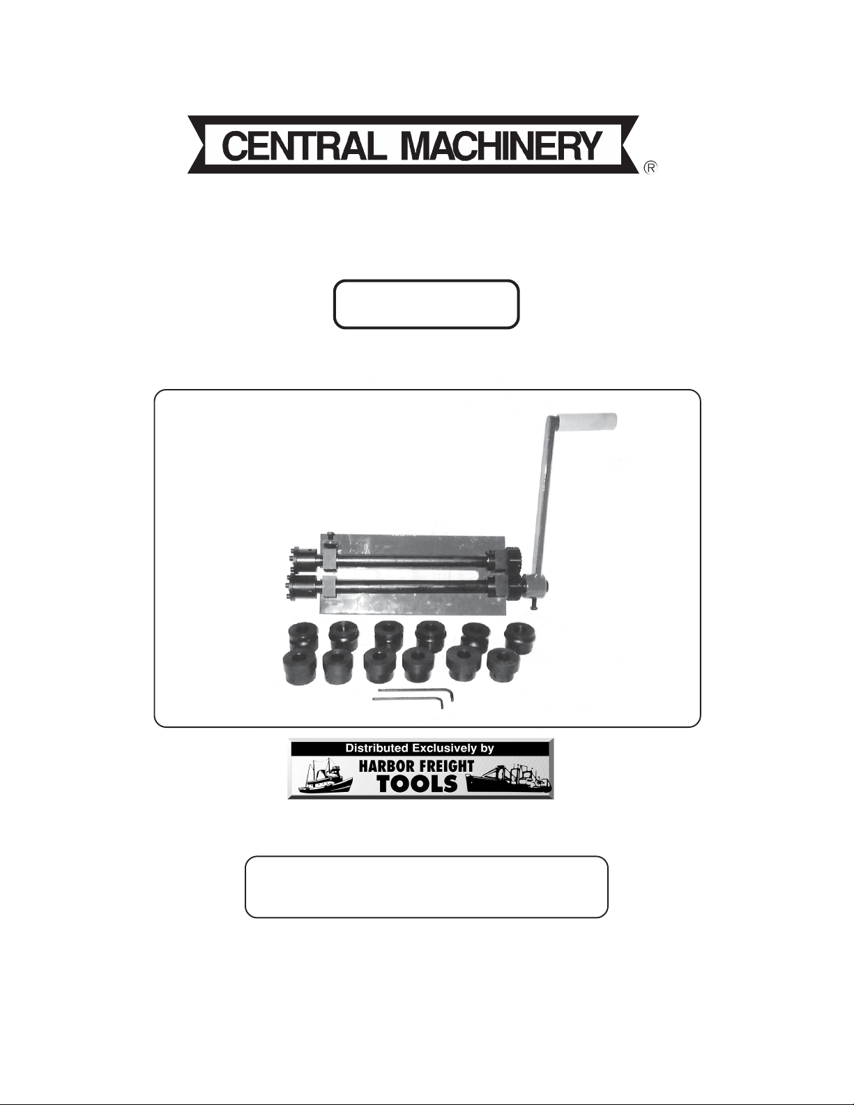
12” BEAD ROLLER KIT
®
Model 93364
ASSEMBLY AND OPERATING INSTRUCTIONS
Due to continuing improvements, actual product may differ slightly from the product described herein.
3491 Mission Oaks Blvd., Camarillo, CA 93011
Visit our Web site at: http://www.harborfreight.com
TO PREVENT SERIOUS INJURY,
READ AND UNDERSTAND ALL WARNINGS
AND INSTRUCTIONS BEFORE USE.
Copyright 2005 by Harbor F reight Tools®. All rights reserved. No portion of this
manual or any artwork contained herein may be reproduced in any shape or form
©
without the express written consent of Harbor Freight Tools.
For technical questions, please call 1-800-444-3353.
Page 2
PRODUCT SPECIFICATIONS
Item Description
Maximum Throat Depth Capacity 12”
Maximum Thickness Capacity 18 Gauge
Accessories 1/4”, 3/8”, 1/2” Bead Rollers
1/16”, 1/8”, 1/4” Flange Rollers
Rolling Shear
Shearing Mandrel
Base Dimensions 14-5/8” L x 6-3/8” W
Unit Weight 38.3 Pounds
SAVE THIS MANUAL
You will need this manual for the safety warnings and precautions, assembly, operating,
inspection, maintenance and cleaning procedures, parts list and assembly diagram. K eep
your invoice with this manual. Write the invoice number on the inside of the front cover.
Keep this manual and in voice in a safe and dry place for future reference.
GENERAL SAFETY RULES
When unpacking, check to mak e sure all the parts shown in the Parts List on page 11 are
included. If any parts are missing or broken, please call Harbor Freight T ools at the n umber
shown on the front cover of this manual as soon as possible.
GENERAL SAFETY RULES
IMPORTANT SAFETY INSTRUCTIONS
WARNING!
READ AND UNDERSTAND ALL INSTRUCTIONS
Failure to follow all instructions detailed in this manual may
result in serious personal injury .
SAVE THESE INSTRUCTIONS
WORK AREA
1. Keep your work area clean and well lit. Cluttered and dark work areas invite
accidents.
SKU 93364 For technical questions, please call 1-800-444-3353 PAGE 2
Page 3

2. Keep bystanders, children, and visitors away while operating the Bead
Roller Kit. Distractions can cause you to lose control.
PERSONAL SAFETY
3. Stay alert. W atch what you are doing, and use common sense when operating a
power tool. Do not use a power tool while tired or under the influence of drugs,
alcohol, or medication. A moment of inattention while operating power tools may
result in serious personal injury.
4. Dress properly. Do not wear loose clothing or jewelry. Contain long hair. Keep
your hair, clothing, and gloves away from moving parts. Loose clothes, jewelry, or
long hair can be caught in moving parts.
5. Do not overreach. Keep proper footing and balance at all times. Proper footing
and balance enables better control of the Bead Roller Kit in unexpected
situations.
6. Always wear ey e and hand pr otection. Wear ANSI approved safety impact
goggles and heavy duty work gloves when assembling and using this product.
TOOL USE AND CARE
7. Do not force the Bead Roller Kit. Use the correct product for your application.
The correct product will do the job better and safer at the rate for which it is
designed.
8. Store idle tools and equipment out of reach of children and other untrained
people. Tools and equipment are dangerous in the hands of untrained users.
9. Maintain the Bead Roller Kit with care. Keep this product clean. A properly
maintained tool is easier to control. Do not use damaged tools and equipment.
Tag damaged tools and equipment “Do not use” until repaired.
10. Check for misalignment or binding of moving parts, loose or broken parts,
and any other condition that may affect the Bead Roller Kit’s operation. If
damaged, have the Bead Roller Kit serviced before using. Many accidents are
caused by poorly maintained tools and equipment.
11. Use only accessories that are recommended by the manufacturer for your
model. Accessories that may be suitable for one product may become hazardous
when used on another product.
SKU 93364 For technical questions, please call 1-800-444-3353 PAGE 3
Page 4

SERVICE
12. Bead Roller Kit service must be performed only by qualified service
technician. Service or maintenance performed by unqualified personnel could
result in a risk of injury .
13. When servicing the Bead Roller Kit, use only identical replacement parts.
Follow instructions in the
manual. Use of unauthorized parts or failure to follow maintenance instructions
may create a risk of electric shock or injury .
“Inspection, Maintenance, And Cleaning”
section of this
SPECIFIC SAFETY RULES
1. Maintain labels and nameplates on the Bead Roller Kit. These carry important
information. If unreadable or missing, contact Harbor Freight Tools for a
replacement.
2. Use the right product for the job. There are certain applications for which this
product was designed. Do not use small tools, equipment, or attachments to do
the work of larger industrial tools, equipment, or attachments. Do not use this
product for a purpose for which it was not intended.
3. Avoid moving parts during operation. Keep fingers and hands away from
gears, rollers, dies , cutting plates , and all moving parts.
4. T wo person operation. Two people are needed to operate the Bead Roller
machine. One person is needed to feed the sheet metal, while a second person
cranks the Bead Roller’s handle.
5. 18 Gauge limit. Do not use the Bead Roller on metal thicker than 18 gauge.
6. During set up and operation. Use a standard shop vise (not included) to hold
the Bead Roller assembly (see Figure A, page 5). Make sure the vise is bolted
or permanently fastened to a flat, lev el, sturdy workbench capab le of supporting
the weight of the Bead Roller, vise, workpieces, and any additional tools.
7. Industrial applications must follow OSHA requirements.
8. Store idle tools. When not in use, store the Bead Roller Kit in a clean, dry, saf e
location out of reach of children.
9. WARNING! The warnings and cautions discussed in this manual cannot
cover all possib le conditions and situations that may occur. It must be understood
by the operator that common sense and caution are factors which cannot be built
into this product, but must be supplied by the oper ator .
SKU 93364 For technical questions, please call 1-800-444-3353 PAGE 4
Page 5

INSTALLATION AND ASSEMBLY INSTRUCTIONS
1. CAUTION! The Bead Roller is heavy. Always use
two
people when lifting or
moving the tool.
2. Use a standard shop vise (not included) to securely hold the Bead Roller. Make
sure the vise is bolted or permanently fastened to a flat, level, sturdy workbench
capable of supporting the weight of the Bead Roller, vise, workpieces, and any
additional tools. (See Figure A.)
3. Once the Bead Roller is secured in a vise, align the flat inner edge of the Handle
(12) with the flat edge of the Active Roller (3). Then, slide the Handle onto the
Active Roller. (See Figure A.)
4. Use a 3/8” open end wrench to firmly tighten the Bolt (11). (See Figure A.)
ACTIVE R OLLER (3)
BOL T (11)
VISE
(NOT INCLUDED)
HANDLE (12)
FIGURE A
ALIGNMENT
NOTE: The Bead Roller has been factory pre-aligned. Howev er, depending on
use the Bead Roller may eventually require re-alignment. Poor alignment will
affect the quality of metal forming and the ability of the tool to cut sheet metal. If
you experience either of these problems, perform the following alignment steps:
1. Set up the Bead Roller with Cutting Dies (10-1, 10-2) and Cutting Plates (9) as
shown in the illustration. (See Figure B, next page.)
2. Inspect the Cutting Plates (9). When the Bead Roller is properly aligned, the
SKU 93364 For technical questions, please call 1-800-444-3353 PAGE 5
Page 6

edges of the Cutting Plates should be touching (or almost touching). If they are
not, perform the following steps:
3. Use the 4mm He x Key Wrench (27) to loosen the two He x Bolts (16) that secure
the Gear (5) and Collar (6) to the Active Roller (3). (See Figure B.)
4. Slide the Active Roller (3) until the edges of the Cutting Plates (9) are touching.
(See Figure B.)
5. By hand, move the Collar (6) so its edge is touching the Roll Block (2). Then,
re-tighten its Hex Bolt (16). (See Figure B.)
6. Mo v e the Gear (5) so its side is touching the Roll Bloc k (2). Then, re-tighten its
Hex Bolt (16). (See Figure B.)
7. NOTE: If the edges are touching and the Bead Roller does not cut material
properly, adjust the roller tension as discussed in the section
Tension”
on page 8 of this manual.
ROLL BLOCK (2)
“Adjusting Roller
CUTTING PLA TES
(9)
CUTTING DIES
(10-1, 10-2)
COLLAR (6)
GEAR (5)
FIGURE B
CHANGING ROLLERS
NOTE: The Bead Roller Kit comes with a variety of Bead Dies and Flange Dies,
as well as the Cutting Dies and Cutting Plates that are assembled onto the tool
beforeshipping. Use the following instructions when you change Dies:
To remove the Cutting Dies (10-1, 10-2) and Cutting Plates (9):
1. Use a 3/8” wrench to loosen the Thickness Adjusting Bolt (15).
(See Figure C, next page.)
SKU 93364 For technical questions, please call 1-800-444-3353 PAGE 6
Page 7

2. Use the 5mm (26) He x Key Wrench to remove the eight Hex Bolts (18) securing
the Cutting Plates (9) to the Cutting Dies (10-1, 10-2). (See Figure C.)
3. Remove the Cutting Plates (9). (See Figure C.)
4. Use a 14mm wrench to remove the two End Bolts (14) securing the Cutting Dies
(10-1, 10-2) to the Active Roller (3) and P ositiv e Roller (4). Then, remov e the
Washers (13). (See Figure C.)
5. Use the 4mm Hex Ke y Wrench (27) to loosen the Hex Bolts (16) that loc k the
Cutting Dies (10-1, 10-2) onto the Active Roller (3) and Positive Roller (4).
(See Figure C.)
6. Remove the Cutting Dies (10-1, 10-2). (See Figure C.)
THICKNESS ADJUSTING BOL T (15)
CUTTING DIES
(10-1, 10-2)
HEX
BOLTS
(18)
CUTTING
PLATES
(9)
WASHERS
(13)
ACTIVE R OLLER (3)
POSITIVE ROLLER (4)
FIGURE C
Installing Bead And Flange Dies:
1. Select the correct Bead Dies (19-1 thru 21-2) or Flange Dies (22-1 thru 24-2) for
the job you are going to perform.
2. Slide both Dies onto the Activ e Roller (3) and Positive Roller (4) at the same time.
Make sure the Hex Bolts (16) on the Dies are positioned over the flat edges of the
Active Roller and Positive Roller. (See Figure D, next page.)
3. By hand, install the tw o End Bolts (14). Then, tighten the End Bolts with a 14mm
wrench. (See Figure D.)
4. Make sure to tighten the two Hex Bolts (16) on the Dies. (See Figure D.)
SKU 93364 For technical questions, please call 1-800-444-3353 PAGE 7
Page 8

END
BOLTS
(14)
WASHERS
(13)
(19-1 THRU 24-2)
THICKNESS ADJUSTING BOL T
(15)
ACTIVE
ROLLER
(3)
ROLL BLOCK
(2)
DIES
POSITIVE
ROLLER
(4)
FIGURE D
Adjusting Roller Tension:
1. Adjust the Thickness Adjusting Bolt (15) only finger tight. (See Figure E.)
2. Use a 3/8” wrench to tighten the Thic kness Adjusting Bolt (15) 1 to 3 turns, depending on desired results. (See Figure E.)
THCKNESS ADJUSTING BOL T (15)
FIGURE E
SKU 93364 For technical questions, please call 1-800-444-3353 PAGE 8
Page 9

OPERATING INSTRUCTIONS
1. CAUTION! Do not exceed the maximum thickness capacity (18 gauge) of
the Bead Roller.
2. Always use two people to operate the Bead Roller. One person should guide the
metal along the Roller while a second person cranks the Handle (12) of the tool.
Metal forming typically requires good communication between the person
cranking the Handle and the person guiding the metal, particularly on corners.
NOTE: It is recommended to practice all cutting/beading pr ocedures first on
scrap metal. (See Figure F .)
3. Mark your rib , flange pattern, or cut-line on the workpiece. (See Figure F.)
4. Insert and guide the workpiece through the Cutting Dies or Flange Dies while
another person cranks the Handle (12) of the tool. (See Figure F.)
5. When finished using the Bead Roller Kit, make sure to store the tool and its
accessories in a clean, dry , saf e location out of reach of children.
PERSON #1
CRANKS
HANDLE
(15)
PERSON #2)
FEEDS
WORKPIECE
FIGURE F
INSPECTION, MAINTENANCE, AND CLEANING
1. Before each use, inspect the general condition of the Bead Roller Kit. Check for
misalignment or binding of moving parts, damaged or loose parts, dull or worn
Cutting Dies and Flange Dies, and any other condition that ma y affect the tool’s
safe operation. If abnormal noise or vibration occurs, have the problem cor
rected before further use. Do not use damaged equipment.
2. Periodically, use grease to lubricate all moving parts of the Bead Roller.
SKU 93364 For technical questions, please call 1-800-444-3353 PAGE 9
Page 10

3. T o clean, use a clean cloth and mild detergent or non-flammable solvent. Then,
dry.
4. CAUTION! All maintenance, service, and repairs not discussed in this
manual should only be performed by a qualified service technician.
TROUBLESHOOTING
Problem Possible Solution
Tool not cutting properly or not
forming a proper bead.
Handle turns with difficulty. Check to make sure workpiece is no thicker than 18 gauge.
Check to make sure workpiece is no thicker than 18 gauge.
Check Cutting Dies/Flange Dies for proper alignment.
Make sure all Hex Bolts are tightened.
Check Collars for proper setting and adjustment.
Check for worn Cutting Plates/Flange Dies. If necessary, replac e
Cutting Plates/Flange Dies.
Lubricate all moving parts.
Check for proper adjustment of Thickness Adjusting Bolt.
Check for damaged parts (Gears, Rollers, Dies, Flanges, etc.)
Lubricate all moving parts.
PLEASE READ THE FOLLOWING CAREFULLY
THE MANUFACTURER AND/OR DISTRIBUTOR HAS PROVIDED THE PARTS LIST AND ASSEMBLY
DIAGRAM IN THIS MANUAL AS A REFERENCE TOOL ONLY. NEITHER THE MANUFACTURER OR
DISTRIBUTOR MAKES ANY REPRESENTATION OR W ARRANTY OF ANY KIND T O THE BUYER THAT HE
OR SHE IS QUALIFIED TO REPLA CE ANY PARTS OF THE PRODUCT. IN FACT, THE MANUF A CTURER
AND/OR DISTRIBUTOR EXPRESSLY ST A TES THA T ALL REP AIRS AND PARTS REPLACEMENTS SHOULD
BE UNDERTAKEN BY CERTIFIED AND LICENSED TECHNICIANS, AND NO T BY THE BUYER. THE BUYER
ASSUMES ALL RISKS AND LIABILITY ARISING OUT OF HIS OR HER REPAIRS TO THE ORIGINAL
PRODUCT OR REPLACEMENT PARTS THERET O, OR ARISING OUT OF HIS OR HER INSTALLATION OF
REPLACEMENT P AR TS THERET O.
SKU 93364 For technical questions, please call 1-800-444-3353 PAGE 10
Page 11

PARTS LIST
Part # Description Qty. Part # Description Qty.
1 Base 1 17 Bushing 1
2 Roll Block 4 18 Hex Bolt (M6x10) 8
3 Active Roller 1 19-1 ½” Half-Round Die (Convex) 1
4 Positive Roller 1 19-2 ½” Half-Round Die (Concave) 1
5 Gear 2 20-1 3/8” Half-Round Die (Convex) 1
6 Collar 2 20-2 3/8” Half-Round Die (Concave) 1
7 Roll Block Bolt (M14x30) 4 21-1 ¼” Half-Round Die (Convex) 1
8 Flat Washer (14mm) 4 21-2 ¼” Half-Round Die (Concave) 1
9 Cutting Plate 2 22-1 ¼” Flange Die 1
10-1 Long Cutting Die 1 22-2 ¼” Flange Die 1
10-2 Short Cutting Die 1 23-1 1/8” Flange Die 1
11 Bolt (M10x30) 1 23-2 1/8” Flange Die 1
12 Handle 1 24-1 1/16” Flange Die 1
13 Washer (10mm) 2 24-2 1/16” Flange Die 1
14 End Bolt (M10x20) 2 25 Spring Washer (6mm) 8
15 Thickness Adjusting Bolt (M10x30) 1 26 Hex Key Wrench (5mm) 1
16 Hex Bolt (M8x10) 18 27 Hex Key Wrench (4mm) 1
PART SELECTION GUIDE
Note: Items are larger than shown in this illustration.
1/4” HALF-ROUND DIE
(21-1, 22-2)
1/16” FLANGE DIE
(24-1, 24-2)
3/8” HALF-ROUND DIE
(20-1, 20-2)
1/8” FLANGE DIE
(23-1, 23-2)
1/2” HALF-ROUND DIE
(19-1, 19-2)
1/4” FLANGE DIE
(22-1, 22-2)
SKU 93364 For technical questions, please call 1-800-444-3353 PAGE 11
Page 12

ASSEMBLY DIAGRAM
NOTE:
and are not available individually as replacement parts.
Some parts are listed and shown for illustration purposes only ,
SKU 93364 For technical questions, please call 1-800-444-3353 PAGE 12
 Loading...