

Page 1

®
WALLPAPER STEAMER
Model 91098
ASSEMBLY AND OPERATING INSTRUCTIONS
3491 Mission Oaks Blvd., Camarillo, CA 93011
Visit our Web site at: http://www.harborfreight.com
Copyright© 2004 by Harbor Freight Tools®. All rights reserved. No portion of this
manual or any artwork contained herein may be reproduced in any shape or form
without the express written consent of Harbor Freight Tools.
For technical questions, please call 1-800-444-3353.
Page 2
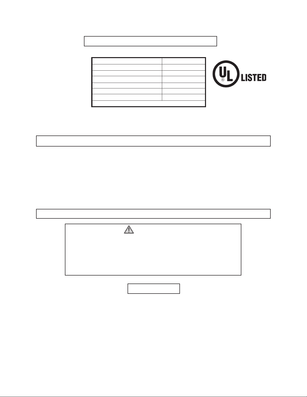
PRODUCT SPECIFICATIONS
Motor 120V, 1200 Watts
Tank Capacity 1.2 Gallons
Steam Duration 140 Minutes
Working Temperature 212° Fahrenheit
Rise Time To Steam 5 to 25 Minutes
Steam Plate 7” W x 11” L
Po wer Cord 16 AWG x 6 Feet
Features a Thermal Safety Cut-off Switch.
E224797
SAVE THIS MANUAL
You will need this manual for the safety warnings and precautions,
assembly , operating, inspection, maintenance and cleaning procedures , parts
list and assembly diagram. Keep your invoice with this manual. Write the
invoice number on the inside of the front co ver . K eep this manual and inv oice
in a safe and dry place for future reference.
GENERAL SAFETY RULES
WARNING!
READ AND UNDERSTAND ALL INSTRUCTIONS
Failure to follow all instructions listed below may result in
electric shock, fire, and/or serious injury .
SAVE THESE INSTRUCTIONS
WORK AREA
1. Keep your w ork area clean and well lit. Cluttered benches and dark areas invite
accidents.
2. Do not operate power tools in explosive atmospheres, such as in the presence
of flammable liquids, gases, or dust. P ower tools create sparks which may ignite
the dust or fumes.
3. Keep bystanders, children, and visitors away while operating a power tool.
Distractions can cause you to lose control. Protect others in the work area from
escaping steam. Provide barriers or shields as needed.
SKU 91098
PAGE 2
Page 3

ELECTRICAL SAFETY
4. Grounded tools must be plugged into an outlet pr operly installed and grounded
in accordance with all codes and ordinances. Never remove the grounding
prong or modify the plug in any way. Do not use any adapter plugs. Check
with a qualified electrician if you are in doubt as to whether the outlet is properl y
grounded. If the tools should electrically malfunction or break down, grounding
provides a low resistance path to carry electricity away from the user.
5. Double insulated tools are equipped with a polarized plug (one blade is wider
than the other). This plug will fit in a polarized outlet only one way . If the plug
does not fit fully in the outlet, reverse the plug. If it still does not fit, contact a
qualified electrician to install a polarized outlet. Do not change the plug in
any way . Doub le insulation eliminates the need for the three wire grounded power
cord and grounded power supply system.
6. Av oid body contact with grounded surfaces suc h as pipes, radiator s, ranges,
and refrigerators. There is an increased risk of electric shock if your body is
grounded.
7. Do not expose power tools to rain or wet conditions. Water entering a power
tool will increase the risk of electric shock.
8. Do not abuse the P ower Cord. Ne ver use the Po wer Cord to carry the tools or
pull the Plug from an outlet. K eep the Power Cord a way from heat, oil, sharp
edges, or moving parts. Replace damaged Power Cor ds immediately . Damaged
Power Cords increase the risk of electric shock.
9. When operating a power tool outside, use an outdoor e xtension cord marked
“W-A” or “W”. These extension cords are rated for outdoor use, and reduce the
risk of electric shock.
PERSONAL SAFETY
10. Stay alert. W atch what you are doing, and use common sense when operating
a power tool. Do not use a power tool while tired or under the influence of
drugs, alcohol, or medication. A moment of inattention while operating power
tools may result in serious personal injury.
11. Dress properly. Do not wear loose clothing or jewelry. Contain long hair.
12. Do not overreach. Keep proper footing and balance at all times. Proper footing
and balance enables better control of the power tool in unexpected situations.
13. Use safety equipment. Al wa ys wear e y e pr otection. Rubber glov es , protectiv e
clothing, and non-skid safety shoes, must be used for appropriate conditions.
SKU 91098
PAGE 3
Page 4

TOOL USE AND CARE
14. Do not force the tool. Use the correct tool for your application. The correct tool
will do the job better and safer at the rate for which it is designed.
15. Disconnect the Power Cor d Plug fr om the power sour ce and allo w the unit to
cool before making any adjustments, changing accessories, or storing the
tool.
16. Store idle tools out of reach of children and other untrained persons. Tools
are dangerous in the hands of untrained users.
17. Maintain tools with care. Keep tools and c lean. Do not use a damaged tool. Tag
damaged tools “Do not use” until repaired.
18. Check for misalignment or binding of moving parts, breakage of parts, and
any other condition that may aff ect the tool’ s operation. If dama ged, ha ve the
tool serviced before using. Many accidents are caused by poorly maintained
tools.
19. Use only accessories that are recommended by the manufacturer for your
model. Accessories that may be suitable for one tool may become hazardous
when used on another tool.
SERVICE
20. T ool service must be perf ormed only b y qualified repair personnel. Service or
maintenance performed by unqualified personnel could result in a risk of injury.
21. When servicing a tool, use only identical replacement parts. Follow
instructions in the
manual. Use of unauthor ized parts or failure to follow maintenance instructions
may create a risk of electric shock or injury.
“Inspection, Maintenance, And Cleaning”
section of this
SPECIFIC SAFETY RULES
1. Maintain labels and nameplates on the Steamer. These carry important
information. If unreadable or missing, contact Harbor Freight T ools f or a replacement.
2. Always wear safety impact eye goggles when using the Steamer . Using personal
safety devices reduce the risk for injury. Safety impact eye goggles are available
from Harbor Freight T ools.
3. Maintain a safe working environment. Keep the work area well lit. Make sure
there is adequate surrounding workspace. Always keep the work area free of
obstructions, grease, oil, trash, and other debris. Do not use a power tool in areas
near flammable chemicals, dusts, and v apors. Do not use this product in a damp or
wet location.
SKU 91098
PAGE 4
Page 5

4. Avoid unintentional starting. Make sure y ou are prepared to begin w ork before
plugging in the Steamer.
5. Do not force the Steamer . This tool will do the work better and safer at the speed
and capacity for which it was designed.
6. Never leave the Steamer unattended when it is plugged into an electrical outlet.
Unplug it from its electrical outlet and allow it to cool before leaving.
7. Always unplug the Steamer fr om its electrical outlet and allow it to cool before
performing inspection, maintenance, cleaning procedures, or changing
accessories.
8. Do not allow water or steam to enter the plug or socket.
9. Wear heat resistant gloves. The water to make steam is heated to 212° F ahrenheit.
Wear protective clothing and protect your hands.
10. Never remove the Filler Cap (5) or detach the Hose (4) while the appliance is
operating or before it has cooled.
11. Do not pull on the Hose (4) or carry the unit by the Hose (4) or Power
Cord (12).
12. Keep the work area clear of children, pets, and bystanders.
13. During operation, do not stand or step on the Boiler Unit (8) or Hose (4).
14. Never bloc k the safety valve.
15. Only operate the unit when the Boiler Unit (8) is on a flat, level surface. Failure
to do so will result in severe overheating, damaging the unit.
16. Never point the Hose (4) or any attachment at anyone.
17. Always keep all attachments a way fr om the face and body. Beware of dripping
hot water, and regularly empty collected condensation from the Steam Plate (6);
especially prior to stripping ceilings and high areas.
18. After disconnecting power, wait at least two minutes before removing the
Filler Cap (5) to refill the Boiler Unit (8).
19. Do not overfill the reservoir. Use only standard tap water. Never add detergents
or chemicals.
20. Never use the Steamer when the Boiler Unit is in a suspended position. This
will result in possible injury and damage to the unit.
21. Extreme care must be used when operating the Steamer in close pr oximity to
standing water. Alwa ys be aware of the danger of electrocution from stored w ater
in baths, sinks, etc.
22. Do not use the Steamer if the Power Cord (12) is damaged.
SKU 91098
PAGE 5
Page 6

GROUNDING
WARNING!
Improperly connecting the grounding wire can result in the risk of
electric shock. Check with a qualified electrician if you are in doubt as to
whether the outlet is properly grounded. Do not modify the po wer cord plug
provided with the tool. Nev er remov e the grounding prong from the plug. Do
not use the tool if the power cord or plug is damaged. If damaged, have it
repaired by a service facility before use . If the plug will not fit the outlet, hav e
a proper outlet installed by a qualified electrician.
GROUNDED T OOLS: TOOLS WITH THREE PRONG PLUGS
1. Tools marked with “Grounding Required” have a three wire cord and three prong
grounding plug. The plug must be connected to a properly grounded outlet. If the
tool should electrically malfunction or break down, grounding provides a low
resistance path to carry electricity away from the user, reducing the risk of electric
shock. (See Figure A.)
2. The grounding prong in the plug is connected through the green wire inside the
cord to the grounding system in the tool. The green wire in the cord must be the
only wire connected to the tool’s grounding system and must never be attached to
an electrically “live” terminal.
(See Figure A.)
3. Your tool must be plugged into an
appropriate outlet, properly installed
and grounded in accordance with all
codes and ordinances. The plug and
outlet should look like those in the
illustration to the right. (See Figure A.)
FIGURE A
SKU 91098
PAGE 6
Page 7

DOUBLE INSULA TED T OOLS: TOOLS WITH TWO PRONG PLUGS
4. Tools marked “Double Insulated” do not require grounding. They have a special
double insulation system which satisfies OSHA requirements and complies with
the applicable standards of Underwriters Laboratories, Inc., the Canadian Standard
Association, and the National Electrical Code. (See Figure B.)
5. Double insulated tools may be used in either of the 120 volt outlets shown in the
following illustration. (See Figure B.)
FIGURE B
EXTENSION CORDS
1.
2. As the distance from the supply outlet increases, you must use a heavier gauge
3. The smaller the gauge number of the wire, the greater the capacity of the cord. F or
4. When using more than one extension cord to make up the total length, make sure
5. If you are using one extension cord for more than one tool, add the nameplate
Grounded
use either a two or three wire extension cord.
extension cord. Using extension cords with inadequately siz ed wire causes a serious
drop in voltage, resulting in loss of po wer and possible tool damage.
(See Figure C, next page.)
example, a 14 gauge cord can carry a higher current than a 16 gauge cord.
(See Figure C.)
each cord contains at least the minimum wire size required. (See Figure C.)
amperes and use the sum to determine the required minimum cord size.
(See Figure C.)
tools require a three wire extension cord.
Double Insulated
tools can
SKU 91098
PAGE 7
Page 8

6. If you are using an extension cord outdoors, make sure it is marked with the suffix
“W-A” (“W” in Canada) to indicate it is acceptable for outdoor use.
7. Make sure your extension cord is properly wired and in good electrical condition.
Always replace a damaged e xtension cord or have it repaired by a qualified electrician
before using it.
8. Protect your extension cords from sharp objects, e xcessiv e heat, and damp or wet
areas.
RECOMMENDED MINIMUM WIRE GAUGE FOR EXTENSION CORDS*
(120 VOLT)
NAMEPLATE
AMPERES
(At Full Load)
25 FEET 50 FEET 75 FEET 100 FEET 150 FEET
0 - 2.0 18 18 16 16 16
2.1 - 3.4 18 18 16 14 14
3.5 - 5.0 18 18 16 14 12
5.1 - 7.0 18 16 14 12 12
7.1 - 12.0 18 14 12 10 -
12.1 - 16.0 14 12 10 - -
16.1 - 20.0 12 10 - - -
EXTENSION CORD LENGTH
FIGURE C
*Based on limiting the line voltage drop
to five volts at 150% of the rated amperes.
SYMBOLOGY
Double Insulated
Canadian Standards
Association
Underwriters
Laboratories, Inc.
V ~
A
n
o
xxxx/min.
Volts Alternating Current
Amperes
No Load Revolutions
per Minute (RPM)
SKU 91098
PAGE 8
Page 9

UNPACKING
When unpacking, check to make sure all the par ts shown on the Parts List on
page 12 are included. If any parts are missing or broken, please call Harbor Freight Tools
at the number shown on the cover of this manual as soon as possible.
ASSEMBLY AND OPERATING INSTRUCTIONS
NOTE: F or additional inf ormation regarding the parts listed in the following pages, refer to
the Assembly Diagram on page 12.
Caution: Always mak e sure the P ow er Cord of the W allpaper Steamer is unplugged from
its electrical outlet and the unit is cool
Filling The Boiler Unit (8).
Refer to the Assembly Drawing on page 12.
1. Remove the Filler Cap (5).
2. Fill the Boiler Unit (8) with clean, hot water all the wa y to capacity . Replace the Filler
Cap (5). Note: At full capacity, the unit should heat up in approximately 25 minutes ,
and produce steam for 140 minutes.
Warning!! Do not overfill the Boiler Unit (8) or water will be forced up the steam hose,
burning the operator and damaging the unit. A safety cut-off will turn off the unit if
the water level drops below the “MIN” line. If that happens, let the unit cool down
and wait a minimum of 2 minutes before removing the Filler Cap (5) prior to refill
and start up. The safety cut-off feature will not work if the unit is tilted during
operation. Y ou can permanentl y damage the unit by allowing the water level to
fall too low by working with the unit tilted.
prior
to making any adjustments on the tool.
Connecting the Steam Hoses.
Refer to FIGURES 1 and 2 below.
Note: The Hose and attachments are all threaded. Alw ays thread the plastic parts gently .
Forcing plastic threaded parts may break them, damaging the product.
1. When connecting the Nozzle (7), Steam Plate (6), or Brush (1) to the Hose (4),
gently thread on the appropriate attachment as shown in FIGURE 1.
2. FIGURE 2 shows how to disconnect the Brush(1), Connector(3), Long Pipes (9), or
Brush Handle (2).
FIGURE 2
SKU 91098
FIGURE 1
PAGE 9
Page 10

OPERATING INSTRUCTIONS
Wallpaper Stripping
FIGURE 3
Note: FIGURE 3 shows the
Steam Plate (6) connected
to the Hose (4), which is
connected to the Boiler
Unit (8).
1. After connecting the Steam Plate (6) accessory to the Boiler Unit (8), plug in the
Power Cord (12) and wait approximately 25 minutes for the unit to produce steam.
Warning!! Once the unit is heated, it is constantly produces steam that causes
severe burns if it comes in contact with unprotected skin. Keep children, pets,
and bystanders out of the area, and wear appropriate protective clothing. This
hot steamer can also damage property.
2. Hold the Steam Plate (6) flat against the wallpaper for approximately 10 seconds.
Then, move the plate immediately , to the spot ne xt to the one just steamed. Remove
the wallpaper from the steamed section with the aid of a scraper (not included). If
the wallpaper does not easily come off, steam it for a slightly longer duration.
Wallpapers and glues vary, with some requiring longer steam sessions.
3. Continue operating until the water level is low (but above the “MIN” line). Then,
unplug the unit and wait a minimum of two minutes for it to cool. BEWARE of
escaping steam as you remove the Filler Cap (5). Refill the unit.
4. When finished, allow the unit to cool completely and then empty the unit. Always
store the unit empty.
Note: You may use this Steamer for other cleaning applications using the included
accessories. FIGURE 4 shows the Brush (1), Long Pipes (9)
and the Brush Handle (2) connected to the Hose (4) and the
Boiler Unit (8) for a typical steam cleaning operation.
FIGURE 4
1. To Assemble the Handle (2) and Brush (1):
Insert the Hose (4) through the Brush Handle (2) and one
Long Pipe (9). You can use the Connector (3) and a
second Long Pipe (9) to further lengthen the handle, if
desired. Screw the Hose (4) onto the Brush (1), as
shown in FIGURE 1. Then, connect the Long Pipe (9)
to the Brush (1). Refer to FIGURE 4.
SKU 91098
PAGE 10
Page 11

TROUBLESHOOTING
The Boiler Unit (8) fails to produce steam.
1. Check that the Power Cord (12) is properly plugged into the wall outlet and the
Boiler Unit (8).
2. If the safety cut-off engaged, it will need ample time to cool and reset.
3. The safety cut-off device was damaged from working with a tilted unit.
The Boiler Unit (8) leaks steam from the pressure release valve.
1. The pressure release valve is a special lo w pressure valv e that cannot be replaced
by another valv e. If steam leaks from the valve, the most likely cause is a bloc kage
in the steam Hose (4). Allow the unit to cool and chec k the Hose (4) f or bloc kages.
INSPECTION, MAINTENANCE, AND CLEANING
1. WARNING! Make sure the unit is unplugged from its electrical outlet and
thoroughly cooled down before perf orming any inspection, maintenance, or cleaning
procedures.
2. BEFORE EACH USE, inspect the general condition of the Wallpaper Steamer . Check
for loose screws , misalignment or binding of moving parts, crack ed or broken parts,
damaged electrical wiring, and any other condition that may affect its saf e operation.
If abnormal noise or vibration occurs, have the problem corrected before further
use. Do not use damaged equipment.
3. Wipe down the unit and dry the accessories with the Rag (10).
4 . Areas with hard water, or when using tap water, will eventually leave a scaly film on
the element in the Boiler Unit (8). Use an over-the-counter descaling product to
clean out the Boiler Unit (8). Follow the descaling product manufacturer’ s instructions.
SKU 91098
PAGE 11
Page 12

ASSEMBLY DIAGRAM
2
1
3
9
9
12
10
8
11
4
5
7
NOTE: Some parts are listed and shown for illustration purposes only, and
are not available individually as replacement parts.
PARTS LIST
6
Part No. Description Part No. Description
1 Brush 7 Nozzle
2 Brush Handle 8 Boiler Unit
3 Connector 9 Long Pipe (2)
4 Hose 10 Rag
5 Filler Cap 11 Squeegee
6 Steam Plate 12 Power Cord
PLEASE READ THE FOLLOWING CAREFULLY
THE MANUFACTURER AND/OR DISTRIBUTOR HAS PROVIDED THE PARTS LIST AND
ASSEMBLY DIAGRAM IN THIS MANUAL AS A REFERENCE TOOL ONLY. NEITHER THE
MANUFACTURER OR DISTRIBUTOR MAKES ANY REPRESENTATION OR WARRANTY OF ANY
KIND TO THE BUYER THA T HE OR SHE IS QUALIFIED TO MAKE ANY REP AIRS TO THE PRODUCT ,
OR THAT HE OR SHE IS QUALIFIED TO REPLACE ANY PARTS OF THE PRODUCT. IN FACT, THE
MANUFACTURER AND/OR DISTRIBUTOR EXPRESSLY STATES THAT ALL REPAIRS AND PARTS
REPLACEMENTS SHOULD BE UNDERTAKEN BY CERTIFIED AND LICENSED TECHNICIANS, AND
NOT BY THE BUYER. THE BUYER ASSUMES ALL RISK AND LIABILITY ARISING OUT OF HIS OR
HER REPAIRS TO THE ORIGINAL PRODUCT OR REPLACEMENT PARTS THERETO, OR ARISING
OUT OF HIS OR HER INSTALLATION OF REPLACEMENT PARTS THERETO.
SKU 91098
PAGE 12
 Loading...