

Page 1
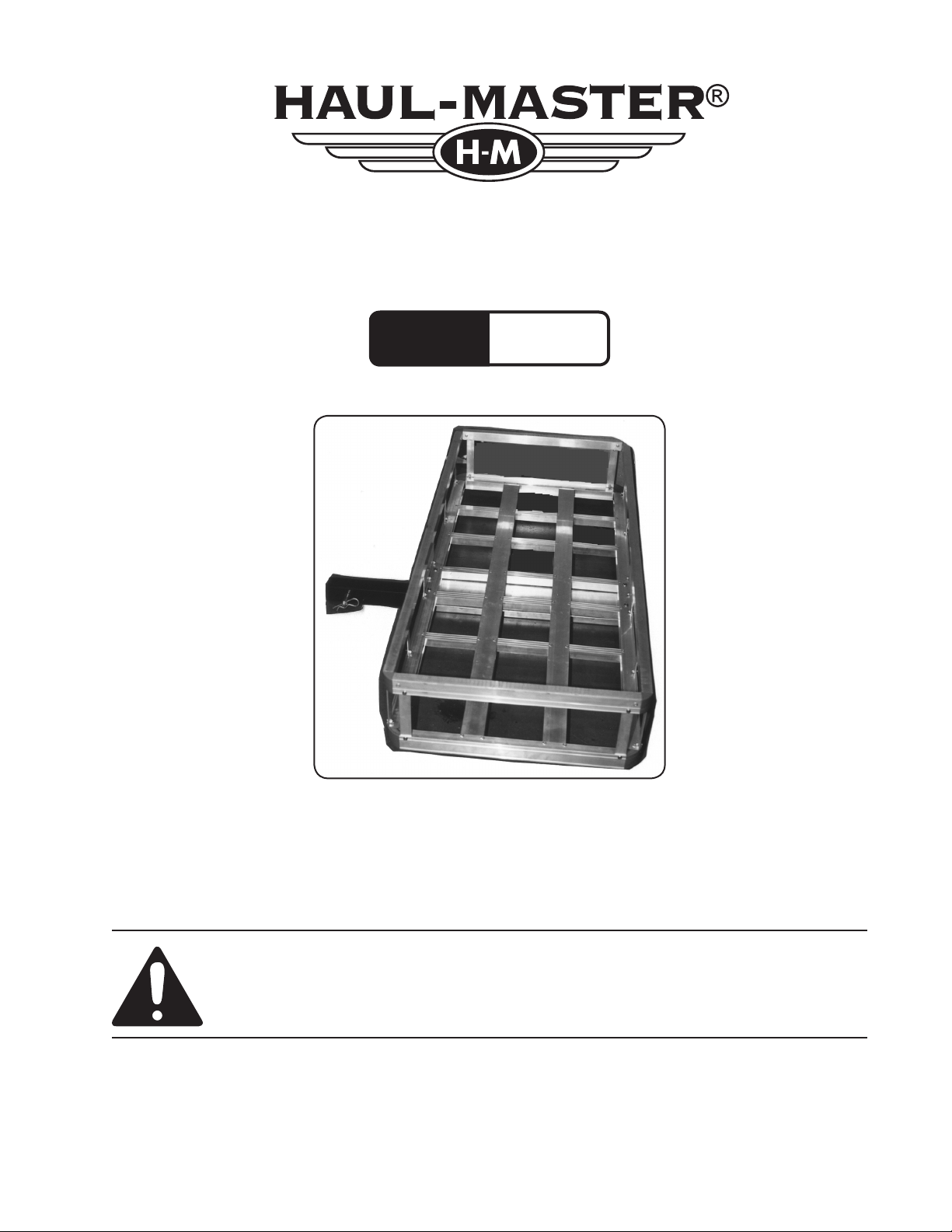
500 LB. ALUMINUM
Model
92655
CARGO CARRIER
SET UP AND OPERATING INSTRUCTIONS
Diagrams within this manual may not be drawn proportionally.
Due to continuing improvements, actual product may differ slightly from the product described herein.
Distributed exclusively by Harbor Freight Tools®.
3491 Mission Oaks Blvd., Camarillo, CA 93011
Visit our website at: http://www.harborfreight.com
Read this material before using this product.
Failure to do so can result in serious injury.
SAVE THIS MANUAL.
Copyright© 2005 by Harbor Freight Tools®. All rights reserved. No portion of this manual
or any artwork contained herein may be reproduced in any shape or form without the
express written consent of Harbor Freight Tools.
For technical questions or replacement parts, please call 1-800-444-3353.
Cover Revised 07k
Page 2
THANK YOU for choosing a HARBOR FREIGHT TOOLS product. For future reference, please
complete the owner’s record below:
Model______________ Serial No._____________ Purchase Date_______________
SAVE THE RECEIPT, WARRANTY AND THESE INSTRUCTIONS. It is important that you read the
entire manual to become familiar with the unit BEFORE you begin assembly.
Technical Specifications
Outside Dimensions 49” L x 22-1/2” W x 8” H
Weight Capacity 500 lb. with class III receiver, including 27 lb Carrier weight
Required Receiver 2”
Inside Height 7”
IMPORTANT SAFETY INSTRUCTIONS!
Read all instRuctions befoRe using this pRoduct!
Note: Any load over 320 lb. requires a Class 3 hitch on the vehicle.
(Class 2 Hitch = 350 lb. maximum tongue weight, add Carrier weight of about 30 lb.)
(Class 3 Hitch = 500 lb. maximum tongue weight)
Safety Warnings and Precautions
WARNING: When using product, basic safety precautions should always be followed to
reduce the risk of personal injury and damage to equipment.
Read all instructions before using this product!
1. Keep work area clean. Cluttered areas invite injuries.
2. Observe work area conditions. Keep work area well lighted.
3. Store idle equipment. When not in use, the Carrier must be stored in a safe and clean location.
Always lock up products and keep out of reach of children.
4. Use the right product for the job. There are certain applications for which the Cargo Carrier
was designed. Do not modify the Cargo Carrier and do not use the Cargo Carrier for a purpose
for which it was not intended.
5. Check for damaged parts. Before using any product, any part that appears damaged should
be carefully checked to determine that it will operate properly and perform its intended function.
Check for any broken or damaged parts and any other conditions that may affect its operation.
Replace or repair damaged or worn parts immediately.
6. Replacement parts and accessories. When servicing, use only identical replacement parts.
Use of any other parts will void the warranty.
7. Do not operate product if under the influence of alcohol or drugs. Read warning labels on
prescriptions to determine if your judgment or reflexes are impaired while taking drugs. If there is
any doubt, do not operate the product.
8. Do not exceed the product’s maximum load capacity of 500 lb.
REV 08i
SKU 92655 For technical questions, please call 1-800-444-3353. Page 2
Page 3

9. Only use the Cargo Carrier with a properly installed 2 inch hitch receiver capable of
supporting the Cargo Carrier and its load. If the Cargo Carrier is installed on a class II
receiver, total weight, including carrier, is limited to 350 lb.
10. Use eye protection. Always wear ANSI approved impact safety goggles when setting up, loading
and unloading the Cargo Carrier. Wear gloves and avoid sharp edges when assembling and
when loading and unloading the Cargo Carrier.
11. Do not allow children to play on, stand upon or climb into the Cargo Carrier. The Cargo
Carrier is not for carrying people or animals.
12. Always check hardware and assembled parts after assembling. All connections should be
tight and hardware tightened.
13. Always distribute objects in the Cargo Carrier evenly. Uneven weight distribution could cause
tipping. Harbor Freight Tools is not responsible for damage to persons or cargo. Do not lean or
climb on the side panels.
14. Be aware of dynamic loading! Suddenly dropping or bouncing a load on the Cargo Carrier
may create, for a brief instant, an excess load, which may result in damage to the product and/or
personal injury. Additionally, if the vehicle hits a bump, a slight play in the receiving hitch or a
movement in the load could result in a momentary dynamic loading effect that could dramatically
increase the actual weight load. Check the hitch-to-Carrier connection for any looseness. This
momentary dynamic loading effect could result in damage to the Cargo Carrier, the load and
possible personal injury.
15. WARNING! Be aware of the possible risk of fire and damage to property resulting from the vehicle’s
exhaust system pointing at or running near the cargo put in this Cargo Carrier. Before installing
the Cargo Carrier, check to make sure that the exhaust pipe is not pointing in the direction of the
cargo. Flammable cargo can ignite from exposure to heat. Other cargo can be damaged from
the heat. Always be aware of this potential danger, and never use the Cargo Carrier if the risk
exists.
Warning: The warnings, cautions, and instructions discussed in this instruction manual
cannot cover all possible conditions and situations that may occur. It must be
understood by the operator that common sense and caution are factors which
cannot be built into this product, but must be supplied by the operator.
Unpacking
When unpacking your Aluminum Cargo Carrier, check to make sure all parts
listed on page 5 are included. If any parts are missing or broken, please call HARBOR
FREIGHT TOOLS at 1-800-444-3353.
SKU 92655 For technical questions, please call 1-800-444-3353. Page 3
Page 4

Assembly
Small Vertical Support (5)
Figure 1
Reflector (14)
Large Support (4)
Top Brace (1)
Body (2)
Reflector (14)
Bolt (8), Washer (9),
Spring Washer (10),
Nut (11)
Steel Tube (3)
(partially
hidden)
Figure 2
Receiver
Your Cargo Carrier will require some light assembly prior to use. It is important
that you read the entire manual to become familiar with the product BEFORE you
assemble and use the Cargo Carrier. Before assembling and operating the Cargo
Carrier be sure that you have all parts described in the Parts List and Assembly Diagram
located on the last pages of this manual.
1. Align the Top Brace (1) with the Body (2). Connect them with the two Reflectors (14) on the
outside rear corners of the Cargo Carrier using Bolt (6) and Nut (7) - see Assembly diagram. The
reflective side must be facing the rear of the Cargo Carrier.
2.
Use the Small Vertical Supports (5) to connect the Top Brace (1) to the Body (2):
Attach each end of the Small Vertical Support (5) to the Top Brace (1) and the Body (2) using Bolt
(6) and Nut (7) - see Assembly diagram and Figure 1. Repeat for each Small Vertical Support
(5).
3. Attach the Large Supports (4) so that the top and bottom of the Large Support (4) is attached
to the Top Brace (1) with three Bolts (6) and three Nuts (7) on each end. A Large Support (4) is
attached to both the front and back of the Cargo Carrier-see Figure 1 and Assembly Diagram.
4. Slide the Steel Tube (3) into the Receiver located underneath the Body (2).
5.
To secure the Steel Tube (3) in place, insert a Bolt (8) through both holes in the Receiver and Steel
Tube (3). Slide on Washers (9), Spring Washers (10) and thread on Nut (11) - see Figure 2 and
Assembly Diagram.
SKU 92655 For technical questions, please call 1-800-444-3353. Page 4
Page 5

Operation
Steel Tube (3)
Pin (12)
Lock Pin (13)
Figure 3
1. Obtain the assistance of another adult to help lift the Cargo Carrier.
2. Lift the Cargo Carrier and place the Steel Tube (3) into the 2” Hitch Receiver mounted to your
vehicle.
NOTE:
Before each use, test to make
certain that the Pin (12) is
completely inserted and Lock
Pin (13) is securely attached.
3.
Line up the hole in the Steel Tube (3) with the hole in your hitch. With the holes lined up, slide a
Pin (12) through the holes and insert Lock Pin (13) - see Figure 3 and Assembly diagram.
Your Aluminum Cargo Carrier can be loaded with up to 500 lb. of cargo
if an appropriately-rated hitch is used.
WARNING: The load weight must be centered or evenly distributed across the Body (2).
Always use appropriate tie-down restraints to securely attach any cargo loaded
onto the Cargo Carrier before moving your vehicle any distance. Do not leave
loose items on the Body (2) while operating the vehicle.
Note: Any load over 320 lb. requires a Class 3 hitch on the vehicle.
(Class 2 Hitch = 350 lb. maximum tongue weight, add Carrier weight of about 30 lb.)
(Class 3 Hitch = 500 lb. maximum tongue weight)
Always use Reflectors (14). Make certain to use the appropriate red flags
when moving a load. Check with your local traffic enforcement agency to make
certain that you are correctly following all local laws.
PLEASE READ THE FOLLOWING CAREFULLY
THE MANUFACTURER AND/OR DISTRIBUTOR HAS PROVIDED THE PARTS DIAGRAM IN THIS MANUAL
AS A REFERENCE TOOL ONLY. NEITHER THE MANUFACTURER NOR DISTRIBUTOR MAKES ANY
REPRESENTATION OR WARRANTY OF ANY KIND TO THE BUYER THAT HE OR SHE IS QUALIFIED TO
MAKE ANY REPAIRS TO THE PRODUCT OR THAT HE OR SHE IS QUALIFIED TO REPLACE ANY PARTS
OF THE PRODUCT. IN FACT, THE MANUFACTURER AND/OR DISTRIBUTOR EXPRESSLY STATES
THAT ALL REPAIRS AND PARTS REPLACEMENTS SHOULD BE UNDERTAKEN BY CERTIFIED AND
LICENSED TECHNICIANS AND NOT BY THE BUYER. THE BUYER ASSUMES ALL RISK AND LIABILITY
ARISING OUT OF HIS OR HER REPAIRS TO THE ORIGINAL PRODUCT OR REPLACEMENT PARTS
THERETO, OR ARISING OUT OF HIS OR HER INSTALLATION OF REPLACEMENT PARTS THERETO.
SKU 92655 For technical questions, please call 1-800-444-3353. Page 5
Page 6

Parts and Assembly Diagram
Part Description Q’ty
Parts List
Part Description Q’ty
Part Description Q’ty
11 Nut M10 2
6 Bolt M5 x 12 40
1 Top Brace 1
12 Pin 1
7 Nut M5 40
2 Body 1
13 Lock Pin 1
14 Reector 2
8 Bolt M10 x 75 2
9 Washer M10 2
10 Spring Washer M10 2
3 Steel Tube 1
4 Large Support 2
5 Small Vertical Support 10
illustration purposes only and are not
Note: Some par ts are listed and shown for
SKU 92655 For technical questions, please call 1-800-444-3353. Page 6
available individually as replacement parts.
Page 7

LIMITED 90 DAY WARRANTY
Harbor Freight Tools Co. makes every effort to assure that its products meet high
quality and durability standards, and warrants to the original purchaser that this product
is free from defects in materials and workmanship for the period of 90 days from the date
of purchase. This warranty does not apply to damage due directly or indirectly, to misuse,
abuse, negligence or accidents, repairs or alterations outside our facilities, criminal activity,
improper installation, normal wear and tear, or to lack of maintenance. We shall in no event
be liable for death, injuries to persons or property, or for incidental, contingent, special or
consequential damages arising from the use of our product. Some states do not allow the
exclusion or limitation of incidental or consequential damages, so the above limitation of
exclusion may not apply to you. THIS WARRANTY IS EXPRESSLY IN LIEU OF ALL OTHER WARRANTIES, EXPRESS OR IMPLIED, INCLUDING THE WARRANTIES OF MERCHANTABILITY AND FITNESS.
To take advantage of this warranty, the product or part must be returned to us with
transportation charges prepaid. Proof of purchase date and an explanation of the complaint
must accompany the merchandise. If our inspection veries the defect, we will either repair
or replace the product at our election or we may elect to refund the purchase price if we
cannot readily and quickly provide you with a replacement. We will return repaired products at our expense, but if we determine there is no defect, or that the defect resulted from
causes not within the scope of our warranty, then you must bear the cost of returning the
product.
This warranty gives you specic legal rights and you may also have other rights which
vary from state to state.
3491 Mission Oaks Blvd. • PO Box 6009 • Camarillo, CA 93011 • (800) 444-3353
SKU 92655 For technical questions, please call 1-800-444-3353. Page 7
 Loading...