

Page 1
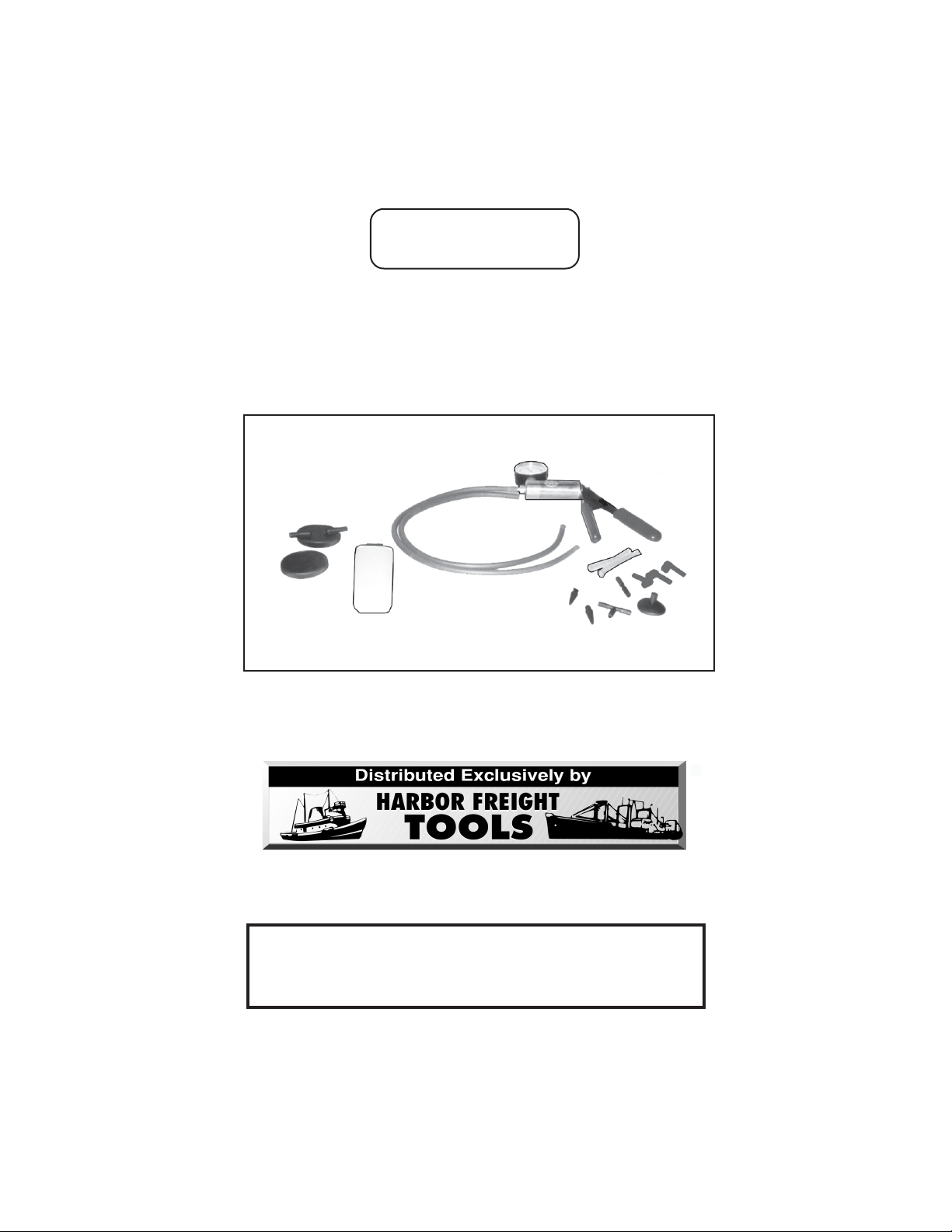
BRAKE BLEEDER & VACUUM PUMP KIT
®
Model 92474
ASSEMBLY AND OPERATING INSTRUCTIONS
3491 Mission Oaks Blvd., Camarillo, CA 93011
Visit our Web site at: http://www.harborfreight.com
TO PREVENT SERIOUS INJURY,
READ AND UNDERSTAND ALL WARNINGS
AND INSTRUCTIONS BEFORE USE.
Copyright 2004 by Harbor Freight Tools
manual or any artwork contained herein may be reproduced in any shape or form
For technical questions, or replacement parts, please call 1-800-444-3353.
©
without the express written consent of Harbor Freight Tools.
®
. All rights reserved. No portion of this
Page 2

PRODUCT SPECIFICATIONS
metInoitpircseD
eziSeguaGretemaiD"2
elacSeguaGmuucaV)gH/mc67>-<0(gH/ni03>-<0
seirosseccA
thgieWteNsdnuoP08.1
1
/
4
1
/
4
giartS
)2.ytQ(sdiLraJ
)2.ytQ(sretpadAesoHderepaT
)1.ytQ(rotcennoCesoH"T"
)1.ytQ(rotcennoCesoHth
)1.ytQ(retpadApuClasrevinU
)1.ytQ(raJriovreseR.zo4
)2.ytQ(sesoHmuucaVgnoL"32x.D.I"
)2.ytQ(sesoHmuucaVgnoL"3x.D.I"
)3.ytQ(sretpadAevlaVredeelBekarB
UNPACKING
When unpacking, check to make sure all the parts shown on the Parts List on page 9 are
included. If any parts are missing or broken, please call Harbor Freight Tools at the number shown on the cover of this manual as soon as possible.
SAVE THIS MANUAL
You will need this manual for the safety warnings and precautions, assembly, operating,
inspection, maintenance and cleaning procedures, parts list and assembly diagram. Keep
your invoice with this manual. Write the invoice number on the inside of the front cover.
Keep this manual and invoice in a safe and dry place for future reference.
GENERAL SAFETY RULES
WARNING!
READ AND UNDERSTAND ALL INSTRUCTIONS
Failure to follow all instructions listed below may
result in serious injury.
SAVE THESE INSTRUCTIONS
WORK AREA
1. Keep bystanders, children, and visitors away while operating the Brake
Bleeder/Vacuum Pump. Distractions can cause you to lose control. Protect
others in the work area from injury. Provide barriers or shields as needed.
SKU 92474 For technical questions, please call 1-800-444-3353. PAGE 2
Page 3

PERSONAL SAFETY
1. Stay alert. Watch what you are doing, and use common sense when operating the Brake Bleeder/Vacuum Pump. Do not use the tool while tired or under
the influence of drugs, alcohol, or medication. A moment of inattention while
operating the tool may result in serious personal injury.
2. Dress properly. Do not wear loose clothing or jewelry. Contain long hair.
Keep your hair, clothing, and jewelry away from moving parts. Loose clothes,
jewelry, or long hair can be caught in moving parts.
3. Do not overreach. Keep proper footing and balance at all times. Proper footing
and balance enables better control of the power tool in unexpected situations.
4. Use safety equipment. Always wear ANSI approved safety glasses underneath a
full face safety shield. Nonskid safety shoes, hard hat, or hearing protection must
be used for appropriate conditions.
TOOL USE AND CARE
1. Do not force the tool. Use the correct tool for your application. The correct tool
will do the job better and safer at the rate for which it is designed.
2. Store idle tools out of reach of children and other untrained persons. Tools
are dangerous in the hands of untrained users.
3. Maintain tools with care. Keep tools dry and clean. Properly maintained tools
are less likely to bind and are easier to control. Do not use a damaged tool. Tag
damaged tools “Do not use” until repaired.
4. Check for misalignment or binding of moving parts, breakage of parts, and
any other condition that may affect the tool’s operation. If damaged, have the
tool serviced before using. Many accidents are caused by poorly maintained
tools.
5. Use only accessories that are recommended by the manufacturer for your
model. Accessories that may be suitable for one tool may become hazardous
when used on another tool.
SERVICE
1. Tool service must be performed only by qualified repair personnel. Service or
maintenance performed by unqualified personnel could result in a risk of injury.
2. When servicing a tool, use only identical replacement parts. Follow instruc-
tions in the
Use of unauthorized parts or failure to follow maintenance instructions may create
a risk of injury.
“Inspection, Maintenance, And Cleaning”
section of this manual.
SKU 92474 For technical questions, please call 1-800-444-3353. PAGE 3
Page 4

SPECIFIC SAFETY RULES
1. Maintain a safe working environment. Keep the work area well lit. Make sure
there is adequate surrounding workspace. Always keep the work area free of obstructions, grease, oil, trash, and other debris. Do not use the Brake Bleeder/Vacuum
Pump in areas near flammable chemicals, dusts, and vapors. Do not use this product in a damp or wet location.
2. Maintain labels and nameplates on this product. These carry important information. If unreadable or missing, contact Harbor Freight Tools for a replacement.
3. Keep the Handles of the Brake Bleeder dry, clean, and free from brake fluid,
oil, and grease.
4. Prior to using the Brake Bleeder/Vacuum Pump make sure to read and understand all warnings, safety precautions, and instructions as outlined in the
vehicle
surement values for vacuum related readings. It is beyond the scope of this manual
to properly describe the correct procedure and test data for each vehicle.
5. WARNING! Carbon monoxide is produced while a vehicle’s engine is operat-
ing and is deadly in a closed environment. Early signs of carbon monoxide poisoning resemble the flu, with headaches, dizziness, or nausea. If you have these signs,
the work area may not be vented properly. Get fresh air immediately.
manufacturer’s instruction manual. Every vehicle has specific mea-
6. Prior to using the Brake Bleeder/Vacuum Pump, make sure to place the
vehicle’s transmission in “PARK” (if automatic) or “NEUTRAL” (if manual).
Then, block the tires with chocks.
7. Be alert for hot engine parts to avoid accidental burns.
8. Avoid accidental fire and/or explosion. Do not smoke near engine fuel and
battery components.
9. Use the Brake Bleeder only with brake fluid. Do not attempt to use the tool to
siphon any other liquids. Damage to the internal chamber and seal, or future brake
fluid contamination may result.
10. Follow guidelines for proper brake fluid disposal. Used brake fluid should be
removed from the vehicle and properly recycled. Many states require recycling.
Contact your local solid/liquid waste authority for information on recycling. Do not
reuse old brake fluid.
11. Brake fluid is corrosive. Avoid spilling it on the vehicle’s exterior, it can harm
automobile paint.
SKU 92474 For technical questions, please call 1-800-444-3353. PAGE 4
Page 5

11. WARNING! People with pacemakers should consult their physician(s) be-
fore using this product on a running engine. Electromagnetic fields in close proximity to a heart pacemaker could cause interference or failure of the pacemaker. In
addition, people with pacemakers should adhere to the following: Caution is necessary when near the coil, spark plug cables, or distributor of a running engine. The
engine should always be off if adjustments are to be made to the distributor.
12. WARNING! The brass components of this product contain lead, a chemical
known to the State of California to cause cancer and birth defects (or other reproductive harm). (California Health & Safety Code § 25249,
et seq.
)
13. WARNING! The warnings, precautions, and instructions discussed in this
manual cannot cover all possible conditions and situations that may occur. The
operator must understand that common sense and caution are factors which cannot be built into this product, but must be supplied by the operator.
ASSEMBLY AND OPERATING INSTRUCTIONS
To Bleed Brakes:
1. Attach a 3” Vacuum Hose (5) to the bottom of the Jar Lid (2a). (See Figure A.)
2. Attach a 23” Vacuum Hose (4) to the top of the Jar Lid (2a) marked “TO PUMP”.
Then, attach the other end of the 23” Vacuum Hose to the Brake Bleeder/Vacuum
Pump (1). (See Figure A.)
3. Firmly attach the Jar Lid (2a) to the Reservoir Jar (3). (See Figure A.)
4. Remove the cap from the vehicle’s master cylinder, and check to make sure the
23”
VACUUM
HOSE
(4)
VACUUM
HOSE
3”
(5)
JAR LID (2a)
GAUGE
23” VACUUM HOSE (4)
VACUUM
RELEASE
RESERVOIR JAR (3)
BRAKE BLEEDER SCREW ADAPTER (9)
CONTROL
BRAKE BLEEDER/
VACUUM PUMP
(1)
TO WHEEL CALIPER BLEEDER SCREW
FIGURE A
SKU 92474 For technical questions, please call 1-800-444-3353. PAGE 5
Page 6

master cylinder is full of brake fluid. If not full, fill the master cylinder to capacity with
clean, new brake fluid. (Use only the kind of brake fluid recommended by the vehicle manufacturer.)
6. NOTE: Determine the proper brake bleeding sequence from your vehicle service
manual (i.e., right rear wheel, left rear wheel, right front wheel, left front wheel).
7. Connect the 23” Vacuum Hose (4) to the remaining port on the Jar Lid (2a) and then
connect the other end to the Brake Bleeder Screw Adapter (9). (See Figure A.)
8. Squeeze the Handle of the Brake Bleeder/Vacuum Pump (1) 10 to 15 times to
create a vacuum in its Reservoir Jar (3). NOTE: The Gauge on the Brake Bleeder/
Vacuum Pump should read at approximately 10 in/Hg. Do not exceed 20 in/Hg. A
greater vacuum could damage the vehicle’s brake system. (See Figure A.)
9. Once the Brake Bleeder/Vacuum Pump (1) is ready, check for leaks at the Reservoir Jar (3) and at all Vacuum Hose (4, 5) connections. If there is a leak, release the
vacuum in the Brake Bleeder/Vacuum Pump with the Vacuum Release Control.
CAUTION! NEVER remove the Jar Lid (2a) before releasing the vacuum
in the Brake Bleeder/Vacuum Pump.
Correct the leak, and once again create a vacuum in the Brake Bleeder/Vacuum
Pump to approximately 10 in/Hg. (See Figure A.)
10. Open the vehicle’s wheel caliper bleeder screw, and allow brake fluid to flow into the
Reservoir Jar (3). Then, retighten the wheel caliper bleeder screw after bleeding.
(See Figure A.)
11. Release the vacuum in the Brake Bleeder/Vacuum Pump (1) with the Vacuum Release Control. Then, disconnect the Brake Bleeder Screw Adapter (9) from the
vehicle’s wheel caliper bleeder screw. (See Figure A.)
12. NOTE: When necessary, release the vacuum in the tool and empty its Reservoir
Jar (3) of old brake fluid. To assist in transport, this set includes a leak-resistant Lid
(2b) without hose connections. After the brake fluid is disposed of properly, resume
bleeding the brakes.
13. Remove the cap from the vehicle’s master cylinder, and refill the master cylinder
back to its normal capacity with clean, new brake fluid. Then, replace the cap on
the master cylinder.
14. Proceed to the vehicle’s next wheel, and perform the same steps as above.
SKU 92474 For technical questions, please call 1-800-444-3353. PAGE 6
Page 7

15. When finished using the Brake Bleeder/Vacuum Pump, clean the tool and store it in
a clean, dry location out of reach of children.
16. WARNING! Before driving the vehicle, carefully check for leaks and
test for proper brake operation.
INSPECTION, MAINTENANCE, AND CLEANING
1. WARNING! Always release the vacuum in the Brake Bleeder/Vacuum
Pump before performing any inspection, maintenance, or cleaning.
2. Before each use: Inspect the general condition of the Brake Bleeder/Vacuum
Pump. Check for misalignment or binding of moving parts, cracked or broken
parts, damaged Hoses, loose connections, and any other condition that may
affect its safe operation. If a problem occurs, have the problem corrected before
further use. Do not use damaged equipment.
3. When cleaning: Do not clean the Brake Bleeder/Vacuum Pump with cleaners or
other solvents not intended for use with plastic components. Use a clean cloth
and, if necessary, a mild detergent. Do not immerse the Brake Bleeder/Vacuum
Pump (1) component in any liquid.
4. When storing: Never store fluid in the Reservoir Jar (3) of the Brake Bleeder/
Vacuum Pump. Always dispose of excess fluid properly, according to federal,
state, and local guidelines. Always store the Brake Bleeder/Vacuum Pump in a
clean, dry location out of reach of children.
5. WARNING! All maintenance, service, or repairs not listed in this
manual are only to be attempted by a qualified service technician.
SKU 92474 For technical questions, please call 1-800-444-3353. PAGE 7
Page 8

PARTS LIST
traPnoitpircseD.ytQtraPnoitpircseD.ytQ
1pmuPmuucaV/redeelBekarB16retpadAesoHderepaT2
a2)noitareporof(diLraJ17rotcenno
b2)tropsnartrof(diLraJ18 rotcennoCesoHthgiartS1
3raJriovreseR19 retpadAwercSredeelBekarB3
4esoHmuucaV"32201retp
5esoHmuucaV"32
CesoH"T"1
adApuClasrevinU1
ASSEMBLY DIAGRAM
1
3
2a
2b
4
4
5
5
9
8
6
7
6
10
9
9
NOTE:
Some parts are listed and shown for illustration purposes only,
and are not available individually as replacement parts.
PLEASE READ THE FOLLOWING CAREFULLY
THE MANUFACTURER AND/OR DISTRIBUTOR HAS PROVIDED THE PARTS LIST AND
ASSEMBLY DIAGRAM IN THIS MANUAL AS A REFERENCE TOOL ONLY. NEITHER
THE MANUFACTURER OR DISTRIBUTOR MAKES ANY REPRESENTATION OR WARRANTY OF ANY KIND TO THE BUYER THAT HE OR SHE IS QUALIFIED TO MAKE ANY
REPAIRS TO THE PRODUCT, OR THAT HE OR SHE IS QUALIFIED TO REPLACE ANY
PARTS OF THE PRODUCT. IN FACT, THE MANUFACTURER AND/OR DISTRIBUTOR
EXPRESSLY STATES THAT ALL REPAIRS AND PARTS REPLACEMENTS SHOULD BE
UNDERTAKEN BY CERTIFIED AND LICENSED TECHNICIANS, AND NOT BY THE
BUYER. THE BUYER ASSUMES ALL RISK AND LIABILITY ARISING OUT OF HIS OR
HER REPAIRS TO THE ORIGINAL PRODUCT OR REPLACEMENT PARTS THERETO,
OR ARISING OUT OF HIS OR HER INSTALLATION OF REPLACEMENT PARTS
THERETO.
SKU 92474 For technical questions, please call 1-800-444-3353. PAGE 8
 Loading...