

Page 1
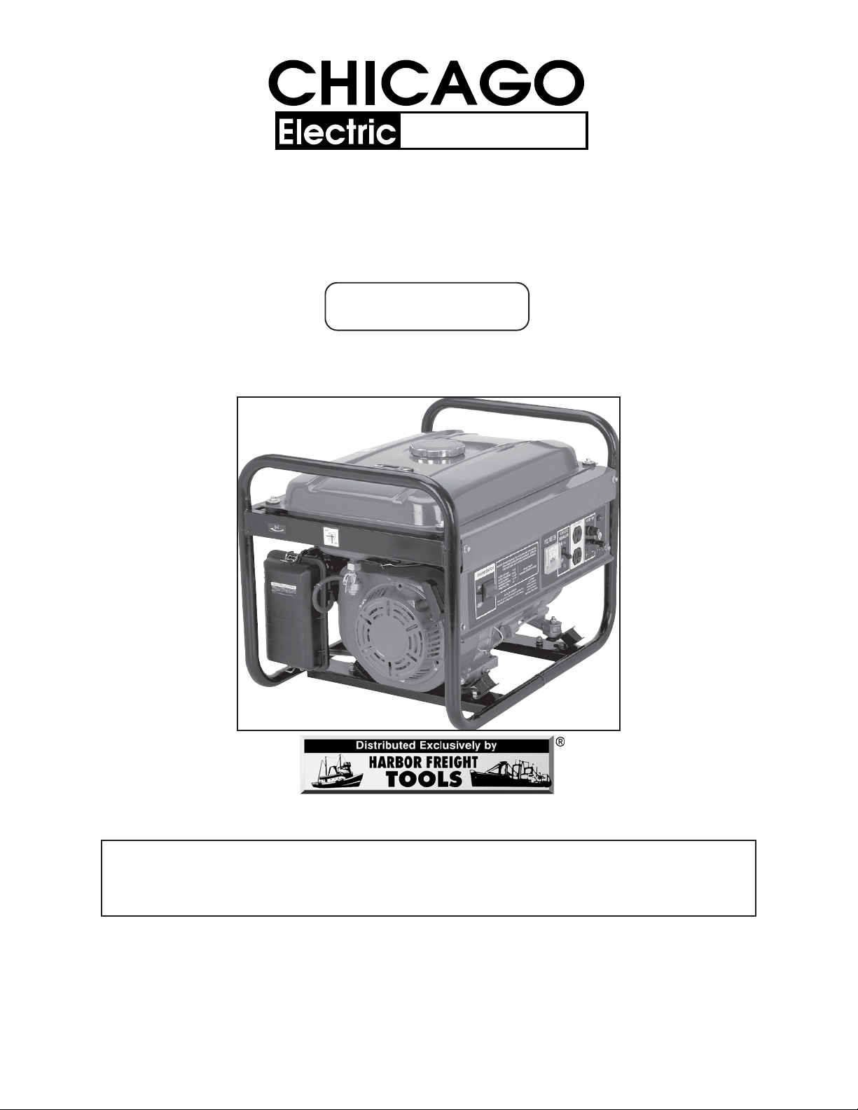
GENERATOR SET
Generators
5.5 HP - RECOIL START - 2200W/2400W RATED
Model 92455
OPERATING INSTRUCTIONS
3491 Mission Oaks Blvd., Camarillo, CA 93011
Visit our Web site at http://www.harborfreight.com
TO PREVENT SERIOUS INJURY OR DEATH,
READ AND UNDERSTAND ALL WARNINGS
AND INSTRUCTIONS BEFORE USE.
Copyright© 2004 by Harbor Freight Tools®. All rights reserved. No
portion of this manual or any artwork contained herein may be reproduced in
any shape or form without the express written consent of Harbor Freight Tools.
For technical questions and replacement parts, please call 1-800-444-3353
REV 03/06
Page 2
PRODUCT SPECIFICATIONS
Item Description
VAC Electrical
Specifications
VDC Electrical
Specifications
Voltmeter Equipped 0-150 Volts / 50 Volt Increments
Display Lights Red (Run)
Generator Type Brushless / Revolving Field / Self Exciting
Gasoline Engine 5.5 HP / Unleaded Gasoline Powered
Fuel Tank Capacity 3.96 Gallons (15 Liters) / Includes Fuel Gauge
Estimated Run Time 11.8 Continuous Running Hours
Weight 103.6 Pounds
115 Volts @ 19 Amps Current Output
60 Hz
Continuous/Rated Wattage: 2,200
Peak Wattage: 2,400
Two 115 VAC, 3-Prong Grounding Outlets
One 19 AMP Circuit Breaker
12 VDC @ 10 Amps Current Output
Two Pole / Single Phase
.
Recoil Start / 4-Cycle / OHV Air Cooled
163 CC Displacement / 3600 RPM
0.63 Quart (0.6 Liter) Oil Capacity
CARB and EPA Certified
This product requires oil and fuel to be added before starting.
Attempting to start the engine without oil WILL ruin the engine and
void the warranty.
Caution: This generator is not intended to power sensitive electronic
equipment without the addition of an appropriate line conditioner
(sold separately).
The Emission Control System for this generator’s engine is warranted
for standards set by the U.S. Environmental Protection Agency and by the
California Air Resources Board (also known as CARB). For warranty information, refer to the back two pages of this manual.
SAVE THIS MANUAL
You will need this manual for the safety warnings and precautions, operating, in-
spection, maintenance and cleaning procedures, parts list and assembly diagram. Keep
your invoice with this manual. Write the invoice number on the inside of the front cover.
Keep this manual and invoice in a safe and dry place for future reference.
SKU 92455 For technical questions, please call 1-800-444-3353. Page 2
Page 3
UNPACKING
When unpacking, check to make sure all the parts shown on the Parts Lists on
pages 18 and 20 are included. If any parts are missing or broken, please call Harbor
Freight Tools at the number shown on the cover of this manual as soon as possible.
GENERAL SAFETY RULES
WARNING!
READ AND UNDERSTAND ALL INSTRUCTIONS
Failure to follow all instructions listed below may result in
electric shock, fire, and/or serious injury.
SAVE THESE INSTRUCTIONS
WORK AREA
1. Keep your work area clean and well lit. Cluttered benches and dark areas invite
accidents.
2. Do not operate power tools in explosive atmospheres, such as in the pres-
ence of flammable liquids, gases, or dust. Generators create sparks which may
ignite the dust or fumes.
3. Keep bystanders, children, and visitors away while operating a generator.
Provide barriers or shields as needed.
ELECTRICAL SAFETY
4. Grounded tools must be plugged into an outlet properly installed and grounded
in accordance with all codes and ordinances. Never remove the grounding
prong or modify the plug in any way. Do not use any adapter plugs. Check
with a qualified electrician if you are in doubt as to whether the outlet is properly grounded. If the tools should electrically malfunction or break down, ground-
ing provides a low resistance path to carry electricity away from the user.
5. Double insulated tools are equipped with a polarized plug (one blade is wider
than the other). This plug will fit in a polarized outlet only one way. If the plug
does not fit fully in the outlet, reverse the plug. If it still does not fit, contact a
qualified electrician to install a polarized outlet. Do not change the plug in
any way. Double insulation eliminates the need for the three wire grounded
power cord and grounded power supply system.
SKU 92455 For technical questions, please call 1-800-444-3353. Page 3
Page 4

6. Avoid body contact with grounded surfaces such as pipes, radiators, ranges,
and refrigerators. There is an increased risk of electric shock if your body is
grounded.
7.
8. Do not abuse the Power Cords. Never use a Power Cord to carry tools or
pull the Plug from an outlet. Keep Power Cords away from heat, oil, sharp
edges, or moving parts. Replace damaged Power Cords immediately. Dam-
aged Power Cords increase the risk of electric shock.
9. When operating a power tool outside, use an outdoor extension cord
marked “W-A” or “W”. These extension cords are rated for outdoor use, and
reduce the risk of electric shock.
10. Stay alert. Watch what you are doing, and use common sense when operat-
ing a generator. Do not use a generator while tired or under the influence of
drugs, alcohol, or medication. A moment of inattention while operating genera-
tors may result in serious personal injury.
11. Dress properly. Do not wear loose clothing or jewelry. Contain long hair.
Keep your hair, clothing, and gloves away from moving parts. Loose clothes,
jewelry, or long hair can be caught in moving parts.
Do not expose power tools to rain or wet conditions. Water entering a
generator will increase the risk of electric shock.
PERSONAL SAFETY
12. Avoid accidental starting. Make sure the Power Switch is in its “OFF” posi-
tion, and disconnect the Spark Plug Wire when not in use.
13. Remove adjusting keys or wrenches before turning the generator on. A
wrench or a key that is left attached to a rotating part of the generator may result in
personal injury.
14. Do not overreach. Keep proper footing and balance at all times.
15. Use safety equipment. Always wear eye protection. Wear ANSI approved
safety impact eye goggles. Dust mask, nonskid safety shoes, hard hat, or hearing
protection must be used for appropriate conditions.
16. Do not force the generator. Use the correct generator for your application.
The correct generator will do the job better and safer at the rate for which it is
designed.
SKU 92455 For technical questions, please call 1-800-444-3353. Page 4
Page 5

17. Do not use the generator if the Power Switch does not turn it on or off. Any
generator that cannot be controlled with the Power Switch is dangerous and must
be replaced.
GENERATOR USE AND CARE
18. Make sure the Power Switch is in its “OFF” position and disconnect the
spark plug wire before making any adjustments, changing accessories, or
storing the generator. Such preventive safety measures reduce the risk of
starting the generator accidentally.
19. Store idle generators out of reach of children and other untrained persons.
Generators are dangerous in the hands of untrained users.
20. Maintain generators with care. Do not use a damaged generator. Tag damaged
generators “Do not use” until repaired.
21. Check for misalignment or binding of moving parts, breakage of parts, and
any other condition that may affect the generator’s operation. If damaged,
have the generator serviced before using. Many accidents are caused by
poorly maintained generators.
22. Use only accessories that are recommended by the manufacturer for your
model. Accessories that may be suitable for one generator may become hazardous when used on another generator.
SERVICE
23. Maintain labels and nameplates on the Generator and Engine. These carry
important information. If unreadable or missing, contact Harbor Freight Tools for a
replacement.
24. Generator service must be performed only by qualified repair personnel.
Service or maintenance performed by unqualified personnel could result in a risk
of injury.
25. When servicing a generator, use only identical replacement parts. Follow
instructions in the
manual. Use of unauthorized parts or failure to follow maintenance instructions
may create a risk of electric shock or injury.
“Inspection, Maintenance, And Cleaning”
section of this
SKU 92455 For technical questions, please call 1-800-444-3353. Page 5
Page 6

SPECIFIC PRODUCT WARNINGS AND PRECAUTIONS
HEART PACEMAKER PRECAUTION
1. WARNING! People with pacemakers should consult their physician(s)
before using this product. Electromagnetic fields in close proximity to a heart
pacemaker could cause interference to or failure of the pacemaker.
INSTALLATION PRECAUTIONS
1. Ensure installation meets all applicable safety, and local and national electrical
codes. Have installation performed by a qualified, licensed electrician and building contractor.
2. All electrical work, including the earth-ground connection, should be completed by
a licensed electrician.
3. Any separate fuel storage Generator supply facility must be built or installed in full
compliance with all relevant local, state, and federal regulations.
4.
5. If the generator is installed outdoors, it must be weatherproofed and should be soundproofed. It should not be run outdoors without protection to the Generator and wiring conduit.
6. Never lift the Generator using the engine or alternator lifting lugs. Connect lifting
equipment to the Frame of the Generator.
7. Before lifting the Generator, ensure the lift rigging and supporting structure are in
good condition, and are rated to lift such a load.
8. Keep all personnel away from the suspended generator while relocating.
9. The supporting floor/ground surface should be level, and strong enough to safely
hold the weight of the Generator. If the floor/ground surface is not level, strong cross
members should be placed under the full length of the Generator Frame at its low
side.
If the generator is installed indoors, exhaust fumes must be piped out of the
building using leak-free, heat-resistant piping. Use the Generator only in
well ventilated outdoor areas. Carbon monoxide fumes are a colorless,
odorless gas that, if inhaled, can cause serious injury or death. Pipes
and silencer should not use any flammable materials, nor should they be
installed near the same. Generator exhaust fumes must be within legal limits.
SKU 92455 For technical questions, please call 1-800-444-3353. Page 6
Page 7

10. For trailer installation, the Generator should be mounted on the center point of the
trailer, over the wheels.
11. Install sound and weather proofing only when it is not raining or snowing to avoid
trapping moisture within the Generator’s area.
FIRE AND EXPLOSION PRECAUTIONS
1. Gasoline fuel and fumes are flammable, and potentially explosive. Use proper
fuel storage and handling procedures. Always have multiple ABC class fire
extinguishers nearby.
2. Keep the Generator and surrounding area clean at all times.
3. When spills of fuel or oil occur, they must be cleaned up immediately. Dispose of
fluids and cleaning materials as per any local, state, or federal codes and regulations. Store oil rags in a covered metal container.
4. Never store fuel or other flammable materials near the Generator.
5. Do not smoke, or allow sparks, flames or other sources of ignition around the
Engine and Fuel Tank. Fuel vapors are explosive.
6. Keep grounded conductive objects, such as tools, away from exposed, live
electrical parts and connections to avoid sparking or arcing. These events could
ignite fumes or vapors.
7. Do not refill the Fuel Tank while the Engine is running or while the Engine is still
hot. Do not operate the Generator with known leaks in the fuel system.
8. Excessive buildup of unburned fuel gases in the exhaust system can create a
potentially explosive condition. This buildup can occur after repeated failed start
attempts, valve testing, or hot engine shutdown. If this occurs, open exhaust
system drain plugs, if equipped, and allow the gases to dissipate before attempting to restart the Generator.
9. Use only engine manufacturer recommended fuel and oil.
SKU 92455 For technical questions, please call 1-800-444-3353. Page 7
Page 8

MECHANICAL PRECAUTIONS
1. ALWAYS make sure the Power Switch is in its “OFF” position. Disconnect the
spark plug wire, and allow the Engine to completely cool before carrying out
maintenance.
2. Check for damaged parts. Before using the Generator, any part that appears
damaged should be carefully checked to determine that it will operate properly
and perform its intended function. Check for alignment and binding of moving
parts, any broken parts or mounting fixtures, and any other condition that may
affect proper operation. Any part that is damaged should be properly repaired or
replaced by a qualified technician.
3. The Generator is designed with guards for protection from moving parts. In any
case, care must still be taken to protect personnel and equipment from other
mechanical hazards when working around the generator.
4. Do not operate the Generator with safety guards removed. While the Generator is
running, do not attempt to reach around the safety guards for maintenance or any
other reason.
5. Keep hands, arms, long hair, loose clothing, and jewelry away from moving parts.
Be aware that when engine parts are moving fast they cannot be seen clearly.
6. Keep access doors on enclosures closed and locked when access is not required.
7. When working on or around the Generator always wear protective clothing including ANSI approved safety gloves, safety eye goggles, and safety hat.
8. Do not alter or adjust any part of the Generator that is assembled and supplied by
the manufacturer.
9. Always follow and complete scheduled Engine and Generator maintenance.
CHEMICAL PRECAUTIONS
1. Avoid contact with hot fuel, oil, exhaust fumes, and solid surfaces.
2. Avoid body contact with fuels, oils, and lubricants used in the Generator. If
swallowed, seek medical treatment immediately. Do not induce vomiting if fuel is
swallowed. For skin contact, immediately wash with soap and water. For eye
contact, immediately flush eyes with clean water.
SKU 92455 For technical questions, please call 1-800-444-3353. Page 8
Page 9
NOISE PRECAUTIONS
(
)
1. Prolonged exposure to noise levels above 85 dBA is hazardous to hearing.
Always wear ANSI approved ear protection when operating or working around
the Generator when it is running.
ELECTRICAL PRECAUTIONS
1. All connections and conduits from the Generator to the load must only be installed by trained and licensed electricians, and in compliance with all relevant
local, state, and federal electrical codes and standards, and other regulations
where applicable.
2. The Generator must be earth-grounded in accordance with all relevant electrical
codes and standards before operation.
®
3. If an extension cord (not included) is used, make sure to use only UL
approved
cords having the correct gauge and length. (See Figure A.)
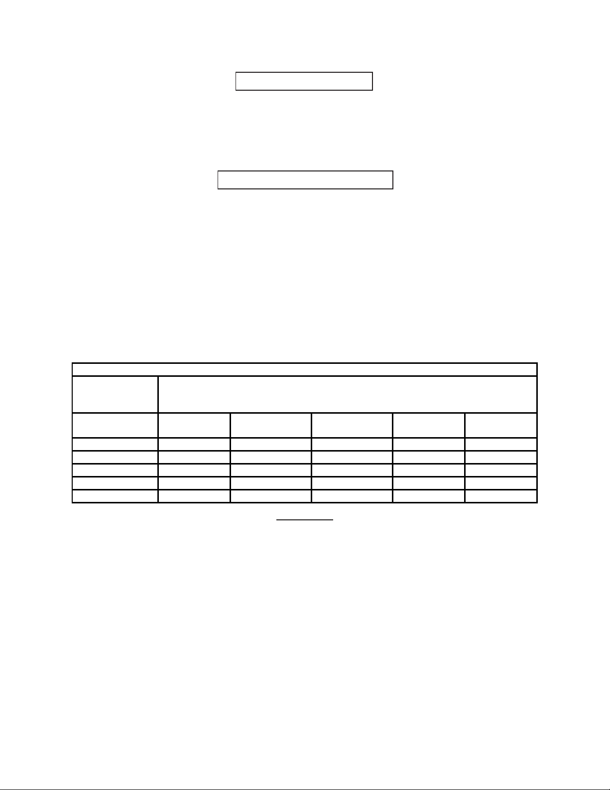
REQUIRED MINIMUM EXTENSION CORD GAUGE – 120 VOLT
NAMEPLATE
AMPERES
At Full Load
0 - 25
Feet
0 - 5 16 16 16 12 12
5.1 - 8 16 16 14 10 -
8.1 - 12 14 14 12 - -
12.1 - 15 12 12 10 - -
15.1 - 20 10 10 10 - -
EXTENSION CORD LENGTH
25 - 50
Feet
50 -100
Feet
100 – 150
Feet
150– 200
Feet
FIGURE A
4. Do not attempt to connect or disconnect load connections while standing in
water, or on wet or soggy ground.
5. Do not touch electrically energized parts of the Generator and interconnecting
cables or conductors with any part of the body, or with any non-insulated
conductive object.
6. Connect the generator only to a load or electrical system (115 volt) that is compatible with the electrical characteristics and rated capacities of the Generator.
7. Before servicing equipment powered by the Generator, disconnect the equipment
from its power input.
SKU 92455 For technical questions, please call 1-800-444-3353. Page 9
Page 10

8. Keep all electrical equipment clean and dry. Replace any wiring where the insulation is cracked, cut, abraded or otherwise degraded. Replace terminals that are
worn, discolored, or corroded. Keep terminals clean and tight.
9. Insulate all connections and disconnected wires.
10. Guard against electric shock. Prevent body contact with grounded surfaces such
as pipes, radiators, ranges, and refrigerator enclosures.
11. Use only Class BC or Class ABC fire extinguishers on electrical fires.
INSTALLATION
1. NOTE: Prior to powering tools and equipment, make sure the Generator’s rated
voltage, wattage, and amperage capacity (115 V - 20 AMPs) is adequate to supply all electrical loads that the unit will power. If powering exceeds the
Generator’s capacity, it may be necessary to group one or more of the tools and/or
equipment for connection to a separate Generator.
2. Electrical and other permits may be required for the installation of emergency
power systems. Investigate the local building and electrical codes before installing this unit. Installation must be completed by licensed contractors.
3. WARNING! The Generator weighs 103.6 pounds. Use care and the proper
lifting or hoisting equipment when moving it to the installation location. Always
connect hoist lines to the Frame (41) of the Generator.
GENERAL LOCATION
1. It is recommended to locate and install the Generator outdoors where cooling air
is readily available.
2. Install the Generator so that the air inlets and outlets are not blocked by obstructions such as bushes, trees, or snow drifts. Locating it in the path of heavy winds
or snowdrifts may require the placement of a barrier for protection. The air inlet,
in normal weather conditions, should face the prevailing wind direction.
3. Install the Generator on a concrete slab or other area where rain drainage or
flood waters can not reach it.
4. Generator placement should allow four feet of access to all sides for maintenance.
SKU 92455 For technical questions, please call 1-800-444-3353. Page 10
Page 11

5. Place the Generator as close as possible to the electrical tools and equipment
being powered to reduce the length of extension cords.
6. If the Generator in located indoors the Engine exhaust must be ventilated to the
outdoors using leakproof, heat resistant, flexible, metal, flex tubing.
GENERATOR SUPPORT AND MOUNTING
1. Mount the Generator on a concrete slab capable of supporting the weight of the
Generator. The slab must extend on all sides beyond the Frame (41) by at least
one foot. Contact a cement contractor for slab specifications if necessary. Attach
the Frame to the concrete slab using 3/8” diameter expansion anchor bolts (not
supplied).
GROUNDING THE GENERATOR
1. NOTE: It is recommended that only a trained and licensed electrician perform
this procedure.
2. Connect a #6 AWG grounding wire (not included) from the Ground Connector (8)
on the Generator to a grounding rod (not included) that has been driven at least
24 inches deep into the earth. The grounding rod must be an earth-driven copper or brass rod (electrode) which can adequately ground the Generator.
(See Figure B, next page.)
OPERATING INSTRUCTIONS
NOTE: For additional references to the parts listed in the following pages, refer to the
Assembly Diagrams on pages 19 and 21.
Pre-Start Checks:
1. Check to make sure the Engine’s Power Switch (2) is in its “OFF” position.
(See Figure B, next page.)
2. IMPORTANT! Prior to first using the Generator, the Engine MUST be filled
with approximately 3/4 (0.63) quart of a high quality SAE 10W-30 grade
engine oil. To do so, unscrew and remove the Engine’s Oil Dipstick (65A) lo-
cated at the bottom of the Engine Crankcase. Fill the Engine’s Crankcase until
the oil level is level with the upper marked line on the Dipstick. Then, screw the
Dipstick back into the Oil Fill Hole. (See Figure C, next page.)
SKU 92455 For technical questions, please call 1-800-444-3353. Page 11
Page 12
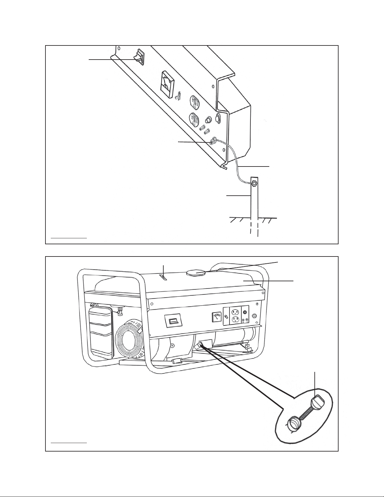
ENGINE
POWER
SWITCH
(2)
GROUND CONNECTOR
(8)
#6 AWG
GROUNDING WIRE
(NOT INCLUDED)
GROUNDING ROD
(NOT INCLUDED)
FIGURE B
FUEL GAUGE (34)
FUEL TANK CAP
(33)
FUEL TANK
(30)
OIL DIPSTICK
(65A)
FIGURE C
SKU 92455 For technical questions, please call 1-800-444-3353. Page 12
Page 13
3. Before the first use, remove the Fuel Tank Cap (33) and fill the Fuel Tank (30)
with unleaded gasoline. Then, replace the Fuel Tank Cap. Thereafter, check the
Engine’s Fuel Gauge (34) for the amount of unleaded gasoline in the Fuel Tank.
If necessary, refill the Fuel Tank with unleaded gasoline. (See Figure C.)
To Start The Engine:
1. Make sure the electrical powered tools/equipment that will be used is not
plugged in to the Generator.
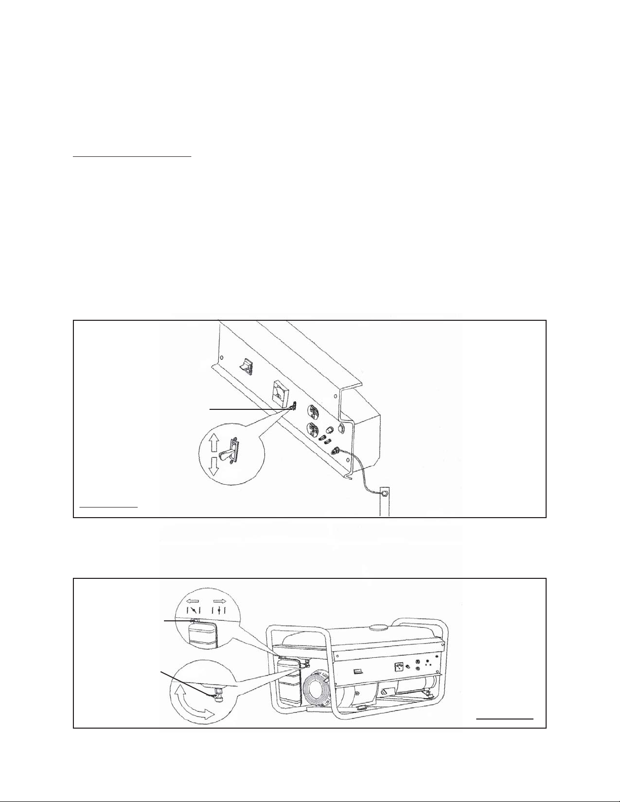
2. Turn the 115 volt AC Circuit Breaker (5) to its “ON” position. (See Figure D.)
3. Turn on the Fuel Valve (40). (See Figure E.)
4. Close the Choke Lever (21A) to about 1/8” clearance. (See Figure E.)
CIRCUIT BREAKER
FIGURE D
CLOSED OPEN
CHOKE LEVER
(21A)
FUEL VALVE (40)
(5)
ON
OFF
OFF
ON
FIGURE E
REV 03/06
SKU 92455 For technical questions, please call 1-800-444-3353. Page 13
Page 14
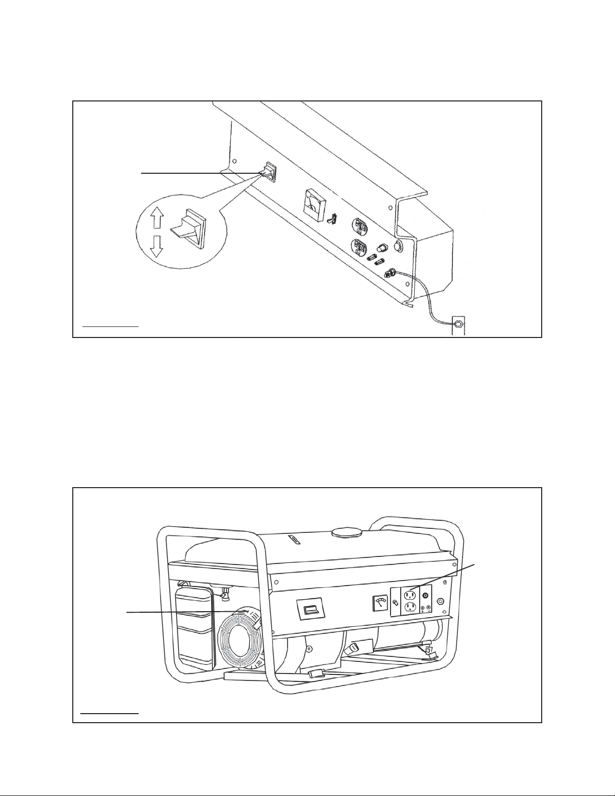
5. Turn the Engine Power Switch (2) to its “ON” position. (See Figure F.)
ENGINE
POWER
SWITCH
(2)
ON
OFF
FIGURE F
6. Hold the Start Handle (41A) loosely and pull it slowly several times to allow the
gasoline to flow into the Engine’s carburetor. Then hold the Start Handle firmly
and pull the rope hard and fast. Pull the rope all the way out, using two hands if
necessary. If necessary pull the rope several times until the Engine starts.
FUEL TANK (32)
(See Figure G.)
7. Allow the Engine to run for several seconds. Then, open the Choke Lever (21A)
all the way. (See Figure E.)
120 VOLT
DUEL
OUTLETS
(6)
START
HANDLE
(41A)
FIGURE G
SKU 92455 For technical questions, please call 1-800-444-3353. Page 14
Page 15

Powering 120 Volt AC Tools And Equipment:
1. Prior to powering tools and equipment, make sure the Generator’s rated voltage,
and amperage capacity (115 VAC / 20 AMPs) is adequate to supply all electrical
loads that the unit will power. If powering exceeds the Generator’s capacity, it
may be necessary to group one or more of the tools and/or equipment for connection to a separate generator.
2. Once the Generator is running, simply connect the Power Cords of 115 volt AC
powered tools and equipment into the 115 volt AC Duel Outlets (6).
(See Figure G.)
3. NOTE: The Generator features an AC Non-Fuse Circuit Breaker (5) to protect the
AC circuit in case of an overload. Should an overload occur the Breaker will “trip”
to its “OFF” position, causing the Generator to automatically shut down. In this
case, refer to Step #1 above in this section. Then, reset the circuitry system by
turning the Circuit Breaker to its “ON” position. Restart the Generator and continue powering the remaining tools and equipment. (See Figure D.)
4. When finished using the Generator, turn the Engine Power Switch (2) to its
“OFF” position. Turn the Fuel Valve (40) to its “OFF” position. Then, disconnect
all electrical powered tools and equipment from the Generator’s 115 volt AC Duel
Outlets (6). (See Figures E, F, and G.)
5. After the Engine and Generator have completely cooled, store the Generator in a
safe, clean, dry location (if not already installed in one).
Powering 12 Volt DC Tools And Equipment:
1. Prior to powering a tool or equipment, make sure the Generator’s rated voltage,
and amperage capacity (12 VDC / 10 AMPs) is adequate to supply all electrical
loads that the unit will power. If powering exceeds the Generator’s capacity, it
may be necessary to group one or more of the tools and/or equipment for connection to a separate generator.
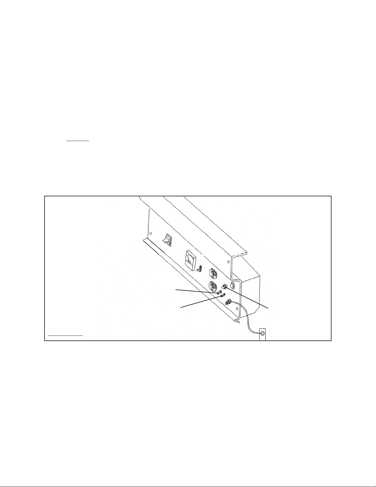
2. Connect the Power Cord of a 12 VDC powered tool or equipment to the DC
Terminals (7). NOTE: Make sure to connect the positive (+) lead of the Power
Cord to the positive (+) Terminal on the Generator, and connect the negative (-)
lead of the Power Cord to the negative (-) Terminal on the Generator.
(See Figure H, next page.)
3. If using
(5) to its “OFF” position. (See Figure D.)
only
a 12 volt DC tool or equipment, turn the 120 volt AC Circuit Breaker
SKU 92455 For technical questions, please call 1-800-444-3353. Page 15
Page 16
4. Start and run the Engine as previously discussed in this manual.
5. When finished using the Generator, turn the Engine Power Switch (2) to its
“OFF” position. Turn the Fuel Valve (40) to its “OFF” position. Then, discon-
nect the electrical powered tool or equipment from the Generator’s DC Terminals
(7). (See Figure H.)
6. After the Engine and Generator have completely cooled, store the Generator in a
safe, clean, dry location (if not already installed in one).
7.
NOTE: The Generator features a 10 AMP DC Fuse (9) to protect the DC circuit in
case of an overload. Should an overload occur the Fuse will burn out, causing
the Generator to automatically shut down. In this case, refer to Step #1 in this
section. Then, reset the circuitry system by replacing the burnt Fuse with a new
10 AMP DC Fuse. Restart the Generator and continue powering the remaining
tool or equipment. (See Figure H.)
POSITIVE (+) DC TERMINAL (7)
10 AMP
NEGATIVE (-) DC TERMINAL (7)
DC FUSE
(9)
FIGURE H
SKU 92455 For technical questions, please call 1-800-444-3353. Page 16
Page 17
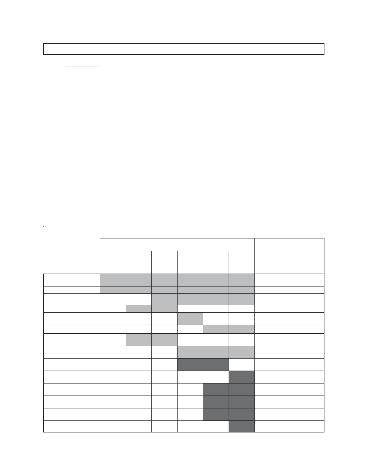
INSPECTION, CLEANING, AND MAINTENANCE
1. CAUTION! Always make sure the Engine Power Switch (2) is in its “OFF” position. Disconnect the spark plug wire from the engine and allow sufficient time
for the Engine and Generator to completely cool before performing any inspection, maintenance, or cleaning.
2. Before each use, inspect the general condition of the Generator. Check for loose
screws, misalignment or binding of moving parts, cracked or broken parts, damaged electrical wiring, and any other condition that may affect its safe operation. If
abnormal noise or vibration occurs, have the problem corrected before further use.
Do not use damaged equipment.
3. Follow all maintenance procedures as outlined in the Engine Maintenance Schedule below at the specified intervals. In addition, observe the following details:
Before each use: check to make sure the Engine’s oil level is adequate. If neces-
sary, fill the Engine’s Crankcase until the oil level is even with the Oil Fill Hole.
Before each use: with a soft brush, cloth, or vacuum, remove all debris from the
Generator and engine. Then, use a premium quality, lightweight machine oil to
lubricate all moving parts.
After the initial 20 hours of use and every 100 hours of use thereafter: drain the
old Engine oil and replace with approximately 3/4 (0.63) quart of a high quality SAE
10W-30 grade engine oil.
eludehcSecnanetniaMenignE
*lavretnI
sruoh8
ro
,yliad
esuerofeb
kcehcdnaenignenaelC
stun&stlob
lioenignelliferdnakcehC
*lioenigneegnahC
)A82(gulpkrapsnaelC
krapstsujdadnanaelC
sedortcele)A82(gulp
)A82(gulpkrapsecalpeR
tnemelerenaelcrianaelC
)A91(
renaelcriaecalpeR
)A91(tnemele
leufecalper/naelC
*)s(retlif
dnasenilleufecalpeR
*)s(retlif
morfnobracevomeR
*)A11(daehrednilyc
evlavtsujdadnakcehC
*ecnaraelc
tsujdadnanaelC
*roterubrac
*enigneluahrevO
sruoh05
ro
ylkeew
sruoh001
ro
ylkeewib
sruoh002
ro
ylhtnom
sruoh005
ro
6yreve
shtnom
.snoitidnocerevesroytsudniyrasseceneblliwecnanetniamtneuqerferoM*
sruoh0001
ro
ylraey
CINAHCEMYLNO
CINAHCEMYLNO
CINAHCEMYLNO
CINAHCEMYLNO
CINAHCEMYLNO
CINAHCEMYLNO
sliateD
retfayletaidemmiegnahclaitinI*
doirepni-kaerbruoh02
/NAICINHCETDEIFILAUQ*
/NAICINHCETDEIFILAUQ*
/NAICINHCETDEIFILAUQ*
/NAICINHCETDEIFILAUQ*
/NAICINHCETDEIFILAUQ*
/NAICINHCETDEIFILAUQ*
SKU 92455 For technical questions, please call 1-800-444-3353. Page 17
Page 18
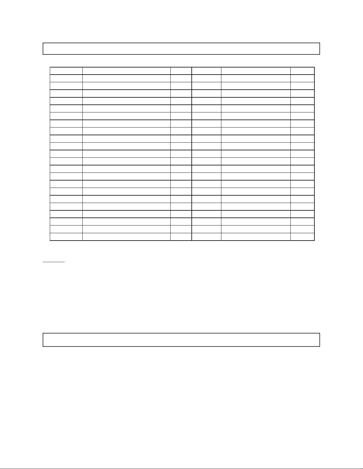
PARTS LIST
Part # Description Qty. Part # Description Qty.
1 Bolt (M6 x 12) w/Lock Washer 9 22 Bolt (M6 x 172) 4
2 Engine Power Switch 1 23 Bolt (M5 x 20) 4
3 Control Panel 1 24 Connection Board 1
4 Voltmeter 1 25 Nut (M5) 4
5 Circuit Breaker 1 26 Stator 1
6 Outlet 2 27 Rotor 1
7 DC Terminal 2 28 Cooling Fan 1
8 Ground Connector 1 29 Heat Insulation Board 1
9 DC Fuse 1 30 Fuel Tank 1
10 Pilot Light 1 31 Fuel Filter 1
11 Shock Absorber 4 32 Seal Ring 1
12 Shock Absorber Foot 4 33 Fuel Tank Cap 1
13 Lock Washer Nut 4 34 Fuel Gauge 1
14 Stator Cover 1 35 Bolt (M6 x 12) 2
15 Alternator Back Cover 1 36 Lock Washer Bolt (M6x12) 4
16 Capacitor 1 37 Spacer 4
17 Bolt (M5 x16) 4 38 Rub Washer 4
18 Rectifier 1 39 Bush 4
19 Bolt (M5x16) 3 40 Fuel Valve 1
20 Cable Sheath 1 41 Frame 1
21 Bolt (M8 x 242) 1 42 Switch Box Cover 1
43 Engine 1
NOTE: Some parts are listed and shown for illustration purposes only, and are not
available individually as replacement parts.
PLEASE READ THE FOLLOWING CAREFULLY
THE MANUFACTURER AND/OR DISTRIBUTOR HAS PROVIDED THE PARTS LIST AND ASSEMBLY
DIAGRAM IN THIS MANUAL AS A REFERENCE TOOL ONLY. NEITHER THE MANUFACTURER OR
DISTRIBUTOR MAKES ANY REPRESENTATION OR WARRANTY OF ANY KIND TO THE BUYER THAT
HE OR SHE IS QUALIFIED TO MAKE ANY REPAIRS TO THE PRODUCT, OR THAT HE OR SHE IS
QUALIFIED TO REPLACE ANY PARTS OF THE PRODUCT. IN FACT, THE MANUFACTURER AND/OR
DISTRIBUTOR EXPRESSLY STATES THAT ALL REPAIRS AND PARTS REPLACEMENTS SHOULD BE
UNDERTAKEN BY CERTIFIED AND LICENSED TECHNICIANS, AND NOT BY THE BUYER. THE BUYER
ASSUMES ALL RISK AND LIABILITY ARISING OUT OF HIS OR HER REPAIRS TO THE ORIGINAL
PRODUCT OR REPLACEMENT PARTS THERETO, OR ARISING OUT OF HIS OR HER INSTALLATION
OF REPLACEMENT PARTS THERETO.
SKU 92455 For technical questions, please call 1-800-444-3353. Page 18
Page 19
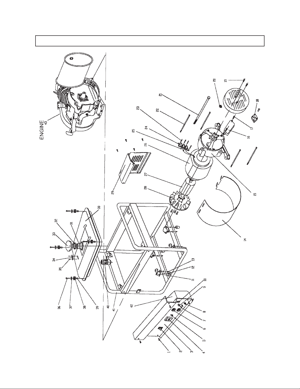
ASSEMBLY DIAGRAM
SKU 92455 For technical questions, please call 1-800-444-3353. Page 19
Page 20

PARTS LIST - CONTINUED
Part # Description Qty. Part # Description Qty.
1A Muffler 1 42A Starting Case Assy. 1
2A Cylinder Head Bolt 4 43A Spiral Spring 1
3A Cylinder Head Cover Bolt 4 44A Starting Wheel 1
4A Cylinder Head Cover 1 45A C-clip 1
5A Lock Nut 2 46A Starting Ratchet 2
6A Adjusting Screw 2 47A Friction Plate Screw 1
7A Rocker Arm 3 48A Cover 1
8A Rocker Arm Bolt 2 49A Starter Pulley 1
9A Valve Push Rod Guiding Board 1 50A Cooling Fan 1
10A Valve Push Rod 2 51A Flywheel Magneto 1
11A Cylinder Head 1 52A Cylinder Block 1
12A Carburetor Shield 1 53A Speed Control Lever 1
13A Carburetor Packing I 1 54A Governor Arm 1
14A Carburetor Assembly 1 55A Governor Spring 1
15A Air Cleaner Case 1 56A Governor Support 1
16A Air Cleaner Seal 1 57A Bolt (M6 x 15) 2
17A Bolt (M6) 4 58A Oil Alert Nut 1
18A Air Cleaner Cover 1 59A Plug (M10 x 15) 2
19A Air Cleaner Element 1 60A Plug Washer 2
20A Air Cleaner Separator 1 61A Oil Alert 1
21A Choke Lever 1 62A Bolt (M6) 2
22A Carburetor Packing II 1 63A Crankshaft 1
23A Stud Bolt (M6 x 109) 2 64A Crankshaft Gear 1
24A Intake Valve 1 65A Oil Dipstick 2
25A Exhaust Valve 1 66A Oil Dipstick Seal Ring 2
26A Cylinder Head Gasket 1 67A Gear Casing 1
27A Exhaust Pipe Stud 2 68A Bolt (M8 x 35) 6
28A Spark Plug 1 69A Gear Case Packing 2
29A Valve Guide 2 70A Bearing 2
30A Valve Spring 2 71A Camshaft Assy. 1
31A Rocker Shaft C-clip 2 72A Locating Pin 4
32A Anti-Wear Valve Stem Protector 2 73A Oil Seal 2
33A Cylinder Head Cover Packing 1 74A Connecting Rod Bolt 2
34A Governor Spring 1 75A Connecting Rod Cap 1
35A Bolt 1 76A Connecting Rod 1
36A High Tension Line 1 77A Piston 1
37A Ignition Coil 1 78A Compression Ring I 1
38A Nut (Special 14mm) 1 79A Compression Ring II 1
39A Starter Ratchet Spring 2 80A Oil Scraper Ring 1
40A Start Rope 1 81A Piston Pin 1
41A Start Handle 1 82A Piston Pin C-clip 2
NOTE: Some parts are listed and shown for illustration purposes only, and are not
available individually as replacement parts.
SKU 92455 For technical questions, please call 1-800-444-3353. Page 20
Page 21
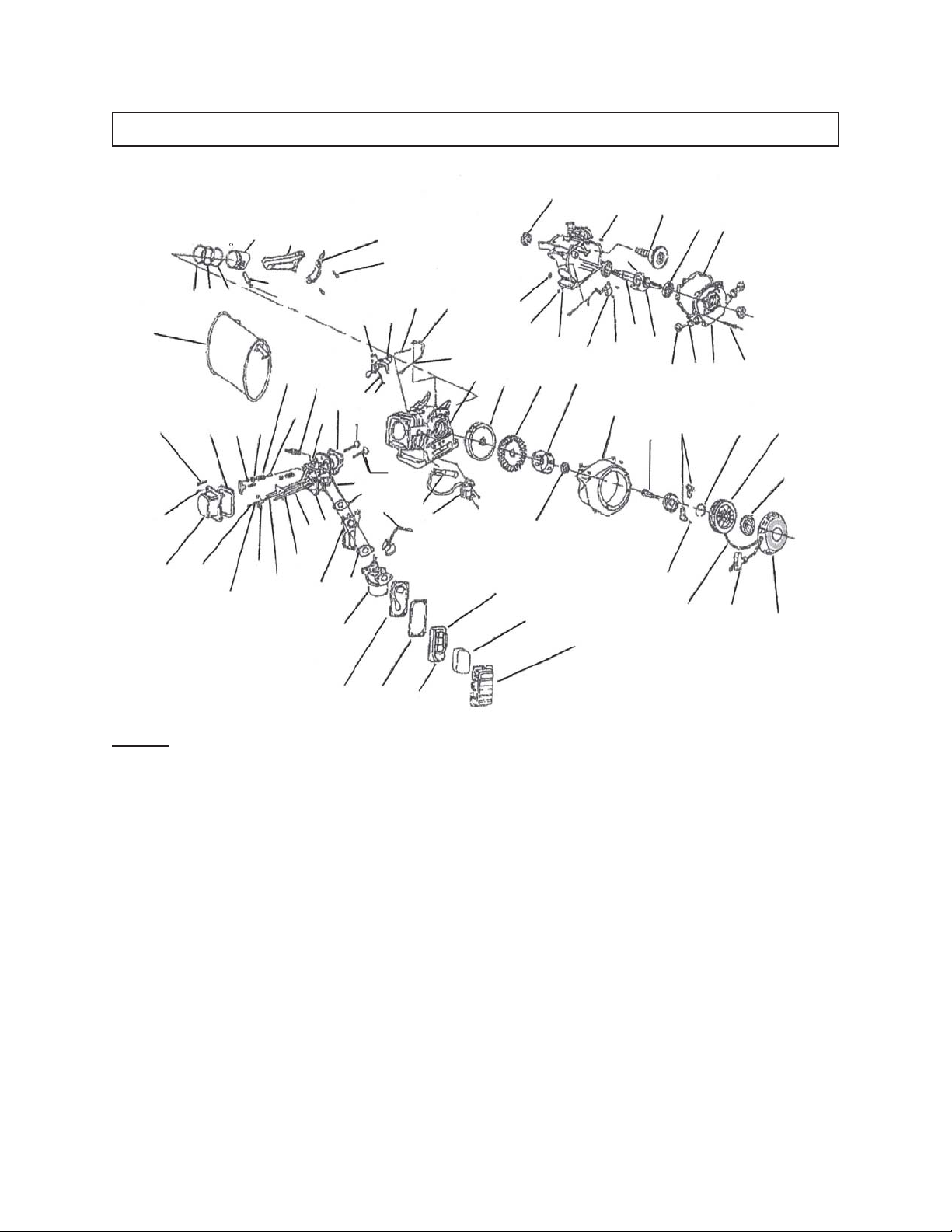
ASSEMBLY DIAGRAM - CONTINUED
1A
2A
3A
4A 5A
78A 79A 80A
32A
33A
6A
77A
31A
7A
76A
81A
82A
30A
8A
29A
10A
9A
28A
27A
11A
12A
17A
26A
13A
14A
57A
25A
23A
35A
22A
21A
75A
74A
56A
24A
36A
54A55A
37A
53A
52A
58A
51A
20A
59A
50A
38A
19A
73A
60A
61A
49A
18A
72A
62A
48A
63A
47A
71A
64A
65A
39A
66A
46A
40A
70A
67A
41A
69A
68A
44A45A
43A
42A
15A 16A
17A
NOTE: Some parts are listed and shown for illustration purposes only, and are not
available individually as replacement parts.
SKU 92455 For technical questions, please call 1-800-444-3353. Page 21
Page 22
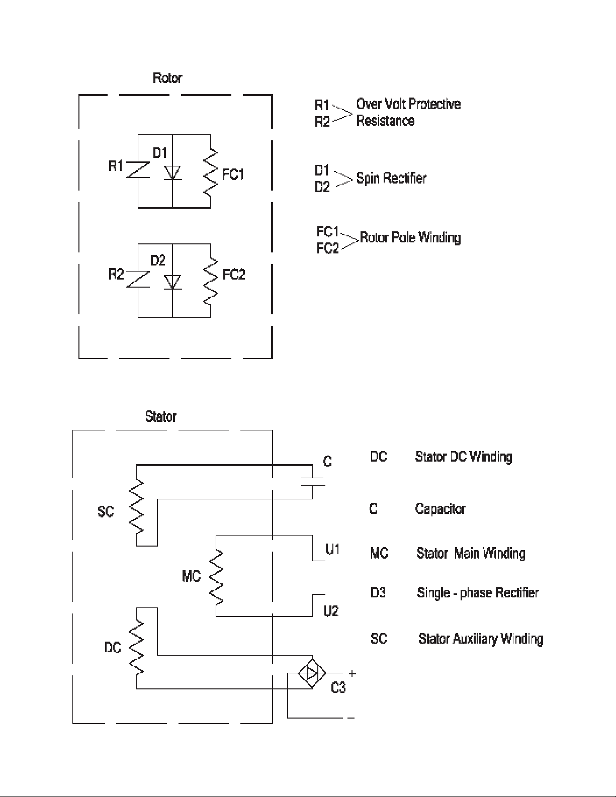
WIRING DIAGRAM
SKU 92455 For technical questions, please call 1-800-444-3353. Page 22
Page 23
Harbor Freight Tools Co. makes every effort to assure that its products meet high quality and durability
standards, and warrants to the original purchaser that this product is free from defects in materials and
workmanship for the period of one year from the date of purchase (90 days if used by a professional
contractor or if used as rental equipment). This warranty does not apply to damage due directly or
indirectly, to misuse, abuse, negligence or accidents, repairs or alterations outside our facilities, or to lack
of maintenance. We shall in no event be liable for death, injuries to persons or property, or for incidental,
contingent, special or consequential damages arising from the use of our product. Some states do not
allow the exclusion or limitation of incidental or consequential damages, so the above limitation of exclusion
may not apply to you.
To take advantage of this warranty, the product or part must be returned to us with transportation charges
prepaid. Proof of purchase date and an explanation of the complaint must accompany the merchandise.
If our inspection verifies the defect, we will either repair or replace the product at our election or we may
elect to refund the purchase price if we cannot readily and quickly provide you with a replacement. We
will return repaired products at our expense, but if we determine there is no defect, or that the defect
resulted from causes not within the scope of our warranty, then you must bear the cost of returning the
product.
This warranty gives you specific legal rights and you may also have other rights which vary from state to
state.
3491 Mission Oaks Blvd. • PO Box 6009 • Camarillo, CA 93011 • (800) 444-33533491 Mission Oaks Blvd. • PO Box 6009 • Camarillo, CA 93011 • (800) 444-3353
3491 Mission Oaks Blvd. • PO Box 6009 • Camarillo, CA 93011 • (800) 444-3353
3491 Mission Oaks Blvd. • PO Box 6009 • Camarillo, CA 93011 • (800) 444-33533491 Mission Oaks Blvd. • PO Box 6009 • Camarillo, CA 93011 • (800) 444-3353
Emission Control System Warranty
California and United States Emission
Control Defects Warranty Statement
The California Air Resources Board (herein CARB),
the United States Environmental Protection Agency
(herein EPA), and Harbor Freight Tools® (herein HFT)
are pleased to explain the emission control system
warranty on your 1995 and later Small Off-Road Engine (herein engine). In California, the engine must
be designed, built and equipped to meet the State’s
stringent anti-smog standards. Elsewhere within the
United States, new off-road, spark-ignition engines
certified for model year 1997 and later, must meet
similar standards set forth by the EPA. HFT must
warrant the emission control system on your engine
for the periods of time described below, provided
there has been no abuse, neglect or improper maintenance of your engine.
Your emission control system may include parts such
as the carburetor or fuel-injection system, and the
ignition system. Also included may be hoses, belts,
connectors and other emission-related assemblies.
Where a warrantable condition exists, HFT will repair your engine at no cost to you including diagnosis, parts and labor.
Manufacturer’s Warranty Coverage
The 1995 and later engines are warranted for two
(2) years. If any emission-related part on your engine is defective, the part will be repaired or replaced by HFT.
1 YEAR
WARRANTY
Harbor Freight Tools Emission Control
Defects Warranty Coverage
Engines are warranted for a period of two (2) years
relative to emission control parts defects, subject to
the provisions set forth below. If any emission related part on your engine is defective, the part will
be repaired or replaced by HFT.
Owner’s Warranty Responsibilities
- As the engine owner, you are responsible for
the performance of the required maintenance
listed in your Owner’s Manual. HFT recommends
that you retain all receipts covering maintenance
on your engine, but HFT cannot deny warranty
solely for the lack of receipts or for your failure
to ensure the performance of all scheduled
maintenance.
- As the engine owner, you should, however, be
aware that HFT may deny you warranty coverage if your engine or a part has failed due to
abuse, neglect, improper maintenance, or unapproved modifications.
- You are responsible for shipping your engine to
a HFT warranty station as soon as a problem
exists. Contact the HFT Customer Service department at the number below to make shipping
arrangements. The warranty repairs should be
completed in a reasonable amount of time, not
to exceed 30 days.
If you have any questions regarding your warranty
rights and responsibilities, you should contact the
Harbor Freight Tools Customer Service Department
at 1-800-444-3353.
SKU 92455 For technical questions, please call 1-800-444-3353. Page 23
Page 24

Emission Control System Warranty - continued
Harbor Freight Tools Emission Control Defects Warranty Provisions
1. Length of Coverage
HFT warrants to a first retail purchaser and each
subsequent purchaser that the engine is free
from defects in materials and workmanship that
cause the failure of warranted parts for a period
of two (2) years after the date of delivery to the
first retail purchaser.
2. No Charge Repair or Replacement
Repair or replacement of any warranted part will
be performed at no charge to the owner if the
work is performed through a warranty station
authorized by HFT. For emissions warranty service, contact the HFT Customer Service Department at 1-800-444-3353.
3. Consequential Damages Coverage
Coverage under this warranty shall also extend
to the failure of any engine components caused
by the failure of any warranted part while it is
still covered under this warranty.
4. Coverage Exclusions
Warranty claims shall be filed in accordance with
the provisions of the HFT warranty policy explained in the box at the top of the previous
page. HFT shall not be liable for any loss of use
of the engine, for any alternative usage, for any
damage to goods, loss of time, or inconvenience.
Warranty coverage shall also be excluded for
any part which fails, malfunctions, or is damaged due to failure to follow the maintenance
and operating instructions set forth in the
Owner’s Manual including, but not limited to:
(a) use of parts which are not authorized by HFT
(b) improper installation, adjustment or repair
of the engine or of any warranted part unless performed by an authorized warranty
center
(c) failure to follow recommendations on fuel
use contained in the Owner’s Manual
(d) improper or inadequate maintenance of any
warranted parts
(e) repairs performed outside of the authorized
warranty service dealers
(f) alterations by changing, adding to or remov-
ing parts from the engine.
5. Service and Maintenance
Component parts which are not scheduled for
replacement as required maintenance or are
scheduled only for regular inspection to the effect of “repair or replace as necessary” are warranted for the warranty period. Any warranted
part which is scheduled for replacement as required maintenance is warranted for the period
of time up to the first scheduled replacement
point for that part. Any replacement part, provided it is equivalent in durability and performance, may be used in performance of
maintenance or repairs. The owner is responsible for commissioning a qualified technician/
mechanic to perform all required maintenance,
as outlined in the Inspection, Cleaning, and
Maintenance section on page 17 of this manual.
6. Warranted Parts
1) Fuel Metering System
i) Carburetor and its internal parts.
ii) Fuel pump (if so equipped).
iii) Cold start enrichment system.
2) Air Induction System
i) Intake pipe/manifold.
ii) Air cleaner.
3) Ignition System
i) Spark plug.
ii) Magneto ignition system.
4) Catalyst System (if so equipped)
i) Exhaust pipe stud.
ii) Muffler.
iii) Catalytic converter (if so equipped).
5) Miscellaneous items Used in Above Sys-
tems
i) Vacuum, temperature and time sensi-
tive valves and switches.
ii) Hoses, belts, connectors, and assem-
blies.
SKU 92455 For technical questions, please call 1-800-444-3353. Page 24
 Loading...