

Page 1
HITCH COVER WITH BRAKE LIGHTHITCH COVER WITH BRAKE LIGHT
HITCH COVER WITH BRAKE LIGHT
HITCH COVER WITH BRAKE LIGHTHITCH COVER WITH BRAKE LIGHT
92043
ASSEMBLY AND OPERATING INSTRUCTIONS
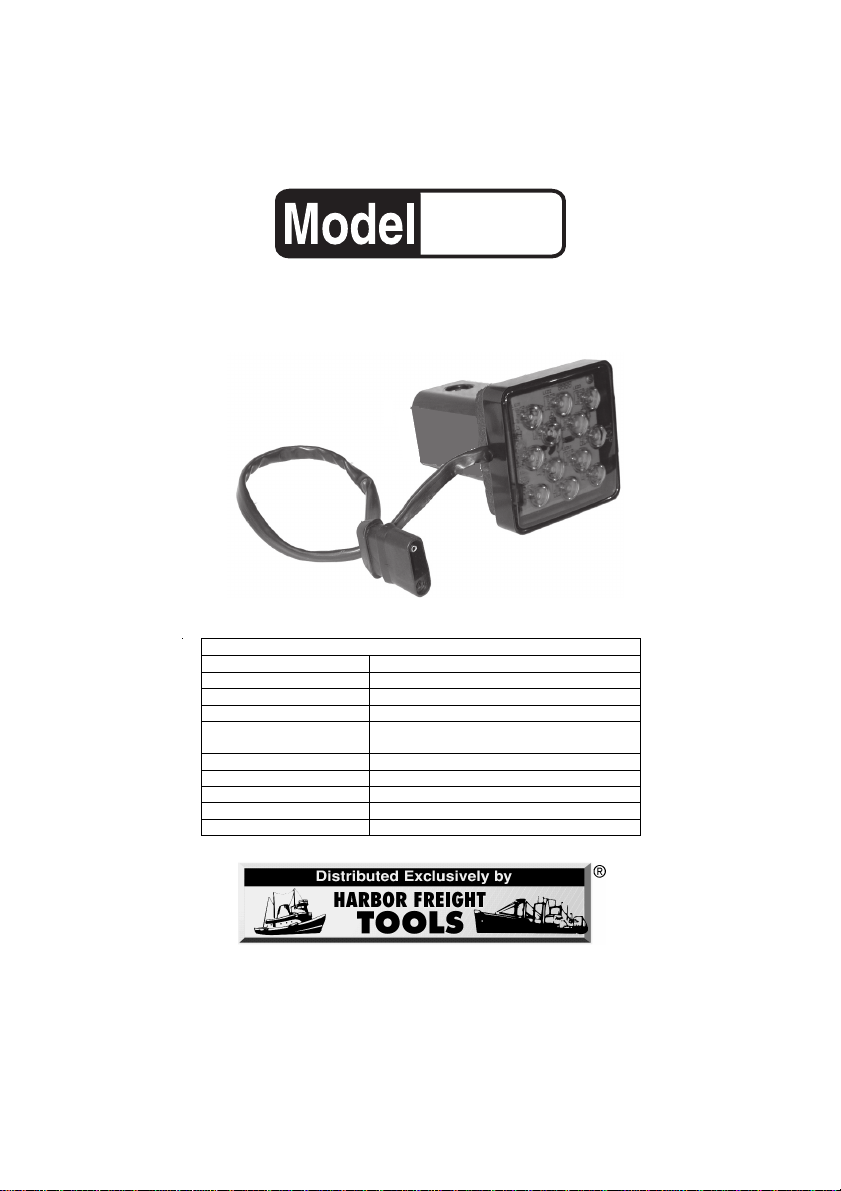
Lens Polystyrene, replaceable
Item Description
Light Source 12 bright red LED’s
Power Requirement 12 VDC
Power Wire 16 AWG x 2C x 13 (L ) inches; Flat four trailer
Hitch Pin Hole Diameter 5/8 inch
Dimensions 3-1/4 (square) x 4-3/8 (D) inches
Hitch Receiver Depth Two inches on square hitch
Weight 0.3 lbs.
Receiver Gasket 1/2 inch thick
3491 Mission Oaks Blvd., Camarillo, CA 93011
Visit our W eb site at http://www.harborfreight.com
Copyright © 2004 by Harbor Freight Tools®. All rights reserved. No por tion of this
manual or any artwork contained herein may be reproduced in any shape or form
without the express written consent of Harbor Freight Tools.
For technical questions and replacement parts, please call 1-800-444-3353
SPECIFICATIONS
plug (4-pin slip fit)
Page 2

Save This Manual
You will need the manual for the safety w arnings and precautions, assembly
instructions, operating and maintenance procedures, parts list and diagram. K eep
your invoice with this man ual. Write the invoice number on the inside of the front
cover. Keep the manual and in v oice in a safe and dry place for future reference.
Safety Warnings and Precautions
WARNING: When using this product, basic safety precautions should always
be followed to reduce the risk of personal injury and damage to equipment.
Read all instructions before using this tool!
1. Av oid w orking alone . If an accident happens, an assistant can bring help.
2. Observe work area conditions. Bef ore installing the Hitch Cover Brake
Light, always set the v ehicle emergency br ake and remo v e the ignition k e y
from the vehicle.
3. Keep children away. Children must never be allowed in the w ork area. Do
not let them handle machines, tools, or extension cords .
4. Check for damaged parts. Bef ore using this product, an y part that appears
damaged should be carefully checked to determine that it will operate
properly and perform its intended function. Chec k for alignment and binding
of moving parts; any broken parts or mounting fixtures; and an y other
condition that may affect proper oper ation. Any part that is damaged should
be properly repaired or replaced by a qualified technician.
5. Replacement parts and accessories. When servicing, use only identical
replacement parts. Use of any other parts will void the warranty. Only use
accessories intended for use with this tool. Appro v ed accessories are
available from Harbor Freight Tools.
6. Do not operate a vehicle or install this product if under the influence of
alcohol or drugs. Read warning labels if taking prescription medicine to
determine if your judgment or reflexes are impaired while taking drugs. If
there is any doubt, do not operate.
7. This product is intended to provide supplemental lighting and is not intended
to take the place of vehicle’s normal back lighting system.
Warning: The warnings, cautions, and instructions discussed in this instruction
manual cannot cover all possible conditions and situations that may occur. It
must be understood by the operator that common sense and caution are factors
which cannot be built into this product, but m ust be supplied by the operator .
SKU 92043 For technical questions, please call 1-800-444-3353 Page 2
Page 3

Unpacking
When unpacking, check to make sure that all parts are included. Ref er to the
Assembly Drawing and P arts List on the next page .
Installation
During installation, refer to the Assembly Drawing.
1. Set the vehicle emergency brake and remo v e the ignition k e ys.
2. Plug the vehicle’ s trailer br ak e light connector (Flat 4 trailer plug) into the
Hitch Cover Brak e Light Power Wire (A5) plug.
If the vehicle does not hav e an e xisting tr ailer brak e light cab le installed, hav e
one installed by a qualified technician. Note that the green wire on the Hitch
Cover Brak e Light is connected to the brak e light cab le of the v ehicle . The
other wire is connected to ground, or the chassis.
3. Remove the Cotter Pin (B2) from the Hitch Pin (B1). Slide the Hitch Pin from
the Hitch Cover Brak e Light.
4. With the Receiver Gasket in place against the Lens Housing (A4), slide the
Hitch Cover Brak e Light into the hitch receiv er .
5. Insert the Hitch Pin (B1) through the hole in the Hitch Cover Brake Light and
the hitch.
6. Secure the Hitch Pin (B1) by inserting the Cotter Pin (B2).
7. Test the Hitch Cover Brake Light b y pressing do wn on the vehicle brake
peddle. Ha v e another person view the Hitch Co v er Brak e Light.
8. Remove and store the Hitch Co ver Br ak e Light bef ore attempting to attach a
trailer to the vehicle hitch.
Maintenance
1. Pe riodically check that the Lens (A1) is securely seated in the Lens Housing
(A4).
2. Clean the Hitch Cover Brak e Light with a cloth dampened with w ater. Do not
spray the brak e light directly with a w ater hose.
3. When not in use, store the brake light in its original bo x to keep from
scratching the lens.
SKU 92043 For technical questions, please call 1-800-444-3353 Page 3
Page 4
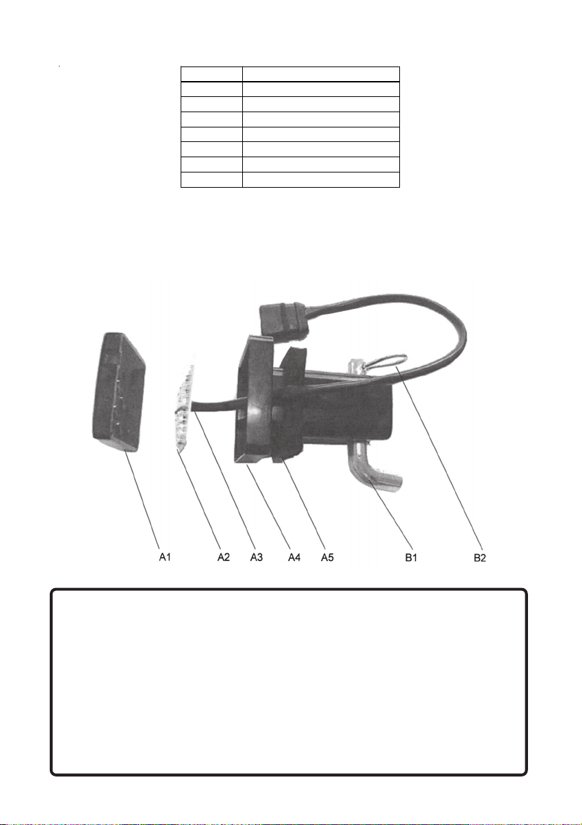
Parts List
Part No. Description
A1 Lens
A2 LED Lights (12V-2W)
A3 Power Wire with Plug
A4 Lens Housing
A5 Receiver Gaske t
B1 Hitch Pin
B2 Cotter Pin
NOTE: Some parts are listed and shown for illustration purposes only and are not
available individually as replacement parts.
Assembly Drawing
PLEASE READ THE FOLLOWING CAREFULLY
THE MANUFACTURER AND/OR DISTRIBUTOR HAS PROVIDED THE PARTS DIAGRAM
IN THIS MANUAL AS A REFERENCE TOOL ONLY. NEITHER THE MANUFACTURER NOR
DISTRIBUTOR MAKES ANY REPRESENTATION OR WARRANTY OF ANY KIND TO THE
BUYER THAT HE OR SHE IS QUALIFIED TO MAKE ANY REPAIRS TO THE PRODUCT OR
THAT HE OR SHE IS QUALIFIED TO REPLACE ANY PARTS OF THE PRODUCT. IN FACT,
THE MANUFACTURER AND/OR DISTRIBUTOR EXPRESSLY STATES THat ALL REPAIRS
AND P AR TS REPLACEMENTS SHOULD BE UNDER T AKEN BY CER TIFIED AND LICENSED
TECHNICIANS AND NOT BY THE BUYER. THE BUYER ASSUMES ALL RISK AND LIABILITY ARISING OUT OF HIS OR HER REP AIRS T O THE ORIGINAL PRODUCT OR REPLACEMENT P ARTS THERET O, OR ARISING OUT OF HIS OR HER INSTALLA TION OF REPLA CEMENT PARTS THERETO.
SKU 92043 For technical questions, please call 1-800-444-3353 Page 4
 Loading...