

Page 1
Page 2
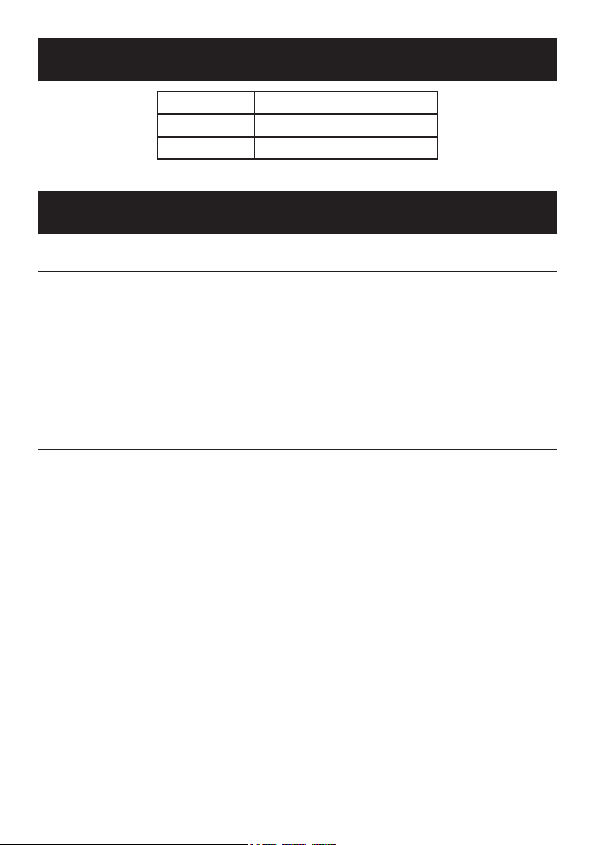
Specifications
Weight Capacity 2,000 lb.
Face Plate 9-3/4" W x 5-7/8" H x 13/16" thick
Wheel Diameter 3"
Important Safety Information
Assembly Precautions
1. Assemble only according to these
instructions. Improper assembly
can create hazards.
2. Wear ANSI-approved safety goggles
and heavy-duty work gloves
during assembly.
3. Keep assembly area clean and well lit.
4. Keep bystanders out of the
5. Do not assemble when tired
6. Weight capacity and other product
Use Precautions
Failure to heed these instructions may result in
personal injury and/or property damage:
1. Study, understand, and follow all
instructions before operating this device.
2. Do not exceed rated capacity.
Be aware of dynamic loading!
Sudden load movement may
briefly create excess load
causing product failure.
3. Use only on hard, level surfaces.
4. Lock mounting plate rotating
mechanism before applying a load.
5. Assure load is centered and secured
to mounting attachments.
6. Only use when Legs are fully
extended outward and Leg Lock
Pins and R-Pins are in place.
7. Hold Handle while removing the Pin.
8. Wear ANSI-approved safety goggles
9. Do not use for aircraft purposes.
10. Inspect before every use;
11. This product is not a toy. Do not allow
12. Use as intended only.
13. Maintain product labels and nameplates.
area during assembly.
or when under the influence
of drugs or medication.
capabilities apply to properly and
completely assembled product only.
and heavy-duty work gloves during use.
do not use if parts loose or damaged.
children to play with or near this item.
These carry important
safety information.
If unreadable or missing, contact
Harbor Freight Tools for a replacement.
Page 2 For technical questions, please call 1-800-444-3353. Item 69521
Page 3
Assembly Instructions
Read the ENTIRE IMPORTANT SAFETY INFORMATION section at the
beginning of this document including all text under subheadings therein
before set up or use of this product.
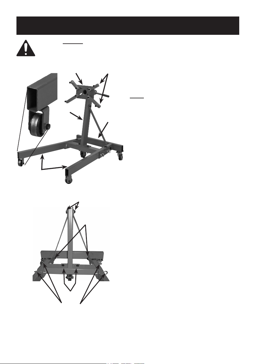
Left Leg
Wheel
Detail
Left & Right
Legs (1,9)
Figure A: Overall Assembly
Mounting
Plate (6)
Column (4)
Step 3
Step 4
Long & Short
Arms (8, 7)
Base (2)
1. Place the Right and Left Leg (1, 9)
pieces into the Base (2), lining up the
holes on the sides. Secure in place with
the Leg Lock Pins (15) and R-Pins (16).
Note: The wheel housing of the Right
and Left Legs (9, 1) are welded at an
angle from the Legs and are different from
each other. Be sure to insert the Legs into
the Base so that the wheels will be parallel,
pointing forward, not out to the sides.
2. Attach the Column (4) to the Base (2),
using the Bolts, Washers and Nuts (14).
Do not fully tighten the Bolts
in place until Step 4.
3. Align the holes of the Braces (3) on
either side of the Column (4) hole
and secure with the Bolts, Washers
and Nuts (13). Do not fully tighten
the Bolts in place until Step 4.
4. Align the bottom of the Braces (3)
with the holes on the inside of the
Base (2) frame and secure with
the Bolts, Washers and Nuts (17).
Tighten all Bolts from Steps 2 through 4.
Step 2
Step 1
Figure B: Steps 1 through 4
Page 3For technical questions, please call 1-800-444-3353.Item 69521
Page 4

Handle (5)
Bolt, Washer,
Nut (10)
Pin (12)
Column (4)
Short
Arm (7)
5. Slide the mounting post of
the Mounting Plate (6) into
the collar of the Column (4).
Align the holes and insert the Pin (12).
6. Slide off one of the Handle (5) rubber
grips, and insert the Handle (5)
through the large holes at the end
of the Mounting Plate (6) post.
Replace the rubber grip.
7. Attach the Arms (7,8) to the slots
in the Mounting Plate (6) using the
Bolts, Washers and Nuts (10).
Mounting
Plate (6)
Long Arm (8)
Figure C: Mounting Plate Installation
Page 4 For technical questions, please call 1-800-444-3353. Item 69521
Page 5
Operating Instructions
Read the ENTIRE IMPORTANT SAFETY INFORMATION section at the
beginning of this document including all text under subheadings therein
before set up or use of this product.
Mounting Engine
TO PREVENT SERIOUS INJURY:
Before attaching an engine to the stand, confirm that its weight
does not exceed the Stand maximum capacity.
1. Lock both Legs (1/9) in lowered position
with two Leg Lock Pins (15) per Leg
secured in place with R-pins (16).
2. Remove the Pin (12) from
the Column (4).
3. Determine the thread type and
length of bolts (not included) needed
to thread into the engine block.
Use grade 8 bolts that are long enough
to fit through the Arms and thread as
deeply as possible into the engine block.
4. Align the Short and Long Arms (7/8)
with four mounting bolt
locations on the engine.
WARNING! Use all four Arms when
attaching an engine to the Stand.
5. Place the bolts (not included) through
the Mounting Plate (6) side and securely
tighten them into the engine.
The bolt heads must press
against the back of the Arms:
if needed, use flat washers
(not included) as spacers.
6. Tighten the Bolts (10) and Nuts that
hold the Short and Long Arms (7/8)
to the Mounting Plate (6) securely.
7. Slowly lower the hoist/engine crane
(sold separately) until all the engine’s
weight is held by the stand.
8. Safely release the engine from
the hoist/engine crane.
9. Slowly rotate the engine to the
desired angle and insert the Pin (12)
into the top of the Column (4).
Rotating Engine
TO PREVENT SERIOUS INJURY: Be prepared for sudden engine
movement before removing Pin. Stay clear of engine.
1. While holding onto the Handle (5)
and the engine to prevent it from
accidental rotation, remove Pin (12).
Removing Engine
1. With assistance, rotate the
engine to its initial position.
2. Secure the engine properly to the crane.
Use the crane to support all of the
engine’s weight directly overhead,
but do not start lifting the engine stand.
2. Use assistance to rotate the engine
to the desired angle and insert the
Pin (12) into the top of the Column (4).
3. Once the engine is properly
supported by the crane,
remove the bolts securing the
Short and Long Arms (21) to the engine.
Page 5For technical questions, please call 1-800-444-3353.Item 69521
Page 6

Maintenance and Servicing
Procedures not specifically explained in this manual
must be performed only by a qualified technician.
TO PREVENT SERIOUS INJURY FROM STAND FAILURE:
Do not use damaged equipment. Make sure the stand is stable. If any unsafe
conditions are found, take it to a qualified technician for service or repair.
1. BEFORE EACH USE, inspect the
general condition of the Stand. Check
it for cracks, bends in the metal, signs
of unusual wear or any other condition
that may affect its safe operation.
If any are found, do not use the Stand.
2. Keep Engine Stand clean and
3. Before each use, check that
hardware is securely fastened.
4. Check that the Casters are
clean and turn properly.
5. AFTER USE, clean external surfaces
of the stand with a clean, moist cloth.
free of dirt or grease.
Folding the Stand for Storage
1
2
3
3
4
4. Insert the Leg Lock Pin (15) through
1. Remove the forward R-pin (16).
2. Remove the Leg Lock Pin (15).
3. Fold up the Leg (1/9).
the upper hole in the Base (2) so
that it holds the Leg in place, and
lock it in place with the R-pin.
5. Repeat for the other Leg.
WARNING! Do not use the Stand while it is folded. This is only for compact storage.
Record Serial Number Here:
Note: If product has no serial number,
record month and year of purchase instead.
Page 6 For technical questions, please call 1-800-444-3353. Item 69521
Note: Some parts are listed and shown
for illustration purposes only, and are not
available individually as replacement parts.
Page 7

Parts List and Diagram
Part Description Qty
1 Left Leg 1
2 Base 1
3 Brace 2
4 Column 1
5 Handle 1
6 Mounting Plate 1
7 Short Arm 2
8 Long Arm 2
9 Right Leg 1
Part Description Qty
10 Bolt Set M14 x 70 4
11 Big Washer 15 4
12 Pin 1
13 Bolt Set M14 x 70 1
14 Bolt Set M14 x 90 2
15 Leg Lock Pin 4
16 R-pin 4
17 Bolt Set M14 x 65 2
18 Nut M8 8
Part Description Qty
19 Spring Washer 8
20 Bolt M8*16 8
21 3" Swivel Caster 2
22 Bolt M12*65 3
23 Bushing 2
24 3" Wheel 2
25 Nut M12 3
26 Washer 12 3
27 2-1/2" Wheel 1
Page 7For technical questions, please call 1-800-444-3353.Item 69521
Page 8

PLEASE READ THE FOLLOWING CAREFULLY
THE MANUFACTURER AND/OR DISTRIBUTOR HAS PROVIDED THE PARTS LIST AND ASSEMBLY
DIAGRAM IN THIS DOCUMENT AS A REFERENCE TOOL ONLY. NEITHER THE MANUFACTURER
OR DISTRIBUTOR MAKES ANY REPRESENTATION OR WARRANTY OF ANY KIND TO THE
BUYER THAT HE OR SHE IS QUALIFIED TO MAKE ANY REPAIRS TO THE PRODUCT, OR
THAT HE OR SHE IS QUALIFIED TO REPLACE ANY PARTS OF THE PRODUCT. IN FACT, THE
MANUFACTURER AND/OR DISTRIBUTOR EXPRESSLY STATES THAT ALL REPAIRS AND PARTS
REPLACEMENTS SHOULD BE UNDERTAKEN BY CERTIFIED AND LICENSED TECHNICIANS,
AND NOT BY THE BUYER. THE BUYER ASSUMES ALL RISK AND LIABILITY ARISING OUT OF
HIS OR HER REPAIRS TO THE ORIGINAL PRODUCT OR REPLACEMENT PARTS THERETO,
OR ARISING OUT OF HIS OR HER INSTALLATION OF REPLACEMENT PARTS THERETO.
Limited 90 Day Warranty
Harbor Freight Tools Co. makes every effort to assure that its products meet high quality
and durability standards, and warrants to the original purchaser that this product is free from
defects in materials and workmanship for the period of 90 days from the date of purchase.
This warranty does not apply to damage due directly or indirectly, to misuse, abuse, negligence
or accidents, repairs or alterations outside our facilities, criminal activity, improper installation,
normal wear and tear, or to lack of maintenance. We shall in no event be liable for death,
injuries to persons or property, or for incidental, contingent, special or consequential damages
arising from the use of our product. Some states do not allow the exclusion or limitation of
incidental or consequential damages, so the above limitation of exclusion may not apply to you.
THIS WARRANTY IS EXPRESSLY IN LIEU OF ALL OTHER WARRANTIES, EXPRESS OR
IMPLIED, INCLUDING THE WARRANTIES OF MERCHANTABILITY AND FITNESS.
To take advantage of this warranty, the product or part must be returned to us with transportation
charges prepaid. Proof of purchase date and an explanation of the complaint must accompany
the merchandise. If our inspection verifies the defect, we will either repair or replace
the product at our election or we may elect to refund the purchase price if we cannot readily
and quickly provide you with a replacement. We will return repaired products at our expense,
but if we determine there is no defect, or that the defect resulted from causes not within
the scope of our warranty, then you must bear the cost of returning the product.
This warranty gives you specific legal rights and you may also
have other rights which vary from state to state.
3491 Mission Oaks Blvd. • PO Box 6009 • Camarillo, CA 93011 • (800) 444-3353
 Loading...