

Page 1

Page 2
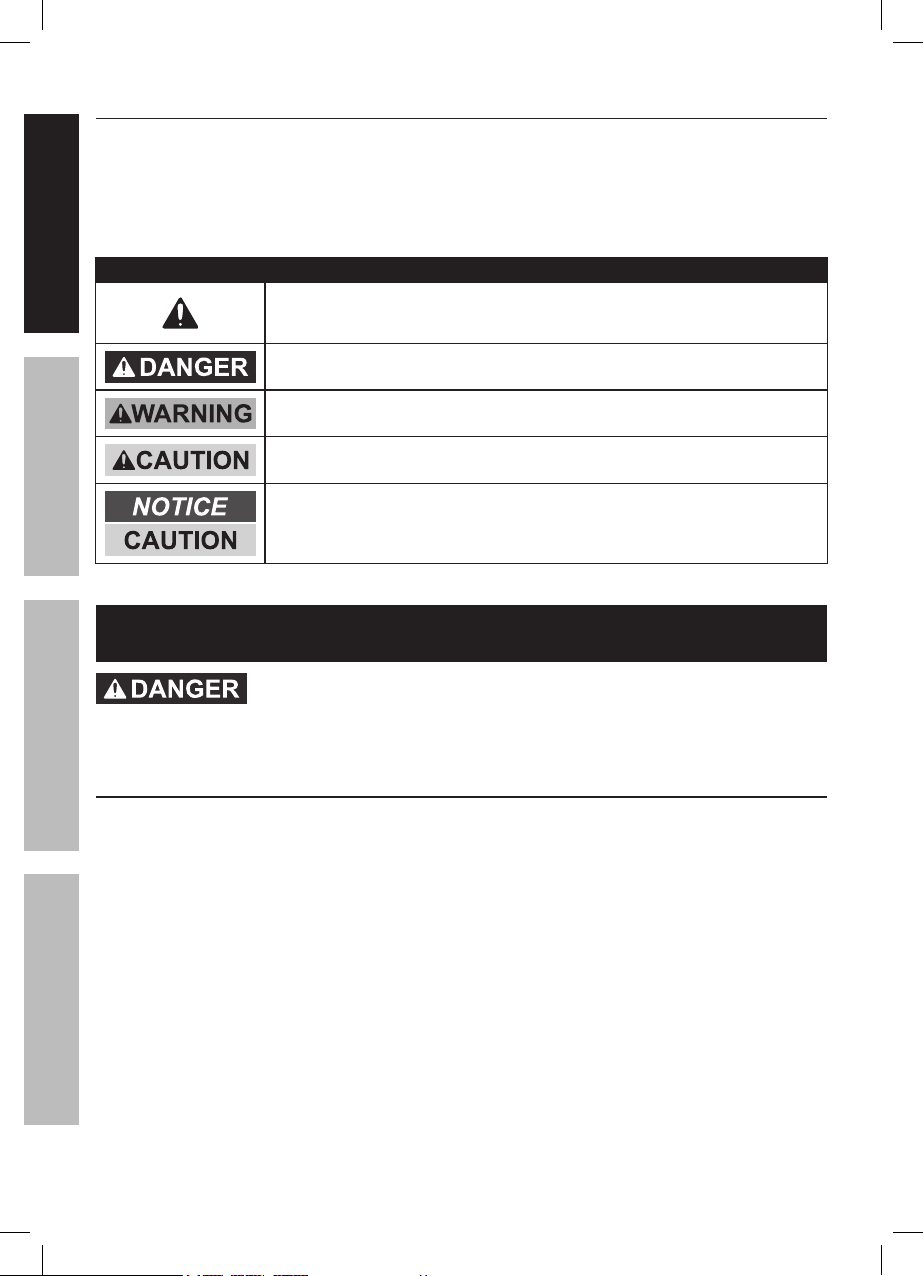
Table of Contents
Safety .................................................2
Specifications .....................................4
SAFETY OPERATION MAINTENANCEASSEMBLY
Assembly ............................................4
Operation ............................................8
WARNING SYMBOLS AND DEFINITIONS
This is the safety alert symbol. It is used to alert you to
potential personal injury hazards. Obey all safety messages
that follow this symbol to avoid possible injury or death.
Indicates a hazardous situation which, if not avoided,
Indicates a hazardous situation which, if not avoided,
Indicates a hazardous situation which, if not avoided,
could result in minor or moderate injury.
Addresses practices not related to personal injury.
Maintenance ......................................12
Parts List and Diagram ......................14
Warranty ............................................16
will result in death or serious injury.
could result in death or serious injury.
IMPORTANT SAFETY INFORMATION
TO PREVENT SERIOUS INJURY AND DEATH:
Basic Safety Information
1. Do not lift more than rated load.
Be aware of dynamic loading!
Sudden load movement may briefly create
excess load causing product failure.
2. Do not operate hoist when load
is not centered under hoist.
3. Do not operate hoist with twisted,
kinked, or damaged chain or rope.
4. Do not operate a damaged or
malfunctioning gantry crane.
Inspect gantry crane carefully and
test operation before every use.
5. Do not lift people or lift loads over people.
Falling loads can injure or kill people.
Page 2 For technical questions, please call 1-800-444-3353. Items 41188
69513
6. Do not operate with other
than manual power.
7. Do not remove or cover
warning labels and/or tags.
These carry important safety information.
If unreadable or missing, contact
Harbor Freight Tools for a replacement.
8. The warnings, precautions, and instructions
discussed in this instruction manual cannot
cover all possible conditions and situations
that may occur. It must be understood by
the operator that common sense and caution
are factors which cannot be built into this
product, but must be supplied by the operator.
Page 3

Assembly Specific Safety Information
1. Assemble completely according to instructions
and install Height Pins and R-pins before use.
Improper assembly can create hazards.
2. Assemble or adjust height
only with assistance.
3. Keep assembly area clean and well lit.
4. Keep bystanders out of the
area during assembly.
5. Do not assemble when tired or when under
the influence of drugs or medication.
6. Weight capacity and other product
capabilities apply to properly and
completely assembled product only.
7. Inspect the gantry crane as explained
in Frequent Inspection on page 12
after assembly but before use.
Operation Specific Safety Information
1. Use on a hard, smooth, level surface only.
The surface the gantry crane rests on must
be designed to withstand the loads and forces
imposed by the gantry crane for the rated load.
2. Use in location that allows the operator
to move and stay clear of the load.
3. Wear ANSI-approved safety goggles,
ANSI-approved hard hat, and steel-toed work
boots during setup and use.
4. This product is not a toy. Do not allow
children to play with or near this item.
5. Use as intended only.
Do not use to handle molten material.
Do not use for aircraft purposes.
6. Use crane at lowest height
possible for the application.
7. Do not adjust height while under load.
8. Do not move loaded crane.
SAFETYOPERATIONMAINTENANCE ASSEMBLY
Inspection, Testing, and Maintenance
Specific Safety Information
1. Perform a “Frequent Inspection”
at least monthly, see page 12.
2. Perform a “Periodic (Thorough) Inspection”
at least yearly, see page 12.
3. More frequent inspections are needed for
gantry cranes that are used heavily.
4. Raise test loads only to the minimum
extent needed and stay well clear of
load at all times during testing.
SAVE THESE INSTRUCTIONS.
69513
Page 3For technical questions, please call 1-800-444-3353.Items 41188
Page 4

Specifications
SAFETY OPERATION MAINTENANCEASSEMBLY
Load Rating 1 Ton (2,000 lb.)
Min. Height 99-1/2 IN. 100 IN.
Max. Height 148 IN. 147 IN.
Distance Between Posts 94 IN. 93 IN.
I-Beam 2-7/8 IN. W 3 IN. W
Model 41188 69513
Assembly
Read the ENTIRE IMPORTANT SAFETY INFORMATION section
at the beginning of this manual including all text under
subheadings therein before set up or use of this product.
TO PREVENT SERIOUS INJURY AND DEATH:
Wear ANSI-approved safety goggles, hard hat,
heavy-duty work gloves, and steel-toed work boots
during assembly and operation.
The correct bolts must be used during assembly. If any doubts arise regarding proper
assembly, contact Harbor Freight at the number at the bottom of this page before use.
Note: For additional information regarding the parts listed in the following pages,
refer to Parts List and Diagram on page 14.
Assembly Setup
1. Use a large, clean and uncluttered
area for assembly.
2. The Gantry Crane is large and heavy;
lay out parts on their sides and tighten and
erect entire assembly once complete.
3. More than one person will be
needed for assembly.
Page 4 For technical questions, please call 1-800-444-3353. Items 41188
69513
4. Use saw horses (not included) to
support larger items such as Posts
and I-Beam during assembly.
5. The Post Insert (1) and Post Sleeve (2)
are pre-assembled.
Page 5
Assembly Instructions
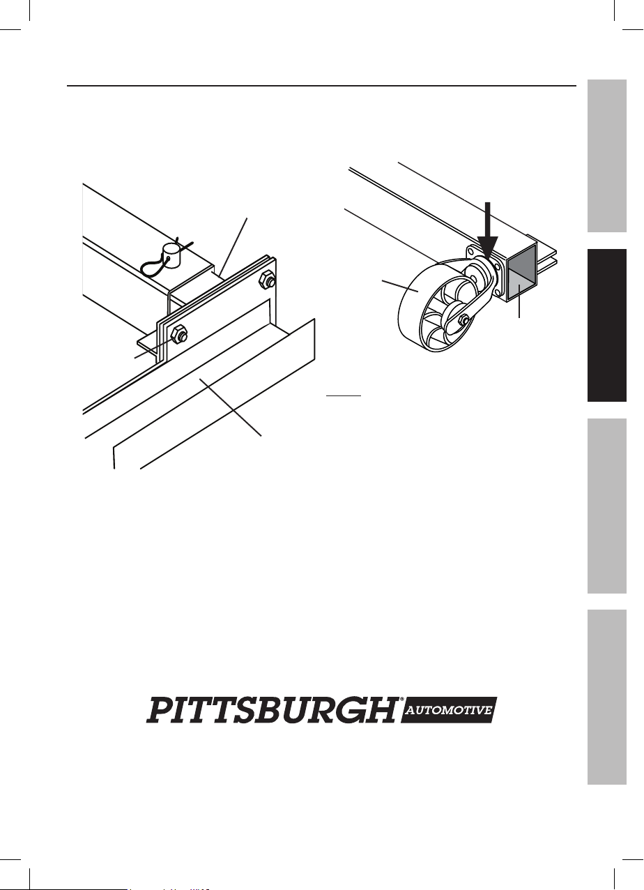
1. Attach each Post Insert (1) to the I-Beam (4)
using four Beam Bolts (29), Washers (19),
Spring Washers (15), and Nuts (16).
The Post Assemblies must be
turned so that the Pulley Boxes (6)
face outward. See Figure A.
Post Insert (1)
Bolt (29),
Washer (19)
I-Beam (4)
Figure A
2. Attach two Casters (9) to each
Base Assembly (3) using
Caster Bolts (11), Spring Washers (12),
and Nuts (13). See Figure B.
kingpin bearing
raceway
Caster
(9)
Base
Assembly (3)
Figure B
NOTE: Before attaching the Bases to the
Posts, apply grease to the kingpin bearing
raceway in each Caster. It is easier to grease
the Casters at this point as opposed to when
the Gantry Crane is complete. See Figure B.
SAFETYOPERATIONMAINTENANCE ASSEMBLY
69513
Page 5For technical questions, please call 1-800-444-3353.Items 41188
Page 6

3. Attach each Vertical Post Assembly to
each Base Assembly, making certain
that each Pulley Assembly (6) is to the
outside of the Crane. See Figure C.
SAFETY OPERATION MAINTENANCEASSEMBLY
Vertical Post (1, 2)
Base
Assembly (3)
Figure C
4. From the top, insert four Bolts (17)
through the base of the Vertical Post
Assembly and into Base Assembly.
Slip on Washer (19), Spring Washer (15)
and secure by tightening on Nuts (16).
5. Attach two Struts (5) to each Vertical
Post Assembly and Base Assembly.
Each Strut is attached to the one eyelet on
the side of the Vertical Post. See Figure D.
Strut (5)
Vertical
Post
(1, 2)
Base
Assembly (3)
Figure D
6. Insert a Frame Bolt (14) through the
top of the Strut. Slip on a Washer (19),
Spring Washer (15) and secure
with the Nut (16). Repeat for all four Struts.
7. Insert a Frame Bolt (14) through
the bottom of the Strut also.
Slip on a Washer (19), Spring Washer (15)
and secure with the Nut (16).
Repeat this also for all four Struts.
Page 6 For technical questions, please call 1-800-444-3353. Items 41188
69513
Page 7

8. Insert the Height Pin (7) through the
Vertical Post Assembly so that it goes all
the way through. Slide the R-Pin (18)
through the hole in the Height Pin to
secure the Inner Vertical Post into place.
Repeat for the second Vertical Post Assembly.
9. Tighten down all of the Nuts and Bolts and
make certain that the entire Telescoping
Gantry Crane Assembly is tight and secure.
10. With assistance, tilt the Gantry Crane
up and set it onto its base.
WARNING! More than one person is
needed for this procedure. See Figure E.
Figure E
11. Attach a Handle (8) to each Pulley (6).
See Figure F.
Pulley (6)
SAFETYOPERATIONMAINTENANCE ASSEMBLY
Handle (8)
Figure F
NOTE: Once Assembly is complete, tighten ALL Bolts before initial operation.
69513
Page 7For technical questions, please call 1-800-444-3353.Items 41188
Page 8

Operation
SAFETY OPERATION MAINTENANCEASSEMBLY
TO PREVENT SERIOUS INJURY and DEATH: The use of gantry cranes is subject
to certain hazards that cannot be met by mechanical means, but only by the
exercise of intelligence, care, common sense, and experience in anticipating
the motions that will occur as a result of operating the controls.
Wear ANSI-approved safety goggles, hard hat, heavy-duty work gloves,
and steel-toed work boots during operation.
Do not use without Locking Pins (7) in place and secured with R-Pins (18).
Do not exceed 1 Ton (2000 lb.) capacity.
NOTE: Once Assembly is complete, tighten ALL Bolts before initial operation.
The Gantry Crane can be used with a Push Trolley (ITEM 97392) and a hoist offered by Harbor Freight
Tools. Install trolley and hoist (both sold separately) according to manual instructions before operation.
Adjusting I-Beam Height
CAUTION! Use two people to
adjust the I-Beam height.
1. Remove the R-Pins (18) from the
Height Pins (7) and slide out Height Pins.
2. Once the Height Pins have been removed,
turn the Handles on both Pulley Assemblies
clockwise to raise the I-Beam.
Turn both counterclockwise to lower I-Beam.
CAUTION! To reduce the risk of tipping,
use crane at lowest height
possible for the application.
WARNING! Do not adjust the
legs to different heights.
3. Once the desired height has been reached,
reinsert the Height Pins and
secure in place with the R-Pins.
NOTE: The Vertical Post Assembly has nine
different stop positions. See Figure G.
3 of 9
Stop
Positions
Height
Pin (7)
R-Pin (18)
Figure G
Page 8 For technical questions, please call 1-800-444-3353. Items 41188
69513
Page 9

Before Operating Hoist
1. Familiarize yourself with all operating controls
of the hoist and with the operation(s) to be
performed. Instructions include, the warnings
on the hoist, and the safety and operating
instructions portion of this manual.
2. WARNING! TO PREVENT SERIOUS
INJURY FROM HOIST FAILURE:
Do not use damaged equipment.
If adjustments or repairs are necessary,
or any defects are known, have the
problem corrected before further use.
3. Do not operate a hoist with
an out-of-order sign.
4. Only a qualified technician should
perform maintenance to the hoist.
5. Designate a work area that
is clean and well-lit.
The work area must not allow
access by children or pets to
prevent distraction and injury.
6. There must not be objects, such as
utility lines, nearby that will present
a hazard while working.
7. Inspect the hoist as explained in
Frequent Inspection on page 12
after assembly but before use.
SAFETYOPERATIONMAINTENANCE ASSEMBLY
69513
Page 9For technical questions, please call 1-800-444-3353.Items 41188
Page 10

WARNING! Follow all safety warnings and instructions for the trolley and hoist you
will use with this gantry crane. Additional selected operation points follow:
SAFETY OPERATION MAINTENANCEASSEMBLY
Applying the Load
1. Attach the load to the load hook securely
by properly rated, suitable means,
such as chains, shackles, hooks,
lifting slings, etc. Load must be attached
to prevent accidental disconnection.
Figure H: — Correct and incorrect
load hook attachment
2. Properly seat the sling or other device
in the base (bowl or saddle) of the hook
(see the left side diagram on Figure H).
Do not allow the hook hitch to
support any part of the load.
3. Do not apply the load to the point of the hook
(shown in Figure H on the right side diagram).
4. Do not operate the hoist unless the
hoist unit is centered over the load.
5. Do not pick up a load in excess of the rated
load appearing on the hoist or load block,
except during properly authorized tests.
Do not use a hoist overload limiting device
to measure the maximum load to be lifted.
6. Give specific attention to load balancing and
hitching or slinging to prevent load slipping.
Page 10 For technical questions, please call 1-800-444-3353. Items 41188
69513
Page 11

Moving the Load
1. Do not engage in any activity which
will divert the operator’s attention
while operating the hoist.
2. Respond to signals from
a designated person only.
However, always obey a stop signal,
no matter who gives it.
3. Do not lift or lower a load with the hoist
until the operator and all other
personnel are clear of the load.
4. Make sure the load and hoist will clear all
obstacles before moving or rotating the load.
5. Do not lift a load more than a few inches until
it is well balanced in the sling or lifting device.
Parking the Load
1. Do not leave a suspended load
unattended unless specific precautions
have been instituted and are in place.
6. Each time a load approaching rated capacity
is handled, check hoist brake action by
lifting the load just clear of supports and
continuing only after verifying that the
brake system is operating properly.
7. WARNING! Do not carry any
load over any person.
8. WARNING! Do not carry personnel
on the hook or the load.
9. Avoid swinging the load or
load hook when traveling the hoist.
10. Avoid contact between trolleys and
between trolleys and stops.
11. Do not use the upper (or lower,
if provided) limit devices as a
normal means of stopping the hoist.
These are emergency devices only.
2. Position the load block above head level
for storage when the hoist is not in use.
3. Exercise care when removing a sling
from under a landed and blocked load.
SAFETYOPERATIONMAINTENANCE ASSEMBLY
69513
Page 11For technical questions, please call 1-800-444-3353.Items 41188
Page 12

Inspection, Testing, and Maintenance
SAFETY OPERATION MAINTENANCEASSEMBLY
TO PREVENT SERIOUS INJURY AND DEATH:
Before any inspection, testing or maintenance procedure:
Procedures not specifically explained in this manual
must be performed only by a qualified technician.
1. Move the gantry crane to a location where it will cause the least
interference with other cranes and operations in the area.
2. Land any load that is attached to the gantry crane.
3. Use warning signs and barriers on the floor beneath the gantry crane
where overhead maintenance work creates a hazard.
4. Wear ANSI-approved safety goggles, hard hat, heavy-duty work gloves,
and steel-toed work boots during operation.
Frequent Inspection
Perform the procedures in this
section BEFORE INITIAL USE and
AT LEAST MONTHLY. Inspection is needed
more often for heavily used cranes.
1. Check operating mechanisms for
proper operation, proper adjustment,
and unusual sounds.
2. Check upper limit device(s) of
attached cranes, if equipped, according
to manufacturer’s documentation.
3. Check hooks and hook latches (if used),
according to manufacturer’s documentation.
4. Check attached hoists, according to
manufacturer’s documentation.
Periodic (Thorough) Inspection
A qualified technician should perform
the procedures in this section
AT LEAST YEARLY. Inspection is needed
more often for heavily used cranes.
Remove or open access covers to
allow inspection of components.
1. First, follow all Frequent Inspection
procedures. Additionally:
2. Check for deformed, cracked,
or corroded members.
Page 12 For technical questions, please call 1-800-444-3353. Items 41188
69513
3. Check for loose or missing
bolts, nuts, pins, or rivets.
4. Check for other worn, cracked, or
distorted parts such as pins, bearings,
wheels, shafts, gears, rollers, locking and
clamping devices, bumpers, and stops.
5. Check attached hoists, according to
manufacturer’s documentation.
Page 13

Storage Inspection
1. A gantry crane that has been idle
for a period of a month or more,
but less than a year, must be inspected
before being placed in service according
to the Frequent Inspection requirements.
Maintenance
WARNING! TO PREVENT SERIOUS INJURY
FROM GANTRY CRANE FAILURE:
Do not use damaged equipment.
If any defect or damage is noted, have the
problem corrected before further use.
1. Repair or replacement of gantry crane
components must be performed
only by a qualified technician
using only identical replacement
parts with the same rating.
2. Some components may require adjustment.
The following are examples:
a. operating mechanisms
b. limit switches
c. control systems
d. brakes
2. A gantry crane that has been idle for a
period of a year or more, must be inspected
before being placed in service according
to the Periodic Inspection requirements,
and then tested according to the
procedure in the Testing section below.
3. Note the following regarding
specic components:
a. Replace damaged or worn hooks.
Do not repair them by welding or reshaping.
b. Replace or repair all critical parts
that are cracked, broken, bent,
excessively worn, or missing.
4. Do not repair load-sustaining members
by welding. Replace them as needed.
5. Lubrication:
a. Immobilize gantry crane before
lubrication by blocking casters.
b. Lubricate all moving parts regularly using
grease. Lubricate kingpin bearing raceway
on each caster, as shown in Figure B.
6. After maintenance work is completed and
before restoring the crane to normal operation:
a. reinstall guards;
b. reactivate safety devices;
c. remove replaced parts and loose material;
d. remove maintenance equipment.
SAFETYOPERATIONMAINTENANCE ASSEMBLY
Testing
1. Test repaired cranes and cranes
that have not been used for a year
or more, before being used.
2. First, with the crane unloaded,
check all functions of the crane, including:
a. lifting and lowering;
b. trolley travel;
c. bridge travel;
d. limit, locking and indicating
devices (if provided).
69513
3. After testing in the unloaded state,
attach up to a 2,000 Ib. total load
(including trolley and hoist weight,
do not exceed trolley or hoist capacity)
and carefully retest to check proper
load control and to check brake operation
along the full length of the bridge.
Page 13For technical questions, please call 1-800-444-3353.Items 41188
Page 14

Parts List and Diagram
SAFETY OPERATION MAINTENANCEASSEMBLY
PLEASE READ THE FOLLOWING CAREFULLY
THE MANUFACTURER AND/OR DISTRIBUTOR HAS PROVIDED THE PARTS LIST AND ASSEMBLY
DIAGRAM IN THIS MANUAL AS A REFERENCE TOOL ONLY. NEITHER THE MANUFACTURER
OR DISTRIBUTOR MAKES ANY REPRESENTATION OR WARRANTY OF ANY KIND TO THE
BUYER THAT HE OR SHE IS QUALIFIED TO MAKE ANY REPAIRS TO THE PRODUCT, OR
THAT HE OR SHE IS QUALIFIED TO REPLACE ANY PARTS OF THE PRODUCT. IN FACT, THE
MANUFACTURER AND/OR DISTRIBUTOR EXPRESSLY STATES THAT ALL REPAIRS AND PARTS
REPLACEMENTS SHOULD BE UNDERTAKEN BY CERTIFIED AND LICENSED TECHNICIANS,
AND NOT BY THE BUYER. THE BUYER ASSUMES ALL RISK AND LIABILITY ARISING OUT OF
HIS OR HER REPAIRS TO THE ORIGINAL PRODUCT OR REPLACEMENT PARTS THERETO,
OR ARISING OUT OF HIS OR HER INSTALLATION OF REPLACEMENT PARTS THERETO.
Parts List
Part Description Qty
Post Insert
1
Post Sleeve
2
Base
3
I-Beam
4
Strut
5
Pulley
6
Height Pin
7
Handle
8
Caster
9
Cable
10
Caster Bolt (M10 x 25)
11
Spring Washer
12
Nut (M10)
13
Frame Bolt (M12 x 50)
14
Spring Washer
15
Record Product’s Serial Number Here:
Note: If product has no serial number, record month and year of purchase instead.
Note: Some parts are listed and shown for illustration purposes only,
and are not available individually as replacement parts.
Page 14 For technical questions, please call 1-800-444-3353. Items 41188
69513
2
2
2
1
4
2
2
2
4
2
16
16
16
8
24
Part Description Qty
Nut (M12)
16
Post Bolt (M12)
17
R-Pin
18
Washer
19
Pulley
20
Pulley Bolt (M10 x 30)
21
Bracket
22
Inner Support
23
Support Bolt (M6)
24
Bracket Bolt (M8)
25
Spring Washer
26
Nut (M8)
27
Cable Clamp
28
Beam Bolt (M12 x 35)
29
24
8
2
24
2
2
2
4
8
2
2
2
4
8
Page 15

Assembly Diagram
SAFETYOPERATIONMAINTENANCE ASSEMBLY
28
29
29
69513
Page 15For technical questions, please call 1-800-444-3353.Items 41188
Page 16

Limited 90 Day Warranty
Harbor Freight Tools Co. makes every effort to assure that its products meet high quality
and durability standards, and warrants to the original purchaser that this product is free from
defects in materials and workmanship for the period of 90 days from the date of purchase. This
warranty does not apply to damage due directly or indirectly, to misuse, abuse, negligence or
accidents, repairs or alterations outside our facilities, criminal activity, improper installation,
normal wear and tear, or to lack of maintenance. We shall in no event be liable for death,
injuries to persons or property, or for incidental, contingent, special or consequential damages
arising from the use of our product. Some states do not allow the exclusion or limitation of
incidental or consequential damages, so the above limitation of exclusion may not apply to
you. THIS WARRANTY IS EXPRESSLY IN LIEU OF ALL OTHER WARRANTIES, EXPRESS
OR IMPLIED, INCLUDING THE WARRANTIES OF MERCHANTABILITY AND FITNESS.
To take advantage of this warranty, the product or part must be returned to us with
transportation charges prepaid. Proof of purchase date and an explanation of the complaint
must accompany the merchandise. If our inspection verifies the defect, we will either repair or
replace the product at our election or we may elect to refund the purchase price if we cannot
readily and quickly provide you with a replacement. We will return repaired products at our
expense, but if we determine there is no defect, or that the defect resulted from causes not
within the scope of our warranty, then you must bear the cost of returning the product.
This warranty gives you specific legal rights and you may also
have other rights which vary from state to state.
3491 Mission Oaks Blvd. • PO Box 6009 • Camarillo, CA 93011 • (800) 444-3353
 Loading...