

Page 1
Stud/Voltage Detector
When unpacking, make sure that the
product is intact and undamaged.
If any parts are missing or broken,
please call 1‑800‑444‑3353
as soon as possible.
Item 67801
INSTRUCTIONS AND
PRECAUTIONS
Visit our website at:
http://www.harborfreight.com
Read this material before using
this product. Failure to do so
can result in serious injury.
SAVE THIS MANUAL.
Copyright© 2011 by Harbor Freight Tools®.
All rights reserved. No portion of this document
or any artwork contained herein may be
reproduced in any shape or form without the
express written consent of Harbor Freight Tools.
Diagrams within this document may not be
drawn proportionally. Due to continuing
improvements, actual product may differ slightly
from the product described herein. Tools required
for assembly and service may not be included.
For technical questions,
please call 1‑800‑444‑3353.
Specications
Battery 1x 9V
Stud Range <3/4″ Deep
Ferrous Metal Range <1-1/2″ Deep
Copper Pipe Range <1-3/16″ Deep
Voltage Range
90‑250 V~, 50‑60 Hz
(unshielded)
<1-1/2″ Deep
Important Safety Information
1. This device may not detect items
that are shielded, behind dense
materials (such as plywood),
or are deeper than its listed
detection depths.
2. This product is not a toy.
Do not allow children to play
with or near this item.
3. Inspect before every use; do not
use if parts are loose or damaged.
4. Maintain product labels and
nameplates. These carry important
safety information. If unreadable
or missing, contact Harbor Freight
Tools for a replacement.
5. Position batteries in proper polarity
and do not install batteries of
different types, charge levels,
or capacities together.
Page 2
Instructions
Read the ENTIRE
IMPORTANT SAFETY
INFORMATION section
at the beginning of this
document before set up
or use of this product.
4. The Power LED shows that the unit
is on and ready to start detecting.
5. The Low Battery LED lights
when the battery voltage is low.
Low battery voltage may effect
performance. DO NOT USE IF
BATTERY VOLTAGE IS LOW.
Stud Detection
3
4
2
1
5
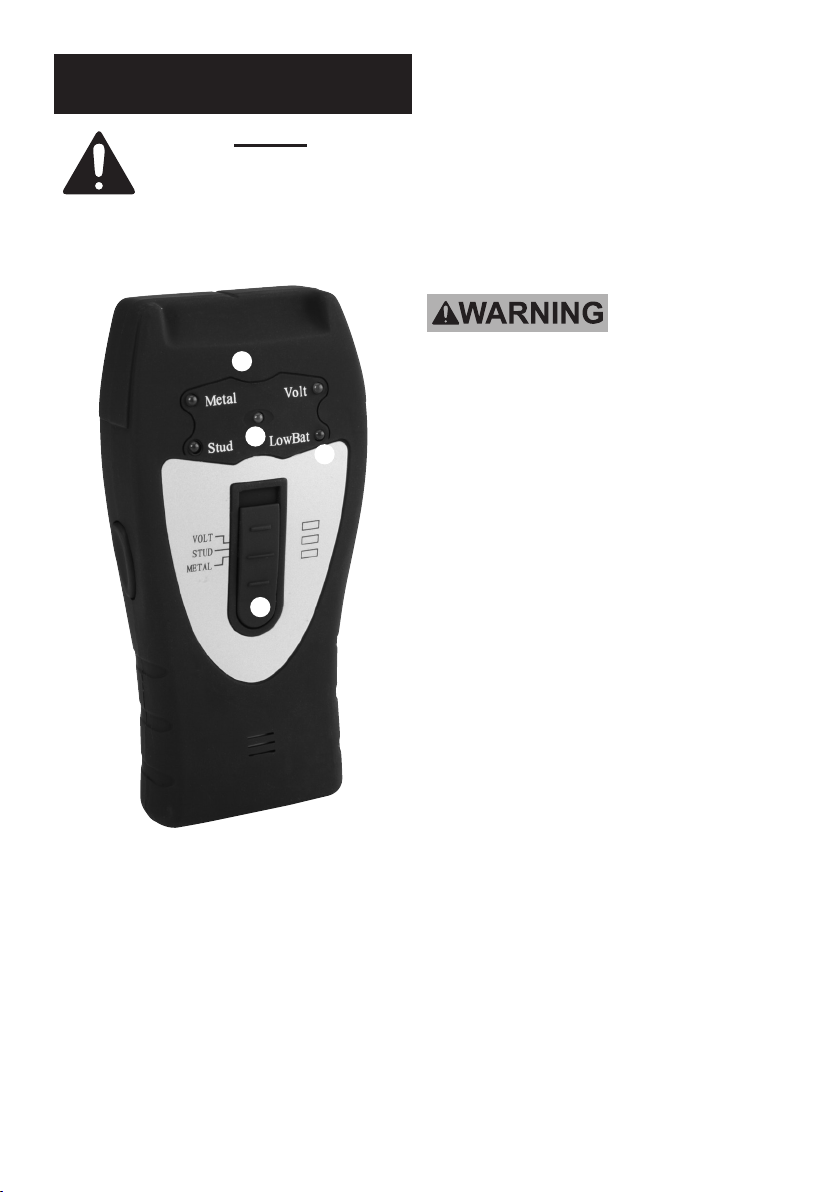
Figure A: Controls
1. Use the Mode Switch to
select what type of material
you want to detect.
2. The Power Button activates
the detector while pressed.
Release it to turn the detector off.
3. The Indicator LED’s show what
type of material is detected:
Metal, Voltage or Stud.
TO PREVENT SERIOUS INJURY AND
ELECTROCUTION:
Turn off all circuits with wires
inside the wall before working.
Depending on the proximity of
electrical wiring or pipes to the wall
surface, the scanner may detect
them in the same manner as studs.
Use caution when nailing, cutting, or
drilling in walls, oors, and ceilings
that may contain these items.
Studs or joists are normally spaced
16″ or 24″ apart and are 1-1/2″ wide.
Anything closer together or of
a different width may not be
a stud, joist, or rebreak.
1. Slide the Switch to the
“STUD” position.
2. Hold the detector at against the
wall. Press and hold Power Button.
3. The Power LED lights when the
detector is ready to operate.
4. Slowly slide unit horizontally
across wall, left to right. Keep the
unit base in contact with the wall.
The Stud LED lights and the unit
starts emitting a steady tone when
it detects the edge of a stud.
When that happens, mark the spot
over the top center of the detector.
Page 2 For technical questions, please call 1‑800‑444‑3353. SKU 67801
Page 3

5. Place the unit on the wall a few
inches to the right of where it
detected the stud. Then move it
slowly from right to left, horizontally
across the wall and mark the spot
when stud detects again. Between
the two spots is the stud position.
6. Repeat the process to
conrm position of studs.
Metal Detection
1. Slide the switch to the
“METAL” position.
2. Press and hold Power Button.
Calibrate the unit in air away
from metal objects.
3. The Power LED lights when the
detector is ready to operate.
Position unit at against wall.
4. Slowly slide unit horizontally
across wall, left to right. Keep the
unit base in contact with the wall.
The Metal LED lights and the unit
starts emitting a steady tone when it
detects the edge of a metal object.
When that happens, mark the spot
over the top center of the detector.
5. Place the unit on the wall a few
inches to the right of where
it detected the metal object.
Then move it slowly from right to
left, horizontally across the wall
and mark the spot when Metal
detects again. Between the two
spots is the metal object’s position.
6. Repeat the process to conrm
position of metal objects.
Voltage Detection
TO PREVENT SERIOUS INJURY AND
ELECTROCUTION:
The unit will not detect live wires
inside metal pipe or metal conduit,
behind metallic wall covering, or
behind some plywood or other dense
materials. Use extra caution in these
construction situations. Always turn
the power off when nailing, cutting,
or drilling near electrical wire.
NOTE: Because the unit is sensitive
it may indicate metal while passing
through the air. Simply release
Power Button, place on the wall, and
press Power Button on again. This
effectively re‑calibrates the electronics.
The unit detects from 90 to 250 V at
50 to 60 Hz AC in a HOT unshielded
electrical wire that is within 1‑1/2″ of
wall surface. The sensor is located
in the center of the back of the unit.
1. Turn power on in the wall you
will try to detect voltage in.
The power must be turned off later
after detection and before work to
reduce the risk of accidental shock.
2. Slide the switch to the
“VOLT” position.
3. Press and hold Power Button.
Calibrate the unit in air away
from metal objects.
4. The Power LED lights when the
detector is ready to operate.
Position unit at against wall.
5. Slowly slide unit horizontally
across wall, left to right. Keep the
unit base in contact with the wall.
The Volt LED lights and the unit
Page 3For technical questions, please call 1‑800‑444‑3353.SKU 67801
Page 4

starts emitting a steady tone when
it detects the edge of a live wire.
When that happens, mark the spot
over the top center of the detector.
6. Place the unit on the wall
a few inches to the right of
where it detected the live wire.
Then move it slowly from right
to left, horizontally across the
wall and mark the spot when Volt
detects again. Between the two
spots is the live wire’s position.
7. Repeat the process to conrm
position of live wires.
8. WARNING! TO PREVENT
SERIOUS INJURY AND DEATH
FROM ACCIDENTAL SHOCK:
Turn off all circuits within
the wall after detection and
before working on the wall.
Battery Replacement
Before rst use or if Low Battery LED
lights up, then replace the batteries:
1. Open battery door on back of case.
2. Connect a 9‑volt battery
to battery clip.
3. Insert battery into case and
replace battery door.
Record Serial Number Here:
Note: If product has no serial
number, record month and
year of purchase instead.
Note: Replacement parts are
not available for this item.
Page 4 For technical questions, please call 1‑800‑444‑3353. SKU 67801
 Loading...